EP1907678B1 - Multipurpose engine - Google Patents
Multipurpose engine Download PDFInfo
- Publication number
- EP1907678B1 EP1907678B1 EP06767207.1A EP06767207A EP1907678B1 EP 1907678 B1 EP1907678 B1 EP 1907678B1 EP 06767207 A EP06767207 A EP 06767207A EP 1907678 B1 EP1907678 B1 EP 1907678B1
- Authority
- EP
- European Patent Office
- Prior art keywords
- engine
- main body
- cover
- multipurpose
- electrical
- Prior art date
- Legal status (The legal status is an assumption and is not a legal conclusion. Google has not performed a legal analysis and makes no representation as to the accuracy of the status listed.)
- Not-in-force
Links
- 238000009429 electrical wiring Methods 0.000 claims description 37
- 239000007858 starting material Substances 0.000 claims description 20
- 238000001816 cooling Methods 0.000 claims description 10
- 239000002828 fuel tank Substances 0.000 claims description 9
- 238000010586 diagram Methods 0.000 description 6
- 239000000446 fuel Substances 0.000 description 6
- 238000005192 partition Methods 0.000 description 5
- 238000001514 detection method Methods 0.000 description 4
- 238000012423 maintenance Methods 0.000 description 4
- 239000011347 resin Substances 0.000 description 3
- 229920005989 resin Polymers 0.000 description 3
- 238000002485 combustion reaction Methods 0.000 description 2
- 230000008439 repair process Effects 0.000 description 2
- 238000007599 discharging Methods 0.000 description 1
- 230000000694 effects Effects 0.000 description 1
- 239000003502 gasoline Substances 0.000 description 1
- 239000000314 lubricant Substances 0.000 description 1
- 239000000463 material Substances 0.000 description 1
- 238000000638 solvent extraction Methods 0.000 description 1
- 230000008016 vaporization Effects 0.000 description 1
Images






Classifications
-
- F—MECHANICAL ENGINEERING; LIGHTING; HEATING; WEAPONS; BLASTING
- F02—COMBUSTION ENGINES; HOT-GAS OR COMBUSTION-PRODUCT ENGINE PLANTS
- F02B—INTERNAL-COMBUSTION PISTON ENGINES; COMBUSTION ENGINES IN GENERAL
- F02B77/00—Component parts, details or accessories, not otherwise provided for
-
- F—MECHANICAL ENGINEERING; LIGHTING; HEATING; WEAPONS; BLASTING
- F02—COMBUSTION ENGINES; HOT-GAS OR COMBUSTION-PRODUCT ENGINE PLANTS
- F02B—INTERNAL-COMBUSTION PISTON ENGINES; COMBUSTION ENGINES IN GENERAL
- F02B63/00—Adaptations of engines for driving pumps, hand-held tools or electric generators; Portable combinations of engines with engine-driven devices
- F02B63/04—Adaptations of engines for driving pumps, hand-held tools or electric generators; Portable combinations of engines with engine-driven devices for electric generators
-
- F—MECHANICAL ENGINEERING; LIGHTING; HEATING; WEAPONS; BLASTING
- F02—COMBUSTION ENGINES; HOT-GAS OR COMBUSTION-PRODUCT ENGINE PLANTS
- F02B—INTERNAL-COMBUSTION PISTON ENGINES; COMBUSTION ENGINES IN GENERAL
- F02B63/00—Adaptations of engines for driving pumps, hand-held tools or electric generators; Portable combinations of engines with engine-driven devices
-
- F—MECHANICAL ENGINEERING; LIGHTING; HEATING; WEAPONS; BLASTING
- F02—COMBUSTION ENGINES; HOT-GAS OR COMBUSTION-PRODUCT ENGINE PLANTS
- F02B—INTERNAL-COMBUSTION PISTON ENGINES; COMBUSTION ENGINES IN GENERAL
- F02B63/00—Adaptations of engines for driving pumps, hand-held tools or electric generators; Portable combinations of engines with engine-driven devices
- F02B63/04—Adaptations of engines for driving pumps, hand-held tools or electric generators; Portable combinations of engines with engine-driven devices for electric generators
- F02B63/042—Rotating electric generators
Definitions
- the present invention relates to a multipurpose engine according to the preamble of claim 1.
- a starter 312, a rectifier 313, a magnet switch 314, a startup switch 315, and other electrical components are disposed on the lateral surface of the engine 311. These electrical components are connected to each other by electrical wiring 316.
- the electrical wiring 316 is laid out without being fixed to the lateral surface of the engine 311, and the electrical wiring is subjected to vibration from the operation of the engine 311.
- a multipurpose engine is therefore desired that eliminates the effects of vibration on the electrical wiring, and that has an electrical wiring structure in which the electrical components are easy to maintain, and which is inexpensive
- a multipurpose engine characterized in comprising an engine main body; a generator operated by the driving force of the engine; auxiliary components comprising a fuel tank, an air cleaner, a muffler, and other components disposed on the engine main body; an electrical component comprising a starter, a main switch, and the like; and a plurality of electrical wirings for connecting the generator and the electrical component to each other; wherein each of the plurality of electrical wirings is connected inside a connector box provided to the side of the engine main body and disposed in a gap formed between the engine main body and the auxiliary components.
- the electrical wirings are thus interconnected inside the connector box in the engine of the present invention, the connections between electrical components can be concentrated within the connection box. As a result, the electrical components can be made easier to maintain, and repairs can be performed rapidly.
- the multipurpose engine of the present invention is furthermore provided with a cooling fan provided coaxially with the output shaft of the engine main body, and a fan cover provided to the engine main body so as to cover the cooling fan, wherein the fan cover is integrally formed with the connector box.
- the connector box is preferably provided in a position that is adjacent to an operating panel on which the main switch is mounted.
- the condition of the electrical wiring can therefore be checked while the functionality of the main switch and other operating members is confirmed. This results in improved convenience during maintenance.
- Retainers for retaining the plurality of electrical wirings are preferably provided to the connector box. Vibration of the electrical wiring is therefore easily prevented. This makes the connections between electrical components more reliable.
- the multipurpose engine 10 shown in FIGS. 1 through 3 includes an engine main body 27 and auxiliary components that are composed of accessories for operating the engine main body 27.
- the auxiliary components primarily include an air cleaner 35 for drawing in outside air, a carburetor 36 for vaporizing fuel (gasoline) and feeding the fuel to a combustion chamber 29, a fuel tank 37 for storing the fuel, a muffler 40 for reducing the exhaust noise from the exhaust gas, a recoil starter 39 for starting the engine main body 27, an oil level detection device (oil alarm) 50 for detecting the oil level, a plug cap 60 that houses an ignition unit 204 (see FIG. 10 ) for performing ignition, and other components.
- the engine main body 27 shown in the drawings is an overhead-camshaft (OHC) air-cooled engine in which the cylinder is tilted.
- the engine main body 27 is provided with a crankcase 13 for storing oil (lubricant) 12, a crankshaft 14 that is rotatably mounted parallel to the crankcase 13, a single-cylinder block 15 integrally formed with the crankcase 13 at an angle, a piston 17 that is slidably mounted to the cylinder 16 of the cylinder block 15, a connecting rod 18 for connecting the piston 17 and the crankshaft 14, a cylinder head 21 mounted to the open portion 19 of the cylinder block 15, an intake valve 24 provided to the intake port 22 of the cylinder head 21, and an exhaust valve 25 provided to the exhaust port 23 of the cylinder head 21.
- the casing 28 is composed of the crankcase 13, the cylinder block 15, and the cylinder head 21.
- the combustion chamber 29 is composed of the cylinder block 15 and the cylinder head 21.
- the crankshaft 14 has a power takeoff unit 31 at one end thereof.
- This power takeoff unit 31 is referred to as a power take-off (PTO).
- the cylinder head 21 is provided with a valve movement chamber 32 for driving the intake valve 24 and the exhaust valve 25 through the rotation of the crankshaft 14.
- Reference numeral 33 in the drawings indicates the oil level gauge.
- An exhaust pipe 45 for discharging the exhaust gas is mounted to the muffler cover 41.
- the oil is supplied from an oil supply vent 42.
- One end of the exhaust duct 43 extends from the cylinder head 21.
- the muffler 40 is mounted to the other end of the exhaust duct 43.
- the recoil starter 39 has a starting knob (grip) 44.
- the generator 46 and the cooling fan 47 are mounted on opposite sides of the power take-off 31 (see FIG. 1 ) of the crankshaft 14.
- the recoil starter 39 is covered by a recoil starter cover 49.
- a connecting duct (intake duct) 38 is connected to the air cleaner 35.
- the generator 46 is composed of a starter 71 that is mounted to the cylinder block 15 on the side of the other end of the crankshaft 14, and a rotor 72 that is mounted to the crankshaft 14 around the starter 71 and has a pulse coil (rotation detection sensor) 77 for detecting the number of revolutions of the generator 46.
- the cooling fan 47 is provided coaxially with the crankshaft (output shaft) 14, is mounted outside the rotor 72, and is covered by a fan cover 48 provided to the cylinder block 15.
- the recoil starter 39 starts the engine main body 27.
- the starter is composed of a recoil starter cover 49 that is supported on the side of the cylinder block 15, a pulley 74 that is rotatably mounted to this recoil starter cover 49, a return spring (not shown in the drawing) that returns the pulley 74 to the initial state and is provided between the pulley 74 and the recoil starter cover 49, a latch 75 for meshing with a cup 73 during rotation of the pulley 74, a rope 76 wrapped on the pulley 74, and a starting knob 44 (see FIG. 3 ) mounted to the distal end of this rope 76.
- the cup 73 is mounted on the outside of the cooling fan 47.
- the fuel tank 37, the air cleaner 35, the muffler 40 ( FIG. 1 ), and other auxiliary components are disposed above the cylinder block 15.
- An electrical wiring bundle 103 that is routed to the generator 46 (see FIG. 4 ) or to the main switch 101 or another electrical component is provided around the cylinder block 15.
- the operating panel 51 is composed of a main panel 52 and a cover panel 53.
- the main switch 101, volume 102, and other electrical components are arranged in the elongated main panel 52 formed from a resin.
- the main panel 52 is disposed on the upper side of the recoil starter cover 49.
- a cover panel 53 formed from a resin covers the electrical wiring bundle 103.
- the cover panel 53 is connected to the main panel 52 and is provided between the fuel tank 37 and the recoil starter cover 49.
- the main switch 101 is an electrical component for switching on the engine main body 27, and has a switch knob 54 for switching on the engine main body 27.
- the volume 102 is an electrical component for adjusting the characteristics of the governor motor 203 ( FIG. 10 ) of the carburetor 36 ( FIG. 2 ).
- the volume has an adjustment knob 55.
- the switch knob 54 and the adjustment knob 55 together constitute an operating member.
- a fan cover 48 composed of a resin material is mounted on the engine main body 27 ( FIG. 1 ) to cover and protect the cooling fan 47 ( FIG. 5 ).
- the fan cover 48 is composed of a partition wall 106 for partitioning the cooling fan 47 ( FIG. 5 ) from the recoil starter 39 ( FIG. 5 ), an opening 107 formed in the partition 106 in order to discharge hot air to the outside via the cooling fan 47, a connector box 104 that houses the electrical wiring bundle 103 ( FIG. 5 ) and is provided to the top of the partition wall 106, and a housing 108 that is positioned beside the connector box 104 and encloses the main switch 101 ( FIG. 5 ), the volume 102, and other electrical components.
- the partition wall 106 is provided with a fastener 111 for fastening the partition wall 106 to the cylinder block 15 ( FIG. 5 ), and a fixing boss 112 for securing the recoil starter cover 49 ( FIG. 5 ).
- the connector box 104 is provided with a first connector housing 113, and a second connector housing 114 that is separated from the first connector housing 113 by a substantially U-shaped open portion 115.
- the box forms a housing for the electrical wiring.
- the electrical wiring bundle 103 can be connected inside the connector box 104.
- the connector box 104 is detachable from the cover panel 53 ( FIG. 5 ).
- the connector box 104 is provided in integral fashion to the fan cover 48, the cost of the structure can be reduced.
- the first connector housing 113 is designed so as to be capable of enclosing harnesses 151, 152, 153, 154, 155, and 156.
- the first connector housing 113 is a part that allows for connection or disconnection of these harnesses 151 through 156.
- the first harness 151 extends from the side of the carburetor 36 ( FIG. 2 ).
- the second harness 152 is branched from the first harness 151.
- the volume-side harness 154 is connected to the second harness 152.
- the third harness 153 extends from the ignition unit (ignition coil) 204 ( FIG. 10 ) housed in the plug cap 60 ( FIG. 2 ).
- the main-switch-side harness 155 is connected to the third harness 153.
- the relay harness 156 is relayed to the first harness 151.
- the first through third harnesses 151 through 153, the volume-side harness 154, the main-switch-side harness 155, and the relay harness 156 constitute electrical wiring.
- the first through third harnesses 151 through 153 have plugs 161 through 163, respectively, at the distal ends thereof.
- the volume-side harness 154 has a socket 164 at the distal end thereof.
- the main-switch-side harness 155 has a socket 165 at the distal end thereof.
- the relay harness 156 has a socket 166.
- the first connector housing 113 has a first retainer 171 for retaining the plug 161 of the first harness 151 ( FIG. 7A ), a volume-side retainer 174 for retaining the socket 164 of the volume-side harness 154, a switch-side retainer 175 for retaining the socket 165 of the main-switch-side harness 155, a hole 176 through which the relay harness 156 is inserted, engaging units (engaging tabs) 177 and 177 for locking the cover panel 53 ( FIG. 5 ), and locking bosses 178 and 178 for fastening the cover panel 53.
- the first harness 151 has a plug 181 at the other end thereof.
- a separate harness 182 extends from the plug 181.
- the third harness 153 passes through the open portion 115 and the second connector housing 114.
- the second connector housing 114 has retainer 183 that is shaped as an L in cross section and that supports the third harness 153, and an I-type retainer 184 for supporting the third harness 153.
- the second connector housing 114 has a notch 185 that opens toward the open portion 115, for retaining the separate harness 182 ( FIG. 8A ).
- the cover panel 53 is composed of a first cover unit 191 that is covered by the first connector housing 113 ( FIG. 6 ), an open cover unit 193 for covering the open unit 115 ( FIG. 8B ), and a second cover unit 192 for covering the second connector housing 114, and these cover units are integrally formed.
- the first cover unit 191 has engaging holes 194 and 194 into which the engaging tabs 177 and 177 ( FIG. 7B ) are locked, and a locking unit 195 that corresponds to one of the locking bosses 178 ( FIG. 7B ).
- the open cover unit 193 has a locking unit 196 that corresponds to the other locking boss 178.
- the second cover unit 192 has an expanded portion 197 that is expanded to the outside from the engine main body 27 ( FIG. 1 ) and that covers the plug 181 mounted to the other end of the first harness 151 ( FIG. 8A ).
- the electrical power generated by the generator 46 is fed to an Electronic Controlled Unit (ECU) 201.
- ECU Electronic Controlled Unit
- the following types of information are received in the ECU 201: the oil level information outputted from the oil level detection device (oil alarm) 50, the information from the pulse coil (rotation detection sensor) 77 for detecting the revolutions of the generator 46, and the information from a temperature sensor 202 for detecting the temperature of the cylinder block 15 ( FIG. 1 ).
- the state of the main switch 101 is determined and the information from the volume 102 for adjusting the characteristics of the governor motor 203 provided to the carburetor 36 ( FIG. 2 ) is received.
- the ECU 201 sends ignition information to the ignition coil 204 provided to the plug cap 60 ( FIG. 2 ), sends throttle opening information to the governor motor 203, and sends drive information to a fuel cutoff solenoid 205 for stopping the supply of fuel.
- the ECU 201 also includes a diagnostic unit 206 for diagnosing failures.
- the diagnostic results from this diagnostic unit 206 are displayed by a Light Emitting Diode (LED) 207.
- LED Light Emitting Diode
- the generator 46, ECU 201, oil alarm 50, pulse coil 77, ignition coil 204, and fuel cutoff solenoid 205 are all electrical components.
- the design properties of the multipurpose engine 10 can be enhanced by covering the harnesses (electrical wiring) 151 through 156 ( FIG. 11B ) as shown in FIG. 11A .
- the harnesses 151 through 156 can also be prevented from being inadvertently touched, and the reliability of the multipurpose engine 10 can be enhanced.
- the cover panel 53 is mounted to the fan cover 48 ( FIG. 11B ) by mounting screws 198 and 198.
- the electrical wiring is usually provided to the dead space between the cylinder block and the fuel tank, air cleaner, fuel tank, and other auxiliary components in order to protect the electrical wiring.
- the space between the cylinder block and the fuel tank, air cleaner, fuel tank, and other auxiliary components is narrow, and the electrical wiring is difficult to connect through this space.
- connectors composed of plugs and sockets 161 through 166 for interconnecting the harnesses 151 through 156 are provided to the harnesses. Since the connector box 104 in which the harnesses 151 through 156 are housed is provided to the side of the cylinder block 15, and the harnesses 151 through 156 are interconnected inside the connector box 104, the connections between the governor motor 203, volume 102, or other electrical components shown in FIG. 10 can be concentrated inside the connector box 104. As a result, the electrical components can be made easier to maintain, and repairs can be performed quickly.
- the connector box 104 is disposed adjacent to the switch knob 54 by which the main switch 101 can be operated, to the adjustment knob 55 ( FIG. 5 ) by which the volume 102 can be operated, and to other operating members. It is therefore possible to verify the condition of the harnesses 151 through 156 while confirming the functioning of the operating members. As a result, convenience during maintenance can be enhanced.
- the harnesses 151 through 156 can easily be prevented from vibrating. As a result, the connections between the harnesses 151 through 156 can be made more reliable.
- FIG. 12 shows an electrical block diagram relating to the multipurpose engine according to another example.
- the multipurpose engine 210 is provided with a starter motor 211 for starting the engine main body, a battery 212 for supplying power to this starter motor 211, a regulator 213 interposed between the generator 46 and the battery 212, and a choke motor 214 for automatically withdrawing a choke (not shown in the drawing) during startup.
- the ECU 201 has a port for connecting the choke motor 214.
- the connector box 104 has a first connector housing 113 and a second connector housing 114, and an open portion 115 is interposed between these first and second connector housings 113 and 114.
- the present invention is not limited by this example, and may also be configured so as to have only the first connector housing.
- a connector for interconnecting parts of electrical wiring is provided to the wiring itself, a connector box for housing the electrical wiring is provided beside the engine main body, and parts of the electrical wiring are interconnected inside the connector box.
- the present invention is therefore useful particularly in a small multipurpose engine.
Landscapes
- Engineering & Computer Science (AREA)
- Chemical & Material Sciences (AREA)
- Combustion & Propulsion (AREA)
- Mechanical Engineering (AREA)
- General Engineering & Computer Science (AREA)
- Motor Or Generator Frames (AREA)
- Ignition Installations For Internal Combustion Engines (AREA)
- Connection Of Motors, Electrical Generators, Mechanical Devices, And The Like (AREA)
- Output Control And Ontrol Of Special Type Engine (AREA)
Description
- The present invention relates to a multipurpose engine according to the preamble of
claim 1. - Such a generic engine is known from
EP 1054146 A2 . In the following, further reference is made to prior art. - An electrical wiring structure in a multipurpose engine has been proposed in Japanese Laid-open Patent Application No.
2002-276514 FIG. 13 . - In the
electrical wiring structure 310 shown in.FIG. 13 , astarter 312, arectifier 313, amagnet switch 314, astartup switch 315, and other electrical components are disposed on the lateral surface of theengine 311. These electrical components are connected to each other byelectrical wiring 316. - In the
electrical wiring structure 310, however, theelectrical wiring 316 is laid out without being fixed to the lateral surface of theengine 311, and the electrical wiring is subjected to vibration from the operation of theengine 311. - When, for example, the
magnet switch 314 is removed from the lateral surface of theengine 311 in thiselectrical wiring structure 310, theelectrical wiring 316 is still attached to theengine 311, and maintenance of the electrical components is difficult to perform. - A multipurpose engine is therefore desired that eliminates the effects of vibration on the electrical wiring, and that has an electrical wiring structure in which the electrical components are easy to maintain, and which is inexpensive
- Provided in the present invention is a multipurpose engine characterized in comprising an engine main body; a generator operated by the driving force of the engine; auxiliary components comprising a fuel tank, an air cleaner, a muffler, and other components disposed on the engine main body; an electrical component comprising a starter, a main switch, and the like; and a plurality of electrical wirings for connecting the generator and the electrical component to each other; wherein each of the plurality of electrical wirings is connected inside a connector box provided to the side of the engine main body and disposed in a gap formed between the engine main body and the auxiliary components.
- Since the electrical wirings are thus interconnected inside the connector box in the engine of the present invention, the connections between electrical components can be concentrated within the connection box. As a result, the electrical components can be made easier to maintain, and repairs can be performed rapidly.
- The multipurpose engine of the present invention is furthermore provided with a cooling fan provided coaxially with the output shaft of the engine main body, and a fan cover provided to the engine main body so as to cover the cooling fan, wherein the fan cover is integrally formed with the connector box.
- The connector box is preferably provided in a position that is adjacent to an operating panel on which the main switch is mounted. The condition of the electrical wiring can therefore be checked while the functionality of the main switch and other operating members is confirmed. This results in improved convenience during maintenance.
- Retainers for retaining the plurality of electrical wirings are preferably provided to the connector box. Vibration of the electrical wiring is therefore easily prevented. This makes the connections between electrical components more reliable.
- Certain preferred embodiments of the present invention will be described in detail below, by way of example only, with reference to the accompanying drawings, in which:
-
FIG. 1 is a front view of the multipurpose engine according to the present invention; -
FIG. 2 is a side view of the multipurpose engine shown inFIG. 1 ; -
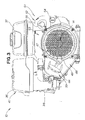
FIG. 3 is a rear view of the multipurpose engine shown inFIG. 1 ; -
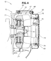
FIG. 4 is a side sectional view of the area around the generator of the multipurpose engine shown inFIG. 1 ; -
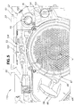
FIG. 5 is an enlarged view ofFIG. 1 ; -
FIG. 6 is a front view of the fan cover of the multipurpose engine shown inFIG. 1 ; -
FIG. 7A is a plan view showing only the first connector terminal; -
FIG. 7B is a plan view of the first connector terminal in a state in which the electrical wiring is enclosed; -
FIG. 8A is a plan view showing only the second connector terminal; -
FIG. 8B is a view of the second connector terminal in a state in which the electrical wiring is enclosed; -
FIG. 9A is a front view of the cover panel; -
FIG. 9B is a plan view of the cover panel; -
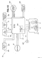
FIG. 10 is a control block diagram of the multipurpose engine shown inFIG. 1 ; -
FIG. 11A is a diagram depicting a state in which the cover panel is attached in the multipurpose engine shown inFIG. 1 ; -
FIG. 11B is a diagram depicting a state in which the cover panel is removed in the multipurpose engine shown inFIG. 1 ; -
FIG. 12 is a control block diagram of the multipurpose engine according to another embodiment; and -
FIG. 13 is a diagram depicting the conventional basic configuration. - The
multipurpose engine 10 shown inFIGS. 1 through 3 includes an enginemain body 27 and auxiliary components that are composed of accessories for operating the enginemain body 27. The auxiliary components primarily include anair cleaner 35 for drawing in outside air, acarburetor 36 for vaporizing fuel (gasoline) and feeding the fuel to acombustion chamber 29, afuel tank 37 for storing the fuel, amuffler 40 for reducing the exhaust noise from the exhaust gas, arecoil starter 39 for starting the enginemain body 27, an oil level detection device (oil alarm) 50 for detecting the oil level, aplug cap 60 that houses an ignition unit 204 (seeFIG. 10 ) for performing ignition, and other components. The enginemain body 27 shown in the drawings is an overhead-camshaft (OHC) air-cooled engine in which the cylinder is tilted. - The engine
main body 27 is provided with acrankcase 13 for storing oil (lubricant) 12, acrankshaft 14 that is rotatably mounted parallel to thecrankcase 13, a single-cylinder block 15 integrally formed with thecrankcase 13 at an angle, apiston 17 that is slidably mounted to thecylinder 16 of thecylinder block 15, aconnecting rod 18 for connecting thepiston 17 and thecrankshaft 14, acylinder head 21 mounted to theopen portion 19 of thecylinder block 15, anintake valve 24 provided to theintake port 22 of thecylinder head 21, and anexhaust valve 25 provided to theexhaust port 23 of thecylinder head 21. - The
casing 28 is composed of thecrankcase 13, thecylinder block 15, and thecylinder head 21. Thecombustion chamber 29 is composed of thecylinder block 15 and thecylinder head 21. - The
crankshaft 14 has apower takeoff unit 31 at one end thereof. Thispower takeoff unit 31 is referred to as a power take-off (PTO). - The
cylinder head 21 is provided with avalve movement chamber 32 for driving theintake valve 24 and theexhaust valve 25 through the rotation of thecrankshaft 14. -
Reference numeral 33 in the drawings indicates the oil level gauge. Anexhaust pipe 45 for discharging the exhaust gas is mounted to themuffler cover 41. - As shown in
FIG. 2 , the oil is supplied from anoil supply vent 42. One end of theexhaust duct 43 extends from thecylinder head 21. Themuffler 40 is mounted to the other end of theexhaust duct 43. Therecoil starter 39 has a starting knob (grip) 44. - As shown in
FIGS. 3 and4 , thegenerator 46 and the coolingfan 47 are mounted on opposite sides of the power take-off 31 (seeFIG. 1 ) of thecrankshaft 14. Therecoil starter 39 is covered by arecoil starter cover 49. A connecting duct (intake duct) 38 is connected to theair cleaner 35. - The
generator 46 is composed of astarter 71 that is mounted to thecylinder block 15 on the side of the other end of thecrankshaft 14, and arotor 72 that is mounted to thecrankshaft 14 around thestarter 71 and has a pulse coil (rotation detection sensor) 77 for detecting the number of revolutions of thegenerator 46. - The cooling
fan 47 is provided coaxially with the crankshaft (output shaft) 14, is mounted outside therotor 72, and is covered by afan cover 48 provided to thecylinder block 15. - The
recoil starter 39 starts the enginemain body 27. The starter is composed of arecoil starter cover 49 that is supported on the side of thecylinder block 15, apulley 74 that is rotatably mounted to thisrecoil starter cover 49, a return spring (not shown in the drawing) that returns thepulley 74 to the initial state and is provided between thepulley 74 and therecoil starter cover 49, alatch 75 for meshing with acup 73 during rotation of thepulley 74, arope 76 wrapped on thepulley 74, and a starting knob 44 (seeFIG. 3 ) mounted to the distal end of thisrope 76. Thecup 73 is mounted on the outside of the coolingfan 47. - An example of the
electrical wiring structure 110 in themultipurpose engine 10 of the present invention will be described hereinafter with reference toFIGS. 5 through 12 . - As shown in
FIG. 5 , thefuel tank 37, theair cleaner 35, the muffler 40 (FIG. 1 ), and other auxiliary components are disposed above thecylinder block 15. Anelectrical wiring bundle 103 that is routed to the generator 46 (seeFIG. 4 ) or to themain switch 101 or another electrical component is provided around thecylinder block 15. - The operating
panel 51 is composed of amain panel 52 and acover panel 53. - The
main switch 101,volume 102, and other electrical components are arranged in the elongatedmain panel 52 formed from a resin. Themain panel 52 is disposed on the upper side of therecoil starter cover 49. - A
cover panel 53 formed from a resin covers theelectrical wiring bundle 103. Thecover panel 53 is connected to themain panel 52 and is provided between thefuel tank 37 and therecoil starter cover 49. - The
main switch 101 is an electrical component for switching on the enginemain body 27, and has aswitch knob 54 for switching on the enginemain body 27. Thevolume 102 is an electrical component for adjusting the characteristics of the governor motor 203 (FIG. 10 ) of the carburetor 36 (FIG. 2 ). The volume has anadjustment knob 55. Theswitch knob 54 and theadjustment knob 55 together constitute an operating member. - A
fan cover 48 composed of a resin material is mounted on the engine main body 27 (FIG. 1 ) to cover and protect the cooling fan 47 (FIG. 5 ). - As shown in
FIG. 6 , thefan cover 48 is composed of apartition wall 106 for partitioning the cooling fan 47 (FIG. 5 ) from the recoil starter 39 (FIG. 5 ), anopening 107 formed in thepartition 106 in order to discharge hot air to the outside via the coolingfan 47, aconnector box 104 that houses the electrical wiring bundle 103 (FIG. 5 ) and is provided to the top of thepartition wall 106, and ahousing 108 that is positioned beside theconnector box 104 and encloses the main switch 101 (FIG. 5 ), thevolume 102, and other electrical components. - The
partition wall 106 is provided with afastener 111 for fastening thepartition wall 106 to the cylinder block 15 (FIG. 5 ), and a fixingboss 112 for securing the recoil starter cover 49 (FIG. 5 ). - The
connector box 104 is provided with afirst connector housing 113, and asecond connector housing 114 that is separated from thefirst connector housing 113 by a substantially U-shapedopen portion 115. The box forms a housing for the electrical wiring. Theelectrical wiring bundle 103 can be connected inside theconnector box 104. Theconnector box 104 is detachable from the cover panel 53 (FIG. 5 ). - Since the
connector box 104 is provided in integral fashion to thefan cover 48, the cost of the structure can be reduced. - As shown in
FIG. 7A , thefirst connector housing 113 is designed so as to be capable of enclosingharnesses harnesses 151 through 156. Thefirst harness 151 extends from the side of the carburetor 36 (FIG. 2 ). Thesecond harness 152 is branched from thefirst harness 151. The volume-side harness 154 is connected to thesecond harness 152. Thethird harness 153 extends from the ignition unit (ignition coil) 204 (FIG. 10 ) housed in the plug cap 60 (FIG. 2 ). The main-switch-side harness 155 is connected to thethird harness 153. Therelay harness 156 is relayed to thefirst harness 151. - The first through
third harnesses 151 through 153, the volume-side harness 154, the main-switch-side harness 155, and therelay harness 156 constitute electrical wiring. The first throughthird harnesses 151 through 153 haveplugs 161 through 163, respectively, at the distal ends thereof. The volume-side harness 154 has asocket 164 at the distal end thereof. The main-switch-side harness 155 has asocket 165 at the distal end thereof. Therelay harness 156 has asocket 166. - As shown in
FIG. 7B , thefirst connector housing 113 has afirst retainer 171 for retaining theplug 161 of the first harness 151 (FIG. 7A ), a volume-side retainer 174 for retaining thesocket 164 of the volume-side harness 154, a switch-side retainer 175 for retaining thesocket 165 of the main-switch-side harness 155, ahole 176 through which therelay harness 156 is inserted, engaging units (engaging tabs) 177 and 177 for locking the cover panel 53 (FIG. 5 ), and lockingbosses cover panel 53. - As shown in
FIG. 8A , thefirst harness 151 has aplug 181 at the other end thereof. Aseparate harness 182 extends from theplug 181. Thethird harness 153 passes through theopen portion 115 and thesecond connector housing 114. - As shown in
FIG. 8B , thesecond connector housing 114 hasretainer 183 that is shaped as an L in cross section and that supports thethird harness 153, and an I-type retainer 184 for supporting thethird harness 153. - The
second connector housing 114 has anotch 185 that opens toward theopen portion 115, for retaining the separate harness 182 (FIG. 8A ). - As shown in
FIGS. 9A and 9B , thecover panel 53 is composed of afirst cover unit 191 that is covered by the first connector housing 113 (FIG. 6 ), anopen cover unit 193 for covering the open unit 115 (FIG. 8B ), and asecond cover unit 192 for covering thesecond connector housing 114, and these cover units are integrally formed. - The
first cover unit 191 has engagingholes engaging tabs 177 and 177 (FIG. 7B ) are locked, and alocking unit 195 that corresponds to one of the locking bosses 178 (FIG. 7B ). Theopen cover unit 193 has alocking unit 196 that corresponds to theother locking boss 178. - As shown in
FIG. 9B , thesecond cover unit 192 has an expandedportion 197 that is expanded to the outside from the engine main body 27 (FIG. 1 ) and that covers theplug 181 mounted to the other end of the first harness 151 (FIG. 8A ). - As shown in
FIG. 10 , the electrical power generated by thegenerator 46 is fed to an Electronic Controlled Unit (ECU) 201. - The following types of information are received in the ECU 201: the oil level information outputted from the oil level detection device (oil alarm) 50, the information from the pulse coil (rotation detection sensor) 77 for detecting the revolutions of the
generator 46, and the information from atemperature sensor 202 for detecting the temperature of the cylinder block 15 (FIG. 1 ). The state of themain switch 101 is determined and the information from thevolume 102 for adjusting the characteristics of thegovernor motor 203 provided to the carburetor 36 (FIG. 2 ) is received. - The
ECU 201 sends ignition information to theignition coil 204 provided to the plug cap 60 (FIG. 2 ), sends throttle opening information to thegovernor motor 203, and sends drive information to afuel cutoff solenoid 205 for stopping the supply of fuel. - The
ECU 201 also includes adiagnostic unit 206 for diagnosing failures. The diagnostic results from thisdiagnostic unit 206 are displayed by a Light Emitting Diode (LED) 207. - The
generator 46,ECU 201,oil alarm 50,pulse coil 77,ignition coil 204, andfuel cutoff solenoid 205 are all electrical components. - The design properties of the multipurpose engine 10 (
FIG. 3 ) can be enhanced by covering the harnesses (electrical wiring) 151 through 156 (FIG. 11B ) as shown inFIG. 11A . Theharnesses 151 through 156 can also be prevented from being inadvertently touched, and the reliability of themultipurpose engine 10 can be enhanced. Thecover panel 53 is mounted to the fan cover 48 (FIG. 11B ) by mountingscrews - Removing the
cover panel 53 from thefan cover 48 as indicated by the arrows d1 and d1 inFIG. 11B exposes theopen portion 115 and the first andsecond connector housings 113 and 114 (FIG. 6 ) that constitute theconnector box 104. This makes it possible to focus maintenance on the electrical system of themultipurpose engine 10. - The electrical wiring is usually provided to the dead space between the cylinder block and the fuel tank, air cleaner, fuel tank, and other auxiliary components in order to protect the electrical wiring. However, since compactness is desired in the multipurpose engine, the space between the cylinder block and the fuel tank, air cleaner, fuel tank, and other auxiliary components is narrow, and the electrical wiring is difficult to connect through this space.
- In the
electrical wiring structure 110 of the multipurpose engine, connectors composed of plugs andsockets 161 through 166 for interconnecting theharnesses 151 through 156 are provided to the harnesses. Since theconnector box 104 in which theharnesses 151 through 156 are housed is provided to the side of thecylinder block 15, and theharnesses 151 through 156 are interconnected inside theconnector box 104, the connections between thegovernor motor 203,volume 102, or other electrical components shown inFIG. 10 can be concentrated inside theconnector box 104. As a result, the electrical components can be made easier to maintain, and repairs can be performed quickly. - The
connector box 104 is disposed adjacent to theswitch knob 54 by which themain switch 101 can be operated, to the adjustment knob 55 (FIG. 5 ) by which thevolume 102 can be operated, and to other operating members. It is therefore possible to verify the condition of theharnesses 151 through 156 while confirming the functioning of the operating members. As a result, convenience during maintenance can be enhanced. - Furthermore, by providing
retainers harnesses 151 through 156 in theconnector box 104, theharnesses 151 through 156 can easily be prevented from vibrating. As a result, the connections between theharnesses 151 through 156 can be made more reliable. -
FIG. 12 shows an electrical block diagram relating to the multipurpose engine according to another example. - The
multipurpose engine 210 is provided with astarter motor 211 for starting the engine main body, abattery 212 for supplying power to thisstarter motor 211, aregulator 213 interposed between thegenerator 46 and thebattery 212, and achoke motor 214 for automatically withdrawing a choke (not shown in the drawing) during startup. TheECU 201 has a port for connecting thechoke motor 214. - As described above, an example is given herein in which the
connector box 104 has afirst connector housing 113 and asecond connector housing 114, and anopen portion 115 is interposed between these first andsecond connector housings - A connector for interconnecting parts of electrical wiring is provided to the wiring itself, a connector box for housing the electrical wiring is provided beside the engine main body, and parts of the electrical wiring are interconnected inside the connector box. The present invention is therefore useful particularly in a small multipurpose engine.
Claims (3)
- A multipurpose engine (10) comprising:an engine main body (27);a generator (46) operated by the driving force of the engine;auxiliary components comprising a fuel tank, an air cleaner (35), a muffler (40), and other components (36, 37) disposed on the engine main body (27);an electrical component comprising a starter (71), a main switch (101), and the like; anda plurality of electrical wirings (103, 151, 152, 153, 154, 155, 156) for connecting the generator (46) and the electrical component to each other, whereineach of the plurality of electrical wirings (103, 151, 152, 153, 154, 155, 156) is connected inside a connector box (104) provided to the side of the engine main body (27) and disposed in a gap formed between the engine main body (27) and the auxiliary components,characterized in that the multipurpose engine further comprises:a cooling fan (47) provided coaxially with the output shaft (14) of the engine main body (27); anda fan cover (48) provided to the engine main body (27) so as to cover the cooling fan (47), whereinthe fan cover (48) is integrally formed with the connector box (104).
- The multipurpose engine of claim 1, wherein
the connector box (104) is provided in a position that is adjacent to an operating panel (51) on which the main switch (101) is mounted. - The multipurpose engine of claim 1, wherein
retainers (171, 174, 175) for retaining the plurality of electrical wirings (103) are provided to the connector box (104).
Applications Claiming Priority (2)
| Application Number | Priority Date | Filing Date | Title |
|---|---|---|---|
| JP2005183057 | 2005-06-23 | ||
| PCT/JP2006/312557 WO2006137503A2 (en) | 2005-06-23 | 2006-06-16 | Multipurpose engine |
Publications (2)
| Publication Number | Publication Date |
|---|---|
| EP1907678A2 EP1907678A2 (en) | 2008-04-09 |
| EP1907678B1 true EP1907678B1 (en) | 2014-01-15 |
Family
ID=36969181
Family Applications (1)
| Application Number | Title | Priority Date | Filing Date |
|---|---|---|---|
| EP06767207.1A Not-in-force EP1907678B1 (en) | 2005-06-23 | 2006-06-16 | Multipurpose engine |
Country Status (13)
| Country | Link |
|---|---|
| US (1) | US8174140B2 (en) |
| EP (1) | EP1907678B1 (en) |
| KR (1) | KR20080021796A (en) |
| CN (1) | CN101952570B (en) |
| AR (1) | AR054499A1 (en) |
| AU (1) | AU2006260177B2 (en) |
| BR (1) | BRPI0611991A2 (en) |
| CA (1) | CA2612370C (en) |
| ES (1) | ES2443665T3 (en) |
| MY (1) | MY144502A (en) |
| PE (1) | PE20070304A1 (en) |
| TW (1) | TWI346175B (en) |
| WO (1) | WO2006137503A2 (en) |
Families Citing this family (15)
| Publication number | Priority date | Publication date | Assignee | Title |
|---|---|---|---|---|
| USD624864S1 (en) * | 2009-04-21 | 2010-10-05 | Yamaha Motor Products Kabushiki Kaisha | Fuel tank for multipurpose engine |
| US8733072B2 (en) | 2011-11-04 | 2014-05-27 | Briggs & Stratton Corporation | Starter system for an engine |
| TWD162349S (en) * | 2013-01-25 | 2014-08-11 | 本田技研工業股份有限公司 | Fuel tank for internal combustion engine |
| JP6550672B2 (en) * | 2014-10-29 | 2019-07-31 | 三菱重工メイキエンジン株式会社 | Engine and engine specification changing method |
| USD821957S1 (en) * | 2015-12-04 | 2018-07-03 | Ningbo Jingcheng Car Industry Co, Ltd | Electric foldable device of rearview mirror for automobiles |
| JP1567484S (en) * | 2016-02-09 | 2017-01-23 | ||
| JP1562107S (en) * | 2016-06-29 | 2016-10-31 | ||
| USD833481S1 (en) * | 2016-12-19 | 2018-11-13 | Briggs & Stratton Corporation | Engine |
| USD836136S1 (en) * | 2017-02-17 | 2018-12-18 | Briggs & Stratton Corporation | Engine |
| USD829769S1 (en) | 2017-09-29 | 2018-10-02 | Briggs & Stratton Corporation | Engine |
| USD1089322S1 (en) * | 2023-06-28 | 2025-08-19 | Discovery Energy, Llc | Engine |
| USD1090635S1 (en) * | 2023-07-31 | 2025-08-26 | Northern Tool & Equipment Company, Inc. | Engine assembly |
| USD1103215S1 (en) * | 2023-07-31 | 2025-11-25 | Northern Tool & Equipment Company, Inc. | Engine assembly |
| USD1103214S1 (en) * | 2023-07-31 | 2025-11-25 | Northern Tool & Equipment Company, Inc. | Engine assembly |
| USD1099161S1 (en) * | 2023-07-31 | 2025-10-21 | Northern Tool & Equipment Company, Inc. | Engine assembly |
Family Cites Families (18)
| Publication number | Priority date | Publication date | Assignee | Title |
|---|---|---|---|---|
| US4136432A (en) * | 1977-01-13 | 1979-01-30 | Melley Energy Systems, Inc. | Mobile electric power generating systems |
| JPS63154820A (en) | 1986-12-19 | 1988-06-28 | Yanmar Diesel Engine Co Ltd | Electrical equipment parts storage device for engine |
| JPH09280071A (en) | 1996-04-09 | 1997-10-28 | Yamaha Motor Co Ltd | General-purpose engine wire harness layout structure |
| JPH10134898A (en) * | 1996-10-28 | 1998-05-22 | Asmo Co Ltd | Extraction structure for lead wire |
| JP3800373B2 (en) * | 1997-07-24 | 2006-07-26 | 本田技研工業株式会社 | Engine generator |
| JP3954700B2 (en) | 1997-09-09 | 2007-08-08 | 澤藤電機株式会社 | Motor generator |
| JP3347044B2 (en) * | 1998-01-19 | 2002-11-20 | 本田技研工業株式会社 | Portable engine working machine |
| JP2000328956A (en) * | 1999-05-20 | 2000-11-28 | Honda Motor Co Ltd | Engine generator |
| JP3903700B2 (en) * | 2000-08-16 | 2007-04-11 | スズキ株式会社 | Engine switch mounting structure for general-purpose engines |
| JP2002097963A (en) * | 2000-09-21 | 2002-04-05 | Sawafuji Electric Co Ltd | Engine generator |
| JP2002276514A (en) | 2001-03-16 | 2002-09-25 | Kubota Corp | Mounting structure for parts related to the cell starter of the inclined engine |
| US6750556B2 (en) * | 2002-03-26 | 2004-06-15 | Briggs & Stratton Power Products Group, Llc | Removable fuel tank |
| US6917121B2 (en) * | 2002-03-29 | 2005-07-12 | Yamaha Hatsudoki Kabushiki Kaisha | Power generator unit |
| CN100549384C (en) * | 2002-07-30 | 2009-10-14 | 雅马哈发动机动力产品株式会社 | Engine generator |
| US7045911B2 (en) * | 2003-12-16 | 2006-05-16 | F.G. Wilson | Electric power generation arrangement with rotary cabling guide |
| JP2006060956A (en) * | 2004-08-23 | 2006-03-02 | Sumitomo Wiring Syst Ltd | Electrical connection box |
| US7499263B2 (en) * | 2005-08-30 | 2009-03-03 | Doosan Infracore Co., Ltd. | Mobile power source cable connection system and method |
| WO2008024686A2 (en) * | 2006-08-19 | 2008-02-28 | Konop Chad O | Improved portable generator housing |
-
2006
- 2006-06-12 MY MYPI20062715A patent/MY144502A/en unknown
- 2006-06-16 WO PCT/JP2006/312557 patent/WO2006137503A2/en not_active Ceased
- 2006-06-16 KR KR1020087001519A patent/KR20080021796A/en not_active Ceased
- 2006-06-16 BR BRPI0611991-3A patent/BRPI0611991A2/en not_active IP Right Cessation
- 2006-06-16 ES ES06767207.1T patent/ES2443665T3/en active Active
- 2006-06-16 AU AU2006260177A patent/AU2006260177B2/en not_active Ceased
- 2006-06-16 US US11/922,577 patent/US8174140B2/en active Active
- 2006-06-16 EP EP06767207.1A patent/EP1907678B1/en not_active Not-in-force
- 2006-06-16 CA CA2612370A patent/CA2612370C/en not_active Expired - Fee Related
- 2006-06-16 CN CN2006800223249A patent/CN101952570B/en not_active Expired - Fee Related
- 2006-06-19 TW TW095121946A patent/TWI346175B/en not_active IP Right Cessation
- 2006-06-22 PE PE2006000711A patent/PE20070304A1/en not_active Application Discontinuation
- 2006-06-22 AR ARP060102691A patent/AR054499A1/en active IP Right Grant
Also Published As
| Publication number | Publication date |
|---|---|
| BRPI0611991A2 (en) | 2010-10-13 |
| CA2612370A1 (en) | 2006-12-28 |
| WO2006137503A2 (en) | 2006-12-28 |
| ES2443665T3 (en) | 2014-02-20 |
| CN101952570B (en) | 2012-07-25 |
| EP1907678A2 (en) | 2008-04-09 |
| PE20070304A1 (en) | 2007-03-23 |
| US20090302610A1 (en) | 2009-12-10 |
| KR20080021796A (en) | 2008-03-07 |
| CA2612370C (en) | 2010-08-31 |
| AU2006260177A1 (en) | 2006-12-28 |
| WO2006137503A3 (en) | 2010-05-27 |
| CN101952570A (en) | 2011-01-19 |
| US8174140B2 (en) | 2012-05-08 |
| AU2006260177B2 (en) | 2010-03-04 |
| TWI346175B (en) | 2011-08-01 |
| MY144502A (en) | 2011-09-30 |
| TW200712320A (en) | 2007-04-01 |
| AR054499A1 (en) | 2007-06-27 |
Similar Documents
| Publication | Publication Date | Title |
|---|---|---|
| US8174140B2 (en) | Multipurpose engine having electrical wiring connected inside connector box | |
| CN107035514B (en) | Hand-held power tool with a control device | |
| JP2014025456A (en) | Portable engine generator | |
| US5203292A (en) | Wiring arrangement for electric parts of an outboard motor | |
| JP4764264B2 (en) | General engine electrical wiring structure | |
| US5353758A (en) | Wiring arrangement for outboard motor | |
| US20030183180A1 (en) | Fluid supply mechanism for power generator | |
| US9850910B2 (en) | Portable working machine | |
| JP6916049B2 (en) | General-purpose engine | |
| EP0857618B1 (en) | Engine having offset cylinder banks | |
| EP1899691B1 (en) | Liquid level detection apparatus for engine oil | |
| JP4516488B2 (en) | General-purpose engine operation panel mounting structure | |
| US5105334A (en) | Electrical housing for an outboard motor | |
| US9303586B2 (en) | Boat propulsion device | |
| JP4528211B2 (en) | Ignition system for air-cooled engine | |
| KR100534153B1 (en) | V-type Diesel Engine | |
| BRPI0611991B1 (en) | GENERAL PURPOSE ENGINE | |
| JP2024074479A (en) | Engine with electrical parts box | |
| US6082312A (en) | Hand-guided appliance with an internal combustion engine with direct electronic injection | |
| JPH09280071A (en) | General-purpose engine wire harness layout structure | |
| JP4785624B2 (en) | Internal combustion engine having an electrical holder | |
| JP2007182893A (en) | Vehicle engine control unit mounting device | |
| JP2011058473A (en) | Flywheel cover attachment structure for outboard motor | |
| JPH08223856A (en) | Motor mount mounting structure | |
| JPH08223853A (en) | Engine generator |
Legal Events
| Date | Code | Title | Description |
|---|---|---|---|
| PUAI | Public reference made under article 153(3) epc to a published international application that has entered the european phase |
Free format text: ORIGINAL CODE: 0009012 |
|
| 17P | Request for examination filed |
Effective date: 20071219 |
|
| AK | Designated contracting states |
Kind code of ref document: A2 Designated state(s): AT BE BG CH CY CZ DE DK EE ES FI FR GB GR HU IE IS IT LI LT LU LV MC NL PL PT RO SE SI SK TR |
|
| AX | Request for extension of the european patent |
Extension state: AL BA HR MK RS |
|
| DAX | Request for extension of the european patent (deleted) | ||
| RBV | Designated contracting states (corrected) |
Designated state(s): DE ES FR GB IT SE |
|
| R17D | Deferred search report published (corrected) |
Effective date: 20100527 |
|
| GRAP | Despatch of communication of intention to grant a patent |
Free format text: ORIGINAL CODE: EPIDOSNIGR1 |
|
| INTG | Intention to grant announced |
Effective date: 20130902 |
|
| GRAS | Grant fee paid |
Free format text: ORIGINAL CODE: EPIDOSNIGR3 |
|
| GRAA | (expected) grant |
Free format text: ORIGINAL CODE: 0009210 |
|
| AK | Designated contracting states |
Kind code of ref document: B1 Designated state(s): DE ES FR GB IT SE |
|
| REG | Reference to a national code |
Ref country code: GB Ref legal event code: FG4D |
|
| REG | Reference to a national code |
Ref country code: ES Ref legal event code: FG2A Ref document number: 2443665 Country of ref document: ES Kind code of ref document: T3 Effective date: 20140220 |
|
| REG | Reference to a national code |
Ref country code: DE Ref legal event code: R096 Ref document number: 602006040086 Country of ref document: DE Effective date: 20140227 |
|
| REG | Reference to a national code |
Ref country code: SE Ref legal event code: TRGR |
|
| PGFP | Annual fee paid to national office [announced via postgrant information from national office to epo] |
Ref country code: GB Payment date: 20140618 Year of fee payment: 9 |
|
| PGFP | Annual fee paid to national office [announced via postgrant information from national office to epo] |
Ref country code: IT Payment date: 20140530 Year of fee payment: 9 Ref country code: ES Payment date: 20140416 Year of fee payment: 9 Ref country code: DE Payment date: 20140331 Year of fee payment: 9 Ref country code: SE Payment date: 20140624 Year of fee payment: 9 |
|
| REG | Reference to a national code |
Ref country code: DE Ref legal event code: R097 Ref document number: 602006040086 Country of ref document: DE |
|
| PLBE | No opposition filed within time limit |
Free format text: ORIGINAL CODE: 0009261 |
|
| STAA | Information on the status of an ep patent application or granted ep patent |
Free format text: STATUS: NO OPPOSITION FILED WITHIN TIME LIMIT |
|
| PGFP | Annual fee paid to national office [announced via postgrant information from national office to epo] |
Ref country code: FR Payment date: 20140619 Year of fee payment: 9 |
|
| 26N | No opposition filed |
Effective date: 20141016 |
|
| REG | Reference to a national code |
Ref country code: DE Ref legal event code: R097 Ref document number: 602006040086 Country of ref document: DE Effective date: 20141016 |
|
| REG | Reference to a national code |
Ref country code: DE Ref legal event code: R119 Ref document number: 602006040086 Country of ref document: DE |
|
| PG25 | Lapsed in a contracting state [announced via postgrant information from national office to epo] |
Ref country code: IT Free format text: LAPSE BECAUSE OF NON-PAYMENT OF DUE FEES Effective date: 20150616 |
|
| REG | Reference to a national code |
Ref country code: SE Ref legal event code: EUG |
|
| GBPC | Gb: european patent ceased through non-payment of renewal fee |
Effective date: 20150616 |
|
| PG25 | Lapsed in a contracting state [announced via postgrant information from national office to epo] |
Ref country code: SE Free format text: LAPSE BECAUSE OF NON-PAYMENT OF DUE FEES Effective date: 20150617 |
|
| REG | Reference to a national code |
Ref country code: FR Ref legal event code: ST Effective date: 20160229 |
|
| PG25 | Lapsed in a contracting state [announced via postgrant information from national office to epo] |
Ref country code: GB Free format text: LAPSE BECAUSE OF NON-PAYMENT OF DUE FEES Effective date: 20150616 Ref country code: DE Free format text: LAPSE BECAUSE OF NON-PAYMENT OF DUE FEES Effective date: 20160101 |
|
| PG25 | Lapsed in a contracting state [announced via postgrant information from national office to epo] |
Ref country code: FR Free format text: LAPSE BECAUSE OF NON-PAYMENT OF DUE FEES Effective date: 20150630 |
|
| REG | Reference to a national code |
Ref country code: ES Ref legal event code: FD2A Effective date: 20160727 |
|
| PG25 | Lapsed in a contracting state [announced via postgrant information from national office to epo] |
Ref country code: ES Free format text: LAPSE BECAUSE OF NON-PAYMENT OF DUE FEES Effective date: 20150617 |