EP1906435A2 - Compact par lamp - Google Patents
Compact par lamp Download PDFInfo
- Publication number
- EP1906435A2 EP1906435A2 EP07115134A EP07115134A EP1906435A2 EP 1906435 A2 EP1906435 A2 EP 1906435A2 EP 07115134 A EP07115134 A EP 07115134A EP 07115134 A EP07115134 A EP 07115134A EP 1906435 A2 EP1906435 A2 EP 1906435A2
- Authority
- EP
- European Patent Office
- Prior art keywords
- reflector
- longitudinal axis
- light source
- par lamp
- compact
- Prior art date
- Legal status (The legal status is an assumption and is not a legal conclusion. Google has not performed a legal analysis and makes no representation as to the accuracy of the status listed.)
- Withdrawn
Links
- 239000002775 capsule Substances 0.000 claims abstract description 18
- 238000010891 electric arc Methods 0.000 claims abstract description 4
- 230000003287 optical effect Effects 0.000 description 3
- 230000007423 decrease Effects 0.000 description 2
- 239000011521 glass Substances 0.000 description 2
- 239000005388 borosilicate glass Substances 0.000 description 1
- 230000000694 effects Effects 0.000 description 1
- 229910052736 halogen Inorganic materials 0.000 description 1
- 229910052751 metal Inorganic materials 0.000 description 1
- 239000002184 metal Substances 0.000 description 1
- 229910001507 metal halide Inorganic materials 0.000 description 1
- 150000005309 metal halides Chemical class 0.000 description 1
- 238000012986 modification Methods 0.000 description 1
- 230000004048 modification Effects 0.000 description 1
- 150000003839 salts Chemical class 0.000 description 1
- 230000007704 transition Effects 0.000 description 1
- 229910052721 tungsten Inorganic materials 0.000 description 1
- 239000010937 tungsten Substances 0.000 description 1
- -1 tungsten halogen Chemical class 0.000 description 1
Images

Classifications
-
- H—ELECTRICITY
- H01—ELECTRIC ELEMENTS
- H01J—ELECTRIC DISCHARGE TUBES OR DISCHARGE LAMPS
- H01J61/00—Gas-discharge or vapour-discharge lamps
- H01J61/02—Details
- H01J61/30—Vessels; Containers
- H01J61/34—Double-wall vessels or containers
-
- F—MECHANICAL ENGINEERING; LIGHTING; HEATING; WEAPONS; BLASTING
- F21—LIGHTING
- F21V—FUNCTIONAL FEATURES OR DETAILS OF LIGHTING DEVICES OR SYSTEMS THEREOF; STRUCTURAL COMBINATIONS OF LIGHTING DEVICES WITH OTHER ARTICLES, NOT OTHERWISE PROVIDED FOR
- F21V7/00—Reflectors for light sources
- F21V7/04—Optical design
- F21V7/09—Optical design with a combination of different curvatures
-
- H—ELECTRICITY
- H01—ELECTRIC ELEMENTS
- H01J—ELECTRIC DISCHARGE TUBES OR DISCHARGE LAMPS
- H01J61/00—Gas-discharge or vapour-discharge lamps
- H01J61/02—Details
- H01J61/025—Associated optical elements
-
- H—ELECTRICITY
- H01—ELECTRIC ELEMENTS
- H01K—ELECTRIC INCANDESCENT LAMPS
- H01K1/00—Details
- H01K1/28—Envelopes; Vessels
- H01K1/34—Double wall vessels
Definitions
- This invention relates to electric lamps and more particularly to lamps having a parabolic reflector (PAR lamps). Still more particularly, it relates to compact PAR lamps such as those having major diameters of 2.5 inches or less.
- PAR lamps such as those having major diameters of 2.5 inches or less.
- PAR lamps are typically comprised of a light source such as a tungsten halogen capsule or a high intensity discharge (HID) arc tube mounted within a glass body with a parabolic reflector therein.
- the glass body can be pressed borosilicate glass.
- a lens usually covers the front or light-emitting end of the body and can contain optical elements to provide a desired beam shape (for example, a spot or flood beam).
- General service PAR lamps usually have a neck region between the parabolic reflector and the base, and the base generally comprises a threaded fitting for connecting the lamp to a power source via a socket.
- the usual power source is 100 to 240 volts.
- the neck provides the mechanical support between the reflector optical portion and the base electrical portion.
- the neck additionally provides room for the capsule press seal, the lead-ins, capsule mounting components, and wiring and separates the light source (i.e., the filament or arc discharge) from the base to reduce the base temperature.
- Yet another object of the invention is a compact PAR lamp having a spot beam.
- a compact PAR lamp comprising: a hollow body arrayed along a longitudinal axis and having an open end and a substantially closed neck end and containing a light source capsule within said hollow body and coaxial with said longitudinal axis, said light source capsule having electrical lead-ins extending therefrom and exiting via said neck end; a first parabolic reflector formed within said body having a wide portion adjacent said open end and a narrow portion spaced therefrom along said longitudinal axis; a second reflector formed within said body and extending from said narrow portion into said neck end; a lens closing said open; and a base attached to said closed neck end.
- the secondary reflecting surface substantially reduces the amount of light entering the neck region and directs more of the light into the beam.
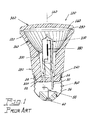
- Fig. 1 is an elevational cross section of a prior art lamp
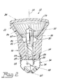
- Fig. 2 is an elevational cross section of an embodiment of the invention.
- Fig. 3 is a similar view of an alternate embodiment of the invention.
- a prior art PAR lamp 100 having a body 120 arrayed along a longitudinal axis 140.
- the body 120 has an open end 160 and a substantially closed neck end 180 and contains a light capsule 200.
- the light source capsule 200 contains an incandescent filament 380 arrayed along the longitudinal axis 140 and having lead-ins 220 and 240 extending from the capsule 200 for appropriate electrical connection to a base 360.
- a parabolic reflector 260 having a wide portion 280 and a narrow portion 300 is formed within the body 120 and a lens 340 closes the open end 160.
- Lamps of this description are generally available under the designations PAR 16 or PAR 20 depending upon the major diameter of the bulb: however, such lamps have relatively poor efficiency and center beam intensity, especially with the spot beam angle. PAR 16 lamps are typically available only in flood beam angle.
- a compact PAR lamp 10 has a hollow body 12 arrayed along a longitudinal axis 14.
- the body 12 has an open end 16 and a substantially closed neck end 18.
- a light source capsule 20 is positioned with the body 12 and is coaxial with the axis 14.
- the capsule 20 in this instance contains an incandescent filament 38 that is arrayed along the longitudinal axis 14 and has a first end 40 and a second end 42.
- Electrical lead-ins 22, 24 connect the filament and extend from the capsule 20 and exit the body 12 via the neck end 18.
- a first parabolic reflector 26 is formed within the hollow body 12 and has a wide portion 28 adjacent the open end 16 and a narrow portion 30 spaced therefrom along the longitudinal axis 14.
- a second reflector 32 is formed within the body 12 and extends from the narrow portion 30 into the neck end 18,
- a lens 34 closes the open end 16 and a base 36 is attached to and closes the neck end 18.
- the second reflector 32 is ellipsoidal; however, the second reflector also could be spherical.
- the focus points of the ellipse will coincide with the first and second ends 40, 42 of the filament 38. If the second reflector 32 is spherical, the center point thereof will coincide with or be near the parabolic focal point.
- Optical ray trace modeling was used to estimate the effect of adding an elliptical second reflector to a PAR 20 reflector.
- the modeling predicted a 6% percent lumen increase and a 13% increase in center beam intensity. Additionally, a significant increase in radiated power returned to the coil was predicted and such an increase would further improve lamp efficiency.
- the light source 20 comprises an arc discharge vessel 44 containing electrodes 46, 48 having termini 46', 48' defining an arc gap 50 therebetween and the focal points of the ellipsoid second reflector 32 correspond with the termini 46', 48'.
- this provides all of the light emission above the neck opening.
- Further benefits are also provided by this approach since, when but a single reflector surface is used, the arc tube wall temperature can be too cold to achieve optimum vapor pressure of the salts that are used in low wattage metal halide lamps.
- the surface of the secondary reflector 32 returns additional radiated power to the arc tube 44 that increases wall temperature to raise the vapor pressure. Further, the second reflector 32 directs radiated power away from the seal areas, thus reducing the chance of seal failures.
- the capsule 20 is supported by a lead-in (for example, 24) that is welded or otherwise affixed to an inner tab 50 of a metal clip 52.
- the outer tabs 54 of the clip 52 contact the screw portion 56 of the base 36.
- One end of a small diameter fuse wire 58 is welded to the other lead-in (22, in this instance) and the other end of the fuse wire 58 is soldered or otherwise affixed to the center eyelet 60.
Landscapes
- Engineering & Computer Science (AREA)
- General Engineering & Computer Science (AREA)
- Non-Portable Lighting Devices Or Systems Thereof (AREA)
- Fastening Of Light Sources Or Lamp Holders (AREA)
Abstract
Description
- TECHNICAL FIELD
- This invention relates to electric lamps and more particularly to lamps having a parabolic reflector (PAR lamps). Still more particularly, it relates to compact PAR lamps such as those having major diameters of 2.5 inches or less.
- BACKGROUND ART
- PAR lamps are typically comprised of a light source such as a tungsten halogen capsule or a high intensity discharge (HID) arc tube mounted within a glass body with a parabolic reflector therein. The glass body can be pressed borosilicate glass. A lens usually covers the front or light-emitting end of the body and can contain optical elements to provide a desired beam shape (for example, a spot or flood beam). General service PAR lamps usually have a neck region between the parabolic reflector and the base, and the base generally comprises a threaded fitting for connecting the lamp to a power source via a socket. The usual power source is 100 to 240 volts. The neck provides the mechanical support between the reflector optical portion and the base electrical portion. The neck additionally provides room for the capsule press seal, the lead-ins, capsule mounting components, and wiring and separates the light source (i.e., the filament or arc discharge) from the base to reduce the base temperature.
- Much of the light that enters the neck opening of PAR lamps is lost due to multiple reflection and absorbtion by the mount and capsule components and does not contribute to the beam. It is known that the neck opening cross-sectional area should be as small as possible to maximize beam intensity and lamp efficiency (determined by dividing lamp lumens by source lumens). The marketplace demands compact lamps with small diameter aperture such as
PAR 16 andPAR 20 size lamps; however, as lamp diameter and reflector focal length decrease, the light loss in the neck area becomes substantial. Lumen output and center beam candle power (CBCP) fall off rapidly as PAR lamp size decreases and it is very difficult to design aPAR 16 spot lamp with acceptable performance. At this point in time,PAR 16 lamps are available only in a flood beam angle where the light center can be positioned ahead of the focus and away from the neck opening without an unacceptable loss in center beam intensity. - DISCLOSURE OF INVENTION
- It is, therefore, an object of the present invention to obviate the disadvantages of the prior art.
- It is another object of the invention to enhance compact PAR lamps,
- Yet another object of the invention is a compact PAR lamp having a spot beam.
- These objects are accomplished, in one aspect of the invention, by a compact PAR lamp comprising: a hollow body arrayed along a longitudinal axis and having an open end and a substantially closed neck end and containing a light source capsule within said hollow body and coaxial with said longitudinal axis, said light source capsule having electrical lead-ins extending therefrom and exiting via said neck end; a first parabolic reflector formed within said body having a wide portion adjacent said open end and a narrow portion spaced therefrom along said longitudinal axis; a second reflector formed within said body and extending from said narrow portion into said neck end; a lens closing said open; and a base attached to said closed neck end. The secondary reflecting surface substantially reduces the amount of light entering the neck region and directs more of the light into the beam.
- BRIEF DESCRIPTION OF THE DRAWINGS
- Fig. 1 is an elevational cross section of a prior art lamp,
- Fig. 2 is an elevational cross section of an embodiment of the invention; and
- Fig. 3 is a similar view of an alternate embodiment of the invention.
- BEST MODE FOR CARRYING OUT THE INVENTION
- For a better understanding of the present invention, together with other and further objects, advantages and capabilities thereof, reference is made to the following disclosure and appended claims taken in conjunction with the above-described drawings.
- Referring now to the drawings with greater particularity, there is shown in Fig. 1 a prior
art PAR lamp 100 having abody 120 arrayed along alongitudinal axis 140. Thebody 120 has anopen end 160 and a substantially closedneck end 180 and contains alight capsule 200. As shown thelight source capsule 200 contains anincandescent filament 380 arrayed along thelongitudinal axis 140 and having lead-ins capsule 200 for appropriate electrical connection to abase 360. Aparabolic reflector 260 having awide portion 280 and anarrow portion 300 is formed within thebody 120 and alens 340 closes theopen end 160. - Lamps of this description are generally available under the designations PAR 16 or PAR 20 depending upon the major diameter of the bulb: however, such lamps have relatively poor efficiency and center beam intensity, especially with the spot beam angle.
PAR 16 lamps are typically available only in flood beam angle. - To remedy this problem and provide a compact PAR lamp with an acceptable spot beam the lamp shown in Fig. 2 is provided. Therein, a
compact PAR lamp 10 has ahollow body 12 arrayed along alongitudinal axis 14. Thebody 12 has anopen end 16 and a substantially closedneck end 18. Alight source capsule 20 is positioned with thebody 12 and is coaxial with theaxis 14. Thecapsule 20 in this instance contains anincandescent filament 38 that is arrayed along thelongitudinal axis 14 and has afirst end 40 and asecond end 42. Electrical lead-ins capsule 20 and exit thebody 12 via theneck end 18. - A first
parabolic reflector 26 is formed within thehollow body 12 and has a wide portion 28 adjacent theopen end 16 and anarrow portion 30 spaced therefrom along thelongitudinal axis 14. Asecond reflector 32 is formed within thebody 12 and extends from thenarrow portion 30 into theneck end 18, Alens 34 closes theopen end 16 and abase 36 is attached to and closes theneck end 18. - In a preferred embodiment of the invention the
second reflector 32 is ellipsoidal; however, the second reflector also could be spherical. When thesecond reflector 32 is ellipsoidal the focus points of the ellipse will coincide with the first andsecond ends filament 38. If thesecond reflector 32 is spherical, the center point thereof will coincide with or be near the parabolic focal point. - The advantages of the invention will be seen from a comparison of Figs. 1 and 2. In both instances the center of the
filament 38 is positioned at the parabolic focal point. In the prior art lamp of Fig. 1 this positioning mandates that nearly 30% of the filament length is below the neck opening; however, with the version shown in Fig. 2 the entire filament length is well above the neck opening. This second reflector surface additionally provides a transition zone between the thick wall of the neck and the thinner wall of the parabolic reflector. This feature reduces envelope weight and improves manufacturability. - Optical ray trace modeling was used to estimate the effect of adding an elliptical second reflector to a
PAR 20 reflector. The modeling predicted a 6% percent lumen increase and a 13% increase in center beam intensity. Additionally, a significant increase in radiated power returned to the coil was predicted and such an increase would further improve lamp efficiency. - In practice the new design incorporated into
PAR 20 lamps with operating parameters of 50W/120V, has been found to provide a 3.4% lumen increase and a 12% increase in center beam intensity, a good agreement with the ray trace mode. - When the new design is incorporated into the
smaller PAR 16 lamp, the benefits are even greater, resulting in a measured 12% higher lumen output and 35% greater center beam intensity than prior art lamps with but a single parabolic reflecting surface. - Also, these benefits are achievable with PAR lamps employing arc tubes as the light source.
- Such an example is shown in Fig. 3, wherein the
light source 20 comprises an arc discharge vessel 44 containingelectrodes arc gap 50 therebetween and the focal points of the ellipsoidsecond reflector 32 correspond with the termini 46', 48'. Again, this provides all of the light emission above the neck opening. Further benefits are also provided by this approach since, when but a single reflector surface is used, the arc tube wall temperature can be too cold to achieve optimum vapor pressure of the salts that are used in low wattage metal halide lamps. The surface of thesecondary reflector 32 returns additional radiated power to the arc tube 44 that increases wall temperature to raise the vapor pressure. Further, thesecond reflector 32 directs radiated power away from the seal areas, thus reducing the chance of seal failures. - In the lamps shown herein the
capsule 20 is supported by a lead-in (for example, 24) that is welded or otherwise affixed to aninner tab 50 of ametal clip 52. Theouter tabs 54 of theclip 52 contact thescrew portion 56 of thebase 36. One end of a smalldiameter fuse wire 58 is welded to the other lead-in (22, in this instance) and the other end of thefuse wire 58 is soldered or otherwise affixed to thecenter eyelet 60. - While there have been shown and described what are at present considered to be the preferred embodiments of the invention, it will be apparent to those skilled in the art that various changes and modifications can be made herein without departing from the scope of the invention as defined by the appended claims.
Claims (6)
- A compact PAR lamp comprising:a hollow body arrayed along a longitudinal axis and having an open end and a substantially closed neck end and containing a light source capsule within said hollow body and coaxial with said longitudinal axis, said light source capsule having electrical lead-ins extending therefrom and exiting via said neck end;a first parabolic reflector formed within said body having a wide portion adjacent said open end and a narrow portion spaced therefrom along said longitudinal axis;a second reflector formed within said body and extending from said narrow portion into said neck end;a lens closing said open; anda base attached to said closed neck end.
- The compact PAR lamp of Claim 1 wherein said second reflector is an ellipsoid.
- The compact PAR lamp of Claim 2 wherein said light source capsule includes an incandescent filament arrayed along said longitudinal axis and having a first end and a second end, the focal points of said ellipsoid corresponding with said first end and said second end of said filament.
- The compact PAR lamp of Claim 2 wherein said light source comprises and an arc discharge vessel containing electrodes having termini defining an arc gap therebetween and the focal points of said ellipsoid correspond with said termini.
- The compact PAR lamp of Claim 1 wherein said second reflector is spherical.
- The compact PAR lamp of Claim 5 wherein a center point of said spherical reflector coincides with the focal point of said parabolic reflector.
Applications Claiming Priority (1)
| Application Number | Priority Date | Filing Date | Title |
|---|---|---|---|
| US11/528,040 US7518299B2 (en) | 2006-09-27 | 2006-09-27 | Compact PAR lamp comprising an ellipsoid reflector having more than one focal point |
Publications (2)
| Publication Number | Publication Date |
|---|---|
| EP1906435A2 true EP1906435A2 (en) | 2008-04-02 |
| EP1906435A3 EP1906435A3 (en) | 2010-11-24 |
Family
ID=38941898
Family Applications (1)
| Application Number | Title | Priority Date | Filing Date |
|---|---|---|---|
| EP07115134A Withdrawn EP1906435A3 (en) | 2006-09-27 | 2007-08-28 | Compact par lamp |
Country Status (5)
| Country | Link |
|---|---|
| US (1) | US7518299B2 (en) |
| EP (1) | EP1906435A3 (en) |
| JP (1) | JP2008084863A (en) |
| CN (1) | CN101153699B (en) |
| TW (1) | TW200826149A (en) |
Families Citing this family (1)
| Publication number | Priority date | Publication date | Assignee | Title |
|---|---|---|---|---|
| CN103032796B (en) * | 2012-12-11 | 2015-04-22 | 安徽华东光电技术研究所 | Aircraft refueling lamp and processing method thereof |
Family Cites Families (18)
| Publication number | Priority date | Publication date | Assignee | Title |
|---|---|---|---|---|
| FR2465313B1 (en) * | 1979-09-17 | 1986-04-11 | Duro Test Corp | ELLIPSOIDAL ENCLOSURE FOR INCANDESCENT LAMPS, INCLUDING MEANS FOR RETURNING INFRARED ENERGY |
| US4420800A (en) * | 1980-12-22 | 1983-12-13 | General Electric Company | Reflector lamp with shaped reflector and lens |
| US4484254A (en) * | 1982-05-21 | 1984-11-20 | Gte Products Corporation | PAR Flood lamp |
| US4473872A (en) * | 1982-05-21 | 1984-09-25 | Gte Products Corporation | Par spot lamp |
| US4494176A (en) * | 1984-03-14 | 1985-01-15 | General Electric Company | Lamps having multiple and aimed parabolic sections for increased useful light output |
| US5199787A (en) * | 1992-01-08 | 1993-04-06 | North American Philips Corporation | Reflector lamp having improved lens |
| US6201348B1 (en) * | 1998-02-20 | 2001-03-13 | Osram Sylvania Inc. | Capacitive coupling starting aid for metal halide lamp |
| US6586864B2 (en) * | 1998-05-21 | 2003-07-01 | General Electric Company | Reflector lamp having a reflecting section with faceted surfaces |
| US6252338B1 (en) * | 1998-05-21 | 2001-06-26 | General Electric Company | Reflector lamp having a reflecting section with faceted surfaces |
| US6086227A (en) * | 1998-09-11 | 2000-07-11 | Osram Sylvania Inc. | Lamp with faceted reflector and spiral lens |
| US6329742B1 (en) * | 1999-06-02 | 2001-12-11 | Philips Electronics North America Corp. | Metal halide lamp with metal frame supporting a protective sleeve |
| US6168293B1 (en) * | 1999-08-09 | 2001-01-02 | General Electric Company | Spot par reflector lamp |
| US20050018432A1 (en) * | 2003-07-25 | 2005-01-27 | Buschmann Jeffrey P. | Reflector lamp with a high domed lens |
| US7131749B2 (en) * | 2003-08-21 | 2006-11-07 | Randal Lee Wimberly | Heat distributing hybrid reflector lamp or illumination system |
| US7030543B2 (en) * | 2004-02-24 | 2006-04-18 | Osram Sylvania Inc. | Reflector lamp having reduced seal temperature |
| US7125149B2 (en) * | 2004-03-15 | 2006-10-24 | Osram Sylvania Inc. | Reflector lamp with reduced seal temperature |
| JP4402539B2 (en) * | 2004-08-06 | 2010-01-20 | パナソニック株式会社 | Metal halide lamp and lighting device using the same |
| US7527396B2 (en) * | 2005-06-21 | 2009-05-05 | Osram Sylvania Inc. | Illumination device with thermally isolated integral power supply |
-
2006
- 2006-09-27 US US11/528,040 patent/US7518299B2/en not_active Expired - Fee Related
-
2007
- 2007-08-28 EP EP07115134A patent/EP1906435A3/en not_active Withdrawn
- 2007-09-26 TW TW096135643A patent/TW200826149A/en unknown
- 2007-09-26 JP JP2007249245A patent/JP2008084863A/en not_active Ceased
- 2007-09-27 CN CN2007101629171A patent/CN101153699B/en not_active Expired - Fee Related
Non-Patent Citations (1)
| Title |
|---|
| None * |
Also Published As
| Publication number | Publication date |
|---|---|
| US7518299B2 (en) | 2009-04-14 |
| JP2008084863A (en) | 2008-04-10 |
| CN101153699B (en) | 2011-03-30 |
| EP1906435A3 (en) | 2010-11-24 |
| TW200826149A (en) | 2008-06-16 |
| US20080074024A1 (en) | 2008-03-27 |
| CN101153699A (en) | 2008-04-02 |
Similar Documents
| Publication | Publication Date | Title |
|---|---|---|
| US8721127B2 (en) | Lighting apparatus with reflector rotatably coupled to an adapter | |
| RU2443937C2 (en) | Gas-discharge tube of high intensity for directional light | |
| US20100277922A1 (en) | Lighting apparatus | |
| US7178944B2 (en) | Lighting apparatus | |
| JPH11508402A (en) | Reflective lamp | |
| US20100246188A1 (en) | lighting apparatus | |
| US7390106B2 (en) | Lighting apparatus | |
| US20100181892A1 (en) | Lighting apparatus | |
| US7518299B2 (en) | Compact PAR lamp comprising an ellipsoid reflector having more than one focal point | |
| JP4229985B2 (en) | Light bulb with reflective film | |
| US7748871B2 (en) | Lighting apparatus | |
| JP2006059813A (en) | Incandescent light bulb for headlight | |
| JPH097553A (en) | Incandescent light bulb and lighting device using the same | |
| JP2008226814A (en) | Light bulb-type fluorescent lamp and lighting fixture | |
| JP2008004398A (en) | Light bulb-type fluorescent lamp and lighting fixture | |
| RU2464491C2 (en) | Large par lamp demonstrating superb light with higher efficiency and extended service life | |
| JP2006059826A (en) | Halogen bulb with reflector | |
| US20090323350A1 (en) | High-intensity discharge lamp for spot lighting | |
| CN100578071C (en) | Bulb-shaped fluorescent lamp and lighting fixture | |
| CN101110344A (en) | Electric lamps with infrared reflective coating | |
| JPH0432497B2 (en) | ||
| JP2008010382A (en) | Light source device | |
| JP2006080015A (en) | Fluorescent lamp device and lighting apparatus | |
| JP4536753B2 (en) | Tube with bulb and reflector | |
| JP2006202668A (en) | Fluorescent lamp, fluorescent lamp device and lighting fixture |
Legal Events
| Date | Code | Title | Description |
|---|---|---|---|
| PUAI | Public reference made under article 153(3) epc to a published international application that has entered the european phase |
Free format text: ORIGINAL CODE: 0009012 |
|
| AK | Designated contracting states |
Kind code of ref document: A2 Designated state(s): AT BE BG CH CY CZ DE DK EE ES FI FR GB GR HU IE IS IT LI LT LU LV MC MT NL PL PT RO SE SI SK TR |
|
| AX | Request for extension of the european patent |
Extension state: AL BA HR MK YU |
|
| PUAL | Search report despatched |
Free format text: ORIGINAL CODE: 0009013 |
|
| AK | Designated contracting states |
Kind code of ref document: A3 Designated state(s): AT BE BG CH CY CZ DE DK EE ES FI FR GB GR HU IE IS IT LI LT LU LV MC MT NL PL PT RO SE SI SK TR |
|
| AX | Request for extension of the european patent |
Extension state: AL BA HR MK RS |
|
| RIC1 | Information provided on ipc code assigned before grant |
Ipc: H01J 61/02 20060101AFI20101020BHEP Ipc: H01J 61/34 20060101ALI20101020BHEP Ipc: H01K 1/34 20060101ALI20101020BHEP Ipc: F21V 7/09 20060101ALI20101020BHEP |
|
| 17P | Request for examination filed |
Effective date: 20101220 |
|
| AKX | Designation fees paid |
Designated state(s): DE FR GB |
|
| 17Q | First examination report despatched |
Effective date: 20160708 |
|
| STAA | Information on the status of an ep patent application or granted ep patent |
Free format text: STATUS: EXAMINATION IS IN PROGRESS |
|
| RAP1 | Party data changed (applicant data changed or rights of an application transferred) |
Owner name: LEDVANCE LLC |
|
| GRAP | Despatch of communication of intention to grant a patent |
Free format text: ORIGINAL CODE: EPIDOSNIGR1 |
|
| STAA | Information on the status of an ep patent application or granted ep patent |
Free format text: STATUS: GRANT OF PATENT IS INTENDED |
|
| INTG | Intention to grant announced |
Effective date: 20180723 |
|
| STAA | Information on the status of an ep patent application or granted ep patent |
Free format text: STATUS: THE APPLICATION IS DEEMED TO BE WITHDRAWN |
|
| 18D | Application deemed to be withdrawn |
Effective date: 20181204 |