EP1905959A2 - Variable pitch wedge retention in vane outer base - Google Patents
Variable pitch wedge retention in vane outer base Download PDFInfo
- Publication number
- EP1905959A2 EP1905959A2 EP07253600A EP07253600A EP1905959A2 EP 1905959 A2 EP1905959 A2 EP 1905959A2 EP 07253600 A EP07253600 A EP 07253600A EP 07253600 A EP07253600 A EP 07253600A EP 1905959 A2 EP1905959 A2 EP 1905959A2
- Authority
- EP
- European Patent Office
- Prior art keywords
- cavity
- outer base
- vane
- wedge
- turbine engine
- Prior art date
- Legal status (The legal status is an assumption and is not a legal conclusion. Google has not performed a legal analysis and makes no representation as to the accuracy of the status listed.)
- Granted
Links
- 230000014759 maintenance of location Effects 0.000 title description 15
- 238000000034 method Methods 0.000 claims abstract description 14
- 230000000717 retained effect Effects 0.000 claims abstract description 5
- 239000000853 adhesive Substances 0.000 claims description 13
- 230000001070 adhesive effect Effects 0.000 claims description 13
- 239000000463 material Substances 0.000 claims description 13
- 239000002131 composite material Substances 0.000 claims description 9
- 239000004593 Epoxy Substances 0.000 claims description 7
- 239000007769 metal material Substances 0.000 claims description 3
- 229920000049 Carbon (fiber) Polymers 0.000 claims description 2
- 239000004677 Nylon Substances 0.000 claims description 2
- 239000004697 Polyetherimide Substances 0.000 claims description 2
- 239000004917 carbon fiber Substances 0.000 claims description 2
- 150000001875 compounds Chemical class 0.000 claims description 2
- 239000003822 epoxy resin Substances 0.000 claims description 2
- 239000003365 glass fiber Substances 0.000 claims description 2
- VNWKTOKETHGBQD-UHFFFAOYSA-N methane Chemical compound C VNWKTOKETHGBQD-UHFFFAOYSA-N 0.000 claims description 2
- 238000000465 moulding Methods 0.000 claims description 2
- 229920001778 nylon Polymers 0.000 claims description 2
- 229920000647 polyepoxide Polymers 0.000 claims description 2
- 229920001601 polyetherimide Polymers 0.000 claims description 2
- 239000004814 polyurethane Substances 0.000 claims description 2
- 229920002635 polyurethane Polymers 0.000 claims description 2
- 230000002787 reinforcement Effects 0.000 claims description 2
- 239000003677 Sheet moulding compound Substances 0.000 description 2
- 230000000712 assembly Effects 0.000 description 2
- 238000000429 assembly Methods 0.000 description 2
- 239000011152 fibreglass Substances 0.000 description 2
- 230000004048 modification Effects 0.000 description 2
- 238000012986 modification Methods 0.000 description 2
- 239000004033 plastic Substances 0.000 description 2
- 229920003023 plastic Polymers 0.000 description 2
- 229920004738 ULTEM® Polymers 0.000 description 1
- 230000015556 catabolic process Effects 0.000 description 1
- 238000006731 degradation reaction Methods 0.000 description 1
- 239000000835 fiber Substances 0.000 description 1
- 238000007689 inspection Methods 0.000 description 1
- 238000009434 installation Methods 0.000 description 1
- 239000002184 metal Substances 0.000 description 1
- 230000008569 process Effects 0.000 description 1
- 230000003014 reinforcing effect Effects 0.000 description 1
- 230000008439 repair process Effects 0.000 description 1
- 230000007704 transition Effects 0.000 description 1
Images

Classifications
-
- F—MECHANICAL ENGINEERING; LIGHTING; HEATING; WEAPONS; BLASTING
- F04—POSITIVE - DISPLACEMENT MACHINES FOR LIQUIDS; PUMPS FOR LIQUIDS OR ELASTIC FLUIDS
- F04D—NON-POSITIVE-DISPLACEMENT PUMPS
- F04D29/00—Details, component parts, or accessories
- F04D29/40—Casings; Connections of working fluid
- F04D29/52—Casings; Connections of working fluid for axial pumps
- F04D29/54—Fluid-guiding means, e.g. diffusers
- F04D29/541—Specially adapted for elastic fluid pumps
- F04D29/542—Bladed diffusers
-
- F—MECHANICAL ENGINEERING; LIGHTING; HEATING; WEAPONS; BLASTING
- F01—MACHINES OR ENGINES IN GENERAL; ENGINE PLANTS IN GENERAL; STEAM ENGINES
- F01D—NON-POSITIVE DISPLACEMENT MACHINES OR ENGINES, e.g. STEAM TURBINES
- F01D5/00—Blades; Blade-carrying members; Heating, heat-insulating, cooling or antivibration means on the blades or the members
- F01D5/005—Repairing methods or devices
-
- F—MECHANICAL ENGINEERING; LIGHTING; HEATING; WEAPONS; BLASTING
- F01—MACHINES OR ENGINES IN GENERAL; ENGINE PLANTS IN GENERAL; STEAM ENGINES
- F01D—NON-POSITIVE DISPLACEMENT MACHINES OR ENGINES, e.g. STEAM TURBINES
- F01D9/00—Stators
- F01D9/02—Nozzles; Nozzle boxes; Stator blades; Guide conduits, e.g. individual nozzles
- F01D9/04—Nozzles; Nozzle boxes; Stator blades; Guide conduits, e.g. individual nozzles forming ring or sector
- F01D9/042—Nozzles; Nozzle boxes; Stator blades; Guide conduits, e.g. individual nozzles forming ring or sector fixing blades to stators
-
- F—MECHANICAL ENGINEERING; LIGHTING; HEATING; WEAPONS; BLASTING
- F04—POSITIVE - DISPLACEMENT MACHINES FOR LIQUIDS; PUMPS FOR LIQUIDS OR ELASTIC FLUIDS
- F04D—NON-POSITIVE-DISPLACEMENT PUMPS
- F04D29/00—Details, component parts, or accessories
- F04D29/60—Mounting; Assembling; Disassembling
- F04D29/64—Mounting; Assembling; Disassembling of axial pumps
- F04D29/644—Mounting; Assembling; Disassembling of axial pumps especially adapted for elastic fluid pumps
-
- F—MECHANICAL ENGINEERING; LIGHTING; HEATING; WEAPONS; BLASTING
- F05—INDEXING SCHEMES RELATING TO ENGINES OR PUMPS IN VARIOUS SUBCLASSES OF CLASSES F01-F04
- F05D—INDEXING SCHEME FOR ASPECTS RELATING TO NON-POSITIVE-DISPLACEMENT MACHINES OR ENGINES, GAS-TURBINES OR JET-PROPULSION PLANTS
- F05D2230/00—Manufacture
- F05D2230/20—Manufacture essentially without removing material
- F05D2230/23—Manufacture essentially without removing material by permanently joining parts together
-
- F—MECHANICAL ENGINEERING; LIGHTING; HEATING; WEAPONS; BLASTING
- F05—INDEXING SCHEMES RELATING TO ENGINES OR PUMPS IN VARIOUS SUBCLASSES OF CLASSES F01-F04
- F05D—INDEXING SCHEME FOR ASPECTS RELATING TO NON-POSITIVE-DISPLACEMENT MACHINES OR ENGINES, GAS-TURBINES OR JET-PROPULSION PLANTS
- F05D2250/00—Geometry
- F05D2250/20—Three-dimensional
- F05D2250/23—Three-dimensional prismatic
-
- F—MECHANICAL ENGINEERING; LIGHTING; HEATING; WEAPONS; BLASTING
- F05—INDEXING SCHEMES RELATING TO ENGINES OR PUMPS IN VARIOUS SUBCLASSES OF CLASSES F01-F04
- F05D—INDEXING SCHEME FOR ASPECTS RELATING TO NON-POSITIVE-DISPLACEMENT MACHINES OR ENGINES, GAS-TURBINES OR JET-PROPULSION PLANTS
- F05D2250/00—Geometry
- F05D2250/20—Three-dimensional
- F05D2250/29—Three-dimensional machined; miscellaneous
- F05D2250/292—Three-dimensional machined; miscellaneous tapered
-
- F—MECHANICAL ENGINEERING; LIGHTING; HEATING; WEAPONS; BLASTING
- F05—INDEXING SCHEMES RELATING TO ENGINES OR PUMPS IN VARIOUS SUBCLASSES OF CLASSES F01-F04
- F05D—INDEXING SCHEME FOR ASPECTS RELATING TO NON-POSITIVE-DISPLACEMENT MACHINES OR ENGINES, GAS-TURBINES OR JET-PROPULSION PLANTS
- F05D2250/00—Geometry
- F05D2250/70—Shape
- F05D2250/71—Shape curved
-
- Y—GENERAL TAGGING OF NEW TECHNOLOGICAL DEVELOPMENTS; GENERAL TAGGING OF CROSS-SECTIONAL TECHNOLOGIES SPANNING OVER SEVERAL SECTIONS OF THE IPC; TECHNICAL SUBJECTS COVERED BY FORMER USPC CROSS-REFERENCE ART COLLECTIONS [XRACs] AND DIGESTS
- Y10—TECHNICAL SUBJECTS COVERED BY FORMER USPC
- Y10T—TECHNICAL SUBJECTS COVERED BY FORMER US CLASSIFICATION
- Y10T29/00—Metal working
- Y10T29/49—Method of mechanical manufacture
- Y10T29/49229—Prime mover or fluid pump making
- Y10T29/49236—Fluid pump or compressor making
Definitions
- the present invention relates to a method for replacing outer bases for vane assemblies with mechanically retained vanes and a turbine engine component resulting from the method.
- an outlet guide vane assembly 10 used in gas turbine engines has an inner composite base 12 and an outer composite base 14 that positions composite vane airfoils 16 during service.
- the assembly is bolted to the inner diameter of a cylindrical metal case (not shown) by three bolts extending thru the case and the outer base.
- the inner base is bonded to the vane airfoil and is inseparable without destroying the inner base.
- the outer base to vane end interface is a bonded assembly which incorporates mechanical retention where the vane end 18 is flared and the vane cavity 20 in the outer base 14 pinches.
- the vane airfoil is both bonded to and mechanically retained by the outer base. The result is that the vane 22 cannot fall through the base 14 without material rupture of the base and/or vane.
- the metallic case (not shown) prevents movement of the flared vane end 18 in the outboard direction.
- the mechanical retention feature prevents installation of replacement outer base detail without complete removal and replacement of the inner base 12 because neither the inner base, nor the flared vane end 18 can fit through the pinched vane cavity 20.
- the outer base is the feature most prone to impact and flexural damage as a result of fan blade centrifuged objects and fan case flexure. Accordingly, there is a need for an economic method for replacing damaged outer bases.
- an economic method for repairing or replacing a mechanically retained vane broadly comprises the steps of forming a cavity in an outer base oversized sufficiently to insert a flared end of a vane radially outward through the outer base oversized cavity and installing a curved variable pitch wedge having a first constant pitch surface and a second variable pitch surface between the outer base and the flared vane end to secure the flared vane end in position.
- a turbine engine component comprising an outer base structure, a cavity within the outer base, at least one airfoil surface having an end positioned within the cavity, and means positioned within the cavity for mechanically retaining the end of the at least one airfoil surface within the cavity, which retention means comprises a wedge having a first constant pitch surface contacting a wall of said cavity and a second variable pitch surface abutting said end.
- FIG. 3 there is shown a mechanical retention system for positioning airfoil surfaces of a vane in a turbine engine component, such as an outlet guide vane assembly.
- the mechanical retention system comprises an oversized pinch cavity 50 machined or molded into an outer base 52 of a turbine engine component 10, such as the outer composite base of an outlet guide vane.
- the cavity 50 has curved side walls 54 and 56.
- the side walls 54 and 56 converge from the outboard edge 58 of the outer base 52 to the inboard edge 60 of the outer base 52.
- the cavity 50 is sized so that a flared end 18 of a vane airfoil 22 may be installed through the narrow end of the cavity 50 in a radially outward direction.
- the flared vane end 18 has curved surfaces 53 and 55. Each of the surfaces 53 and 55 forms a variable pitch angle ⁇ relative to the vane stacking line 51. Mechanical retention in the radially inward direction may be maintained by a case wall (not shown).
- the flared end 18 of the vane 22 is located within the oversized cavity 50 so as to position the airfoil surfaces 62 and 64 of the vane airfoil 22.
- the vane end 18 is flared so as to have a first cross-sectional dimension d 1 adjacent the outboard edge 58 and a second cross-sectional dimension d 2 adjacent the inboard edge 60.
- the second dimension d 2 is less than the first dimension d 1 .
- the oversized cavity 50 is provided with a dimension D 1 adjacent the outer edge 58 and with a dimension D 2 adjacent the inner edge 60. D 1 is greater than both D 2 and d 1 . D 2 is greater than d 2 .
- the flared vane end 18 may be inserted through the inboard opening of the cavity (Dimension D2).
- a wedge detail 70 is inserted into the space 66.
- the wedge detail 70 is installed from the large end of the cavity 50.
- the wedge detail 70 is contoured to occupy the space 66 which is the difference between the oversize of the cavity 50 and the flared vane end 18.
- the wedge detail 70 has two side walls 72 and 74 which converge from the outer end 76 to the inner end 78.
- the side wall 72 has a constant angle or pitch ⁇ with respect to the vane stacking line 51, while the side wall 74 is a variable pitch surface for contacting the surface 53 of the flared inner end 18.
- the constant pitch angle of the side wall 72 helps to simplify geometry of the outer base 52 and further minimize slot circumferential width.
- the dovetail angle or the pitch of the side wall 74 varies from the leading edge to the trailing edge of the wedge detail 70 with respect to the vane stacking line 51, complicating the wedge geometry.
- the variable pitch surface wall 74 is designed to match the existing pitch of the surface 53. In this way, a good bonding surface can be created. It should be appreciated that a space for bonding material may be required between surfaces 54 and 72 and between surfaces 53 and 74.
- the wedge detail 70 may be formed from any suitable material known in the art, but in a preferred embodiment, it is fabricated from the same material as the outer base.
- the wedge detail 70 may be formed from a non-metallic material such as polyurethane; a high performance, glass or carbon fiber reinforced engineering composite molding compound such as the material sold under the trade name LYTEX; nylon; or a polyetherimide such as the material sold under the trade name ULTEM.
- the side wall 74 is preferably curved to match the curvature of the flared vane end 18. Typically, both side walls 72 and 74 are curved to maintain the pinch on a vane end 18.
- the outer base 52, the wedge detail 70, and the vane end 18 are both mechanically and adhesively secured. Any adhesive compatible with the base, vane and wedge materials known in the art may be used to adhesively secure these elements together.
- a two part epoxy plastic adhesive such as Hysol EA9394 or EA9394/C-2 paste adhesive manufactured by Loctite Aerospace of Bay Point, California.
- the outer base 52 is preferably formed from an epoxy resim composite material such as LYTEX or an epoxy fiberglass sheet molding compound.
- a two part epoxy plastic adhesive such as Hysol EA9394 or EA9394/C-2 paste adhesive manufactured by Loctite Aerospace of Bay Point, California.
- the outer base 52 is preferably formed from an epoxy resin composite material such as LYTEX or an epoxy fiberglass sheet molding compound.
- the oversized cavity 50 is first machined or formed in an outer base 52 of the turbine engine component 10.
- the flared end 18 of a vane 22 is then positioned within the oversized cavity 50.
- An adhesive material in a suitable form may be applied to the walls of the flared end 18 of the vane and to the walls 54 and 56.
- the adhesive material may also be applied to the walls 72 and 74 of the wedge detail 70.
- the wedge detail 70 is installed from the large end of the cavity 50.
- the mechanical retention that was present in the original turbine engine component 10 is restored. Either the outer base 52, the vane end 18, or the wedge detail 70 must rupture for the vane end 18 to be pulled through the base 52.
- FIG. 8 illustrates an outer base 52 having enlarged cavities 50.
- Each cavity 50 has a leading (forward) edge 80 and a trailing (aft) edge 82.
- the enlarged cavity may have additional base material (thickness) 84 or a secondary reinforcing phase 86 such as continuous fiber for reinforcement and/or for minimizing the circumferential width of the cavity.
- One of the advantages of the present invention is that the mechanical retention is maintained, but complete disassembly of the vane and inner bases is not required. This allows for reduced tooling and inspection requirements without degradation of technical merit. Additionally, for vane assemblies with more than one vane airfoil, the relative positioning of vanes is maintained by the inner base simplifying the assembly process and reducing the opportunity for incorrect positioning of the vanes in the finished assembly.
- retention system of the present invention has been described as being used in connection with the positioning of airfoil surfaces of vanes in an outlet guide vane, it should be recognized that the retention system could be used in other turbine engine components to position surfaces of blades, vanes, and other radial elements.
Landscapes
- Engineering & Computer Science (AREA)
- Mechanical Engineering (AREA)
- General Engineering & Computer Science (AREA)
- Turbine Rotor Nozzle Sealing (AREA)
- Structures Of Non-Positive Displacement Pumps (AREA)
Abstract
Description
- The present invention relates to a method for replacing outer bases for vane assemblies with mechanically retained vanes and a turbine engine component resulting from the method.
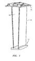
- As shown in FIGS. 1 and 2, an outlet
guide vane assembly 10 used in gas turbine engines has aninner composite base 12 and anouter composite base 14 that positionscomposite vane airfoils 16 during service. The assembly is bolted to the inner diameter of a cylindrical metal case (not shown) by three bolts extending thru the case and the outer base. The inner base is bonded to the vane airfoil and is inseparable without destroying the inner base. The outer base to vane end interface is a bonded assembly which incorporates mechanical retention where thevane end 18 is flared and thevane cavity 20 in theouter base 14 pinches. The vane airfoil is both bonded to and mechanically retained by the outer base. The result is that thevane 22 cannot fall through thebase 14 without material rupture of the base and/or vane. The metallic case (not shown) prevents movement of the flaredvane end 18 in the outboard direction. - The mechanical retention feature prevents installation of replacement outer base detail without complete removal and replacement of the
inner base 12 because neither the inner base,
nor the flaredvane end 18 can fit through the pinchedvane cavity 20. - The outer base is the feature most prone to impact and flexural damage as a result of fan blade centrifuged objects and fan case flexure. Accordingly, there is a need for an economic method for replacing damaged outer bases.
- In accordance with one aspect of the present invention, there is provided an economic method for repairing or replacing a mechanically retained vane. The method broadly comprises the steps of forming a cavity in an outer base oversized sufficiently to insert a flared end of a vane radially outward through the outer base oversized cavity and installing a curved variable pitch wedge having a first constant pitch surface and a second variable pitch surface between the outer base and the flared vane end to secure the flared vane end in position.
- Further, in accordance with a preferred embodiment of the present invention, there is provided a turbine engine component comprising an outer base structure, a cavity within the outer base, at least one airfoil surface having an end positioned within the cavity, and means positioned within the cavity for mechanically retaining the end of the at least one airfoil surface within the cavity, which retention means comprises a wedge having a first constant pitch surface contacting a wall of said cavity and a second variable pitch surface abutting said end.
- Other details of the curved variable pitch wedge retention in a vane outer base are set forth in the following detailed description and the accompanying drawings wherein like reference numerals depict like elements.
-
- FIG. 1 is a perspective view of an outlet guide vane assembly used in a gas turbine engine;
- FIG. 2 is a sectional view of a prior art mechanical retention system for positioning airfoil surfaces of a vane used in the outlet guide vane of FIG. 1;
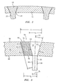
- FIG. 3 is a sectional view of a mechanical retention system for positioning airfoil surfaces of a vane used in the outlet guide vane of FIG. 1 in accordance with the present invention.
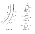
- FIG. 4 illustrates a curved variable pitch wedge;
- FIG. 5 is a sectional view taken along lines 5-5 in FIG. 4;
- FIG. 6 is a sectional view taken along lines 6-6 of FIG. 4;
- FIG. 7 is a sectional view taken along lines 7-7 of FIG. 4;
- FIG. 8 illustrates an outer base for a turbine engine component;
- FIG. 9 is a sectional view taken along lines 9-9 of FIG. 8; and
- FIG. 10 is a sectional view taken along lines 10-10 of FIG. 8.
- Referring now to FIG. 3, there is shown a mechanical retention system for positioning airfoil surfaces of a vane in a turbine engine component, such as an outlet guide vane assembly.
- The mechanical retention system comprises an
oversized pinch cavity 50 machined or molded into anouter base 52 of aturbine engine component 10, such as the outer composite base of an outlet guide vane. Thecavity 50 hascurved side walls side walls outboard edge 58 of theouter base 52 to theinboard edge 60 of theouter base 52. Thecavity 50 is sized so that aflared end 18 of avane airfoil 22 may be installed through the narrow end of thecavity 50 in a radially outward direction. - The flared
vane end 18 hascurved surfaces 53 and 55. Each of thesurfaces 53 and 55 forms a variable pitch angle α relative to thevane stacking line 51. Mechanical retention in the radially inward direction may be maintained by a case wall (not shown). - The flared
end 18 of thevane 22 is located within theoversized cavity 50 so as to position theairfoil surfaces vane airfoil 22. Thevane end 18 is flared so as to have a first cross-sectional dimension d1 adjacent theoutboard edge 58 and a second cross-sectional dimension d2 adjacent theinboard edge 60. The second dimension d2 is less than the first dimension d1. There is a thickness transition between the outboard andinboard edges oversized cavity 50 is provided with a dimension D1 adjacent theouter edge 58 and with a dimension D2 adjacent theinner edge 60. D1 is greater than both D2 and d1. D2 is greater than d2. As a result, there is aspace 66 between aside wall cavity 50 and aside wall 53 or 55 of the flaredend 18. - The flared
vane end 18 may be inserted through the inboard opening of the cavity (Dimension D2). In order to retain theend 18 in place, awedge detail 70 is inserted into thespace 66. Thewedge detail 70 is installed from the large end of thecavity 50. Thewedge detail 70 is contoured to occupy thespace 66 which is the difference between the oversize of thecavity 50 and the flaredvane end 18. - As shown in FIGS. 4-7, the
wedge detail 70 has twoside walls outer end 76 to theinner end 78. In a preferred embodiment of the present invention, theside wall 72 has a constant angle or pitch β with respect to thevane stacking line 51, while theside wall 74 is a variable pitch surface for contacting thesurface 53 of the flaredinner end 18. The constant pitch angle of theside wall 72 helps to simplify geometry of theouter base 52 and further minimize slot circumferential width. The dovetail angle or the pitch of theside wall 74 varies from the leading edge to the trailing edge of thewedge detail 70 with respect to thevane stacking line 51, complicating the wedge geometry. The variablepitch surface wall 74 is designed to match the existing pitch of thesurface 53. In this way, a good bonding surface can be created. It should be appreciated that a space for bonding material may be required betweensurfaces surfaces - The
wedge detail 70 may be formed from any suitable material known in the art, but in a preferred embodiment, it is fabricated from the same material as the outer base. For example, thewedge detail 70 may be formed from a non-metallic material such as polyurethane; a high performance, glass or carbon fiber reinforced engineering composite molding compound such as the material sold under the trade name LYTEX; nylon; or a polyetherimide such as the material sold under the trade name ULTEM. - At a minimum, the
side wall 74 is preferably curved to match the curvature of the flaredvane end 18. Typically, bothside walls vane end 18. - In a preferred embodiment of the present invention, the
outer base 52, thewedge detail 70, and thevane end 18 are both mechanically and adhesively secured. Any adhesive compatible with the base, vane and wedge materials known in the art may be used to adhesively secure these elements together. For example, a two part epoxy plastic adhesive such as Hysol EA9394 or EA9394/C-2 paste adhesive manufactured by Loctite Aerospace of Bay Point, California. Theouter base 52 is preferably formed from an epoxy resim composite material such as LYTEX or an epoxy fiberglass sheet molding compound. For example, a two part epoxy plastic adhesive such as Hysol EA9394 or EA9394/C-2 paste adhesive manufactured by Loctite Aerospace of Bay Point, California. Theouter base 52 is preferably formed from an epoxy resin composite material such as LYTEX or an epoxy fiberglass sheet molding compound. - In order to repair or replace an outer base in a turbine engine component, the
oversized cavity 50 is first machined or formed in anouter base 52 of theturbine engine component 10. The flaredend 18 of avane 22 is then positioned within theoversized cavity 50. An adhesive material in a suitable form may be applied to the walls of the flaredend 18 of the vane and to thewalls walls wedge detail 70. Thereafter, thewedge detail 70 is installed from the large end of thecavity 50. As a result, the mechanical retention that was present in the originalturbine engine component 10 is restored. Either theouter base 52, thevane end 18, or thewedge detail 70 must rupture for thevane end 18 to be pulled through thebase 52. - FIG. 8 illustrates an
outer base 52 having enlargedcavities 50. Eachcavity 50 has a leading (forward) edge 80 and a trailing (aft)edge 82. At the leading (forward) and trailing (aft) edges 80 and 82, the enlarged cavity may have additional base material (thickness) 84 or a secondary reinforcingphase 86 such as continuous fiber for reinforcement and/or for minimizing the circumferential width of the cavity. - One of the advantages of the present invention is that the mechanical retention is maintained, but complete disassembly of the vane and inner bases is not required. This allows for reduced tooling and inspection requirements without degradation of technical merit. Additionally, for vane assemblies with more than one vane airfoil, the relative positioning of vanes is maintained by the inner base simplifying the assembly process and reducing the opportunity for incorrect positioning of the vanes in the finished assembly.
- While the retention system of the present invention has been described as being used in connection with the positioning of airfoil surfaces of vanes in an outlet guide vane, it should be recognized that the retention system could be used in other turbine engine components to position surfaces of blades, vanes, and other radial elements.
- It is apparent that there has been described herein a curved variable pitch wedge retention in vane outer base which fully satisfies the objects, means, and advantages set forth hereinbefore. While the present invention has been described in the context of specific embodiments thereof, other unforeseeable alternatives, modifications, and variations may become apparent to those skilled in the art having read the foregoing description. Accordingly, it is intended to embrace those alternatives, modifications, and variations as fall within the broad scope of the appended claims.
Claims (19)
- A method for repairing or replacing a mechanically retained vane comprises the steps of forming a cavity (50) in an outer base (52) oversized sufficiently to insert a flared end (18) of a vane radially outward in said outer base oversized cavity (50), and installing a curved variable pitch wedge (70) having a first constant pitch surface (72) and a second variable pitch surface (74) between the outer base (52) and the flared vane end (18) to secure the flared vane end (18) in position.
- The method according to claim 1, wherein said forming step comprises forming a cavity (50) having a larger dimension (D1) adjacent an outer edge (58) of said outer base (52) and a smaller dimension (D2) adjacent an inner edge (60) of said outer base (52).
- The method according to claim 2, wherein said installing step comprises installing said curved variable pitch wedge (70) between a wall (54) of said cavity (50) and a wall (53) of said flared end (18) of said vane and installing said wedge (70) so that said constant pitch surface (72) abuts said cavity wall (54) and so that said variable pitch surface (74) abuts a wall (53) of said flared end (18) of said vane.
- The method according to claim 3, wherein said installing step comprises installing said wedge (70) into an end of said cavity (50) having said larger dimension (D1).
- The method of any preceding claim, further comprising applying an adhesive to walls (54,56) of said cavity (50), walls (53,55) of said flared end (18), and said wedge surfaces (72,74) so as to secure said flared end (18) of said vane and said wedge (70) to said side walls of said cavity (50) and said outer base (52).
- The method according to claim 5, wherein said adhesive applying step comprises a two part epoxy paste adhesive.
- A turbine engine component comprising an outer base (52), a cavity (50) within said outer base (52), an airfoil surface having a flared end (18) positioned within said cavity (52), and means positioned within said cavity for mechanically retaining said end (18) of said at least one airfoil surface within said cavity (50), said mechanical retaining means comprising a wedge (70) having a first surface (72) with a constant pitch angle and a second surface (74) having a variable pitch angle.
- The turbine engine component of claim 7, wherein said outer base (52) has an outer edge (58) and an inner edge (60) and said cavity (50) has a larger dimension (D1) adjacent said outer edge (58) and a smaller dimension (D2) adjacent said inner edge (60) and said cavity (50) being larger than said flared end (18).
- The turbine engine component of claim 7, wherein said wedge (70) is positioned between a side wall (54) of said cavity (50) and a wall (74) of said flared end (18).
- The turbine engine component of claim 9, wherein said airfoil surface, said wedge (70) and said outer base (52) are each formed from a non-metallic material.
- The turbine engine component of claim 10, wherein said wedge (70) is formed from a non-metallic material selected from the group consisting of polyurethane, a high performance, glass or carbon fiber reinforced engineering composite molding compound, nylon, and a polyetherimide material.
- The turbine engine component of any of claims 9 to 11, further comprising an adhesive material for joining said wedge (70) to said flared end (18), for joining said flared end (18) to said outer base (52), and for joining said wedge (70) to said outer base (52).
- The turbine engine component of claim 12, wherein said adhesive is a two part epoxy paste adhesive and said outer base (52) is formed from an epoxy resin composite material.
- The turbine engine component according to any of claims 7 to 13, wherein said component comprises an outlet guide vane.
- The turbine engine component according any of to claims 7 to 13, wherein said outer base (52) comprises an outer base of an outlet guide vane, said outlet guide vane has an inner base (12), and said vane extends between said inner base (12) and said outer base (52).
- The turbine engine component of any of claims 7 to 15, wherein said flared end (18) of said airfoil surface has two sides with a variable dovetail angle (α) with respect to an airfoil stacking line (51).
- The turbine engine component of any of claims 7 to 15, wherein said flared end (18) has a surface (74) with a variable dovetail angle (α) and wherein said variable pitch angle surface (74) of said wedge (70) abuts said surface having a variable dovetail angle.
- The turbine engine component of any of claims 7 to 17, further comprising said cavity (50) having a forward end (80) and an aft end (82), with structural reinforcement material at said forward and aft ends (80,82).
- The turbine engine component of any of claims 7 to 18, further comprising said cavity (50) having a forward end (80) and an aft end (82) and means for minimizing the circumferential width of the cavity at said forward and aft ends (80,82).
Applications Claiming Priority (1)
| Application Number | Priority Date | Filing Date | Title |
|---|---|---|---|
| US11/519,637 US7665963B2 (en) | 2006-09-06 | 2006-09-12 | Curved variable pitch wedge retention in vane outer base |
Publications (3)
| Publication Number | Publication Date |
|---|---|
| EP1905959A2 true EP1905959A2 (en) | 2008-04-02 |
| EP1905959A3 EP1905959A3 (en) | 2008-06-04 |
| EP1905959B1 EP1905959B1 (en) | 2010-03-31 |
Family
ID=38828731
Family Applications (1)
| Application Number | Title | Priority Date | Filing Date |
|---|---|---|---|
| EP07253600A Ceased EP1905959B1 (en) | 2006-09-12 | 2007-09-11 | Variable pitch wedge retention in vane outer base |
Country Status (5)
| Country | Link |
|---|---|
| US (1) | US7665963B2 (en) |
| EP (1) | EP1905959B1 (en) |
| JP (1) | JP2008069775A (en) |
| DE (1) | DE602007005567D1 (en) |
| SG (1) | SG141321A1 (en) |
Cited By (2)
| Publication number | Priority date | Publication date | Assignee | Title |
|---|---|---|---|---|
| EP2159371A2 (en) | 2008-08-28 | 2010-03-03 | United Technologies Corporation | Gas turbine airfoil assemblies and methods of repair |
| EP2787179A1 (en) * | 2013-04-05 | 2014-10-08 | Rolls-Royce plc | Vane assembly, corresponding manufacturing method and gas turbine engine fan assembly |
Families Citing this family (12)
| Publication number | Priority date | Publication date | Assignee | Title |
|---|---|---|---|---|
| US8967977B2 (en) | 2010-08-30 | 2015-03-03 | United Technologies Corporation | Locked spacer for a gas turbine engine shaft |
| GB201015862D0 (en) * | 2010-09-22 | 2010-10-27 | Rolls Royce Plc | A damped assembly |
| US9610644B2 (en) * | 2011-02-08 | 2017-04-04 | United Technologies Corporation | Mate face brazing for turbine components |
| US9541540B2 (en) | 2012-10-04 | 2017-01-10 | United Technologies Corporation | Non-destructive test inspection method for evaluating thermal degradation of bismaleimide resin |
| CA2903738A1 (en) * | 2013-03-07 | 2014-09-12 | Rolls-Royce Canada, Ltd. | Gas turbine engine comprising an outboard insertion system of vanes and corresponding assembling method |
| US9840929B2 (en) * | 2013-05-28 | 2017-12-12 | Pratt & Whitney Canada Corp. | Gas turbine engine vane assembly and method of mounting same |
| US20160298465A1 (en) | 2013-12-12 | 2016-10-13 | United Technologies Corporation | Gas turbine engine component cooling passage with asymmetrical pedestals |
| US9567871B2 (en) | 2014-04-23 | 2017-02-14 | Sikorsky Aircraft Corporation | Impeller retention apparatus |
| US20190234222A1 (en) * | 2018-01-30 | 2019-08-01 | United Technologies Corporation | Angled vane slot |
| US11268394B2 (en) * | 2020-03-13 | 2022-03-08 | General Electric Company | Nozzle assembly with alternating inserted vanes for a turbine engine |
| US12275532B2 (en) | 2022-08-15 | 2025-04-15 | General Electric Company | Gas turbine engine noise reduction |
| US12352181B2 (en) | 2023-01-30 | 2025-07-08 | General Electric Company | Turbine airfoils |
Citations (2)
| Publication number | Priority date | Publication date | Assignee | Title |
|---|---|---|---|---|
| US5074752A (en) | 1990-08-06 | 1991-12-24 | General Electric Company | Gas turbine outlet guide vane mounting assembly |
| US5569019A (en) | 1993-12-22 | 1996-10-29 | Alliedsignal Inc. | Tear-away composite fan stator vane |
Family Cites Families (10)
| Publication number | Priority date | Publication date | Assignee | Title |
|---|---|---|---|---|
| US2834537A (en) * | 1954-01-18 | 1958-05-13 | Ryan Aeronautical Co | Compressor stator structure |
| US2857093A (en) * | 1954-12-02 | 1958-10-21 | Cincinnati Testing & Res Lab | Stator casing and blade assembly |
| US3339833A (en) * | 1963-12-04 | 1967-09-05 | Rolls Royce | Axial fluid flow machine such as a compressor or turbine |
| US3778185A (en) * | 1972-08-28 | 1973-12-11 | United Aircraft Corp | Composite strut joint construction |
| FR2568953B1 (en) * | 1984-08-08 | 1989-02-10 | Ratier Figeac Soc | FIXED BLADE FOR REACTORS |
| US4907946A (en) * | 1988-08-10 | 1990-03-13 | General Electric Company | Resiliently mounted outlet guide vane |
| FR2654463A1 (en) * | 1989-11-15 | 1991-05-17 | Snecma | TURBOMACHINE STATOR ELEMENT. |
| US6619917B2 (en) * | 2000-12-19 | 2003-09-16 | United Technologies Corporation | Machined fan exit guide vane attachment pockets for use in a gas turbine |
| US7637718B2 (en) * | 2005-09-12 | 2009-12-29 | Pratt & Whitney Canada Corp. | Vane assembly with outer grommets |
| US7510372B2 (en) * | 2006-04-19 | 2009-03-31 | United Technologies Corporation | Wedge repair of mechanically retained vanes |
-
2006
- 2006-09-12 US US11/519,637 patent/US7665963B2/en not_active Expired - Fee Related
-
2007
- 2007-08-21 SG SG200706123-7A patent/SG141321A1/en unknown
- 2007-09-06 JP JP2007230898A patent/JP2008069775A/en active Pending
- 2007-09-11 EP EP07253600A patent/EP1905959B1/en not_active Ceased
- 2007-09-11 DE DE602007005567T patent/DE602007005567D1/en active Active
Patent Citations (2)
| Publication number | Priority date | Publication date | Assignee | Title |
|---|---|---|---|---|
| US5074752A (en) | 1990-08-06 | 1991-12-24 | General Electric Company | Gas turbine outlet guide vane mounting assembly |
| US5569019A (en) | 1993-12-22 | 1996-10-29 | Alliedsignal Inc. | Tear-away composite fan stator vane |
Cited By (5)
| Publication number | Priority date | Publication date | Assignee | Title |
|---|---|---|---|---|
| EP2159371A2 (en) | 2008-08-28 | 2010-03-03 | United Technologies Corporation | Gas turbine airfoil assemblies and methods of repair |
| EP2159371A3 (en) * | 2008-08-28 | 2013-05-29 | United Technologies Corporation | Gas turbine airfoil assemblies and methods of repair |
| EP2159371B1 (en) | 2008-08-28 | 2016-12-14 | United Technologies Corporation | Gas turbine airfoil assemblies and methods of repair |
| EP2787179A1 (en) * | 2013-04-05 | 2014-10-08 | Rolls-Royce plc | Vane assembly, corresponding manufacturing method and gas turbine engine fan assembly |
| US9593586B2 (en) | 2013-04-05 | 2017-03-14 | Rolls-Royce Plc | Vane assembly and method of making the same |
Also Published As
| Publication number | Publication date |
|---|---|
| JP2008069775A (en) | 2008-03-27 |
| US20080063521A1 (en) | 2008-03-13 |
| SG141321A1 (en) | 2008-04-28 |
| DE602007005567D1 (en) | 2010-05-12 |
| EP1905959A3 (en) | 2008-06-04 |
| US7665963B2 (en) | 2010-02-23 |
| EP1905959B1 (en) | 2010-03-31 |
Similar Documents
| Publication | Publication Date | Title |
|---|---|---|
| EP1905959B1 (en) | Variable pitch wedge retention in vane outer base | |
| EP1847681B1 (en) | Wedge repair of mechanically retained vanes | |
| EP1983160B1 (en) | Gas turbine engine vane | |
| US8246310B2 (en) | Turbomachine fan | |
| US7334997B2 (en) | Hybrid blisk | |
| US5083426A (en) | Integrated engine shroud for gas turbine engines | |
| EP2243953A2 (en) | Turbine blade fabrication | |
| EP2503102A2 (en) | A rotor having an annulus filler | |
| EP1911931A2 (en) | Fan exit guide vane and method of repairing therof | |
| US9523281B2 (en) | Blade for a wind turbine | |
| EP2713014A2 (en) | Annulus filler for axial flow machine | |
| EP4168654B1 (en) | Turbomachine blade having a metallic leading edge | |
| CN110725721B (en) | Composite outlet guide vane with metal fasteners for a turbomachine | |
| CN108691810B (en) | Turbine engine containment assembly and method of manufacture | |
| US10724390B2 (en) | Collar support assembly for airfoils | |
| CN115989179A (en) | Unducted propeller with variable pitch blades including a turbulence-reducing platform | |
| US10662974B2 (en) | Turbine engine flow guide vane with removable attachment | |
| CN115413305B (en) | Blade made of composite material comprising a metal reinforcement and method for manufacturing such a blade | |
| US12158081B2 (en) | Fairing element for surrounding an obstacle in a fluid flow | |
| EP3323998A1 (en) | Inner shroud segment and corresponding inner shroud and gas turbine motor | |
| EP4365077A1 (en) | Airfoil and methods of assembly thereof | |
| CN121866394A (en) | Low-pressure compressor housing for aircraft turbine engines | |
| CN112969842B (en) | Air flow straightener unit comprising a centering and attachment plate | |
| CN122055522A (en) | Housing for a low-pressure compressor of an aircraft turbine engine | |
| CN117355663A (en) | Platform for fan assembly |
Legal Events
| Date | Code | Title | Description |
|---|---|---|---|
| PUAI | Public reference made under article 153(3) epc to a published international application that has entered the european phase |
Free format text: ORIGINAL CODE: 0009012 |
|
| AK | Designated contracting states |
Kind code of ref document: A2 Designated state(s): AT BE BG CH CY CZ DE DK EE ES FI FR GB GR HU IE IS IT LI LT LU LV MC MT NL PL PT RO SE SI SK TR |
|
| AX | Request for extension of the european patent |
Extension state: AL BA HR MK YU |
|
| PUAL | Search report despatched |
Free format text: ORIGINAL CODE: 0009013 |
|
| AK | Designated contracting states |
Kind code of ref document: A3 Designated state(s): AT BE BG CH CY CZ DE DK EE ES FI FR GB GR HU IE IS IT LI LT LU LV MC MT NL PL PT RO SE SI SK TR |
|
| AX | Request for extension of the european patent |
Extension state: AL BA HR MK RS |
|
| RIC1 | Information provided on ipc code assigned before grant |
Ipc: F01D 9/04 20060101ALI20080430BHEP Ipc: F01D 5/00 20060101AFI20080430BHEP |
|
| 17P | Request for examination filed |
Effective date: 20081024 |
|
| 17Q | First examination report despatched |
Effective date: 20081121 |
|
| AKX | Designation fees paid |
Designated state(s): DE GB |
|
| GRAP | Despatch of communication of intention to grant a patent |
Free format text: ORIGINAL CODE: EPIDOSNIGR1 |
|
| GRAC | Information related to communication of intention to grant a patent modified |
Free format text: ORIGINAL CODE: EPIDOSCIGR1 |
|
| RIN1 | Information on inventor provided before grant (corrected) |
Inventor name: BOGUE, WILLIAM Inventor name: MCCOLLUM, BRUCE A. |
|
| GRAS | Grant fee paid |
Free format text: ORIGINAL CODE: EPIDOSNIGR3 |
|
| GRAA | (expected) grant |
Free format text: ORIGINAL CODE: 0009210 |
|
| AK | Designated contracting states |
Kind code of ref document: B1 Designated state(s): DE GB |
|
| REG | Reference to a national code |
Ref country code: GB Ref legal event code: FG4D |
|
| REF | Corresponds to: |
Ref document number: 602007005567 Country of ref document: DE Date of ref document: 20100512 Kind code of ref document: P |
|
| PLBE | No opposition filed within time limit |
Free format text: ORIGINAL CODE: 0009261 |
|
| STAA | Information on the status of an ep patent application or granted ep patent |
Free format text: STATUS: NO OPPOSITION FILED WITHIN TIME LIMIT |
|
| 26N | No opposition filed |
Effective date: 20110104 |
|
| REG | Reference to a national code |
Ref country code: DE Ref legal event code: R082 Ref document number: 602007005567 Country of ref document: DE Representative=s name: SCHMITT-NILSON SCHRAUD WAIBEL WOHLFROM PATENTA, DE |
|
| REG | Reference to a national code |
Ref country code: DE Ref legal event code: R082 Ref document number: 602007005567 Country of ref document: DE Representative=s name: SCHMITT-NILSON SCHRAUD WAIBEL WOHLFROM PATENTA, DE Ref country code: DE Ref legal event code: R081 Ref document number: 602007005567 Country of ref document: DE Owner name: UNITED TECHNOLOGIES CORP. (N.D.GES.D. STAATES , US Free format text: FORMER OWNER: UNITED TECHNOLOGIES CORPORATION, HARTFORD, CONN., US |
|
| PGFP | Annual fee paid to national office [announced via postgrant information from national office to epo] |
Ref country code: GB Payment date: 20210820 Year of fee payment: 15 Ref country code: DE Payment date: 20210818 Year of fee payment: 15 |
|
| REG | Reference to a national code |
Ref country code: DE Ref legal event code: R081 Ref document number: 602007005567 Country of ref document: DE Owner name: RAYTHEON TECHNOLOGIES CORPORATION (N.D.GES.D.S, US Free format text: FORMER OWNER: UNITED TECHNOLOGIES CORP. (N.D.GES.D. STAATES DELAWARE), FARMINGTON, CONN., US |
|
| REG | Reference to a national code |
Ref country code: DE Ref legal event code: R119 Ref document number: 602007005567 Country of ref document: DE |
|
| GBPC | Gb: european patent ceased through non-payment of renewal fee |
Effective date: 20220911 |
|
| PG25 | Lapsed in a contracting state [announced via postgrant information from national office to epo] |
Ref country code: DE Free format text: LAPSE BECAUSE OF NON-PAYMENT OF DUE FEES Effective date: 20230401 |
|
| PG25 | Lapsed in a contracting state [announced via postgrant information from national office to epo] |
Ref country code: GB Free format text: LAPSE BECAUSE OF NON-PAYMENT OF DUE FEES Effective date: 20220911 |