EP1905860A2 - Porous abradable coating and method for applying the same. - Google Patents
Porous abradable coating and method for applying the same. Download PDFInfo
- Publication number
- EP1905860A2 EP1905860A2 EP07117320A EP07117320A EP1905860A2 EP 1905860 A2 EP1905860 A2 EP 1905860A2 EP 07117320 A EP07117320 A EP 07117320A EP 07117320 A EP07117320 A EP 07117320A EP 1905860 A2 EP1905860 A2 EP 1905860A2
- Authority
- EP
- European Patent Office
- Prior art keywords
- abradable
- layer
- powder
- patterned
- applying
- Prior art date
- Legal status (The legal status is an assumption and is not a legal conclusion. Google has not performed a legal analysis and makes no representation as to the accuracy of the status listed.)
- Withdrawn
Links
Images


Classifications
-
- C—CHEMISTRY; METALLURGY
- C23—COATING METALLIC MATERIAL; COATING MATERIAL WITH METALLIC MATERIAL; CHEMICAL SURFACE TREATMENT; DIFFUSION TREATMENT OF METALLIC MATERIAL; COATING BY VACUUM EVAPORATION, BY SPUTTERING, BY ION IMPLANTATION OR BY CHEMICAL VAPOUR DEPOSITION, IN GENERAL; INHIBITING CORROSION OF METALLIC MATERIAL OR INCRUSTATION IN GENERAL
- C23C—COATING METALLIC MATERIAL; COATING MATERIAL WITH METALLIC MATERIAL; SURFACE TREATMENT OF METALLIC MATERIAL BY DIFFUSION INTO THE SURFACE, BY CHEMICAL CONVERSION OR SUBSTITUTION; COATING BY VACUUM EVAPORATION, BY SPUTTERING, BY ION IMPLANTATION OR BY CHEMICAL VAPOUR DEPOSITION, IN GENERAL
- C23C4/00—Coating by spraying the coating material in the molten state, e.g. by flame, plasma or electric discharge
- C23C4/02—Pretreatment of the material to be coated, e.g. for coating on selected surface areas
-
- C—CHEMISTRY; METALLURGY
- C23—COATING METALLIC MATERIAL; COATING MATERIAL WITH METALLIC MATERIAL; CHEMICAL SURFACE TREATMENT; DIFFUSION TREATMENT OF METALLIC MATERIAL; COATING BY VACUUM EVAPORATION, BY SPUTTERING, BY ION IMPLANTATION OR BY CHEMICAL VAPOUR DEPOSITION, IN GENERAL; INHIBITING CORROSION OF METALLIC MATERIAL OR INCRUSTATION IN GENERAL
- C23C—COATING METALLIC MATERIAL; COATING MATERIAL WITH METALLIC MATERIAL; SURFACE TREATMENT OF METALLIC MATERIAL BY DIFFUSION INTO THE SURFACE, BY CHEMICAL CONVERSION OR SUBSTITUTION; COATING BY VACUUM EVAPORATION, BY SPUTTERING, BY ION IMPLANTATION OR BY CHEMICAL VAPOUR DEPOSITION, IN GENERAL
- C23C4/00—Coating by spraying the coating material in the molten state, e.g. by flame, plasma or electric discharge
-
- C—CHEMISTRY; METALLURGY
- C23—COATING METALLIC MATERIAL; COATING MATERIAL WITH METALLIC MATERIAL; CHEMICAL SURFACE TREATMENT; DIFFUSION TREATMENT OF METALLIC MATERIAL; COATING BY VACUUM EVAPORATION, BY SPUTTERING, BY ION IMPLANTATION OR BY CHEMICAL VAPOUR DEPOSITION, IN GENERAL; INHIBITING CORROSION OF METALLIC MATERIAL OR INCRUSTATION IN GENERAL
- C23C—COATING METALLIC MATERIAL; COATING MATERIAL WITH METALLIC MATERIAL; SURFACE TREATMENT OF METALLIC MATERIAL BY DIFFUSION INTO THE SURFACE, BY CHEMICAL CONVERSION OR SUBSTITUTION; COATING BY VACUUM EVAPORATION, BY SPUTTERING, BY ION IMPLANTATION OR BY CHEMICAL VAPOUR DEPOSITION, IN GENERAL
- C23C4/00—Coating by spraying the coating material in the molten state, e.g. by flame, plasma or electric discharge
- C23C4/01—Selective coating, e.g. pattern coating, without pre-treatment of the material to be coated
Definitions
- the disclosure relates generally to abradable coatings, and more specifically to porous abradable coatings applied to a substrate.
- Abradable type coatings have been applied to the turbine shroud to help establish a minimum, i.e., optimum, running clearance between the shroud and bucket tips under steady-state temperature conditions.
- coatings have been applied to the surface of the shroud facing the buckets using a material that can be readily abraded by the tips of the buckets as they turn inside the shroud at high speed with little or no damage to the bucket tips. Initially, a clearance exists between the bucket tips and the coating when the gas turbine is stopped and the components are at ambient temperature.
- abradable coatings are effective clearance minimizers, a coating that, as a whole, could better withstand local rubs (i.e. withstand a local rub on the coating without wholesale or large area delamination of the coating) would be desirable. This can be achieved via increased coating porosity.
- coating porosity is achieved by including a polymeric component in the coating, the polymeric component being burned out after coating application, leaving behind a porosity. A more efficient and effective means of creating porosity in a abradable coating is desirable.
- a porous abradable coating including at least one abradable layer applicable to a substrate, said at least one abradable layer comprising coarsely cut powder pieces.
- Also disclosed is a method for applying a porous abradable coating including selecting a coarsely cut abradable powder comprising coarsely cut powder pieces, applying at least one abradable layer comprising the coarsely cut abradable powder to a substrate, and creating a porosity in the at least one layer via the coarsely cut abradable powder.
- a method for applying a porous abradable coating including selecting a coarsely cut abradable powder comprising coarsely cut powder pieces, applying an adhesion abradable layer comprising the coarsely cut powder to a substrate, applying a patterned abradable layer including the coarsely cut abradable powder to the adhesion abradable layer, adhering the patterned abradable layer to the adhesion abradable layer, the adhering being promoted via a roughness of the coarsely cut abradable powder, and creating a porosity in the adhesion layer and the patterned layer via the coarsely cut abradable powder pieces.
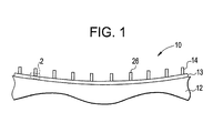
- a porous abradable coating 10 is illustrated.
- the coating 10 is applied to a substrate 12, such as an environmental barrier coated (EBC) turbine shroud, in at least one layer.
- the coating 10 is applied in an adhesion abradable layer 13 and a patterned abradable layer 14.
- a method for applying the coating 10 will be discussed hereinbelow, beginning with selection of the powder 15 (as shown in Figure 2) comprising the coating 10.
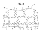
- the powder 15 is selected to include relatively large, coarse cut pieces 16.
- the selection process involves a sifting of the abradable powder 15 through a screen that includes square openings approximately 90 microns across. The powder 15 that passes through these openings is then sifted through a screen that includes square openings approximately 44 microns across. The powder 15 that passes through these openings is then discarded, and the powder 15 that cannot pass is selected. Thus, pieces 16 with an approximate diameter between 44 and 90 microns are used.
- other more conventional powders 15 use a finer powder that includes pieces as small as 8 (ceramic) and 16 (metal) microns.
- the largeness and coarseness of the pieces 16 allows the powder 15 applied in the layers 14 and 13 to include relatively large open voids 18.
- these voids 18 allow for a relatively large coating porosity 20 of at least 8 percent volume (with an exemplary range of 8-12%), even after a heat treatment that will be discussed later in the disclosure.
- the coarseness of the pieces 16 produce a degree of roughness 22 in the adhesion layer 13 that promotes adhesion to the patterned layer 14.
- the powder 15 includes a ceramic composition, which may specifically comprise yttria stabilized zirconia, barium strontium aluminosilicate, and a composition including .75 mole BaO, .25 mole SrO, 1 mole Al203, and 2 moles Si02.
- the coating 10 may be applied.
- the adhesion layer 13 (partially applied in the Figure) is applied or "flash-coated" to the substrate 12 via a thermal spray process, such as air plasma spray 24 or physical vapor deposition (PVD).
- parameter of the air plasma spray is calibrated and optimized for coarse particles that include sizes selected to collectively produce the desired level of porosity.
- the patterned layer 14 is applied to the adhesion layer 13, with a pattern of ridges 26 being formed in the patterned layer 14 (partially applied in the Figure) by, in an exemplary embodiment, successive passes of plasma sprayed powder 15 over a pattern mask 28, with parameter of the air plasma spray again being optimized for coarse particles that include sizes selected to collectively produce the desired level of porosity. As mentioned above, adherence of patterned layer 14 is promoted and strengthened via the roughness 22 of the adhesion layer 13.
- the layers 13 and 14 are heat-treated.
- this heat treatment is accomplished via an air furnace, though a plasma torch may also be used.
- the heat is applied at a temperature sufficient enough to partially melt the pieces 16, so as to mechanically and chemically bond each piece 16 to an adjacent piece 16 (and in so doing, strengthen the bond between the layers 13 and 14), aiding in erosion resistance during turbine operation.
- the temperature is not so great however (between 1250 and 1300 degrees C), as to completely melt the pieces 16 and decrease porosity by causing the voids 18 to fill with the melting pieces 16.
- the combination of moderate heat treatment and particle sizing maintain an incomplete melting, which further maintains the voids 18 between the only semi-molten pieces 16. As nothing has to be completely burned out of the coating 10 to create the desired porosity 20, the integrity of the pieces 16 is substantially preserved, and thus, the desired porosity 20 is efficiently and effectively created.
Landscapes
- Chemical & Material Sciences (AREA)
- Engineering & Computer Science (AREA)
- Mechanical Engineering (AREA)
- Plasma & Fusion (AREA)
- Chemical Kinetics & Catalysis (AREA)
- Materials Engineering (AREA)
- Physics & Mathematics (AREA)
- Metallurgy (AREA)
- Organic Chemistry (AREA)
- Coating By Spraying Or Casting (AREA)
- Turbine Rotor Nozzle Sealing (AREA)
- Materials For Medical Uses (AREA)
- Application Of Or Painting With Fluid Materials (AREA)
Abstract
Description
- The disclosure relates generally to abradable coatings, and more specifically to porous abradable coatings applied to a substrate.
- In a gas turbine engine, in order to achieve maximum engine efficiency (and corresponding maximum electrical power generation), it is important that the buckets rotate within the turbine casing or "shroud" with minimal interference and with the highest possible efficiency relative to the amount of energy available from the expanding working fluid. Typically, highest operation efficiencies can be achieved by maintaining a minimum threshold clearance between the shroud and tips of the bucket. Maintaining a minimum clearance prevents unwanted "leakage" of a hot gas over tip of the buckets, increased clearances lead to leakage problems and cause significant decreases in overall efficiency of the turbine. However, it should be appreciated that if bucket tips rub against a particular location of the shroud such that the bucket tip is eroded, the erosion of the bucket tip increases clearances between bucket tip and shroud in other locations, again resulting in unwanted leakage.
- The need to maintain adequate clearance without significant loss of efficiency is made more difficult by the fact that as the turbine rotates, centrifugal forces acting on the turbine components can cause the buckets to expand in an outward direction toward the shroud, particularly when influenced by the high operating temperatures. Thus, it is important to establish the lowest effective running clearances between the shroud and bucket tips at the maximum anticipated operating temperatures.
- Abradable type coatings have been applied to the turbine shroud to help establish a minimum, i.e., optimum, running clearance between the shroud and bucket tips under steady-state temperature conditions. In particular, coatings have been applied to the surface of the shroud facing the buckets using a material that can be readily abraded by the tips of the buckets as they turn inside the shroud at high speed with little or no damage to the bucket tips. Initially, a clearance exists between the bucket tips and the coating when the gas turbine is stopped and the components are at ambient temperature. Later, during normal operation the clearance decreases due to the centrifugal forces and temperature changes in rotating and stationary components inevitably resulting in at least some radial extension of the bucket tips, causing them to contact the coating on the shroud and wear away a part of the coating to establish the minimum running clearance. With abradable coatings clearances can be reduced with the assurance that if contact occurs, the sacrificial part is the abradable coating instead of the bucket tip.
- Though abradable coatings are effective clearance minimizers, a coating that, as a whole, could better withstand local rubs (i.e. withstand a local rub on the coating without wholesale or large area delamination of the coating) would be desirable. This can be achieved via increased coating porosity. Currently, coating porosity is achieved by including a polymeric component in the coating, the polymeric component being burned out after coating application, leaving behind a porosity. A more efficient and effective means of creating porosity in a abradable coating is desirable.
- Disclosed is a porous abradable coating including at least one abradable layer applicable to a substrate, said at least one abradable layer comprising coarsely cut powder pieces.
- Also disclosed is a method for applying a porous abradable coating, the method including selecting a coarsely cut abradable powder comprising coarsely cut powder pieces, applying at least one abradable layer comprising the coarsely cut abradable powder to a substrate, and creating a porosity in the at least one layer via the coarsely cut abradable powder.
- Further disclosed is a method for applying a porous abradable coating, the method including selecting a coarsely cut abradable powder comprising coarsely cut powder pieces, applying an adhesion abradable layer comprising the coarsely cut powder to a substrate, applying a patterned abradable layer including the coarsely cut abradable powder to the adhesion abradable layer, adhering the patterned abradable layer to the adhesion abradable layer, the adhering being promoted via a roughness of the coarsely cut abradable powder, and creating a porosity in the adhesion layer and the patterned layer via the coarsely cut abradable powder pieces.
- Embodiments of the present invention will now be described, by way of example only, with reference to the drawings wherein like elements are numbered alike in the several FIGURES:
- Figure 1 is a schematic cross-section of a porous abradable coating;
- Figure 2 is a schematic cross-section of
section 2 of figure 1; - Figure 3 is a schematic cross-section of an adhesive layer of the porous abradable coating being applied; and
- Figure 4 is a schematic cross-section of a patterned layer of the porous abradable coating being applied.
- Referring to Figure 1, a porous
abradable coating 10 is illustrated. Thecoating 10 is applied to asubstrate 12, such as an environmental barrier coated (EBC) turbine shroud, in at least one layer. In an exemplary embodiment, thecoating 10 is applied in an adhesionabradable layer 13 and a patternedabradable layer 14. A method for applying thecoating 10 will be discussed hereinbelow, beginning with selection of the powder 15 (as shown in Figure 2) comprising thecoating 10. - Referring to Figure 2, the
powder 15 is selected to include relatively large,coarse cut pieces 16. The selection process involves a sifting of theabradable powder 15 through a screen that includes square openings approximately 90 microns across. Thepowder 15 that passes through these openings is then sifted through a screen that includes square openings approximately 44 microns across. Thepowder 15 that passes through these openings is then discarded, and thepowder 15 that cannot pass is selected. Thus,pieces 16 with an approximate diameter between 44 and 90 microns are used. By comparison, other moreconventional powders 15 use a finer powder that includes pieces as small as 8 (ceramic) and 16 (metal) microns. - The largeness and coarseness of the
pieces 16 allows thepowder 15 applied in thelayers open voids 18. In an exemplary embodiment, thesevoids 18 allow for a relativelylarge coating porosity 20 of at least 8 percent volume (with an exemplary range of 8-12%), even after a heat treatment that will be discussed later in the disclosure. In addition to creating the desiredporosity 20, the coarseness of thepieces 16 produce a degree ofroughness 22 in theadhesion layer 13 that promotes adhesion to the patternedlayer 14. It should be appreciated that in an exemplary embodiment thepowder 15 includes a ceramic composition, which may specifically comprise yttria stabilized zirconia, barium strontium aluminosilicate, and a composition including .75 mole BaO, .25 mole SrO, 1 mole Al203, and 2 moles Si02. - Once the
powder 15 is selected, thecoating 10 may be applied. Referring to Figure 3, in an exemplary embodiment the adhesion layer 13 (partially applied in the Figure) is applied or "flash-coated" to thesubstrate 12 via a thermal spray process, such asair plasma spray 24 or physical vapor deposition (PVD). In an exemplary embodiment, parameter of the air plasma spray is calibrated and optimized for coarse particles that include sizes selected to collectively produce the desired level of porosity. Referring to Figure 4, thepatterned layer 14 is applied to theadhesion layer 13, with a pattern ofridges 26 being formed in the patterned layer 14 (partially applied in the Figure) by, in an exemplary embodiment, successive passes of plasma sprayedpowder 15 over apattern mask 28, with parameter of the air plasma spray again being optimized for coarse particles that include sizes selected to collectively produce the desired level of porosity. As mentioned above, adherence ofpatterned layer 14 is promoted and strengthened via theroughness 22 of theadhesion layer 13. - To further mechanically and chemically strengthen the adhesive bond between the applied
adhesion layer 13 and patternedlayer 14, and thepieces 16 within each layer, thelayers pieces 16, so as to mechanically and chemically bond eachpiece 16 to an adjacent piece 16 (and in so doing, strengthen the bond between thelayers 13 and 14), aiding in erosion resistance during turbine operation. The temperature is not so great however (between 1250 and 1300 degrees C), as to completely melt thepieces 16 and decrease porosity by causing thevoids 18 to fill with themelting pieces 16. Thus, the combination of moderate heat treatment and particle sizing maintain an incomplete melting, which further maintains thevoids 18 between the onlysemi-molten pieces 16. As nothing has to be completely burned out of thecoating 10 to create the desiredporosity 20, the integrity of thepieces 16 is substantially preserved, and thus, the desiredporosity 20 is efficiently and effectively created. - While the invention has been described with reference to an exemplary embodiment, it should be understood by those skilled in the art that various changes may be made and equivalents may be substituted for elements thereof without departing from the scope of the invention. In addition, many modifications may be made to adapt a particular situation or substance to the teachings of the invention without departing from the scope thereof. Therefore, it is important that the invention not be limited to the particular embodiment disclosed as the best mode contemplated for carrying out this invention, but that the invention will include all embodiments falling within the scope of the apportioned claims. Moreover, unless specifically stated any use of the terms first, second, etc. do not denote any order or importance, but rather the terms first, second, etc. are used to distinguish one element from another.
Claims (10)
- A porous abradable coating (10) comprising:at least one abradable layer (13) applicable to a substrate (12), said at least one abradable layer (13) comprising coarsely cut powder pieces (16).
- An abradable coating (10) according to claim 1, wherein said at least one layer includes a ceramic composition, wherein said ceramic composition is at least one of yttria stabilized zirconia, barium strontium aluminosilicate, and a composition including .75 mole BaO, .25 mole SrO, 1 mole Al203, and 2 moles SiO2.
- An abradable coating (10) according to claim 1, wherein at least one layer is an adhesion abradable layer (13) applicable to said substrate (12), and a patterned abradable layer (14) adherable to said adhesion abradable layer (13), said patterned abradable layer (14) defining at least one ridge.
- An abradable coating (10) according to claim 1, wherein said at least one abradable layer (13) includes a porosity (20) of at least 8 percent volume.
- A method for applying a porous abradable coating (10), the method comprising:selecting a coarsely cut abradable powder (15) comprising coarsely cut powder pieces (16);applying at least one abradable layer (13) comprising said coarsely cut abradable powder (15) to a substrate(12); andcreating a porosity (20) in said at least one layer (13) via said coarsely cut abradable powder (15).
- A method for applying a porous abradable coating (10), the method comprising:selecting a coarsely cut abradable powder (15) comprising coarsely cut powder pieces (16);applying an adhesion abradable layer (13) comprising said coarsely cut powder (15) to a substrate (12);applying a patterned abradable layer (14) including said coarsely cut abradable powder (15) to said adhesion abradable layer (13);adhering said patterned abradable layer (14) to said adhesion abradable layer (13), said adhering being promoted via a roughness (22) of said coarsely cut abradable powder(15); andcreating a porosity (20) in said adhesion layer (13) and said patterned layer (14) via said coarsely cut abradable powder pieces (16).
- A method according to claim 6, further including creating an abradable pattern of ridges (26) in said patterned abradable layer (14) via a patterned mask (28).
- A method according to claim 6, wherein said applying said adhesion layer (13) includes applying using a plasma air spray (24), wherein said applying said patterned layer (13) includes applying using successive passes of a plasma air spray (24) over said patterned mask (28).
- A method according to claim 6, further including heat treating said adhesion layer (13) and said patterned layer (14) to allow said adhesion layer (13) and said patterned layer (14) to resist erosion via strengthened adherence, a temperature of said heat treating being selected to retain said desired porosity (20) by incompletely melting said coarsely cut abradable powder pieces (16).
- A method according to claim 6, wherein said selecting includes selecting said coarsely cut powder (15) to include a coarseness that allows said desired porosity (20) to be at least 8 percent volume.
Applications Claiming Priority (1)
| Application Number | Priority Date | Filing Date | Title |
|---|---|---|---|
| US11/537,238 US20080081109A1 (en) | 2006-09-29 | 2006-09-29 | Porous abradable coating and method for applying the same |
Publications (2)
| Publication Number | Publication Date |
|---|---|
| EP1905860A2 true EP1905860A2 (en) | 2008-04-02 |
| EP1905860A3 EP1905860A3 (en) | 2009-04-08 |
Family
ID=38691830
Family Applications (1)
| Application Number | Title | Priority Date | Filing Date |
|---|---|---|---|
| EP07117320A Withdrawn EP1905860A3 (en) | 2006-09-29 | 2007-09-27 | Porous abradable coating and method for applying the same. |
Country Status (4)
| Country | Link |
|---|---|
| US (1) | US20080081109A1 (en) |
| EP (1) | EP1905860A3 (en) |
| JP (1) | JP5219442B2 (en) |
| CN (1) | CN101161733A (en) |
Cited By (4)
| Publication number | Priority date | Publication date | Assignee | Title |
|---|---|---|---|---|
| US10273192B2 (en) | 2015-02-17 | 2019-04-30 | Rolls-Royce Corporation | Patterned abradable coating and methods for the manufacture thereof |
| US11313243B2 (en) | 2018-07-12 | 2022-04-26 | Rolls-Royce North American Technologies, Inc. | Non-continuous abradable coatings |
| US11976569B2 (en) | 2019-11-14 | 2024-05-07 | Rolls-Royce Corporation | Fused filament fabrication of abradable coatings |
| US12459196B2 (en) | 2019-11-14 | 2025-11-04 | Rolls-Royce Corporation | Patterned filament for fused filament fabrication |
Families Citing this family (15)
| Publication number | Priority date | Publication date | Assignee | Title |
|---|---|---|---|---|
| US8047773B2 (en) * | 2007-08-23 | 2011-11-01 | General Electric Company | Gas turbine shroud support apparatus |
| US8046915B2 (en) * | 2007-12-12 | 2011-11-01 | General Electric Company | Methods for making composite containment casings |
| EP2075416B1 (en) * | 2007-12-27 | 2011-05-18 | Techspace Aero | Method for manufacturing a turboshaft engine element and device obtained using same |
| FR2994397B1 (en) * | 2012-08-07 | 2014-08-01 | Snecma | COATING IN ABRADABLE MATERIAL WITH LOW SURFACE ROUGHNESS |
| US20150118444A1 (en) * | 2013-10-31 | 2015-04-30 | General Electric Company | Methods of manufacturing silica-forming articles having engineered surfaces to enhance resistance to creep sliding under high-temperature loading |
| JP6240779B2 (en) | 2013-12-12 | 2017-11-29 | ゼネラル・エレクトリック・カンパニイ | Method of depositing an abradable film under a polymer gel |
| CN103805987B (en) * | 2014-01-23 | 2016-08-17 | 南京纳创新材料技术有限公司 | A kind of preparation method patterning titanium coating hard tissue substituting material |
| US20150354392A1 (en) * | 2014-06-10 | 2015-12-10 | General Electric Company | Abradable coatings |
| US20160084102A1 (en) * | 2014-09-18 | 2016-03-24 | General Electric Company | Abradable seal and method for forming an abradable seal |
| CN104451672B (en) * | 2014-12-18 | 2017-03-15 | 上海交通大学 | A kind of laser powder deposition process of regulation and control thermal barrier coating interface topography |
| CN104451671A (en) * | 2014-12-18 | 2015-03-25 | 上海交通大学 | Laser processing method of thermal barrier coating of hot-end component of turbine |
| EP3040441A1 (en) * | 2014-12-31 | 2016-07-06 | General Electric Company | Shroud abradable coatings and methods of manufacturing |
| US20160305319A1 (en) * | 2015-04-17 | 2016-10-20 | General Electric Company | Variable coating porosity to influence shroud and rotor durability |
| FR3037511B1 (en) * | 2015-06-18 | 2017-06-02 | Snecma | APPARATUS FOR COATING AN ANNULAR TURBOMACHINE CASE |
| US11781437B2 (en) * | 2021-05-04 | 2023-10-10 | General Electric Company | Cold spray duct for a gas turbine engine |
Family Cites Families (14)
| Publication number | Priority date | Publication date | Assignee | Title |
|---|---|---|---|---|
| US4450184A (en) * | 1982-02-16 | 1984-05-22 | Metco Incorporated | Hollow sphere ceramic particles for abradable coatings |
| ATE41455T1 (en) * | 1985-04-30 | 1989-04-15 | Yamauchi Corp | PRESS ROLLER FOR PAPER MACHINES. |
| US4936745A (en) * | 1988-12-16 | 1990-06-26 | United Technologies Corporation | Thin abradable ceramic air seal |
| US5305726A (en) * | 1992-09-30 | 1994-04-26 | United Technologies Corporation | Ceramic composite coating material |
| US5419971A (en) * | 1993-03-03 | 1995-05-30 | General Electric Company | Enhanced thermal barrier coating system |
| US6733907B2 (en) * | 1998-03-27 | 2004-05-11 | Siemens Westinghouse Power Corporation | Hybrid ceramic material composed of insulating and structural ceramic layers |
| US6537021B2 (en) * | 2001-06-06 | 2003-03-25 | Chromalloy Gas Turbine Corporation | Abradeable seal system |
| AU2003207560A1 (en) * | 2002-01-14 | 2003-07-30 | Sulzer Metco (Us) Inc. | High temperature spray dried composite abradable powder for combustion spraying and abradable barrier coating produced using same |
| US20050003172A1 (en) * | 2002-12-17 | 2005-01-06 | General Electric Company | 7FAstage 1 abradable coatings and method for making same |
| US6887528B2 (en) * | 2002-12-17 | 2005-05-03 | General Electric Company | High temperature abradable coatings |
| PL1548144T3 (en) * | 2003-12-17 | 2010-07-30 | Sulzer Metco Us Inc | Turbomachine with an abradable ceramic layer |
| ES2340037T3 (en) * | 2003-12-17 | 2010-05-28 | Sulzer Metco (Us) Inc. | TURBO MACHINE WITH ABRASION CERAMIC LAYER .. |
| US7614847B2 (en) * | 2004-11-24 | 2009-11-10 | General Electric Company | Pattern for the surface of a turbine shroud |
| US7600968B2 (en) * | 2004-11-24 | 2009-10-13 | General Electric Company | Pattern for the surface of a turbine shroud |
-
2006
- 2006-09-29 US US11/537,238 patent/US20080081109A1/en not_active Abandoned
-
2007
- 2007-09-27 EP EP07117320A patent/EP1905860A3/en not_active Withdrawn
- 2007-09-27 JP JP2007250618A patent/JP5219442B2/en not_active Expired - Fee Related
- 2007-09-29 CN CNA2007101532585A patent/CN101161733A/en active Pending
Cited By (4)
| Publication number | Priority date | Publication date | Assignee | Title |
|---|---|---|---|---|
| US10273192B2 (en) | 2015-02-17 | 2019-04-30 | Rolls-Royce Corporation | Patterned abradable coating and methods for the manufacture thereof |
| US11313243B2 (en) | 2018-07-12 | 2022-04-26 | Rolls-Royce North American Technologies, Inc. | Non-continuous abradable coatings |
| US11976569B2 (en) | 2019-11-14 | 2024-05-07 | Rolls-Royce Corporation | Fused filament fabrication of abradable coatings |
| US12459196B2 (en) | 2019-11-14 | 2025-11-04 | Rolls-Royce Corporation | Patterned filament for fused filament fabrication |
Also Published As
| Publication number | Publication date |
|---|---|
| US20080081109A1 (en) | 2008-04-03 |
| JP2008088554A (en) | 2008-04-17 |
| EP1905860A3 (en) | 2009-04-08 |
| JP5219442B2 (en) | 2013-06-26 |
| CN101161733A (en) | 2008-04-16 |
Similar Documents
| Publication | Publication Date | Title |
|---|---|---|
| EP1905860A2 (en) | Porous abradable coating and method for applying the same. | |
| EP2050931B1 (en) | Systems and methods involving abradable air seals | |
| US9598973B2 (en) | Seal systems for use in turbomachines and methods of fabricating the same | |
| US6887528B2 (en) | High temperature abradable coatings | |
| JP6538323B2 (en) | 3D printing method of surface pattern of turbine shroud | |
| CN105443165B (en) | Abradable seal and method for forming an abradable seal | |
| JP2006036632A (en) | 7FA + e first stage abradable coating and method for producing the same | |
| US9551058B2 (en) | Coating methods and a coated substrate | |
| EP3055445B1 (en) | Aluminum alloy coating with rare earth and transition metal corrosion inhibitors | |
| US9644489B1 (en) | Additive manufacturing of abradable mesh structure on ring segment surface | |
| Dorfman et al. | Gas turbines use ‘abradable’coatings for clearance-control seals | |
| US7749565B2 (en) | Method for applying and dimensioning an abradable coating | |
| EP3037570B1 (en) | Method of forming a seal coating | |
| US6884470B2 (en) | Application method for abradable material | |
| JP6313762B2 (en) | Abrasive coatings made of materials with low surface roughness | |
| CN111356820B (en) | Coated component with adaptive cooling opening and its preparation method | |
| EP3502422A1 (en) | Compressor abradable seal with improved solid lubricant retention | |
| EP3754045A1 (en) | Heat shielding coating, turbine member, gas turbine, and heat shielding coating manufacturing method | |
| CN110662884B (en) | Turbine blade with recessed tip and dense oxide dispersion strengthened layer | |
| Sporer et al. | Ceramics for abradable shroud seal applications | |
| US20060275553A1 (en) | Electrically conductive thermal barrier coatings capable for use in electrode discharge machining | |
| EP3626850B1 (en) | Bond coat for spallation resistant ceramic coating | |
| JP6193987B2 (en) | Processing to selectively produce thermal barrier coatings on turbine hardware | |
| US6702553B1 (en) | Abradable material for clearance control | |
| CN104514583A (en) | Ceramic matrix composite component, turbine system and fabrication process |
Legal Events
| Date | Code | Title | Description |
|---|---|---|---|
| PUAI | Public reference made under article 153(3) epc to a published international application that has entered the european phase |
Free format text: ORIGINAL CODE: 0009012 |
|
| AK | Designated contracting states |
Kind code of ref document: A2 Designated state(s): AT BE BG CH CY CZ DE DK EE ES FI FR GB GR HU IE IS IT LI LT LU LV MC MT NL PL PT RO SE SI SK TR |
|
| AX | Request for extension of the european patent |
Extension state: AL BA HR MK YU |
|
| PUAL | Search report despatched |
Free format text: ORIGINAL CODE: 0009013 |
|
| AK | Designated contracting states |
Kind code of ref document: A3 Designated state(s): AT BE BG CH CY CZ DE DK EE ES FI FR GB GR HU IE IS IT LI LT LU LV MC MT NL PL PT RO SE SI SK TR |
|
| AX | Request for extension of the european patent |
Extension state: AL BA HR MK RS |
|
| 17P | Request for examination filed |
Effective date: 20091008 |
|
| AKX | Designation fees paid |
Designated state(s): AT BE BG CH CY CZ DE DK EE ES FI FR GB GR HU IE IS IT LI LT LU LV MC MT NL PL PT RO SE SI SK TR |
|
| 17Q | First examination report despatched |
Effective date: 20100211 |
|
| STAA | Information on the status of an ep patent application or granted ep patent |
Free format text: STATUS: THE APPLICATION IS DEEMED TO BE WITHDRAWN |
|
| 18D | Application deemed to be withdrawn |
Effective date: 20131017 |