EP1905719A1 - Elevator apparatus - Google Patents
Elevator apparatus Download PDFInfo
- Publication number
- EP1905719A1 EP1905719A1 EP05766225A EP05766225A EP1905719A1 EP 1905719 A1 EP1905719 A1 EP 1905719A1 EP 05766225 A EP05766225 A EP 05766225A EP 05766225 A EP05766225 A EP 05766225A EP 1905719 A1 EP1905719 A1 EP 1905719A1
- Authority
- EP
- European Patent Office
- Prior art keywords
- car
- counterweight
- disposed
- suspension
- drive sheave
- Prior art date
- Legal status (The legal status is an assumption and is not a legal conclusion. Google has not performed a legal analysis and makes no representation as to the accuracy of the status listed.)
- Withdrawn
Links
Images



Classifications
-
- B—PERFORMING OPERATIONS; TRANSPORTING
- B66—HOISTING; LIFTING; HAULING
- B66B—ELEVATORS; ESCALATORS OR MOVING WALKWAYS
- B66B11/00—Main component parts of lifts in, or associated with, buildings or other structures
- B66B11/0065—Roping
- B66B11/008—Roping with hoisting rope or cable operated by frictional engagement with a winding drum or sheave
-
- B—PERFORMING OPERATIONS; TRANSPORTING
- B66—HOISTING; LIFTING; HAULING
- B66B—ELEVATORS; ESCALATORS OR MOVING WALKWAYS
- B66B11/00—Main component parts of lifts in, or associated with, buildings or other structures
- B66B11/0035—Arrangement of driving gear, e.g. location or support
- B66B11/0045—Arrangement of driving gear, e.g. location or support in the hoistway
Definitions
- the present invention relates to an elevator apparatus in which a driving machine is disposed in an upper portion inside a hoistway.
- first and second rope connecting portions are disposed on lower portions of two sides of a car.
- a driving machine that raises and lowers the car is disposed in an upper portion inside the hoistway.
- a main rope group that is wound around a drive sheave of the driving machine includes: a first main rope that is connected to the first rope connecting portion; and a second rope that is connected to the second rope connecting portion (see Patent Document 1, for example).
- Patent Document 1 WO 03/074409
- first and second rope connecting portions are disposed on lower portions of the side surfaces of the car, it has been difficult to ensure space for performing replacement work on the main ropes, etc., inside narrow hoistways. Since the first and second rope connecting portions are disposed on a lower frame of the car, compressive load also acts on the car frame, requiring reinforcing materials such as diagonal members, etc., between the lower frame and a vertical frame of the car frame.
- the present invention aims to solve the above problems and an object of the present invention is to provide an elevator apparatus that can ensure space for replacement work on main ropes, etc., simply, and that also enables construction of a car frame to be simplified.
- an elevator apparatus including: a driving machine that has a drive sheave, and that is disposed in an upper portion inside a hoistway such that a rotating shaft of the drive sheave is vertical; a car that has first and second car suspension portions that are disposed so as to be spaced apart from each other, and that is raised and lowered by a driving force from the driving machine; a counterweight that has a counterweight suspension portion, and that is raised and lowered by a driving force from the driving machine; a first main rope that has: a first car end portion that is connected to the first car suspension portion; and a first counterweight end portion that is connected to the counterweight suspension portion, and that is wound around the drive sheave; and a second main rope that has: a second car end portion that is connected to the second car suspension portion; and a second counterweight end portion that is connected to the counterweight suspension portion, and that is wound around the drive sheave, wherein the first and second car
- an elevator apparatus including: a driving machine that has a drive sheave, and that is disposed in an upper portion inside a hoistway such that a rotating shaft of the drive sheave is vertical; a car that has a plurality of car suspension portions that are disposed so as to be spaced apart from each other, and that is raised and lowered by a driving force from the driving machine; a counterweight that has a counterweight suspension portion, and that is raised and lowered by a driving force from the driving machine; and a plurality of main ropes that each have: a car end portion that is connected to the car suspension portion; and a counterweight end portion that is connected to the counterweight suspension portion, and that are wound around the drive sheave, wherein the car suspension portions are disposed on an upper portion of the car, and are disposed at positions that are equidistant from a center of gravity of the car when viewed from above.
- an elevator apparatus including: a driving machine that has a drive sheave, and that is disposed in an upper portion inside a hoistway such that a rotating shaft of the drive sheave is vertical; a car that has first and second car suspension portions that are disposed so as to be spaced apart from each other, and that is raised and lowered by a driving force from the driving machine; a counterweight that has a counterweight suspension portion, and that is raised and lowered by a driving force from the driving machine; a first main rope that has: a first car end portion that is connected to the first car suspension portion; and a first counterweight end portion that is connected to the counterweight suspension portion, and that is wound around the drive sheave; a second main rope that has: a second car end portion that is connected to the second car suspension portion; and a second counterweight end portion that is connected to the counterweight suspension portion, and that is wound around the drive sheave; and first and second car guide rails that are installed inside the hoistway
- an elevator apparatus including: a driving machine that has a drive sheave, and that is disposed in an upper portion inside a hoistway such that a rotating shaft of the drive sheave is vertical; a car that has a plurality of car suspension portions that are disposed so as to be spaced apart from each other, and that is raised and lowered by a driving force from the driving machine; a counterweight that has a counterweight suspension portion, and that is raised and lowered by a driving force from the driving machine; and a plurality of main ropes that each have: a car end portion that is connected to the car suspension portions; and a counterweight end portion that is connected to the counterweight suspension portion, and that are wound around the drive sheave, wherein a handrail that surrounds a working area on top of the car is disposed on an upper portion of the car; and the car suspension portions are disposed outside the handrail on an upper portion of the car.
- Figure 1 is a plan that shows an elevator apparatus (a machine-roomless elevator) according to Embodiment 1 of the present invention.
- first and second car guide rails 2 and 3 and first and second counterweight guide rails 4 and 5 are installed inside a hoistway 1.
- a car 6 is guided by the car guide rails 2 and 3 so as to be raised and lowered inside the hoistway 1.
- a counterweight 7 is guided by the counterweight guide rails 4 and 5 so as to be raised and lowered inside the hoistway 1.
- the car 6 has: a front surface 6a in which a car entrance is disposed; a rear surface 6b that is opposite the front surface 6a; and first and second side surfaces 6c and 6d that are opposite each other.
- the counterweight 7 is disposed beside the car 6 so as to face the second side surface 6d when positioned level with the car 6.
- the first car guide rail 2 is opposite the first side surface 6c.
- the second car guide rail 3 is opposite the second side surface 6d.
- the first and second car guide rails 2 and 3 are offset from each other in a depth direction of the car 6. Specifically, the first car guide rail 2 is disposed further back than center in the depth direction of the car 6, and the second car guide rail 3 is disposed further forward than center in the depth direction of the car 6.
- the first and second car guide rails 2 and 3 are disposed symmetrically relative to a center of gravity C of the car 6 when viewed from above.
- first and second car guide rails 2 and 3 are disposed such that center lines in horizontal cross sections thereof are parallel to a width direction of the car 6.
- the counterweight 7 is disposed in a space that is further back in the depth direction of the car 6 than the second car guide rail 3.
- the first and second counterweight guide rails 4 and 5 are disposed such that center lines in horizontal cross sections thereof are parallel to the depth direction of the car 6.
- a supporting frame 8 is supported by upper portions of the car guide rails 2 and 3 and the counterweight guide rails 4 and 5.
- the supporting frame 8 has: a V-shaped car return sheave beam 9; first and second rectilinear driving machine supporting beams 10a and 10b; a rectilinear counterweight return sheave beam 11; and a counterweight return sheave supporting portion 12.
- the car return sheave beam 9 is fixed to upper portions of the first and second car guide rails 2 and 3 and the second counterweight guide rail 5.
- the car return sheave beam 9 has: a first end portion 9a that is fixed onto the second car guide rail 3; a second end portion 9b that is fixed onto the second counterweight guide rail 5; and a return portion 9c that is fixed onto the first car guide rail 2.
- the driving machine supporting beams 10a and 10b are fixed to the car return sheave beam 9 so as to be parallel to the depth direction of the car 6.
- the counterweight return sheave beam 11 is fixed to the counterweight guide rails 4 and 5 so as to be parallel to the depth direction of the car 6.
- the counterweight return sheave supporting portion 12 is disposed so as to span between the first driving machine supporting beam 10b and the counterweight return sheave beam 11.
- a driving machine 13 that raises and lowers the car 6 and the counterweight 7 is supported by the driving machine supporting beams 10a and 10b.
- the driving machine 13 has: a driving machine main body 14 that includes a motor and a brake; and a drive sheave 15 that is rotated by the driving machine main body 14.
- a thin hoisting machine in which an axial dimension is less than a dimension that is perpendicular to an axial direction is used for the driving machine 13.
- the driving machine 13 is disposed in an upper portion inside the hoistway 1 such that a rotating shaft of the drive sheave 15 is vertical (including approximately vertical). In addition, the driving machine 13 is disposed such that the drive sheave 15 is positioned above the driving machine main body 14.
- a plurality of first main ropes 16 and a plurality of second main ropes 17 are wound around the drive sheave 15.
- the car 6 and the counterweight 7 are suspended inside the hoistway 1 by the first and second main ropes 16 and 17 using a one-to-one (1:1) roping method.
- a first car suspension portion 6e that is connected to the first main ropes 16 and a second car suspension portion 6f that is connected to the second main ropes 17 are disposed on the upper portion of the car 6.
- the first and second car suspension portions 6e and 6f are disposed so as to be spaced apart from each other in the width direction and the depth direction of the car 6.
- the first and second car suspension portions 6e and 6f are disposed so as to be distributed on two sides of an imaginary straight line that passes through the center of gravity of the car 6 and that is perpendicular to an imaginary straight line that connects the first and second car guide rails 2 and 3 when viewed from above.
- a handrail 22 that surrounds a working area on top of the car 6 is disposed on an upper portion of the car 6, and the first and second car suspension portions 6e and 6f are disposed outside the handrail 22 on an upper portion of the car 6.
- the first car suspension portion 6e is disposed in a region that is within 300 mm inward from the first side surface 6c in a width direction of the car 6, and the second car suspension portion 6f is disposed in a region that is within 300 mm inward from the second side surface 6d in a width direction of the car 6 when viewed from above.
- a counterweight suspension portion 7a that is connected to the first and second main ropes 16 and 17 is disposed on an upper portion of the counterweight 7.
- the counterweight suspension portion 7a is disposed on a central portion in a width direction of the counterweight 7.
- the first main ropes 16 have: first car end portions 16a that are connected to the first car suspension portion 6e; and first counterweight end portions 16b that are connected to the counterweight suspension portion 7a.
- the second main ropes 17 have: second car end portions 17a that are connected to the second car suspension portion 6f; and second counterweight end portions 17b that are connected to the counterweight suspension portion 7a.
- a first car return sheave 18 that directs the first main ropes 16 toward the first car suspension portion 6e; a second car return sheave 19 that directs the second main ropes 17 toward the second car suspension portion 6f; a counterweight return sheave 20 that directs the first and second main ropes 16 and 17 toward the counterweight suspension portion 7a; and an inverting sheave 21 that directs the first main ropes 16 from the drive sheave 15 toward the first car return sheave 18 are disposed in an upper portion inside the hoistway 1.
- the first and second car return sheaves 18 and 19 are supported on the car return sheave beam 9 such that rotating shafts thereof are horizontal.
- the counterweight return sheave 20 is supported by the counterweight return sheave supporting portion 11 such that a rotating shaft thereof is horizontal.
- the inverting sheave 21 is supported by the car return sheave beam 9 such that a rotating shaft thereof is vertical or approximately vertical.
- the first and second car suspension portions 6e and 6f are disposed at positions that are of equal distance (L1) from the center of gravity of the car 6 when viewed from above.
- the first and second car suspension portions 6e and 6f and the center of gravity of the car 6 are disposed in a straight line when viewed from above. In other words, the first and second car suspension portions 6e and 6f are disposed symmetrically relative to the center of gravity of the car 6 when viewed from above.
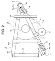
- a distance (L2) between a center of the first car guide rail 2 and a center of the first car return sheave 18 and a distance (L2) between a center of the second car guide rail 3 and a center of the second car return sheave 19 are equal when viewed from above, as also shown in Figure 2 .
- a distance (L3) between the counterweight suspension portion 7a and the first counterweight guide rail 4 and a distance (L3) between the counterweight suspension portion 7a and the second counterweight guide rail 5 are equal.
- a distance (L4) from a center of the counterweight return sheave 20 to the counterweight suspension portion 7a is significantly smaller than a distance (L5) from a center of the counterweight return sheave 20 to the center of the first car guide rail 2 (L4 ⁇ L5) when viewed from above.
- Figure 4 is an explanatory diagram that shows load sharing in the elevator apparatus in Figure 1 . Because the first and second car suspension portions 6e and 6f are disposed at positions that are of equal distance (L1) from the center of gravity of the car 6 when viewed from above, downward tensions that act on the first and second main ropes 16 and 17 due to the weight Wcar of the car 6 are each Wcar/2, and axle loads that act on the first and second car return sheaves 18 and 19 are also each Wcar/2. In other words, the amounts of weight from the car 6 that act on the first and second car return sheaves 18 and 19 are equal to each other.
- L4 is much smaller than L5
- f is significantly small.
- the axle load F that acts on the counterweight return sheave 20 is mainly supported by the first and second counterweight guide rails 4 and 5.
- the axle load F that acts on the counterweight return sheave 20 due to the weight Wcwt of the counterweight 7 is approximately equal to Wcwt.
- first and second car suspension portions 6e and 6f are disposed at positions that are equidistant from the center of gravity of the car 6, moments that are generated in a vicinity of the center of gravity due to deadweight from the car 6 can be suppressed, enabling reaction forces to which the car guide shoes (not shown) are subjected by the car guide rails 2 and 3 to be suppressed.
- running resistance and vibration are reduced, enabling riding comfort to be improved.
- first and second car suspension portions 6e and 6f are disposed so as to be distributed on two sides of an imaginary straight line that passes through the center of gravity of the car 6 and that is perpendicular to an imaginary straight line that connects the first and second car guide rails 2 and 3 when viewed from above, the car suspension portions 6e and 6f are disposed on two sides of the center of gravity even if the imaginary straight line that connects the car suspension portions 6e and 6f does not pass through the center of gravity of the car 6, enabling moments that are generated in the vicinity of the center of gravity due to deadweight from the car 6 to be suppressed.
- first and second car suspension portions 6e and 6f are disposed outside the handrail 22 on the car 6, the car suspension portions 6e and 6f will not obstruct work on the car 6, enabling a wide work area to be ensured.
- the selection conditions for the first and second counterweight guide rails 4 and 5 can be made similar, enabling minimization of the size of the counterweight guide rails 4 and 5.
- the loads that act on the first and second car guide rails 2 and 3 can be made uniform by supporting the weight of hoistway upper portion machinery (the driving machine 13, the supporting frame 8, and the inverting sheave 21, etc.) on the car guide rails 2 and 3 and adjusting the position of the hoistway upper portion machinery.
- hoistway upper portion machinery the driving machine 13, the supporting frame 8, and the inverting sheave 21, etc.
- the hoisting zone of the counterweight 7 was disposed beside the hoisting zone of the car 6, but the hoisting zone of a counterweight may also be disposed behind the hoisting zone of a car. In that case, the counterweight will be opposite the rear surface of the car when positioned level with the car.
Landscapes
- Engineering & Computer Science (AREA)
- Civil Engineering (AREA)
- Mechanical Engineering (AREA)
- Structural Engineering (AREA)
- Lift-Guide Devices, And Elevator Ropes And Cables (AREA)
Abstract
Description
- The present invention relates to an elevator apparatus in which a driving machine is disposed in an upper portion inside a hoistway.
- In conventional elevator apparatuses, first and second rope connecting portions are disposed on lower portions of two sides of a car. A driving machine that raises and lowers the car is disposed in an upper portion inside the hoistway. A main rope group that is wound around a drive sheave of the driving machine includes: a first main rope that is connected to the first rope connecting portion; and a second rope that is connected to the second rope connecting portion (see
Patent Document 1, for example). - Patent Document 1:
WO 03/074409 - In conventional elevator apparatuses such as that described above, because the first and second rope connecting portions are disposed on lower portions of the side surfaces of the car, it has been difficult to ensure space for performing replacement work on the main ropes, etc., inside narrow hoistways. Since the first and second rope connecting portions are disposed on a lower frame of the car, compressive load also acts on the car frame, requiring reinforcing materials such as diagonal members, etc., between the lower frame and a vertical frame of the car frame.
- The present invention aims to solve the above problems and an object of the present invention is to provide an elevator apparatus that can ensure space for replacement work on main ropes, etc., simply, and that also enables construction of a car frame to be simplified.
- In order to achieve the above object, according to one aspect of the present invention, there is provided an elevator apparatus including: a driving machine that has a drive sheave, and that is disposed in an upper portion inside a hoistway such that a rotating shaft of the drive sheave is vertical; a car that has first and second car suspension portions that are disposed so as to be spaced apart from each other, and that is raised and lowered by a driving force from the driving machine; a counterweight that has a counterweight suspension portion, and that is raised and lowered by a driving force from the driving machine; a first main rope that has: a first car end portion that is connected to the first car suspension portion; and a first counterweight end portion that is connected to the counterweight suspension portion, and that is wound around the drive sheave; and a second main rope that has: a second car end portion that is connected to the second car suspension portion; and a second counterweight end portion that is connected to the counterweight suspension portion, and that is wound around the drive sheave, wherein the first and second car suspension portions are disposed on an upper portion of the car, and are disposed at positions that are equidistant from a center of gravity of the car when viewed from above.
According to another aspect of the present invention, there is provided an elevator apparatus including: a driving machine that has a drive sheave, and that is disposed in an upper portion inside a hoistway such that a rotating shaft of the drive sheave is vertical; a car that has a plurality of car suspension portions that are disposed so as to be spaced apart from each other, and that is raised and lowered by a driving force from the driving machine; a counterweight that has a counterweight suspension portion, and that is raised and lowered by a driving force from the driving machine; and a plurality of main ropes that each have: a car end portion that is connected to the car suspension portion; and a counterweight end portion that is connected to the counterweight suspension portion, and that are wound around the drive sheave, wherein the car suspension portions are disposed on an upper portion of the car, and are disposed at positions that are equidistant from a center of gravity of the car when viewed from above.
According to another aspect of the present invention, there is provided an elevator apparatus including: a driving machine that has a drive sheave, and that is disposed in an upper portion inside a hoistway such that a rotating shaft of the drive sheave is vertical; a car that has first and second car suspension portions that are disposed so as to be spaced apart from each other, and that is raised and lowered by a driving force from the driving machine; a counterweight that has a counterweight suspension portion, and that is raised and lowered by a driving force from the driving machine; a first main rope that has: a first car end portion that is connected to the first car suspension portion; and a first counterweight end portion that is connected to the counterweight suspension portion, and that is wound around the drive sheave; a second main rope that has: a second car end portion that is connected to the second car suspension portion; and a second counterweight end portion that is connected to the counterweight suspension portion, and that is wound around the drive sheave; and first and second car guide rails that are installed inside the hoistway, and that guide raising and lowering of the car, wherein the first and second car suspension portions are disposed on an upper portion of the car, and are disposed so as to be distributed on two sides of an imaginary straight line that passes through a center of gravity of the car and that is perpendicular to an imaginary straight line that connects the first and second car guide rails when viewed from above.
According to another aspect of the present invention, there is provided an elevator apparatus including: a driving machine that has a drive sheave, and that is disposed in an upper portion inside a hoistway such that a rotating shaft of the drive sheave is vertical; a car that has a plurality of car suspension portions that are disposed so as to be spaced apart from each other, and that is raised and lowered by a driving force from the driving machine; a counterweight that has a counterweight suspension portion, and that is raised and lowered by a driving force from the driving machine; and a plurality of main ropes that each have: a car end portion that is connected to the car suspension portions; and a counterweight end portion that is connected to the counterweight suspension portion, and that are wound around the drive sheave, wherein a handrail that surrounds a working area on top of the car is disposed on an upper portion of the car; and the car suspension portions are disposed outside the handrail on an upper portion of the car.
According to another aspect of the present invention, there is provided an elevator apparatus including: a driving machine that has a drive sheave, and that is disposed in an upper portion inside a hoistway such that a rotating shaft of the drive sheave is vertical; a car that has: first and second car suspension portions that are disposed so as to be spaced apart from each other; and first and second side surfaces that are opposite each other, and that is raised and lowered by a driving force from the driving machine; a counterweight that has a counterweight suspension portion, and that is raised and lowered by a driving force from the driving machine; a first main rope that has: a first car end portion that is connected to the first car suspension portion; and a first counterweight end portion that is connected to the counterweight suspension portion, and that is wound around the drive sheave; and a second main rope that has: a second car end portion that is connected to the second car suspension portion and a second counterweight end portion that is connected to the counterweight suspension portion, and that is wound around the drive sheave, wherein the first car suspension portion is disposed in a region that is within 300 mm inward from the first side surface in a width direction of the car, and the second car suspension portion is disposed in a region that is within 300 mm inward from the second side surface in a width direction of the car when viewed from above. -
-
Figure 1 is a plan that shows an elevator apparatus according toEmbodiment 1 of the present invention; -
Figure 2 is a plan that shows part of the elevator apparatus inFigure 1 ; -
Figure 3 is a plan that shows part of the elevator apparatus inFigure 1 ; and -
Figure 4 is an explanatory diagram that shows load sharing in the elevator apparatus inFigure 1 . - A preferred embodiment of the present invention will now be explained with reference to the drawings.
-
Figure 1 is a plan that shows an elevator apparatus (a machine-roomless elevator) according toEmbodiment 1 of the present invention. In the figure, first and secondcar guide rails counterweight guide rails hoistway 1. Acar 6 is guided by thecar guide rails hoistway 1. Acounterweight 7 is guided by thecounterweight guide rails hoistway 1. - The
car 6 has: afront surface 6a in which a car entrance is disposed; arear surface 6b that is opposite thefront surface 6a; and first andsecond side surfaces counterweight 7 is disposed beside thecar 6 so as to face thesecond side surface 6d when positioned level with thecar 6. - The first
car guide rail 2 is opposite thefirst side surface 6c. The secondcar guide rail 3 is opposite thesecond side surface 6d. The first and secondcar guide rails car 6. Specifically, the firstcar guide rail 2 is disposed further back than center in the depth direction of thecar 6, and the secondcar guide rail 3 is disposed further forward than center in the depth direction of thecar 6. The first and secondcar guide rails car 6 when viewed from above. - In addition, the first and second
car guide rails car 6. Thecounterweight 7 is disposed in a space that is further back in the depth direction of thecar 6 than the secondcar guide rail 3. The first and secondcounterweight guide rails car 6. - A supporting
frame 8 is supported by upper portions of thecar guide rails counterweight guide rails frame 8 has: a V-shaped carreturn sheave beam 9; first and second rectilinear drivingmachine supporting beams sheave supporting portion 12. - The car
return sheave beam 9 is fixed to upper portions of the first and secondcar guide rails counterweight guide rail 5. The carreturn sheave beam 9 has: afirst end portion 9a that is fixed onto the secondcar guide rail 3; asecond end portion 9b that is fixed onto the secondcounterweight guide rail 5; and areturn portion 9c that is fixed onto the firstcar guide rail 2. - The driving
machine supporting beams return sheave beam 9 so as to be parallel to the depth direction of thecar 6. The counterweight return sheave beam 11 is fixed to thecounterweight guide rails car 6. The counterweight returnsheave supporting portion 12 is disposed so as to span between the first drivingmachine supporting beam 10b and the counterweight return sheave beam 11. - A
driving machine 13 that raises and lowers thecar 6 and thecounterweight 7 is supported by the drivingmachine supporting beams driving machine 13 has: a driving machinemain body 14 that includes a motor and a brake; and adrive sheave 15 that is rotated by the driving machinemain body 14. A thin hoisting machine in which an axial dimension is less than a dimension that is perpendicular to an axial direction is used for thedriving machine 13. - The
driving machine 13 is disposed in an upper portion inside thehoistway 1 such that a rotating shaft of thedrive sheave 15 is vertical (including approximately vertical). In addition, thedriving machine 13 is disposed such that thedrive sheave 15 is positioned above the driving machinemain body 14. - A plurality of first
main ropes 16 and a plurality of secondmain ropes 17 are wound around thedrive sheave 15. Thecar 6 and thecounterweight 7 are suspended inside thehoistway 1 by the first and secondmain ropes - A first
car suspension portion 6e that is connected to the firstmain ropes 16 and a secondcar suspension portion 6f that is connected to the secondmain ropes 17 are disposed on the upper portion of thecar 6. The first and secondcar suspension portions car 6. - The first and second
car suspension portions car 6 and that is perpendicular to an imaginary straight line that connects the first and secondcar guide rails handrail 22 that surrounds a working area on top of thecar 6 is disposed on an upper portion of thecar 6, and the first and secondcar suspension portions handrail 22 on an upper portion of thecar 6. The firstcar suspension portion 6e is disposed in a region that is within 300 mm inward from thefirst side surface 6c in a width direction of thecar 6, and the secondcar suspension portion 6f is disposed in a region that is within 300 mm inward from thesecond side surface 6d in a width direction of thecar 6 when viewed from above. - A
counterweight suspension portion 7a that is connected to the first and secondmain ropes counterweight 7. Thecounterweight suspension portion 7a is disposed on a central portion in a width direction of thecounterweight 7. - The first
main ropes 16 have: firstcar end portions 16a that are connected to the firstcar suspension portion 6e; and firstcounterweight end portions 16b that are connected to thecounterweight suspension portion 7a. The secondmain ropes 17 have: secondcar end portions 17a that are connected to the secondcar suspension portion 6f; and secondcounterweight end portions 17b that are connected to thecounterweight suspension portion 7a. - A first car return sheave 18 that directs the first
main ropes 16 toward the firstcar suspension portion 6e; a secondcar return sheave 19 that directs the secondmain ropes 17 toward the secondcar suspension portion 6f; acounterweight return sheave 20 that directs the first and secondmain ropes counterweight suspension portion 7a; and an invertingsheave 21 that directs the firstmain ropes 16 from the drive sheave 15 toward the firstcar return sheave 18 are disposed in an upper portion inside thehoistway 1. - The first and second
car return sheaves return sheave beam 9 such that rotating shafts thereof are horizontal. Thecounterweight return sheave 20 is supported by the counterweight return sheave supporting portion 11 such that a rotating shaft thereof is horizontal. The invertingsheave 21 is supported by the carreturn sheave beam 9 such that a rotating shaft thereof is vertical or approximately vertical. - The first and second
car suspension portions car 6 when viewed from above. The first and secondcar suspension portions car 6 are disposed in a straight line when viewed from above. In other words, the first and secondcar suspension portions car 6 when viewed from above. - In addition, a distance (L2) between a center of the first
car guide rail 2 and a center of the firstcar return sheave 18 and a distance (L2) between a center of the secondcar guide rail 3 and a center of the secondcar return sheave 19 are equal when viewed from above, as also shown inFigure 2 . - A distance (L3) between the
counterweight suspension portion 7a and the firstcounterweight guide rail 4 and a distance (L3) between thecounterweight suspension portion 7a and the secondcounterweight guide rail 5 are equal. - As also shown in
Figure 3 , a distance (L4) from a center of thecounterweight return sheave 20 to thecounterweight suspension portion 7a is significantly smaller than a distance (L5) from a center of thecounterweight return sheave 20 to the center of the first car guide rail 2 (L4 < L5) when viewed from above. -
Figure 4 is an explanatory diagram that shows load sharing in the elevator apparatus inFigure 1 . Because the first and secondcar suspension portions car 6 when viewed from above, downward tensions that act on the first and secondmain ropes car 6 are each Wcar/2, and axle loads that act on the first and second car return sheaves 18 and 19 are also each Wcar/2. In other words, the amounts of weight from thecar 6 that act on the first and second car return sheaves 18 and 19 are equal to each other. - Because the distance (L2) between the center of the first
car guide rail 2 and the center of the firstcar return sheave 18 and the distance (L2) between the center of the secondcar guide rail 3 and the center of the secondcar return sheave 19 are equal when viewed from above, the amounts of weight from thecar 6 that act on the first and secondcar guide rails - In addition, of an axle load F that acts on the
counterweight return sheave 20, a load f that acts on the firstcar guide rail 2 is given by f = {L4/(L4 + L5)} x F. However, since L4 is much smaller than L5, f is significantly small. Normally, if a width dimension of thecar 6 is greater than or equal to 1 m and a diameter of thecounterweight return sheave 20 is 0.2 m, then f will be approximately 10 percent of F. Consequently, the axle load F that acts on thecounterweight return sheave 20 is mainly supported by the first and secondcounterweight guide rails counterweight return sheave 20 due to the weight Wcwt of thecounterweight 7 is approximately equal to Wcwt. - Since the distance (L3) between the
counterweight suspension portion 7a and the firstcounterweight guide rail 4 and the distance (L3) between thecounterweight suspension portion 7a and the secondcounterweight guide rail 5 are equal, the amounts of weight from thecounterweight 7 that act on thecounterweight guide rails - In the above elevator apparatus, since the first and second
car suspension portions car 6, space for replacement work on themain ropes - Since the loads that act on the first and second
car guide rails car guide rails car guide rails car guide rails car guide rails hoistway 1 also to be reduced. - In addition, because the first and second
car suspension portions car 6, moments that are generated in a vicinity of the center of gravity due to deadweight from thecar 6 can be suppressed, enabling reaction forces to which the car guide shoes (not shown) are subjected by thecar guide rails - Because the first and second
car suspension portions car 6 and that is perpendicular to an imaginary straight line that connects the first and secondcar guide rails car suspension portions car suspension portions car 6, enabling moments that are generated in the vicinity of the center of gravity due to deadweight from thecar 6 to be suppressed. - Because the first and second
car suspension portions handrail 22 on thecar 6, thecar suspension portions car 6, enabling a wide work area to be ensured. - In addition, because shoulder width of an adult is approximately 600 to 700 mm, by disposing the
car suspension portions car 6, the deadweight of passengers will act further inside thecar 6 than thecar suspension portions car 6, enabling differences in tension between themain ropes main ropes car 6 to be reduced. - Since the load that results from the
counterweight 7 is supported mainly by the first and secondcounterweight guide rails counterweight guide rails counterweight guide rails counterweight guide rails - Moreover, even if the distances of the first and second car return sheaves 18 and 19 from the first and second
car guide rails car guide rails machine 13, the supportingframe 8, and the invertingsheave 21, etc.) on thecar guide rails - In the above example, the hoisting zone of the
counterweight 7 was disposed beside the hoisting zone of thecar 6, but the hoisting zone of a counterweight may also be disposed behind the hoisting zone of a car. In that case, the counterweight will be opposite the rear surface of the car when positioned level with the car.
In addition, there may also be three or more car suspension portions. In other words, a third car suspension portion, or fourth car suspension portion, etc., may also be disposed.
Claims (9)
- An elevator apparatus comprising:a driving machine that has a drive sheave, and that is disposed in an upper portion inside a hoistway such that a rotating shaft of the drive sheave is vertical;a car that has first and second car suspension portions that are disposed so as to be spaced apart from each other, and that is raised and lowered by a driving force from the driving machine;a counterweight that has a counterweight suspension portion, and that is raised and lowered by a driving force from the driving machine;a first main rope that has: a first car end portion that is connected to the first car suspension portion; and a first counterweight end portion that is connected to the counterweight suspension portion, and that is wound around the drive sheave; anda second main rope that has: a second car end portion that is connected to the second car suspension portion; and a second counterweight end portion that is connected to the counterweight suspension portion, and that is wound around the drive sheave, whereinthe first and second car suspension portions are disposed on an upper portion of the car, and are disposed at positions that are equidistant from a center of gravity of the car when viewed from above.
- The elevator apparatus according to Claim 1, wherein the first and second car suspension portions and the center of gravity of the car are disposed in a straight line when viewed from above.
- The elevator apparatus according to Claim 1, further comprising first and second car return sheaves that are disposed in an upper portion inside the hoistway and that direct the first and second main ropes toward the first and second car suspension portions, wherein
amounts of weight from the car that act on the first and second car return sheaves are equal to each other. - The elevator apparatus according to Claim 3, further comprising first and second car guide rails that are installed inside the hoistway, and that guide raising and lowering of the car, wherein
a load from the first car return sheave is supported by the first car guide rail,
a load from the second car return sheave is supported by the second car guide rail, and
a distance between the first car return sheave and the first car guide rail and a distance between the second car return sheave and the second car guide rail are equal when viewed from above. - The elevator apparatus according to Claim 1, further comprising:a counterweight return sheave that is disposed in an upper portion inside the hoistway, and that directs the first and second main ropes toward the counterweight suspension portion; andfirst and second counterweight guide rails that are installed inside the hoistway, and that guide raising and lowering of the counterweight, whereina distance between the counterweight suspension portion and the first counterweight guide rail and a distance between the counterweight suspension portion and the second counterweight guide rail are equal, andweight from the counterweight that acts on the counterweight return sheave is supported by the first and second counterweight guide rails.
- An elevator apparatus comprising:a driving machine that has a drive sheave, and that is disposed in an upper portion inside a hoistway such that a rotating shaft of the drive sheave is vertical;a car that has a plurality of car suspension portions that are disposed so as to be spaced apart from each other, and that is raised and lowered by a driving force from the driving machine;a counterweight that has a counterweight suspension portion, and that is raised and lowered by a driving force from the driving machine; anda plurality of main ropes that each have: a car end portion that is connected to the car suspension portion; and a counterweight end portion that is connected to the counterweight suspension portion, and that are wound around the drive sheave, whereinthe car suspension portions are disposed on an upper portion of the car, and are disposed at positions that are equidistant from a center of gravity of the car when viewed from above.
- An elevator apparatus comprising:a driving machine that has a drive sheave, and that is disposed in an upper portion inside a hoistway such that a rotating shaft of the drive sheave is vertical;a car that has first and second car suspension portions that are disposed so as to be spaced apart from each other, and that is raised and lowered by a driving force from the driving machine;a counterweight that has a counterweight suspension portion, and that is raised and lowered by a driving force from the driving machine;a first main rope that has: a first car end portion that is connected to the first car suspension portion; and a first counterweight end portion that is connected to the counterweight suspension portion, and that is wound around the drive sheave;a second main rope that has: a second car end portion that is connected to the second car suspension portion; and a second counterweight end portion that is connected to the counterweight suspension portion, and that is wound around the drive sheave; andfirst and second car guide rails that are installed inside the hoistway, and that guide raising and lowering of the car, whereinthe first and second car suspension portions are disposed on an upper portion of the car, and are disposed so as to be distributed on two sides of an imaginary straight line that that passes through a center of gravity of the car and that is perpendicular to an imaginary straight line that connects the first and second car guide rails when viewed from above.
- An elevator apparatus comprising:a driving machine that has a drive sheave, and that is disposed in an upper portion inside a hoistway such that a rotating shaft of the drive sheave is vertical;a car that has a plurality of car suspension portions that are disposed so as to be spaced apart from each other, and that is raised and lowered by a driving force from the driving machine;a counterweight that has a counterweight suspension portion, and that is raised and lowered by a driving force from the driving machine; anda plurality of main ropes that each have: a car end portion that is connected to the car suspension portions; and a counterweight end portion that is connected to the counterweight suspension portion, and that are wound around the drive sheave, whereina handrail that surrounds a working area on top of the car is disposed on an upper portion of the car, andthe car suspension portions are disposed outside the handrail on an upper portion of the car.
- An elevator apparatus comprising:a driving machine that has a drive sheave, and that is disposed in an upper portion inside a hoistway such that a rotating shaft of the drive sheave is vertical;a car that has: first and second car suspension portions that are disposed so as to be spaced apart from each other; and first and second side surfaces that are opposite each other, and that is raised and lowered by a driving force from the driving machine;a counterweight that has a counterweight suspension portion, and that is raised and lowered by a driving force from the driving machine;a first main rope that has: a first car end portion that is connected to the first car suspension portion; and a first counterweight end portion that is connected to the counterweight suspension portion, and that is wound around the drive sheave; anda second main rope that has: a second car end portion that is connected to the second car suspension portion and a second counterweight end portion that is connected to the counterweight suspension portion, and that is wound around the drive sheave, whereinthe first car suspension portion is disposed in a region that is within 300 mm inward from the first side surface in a width direction of the car, and the second car suspension portion is disposed in a region that is within 300 mm inward from the second side surface in a width direction of the car when viewed from above.
Applications Claiming Priority (1)
| Application Number | Priority Date | Filing Date | Title |
|---|---|---|---|
| PCT/JP2005/013147 WO2007010589A1 (en) | 2005-07-15 | 2005-07-15 | Elevator apparatus |
Publications (2)
| Publication Number | Publication Date |
|---|---|
| EP1905719A1 true EP1905719A1 (en) | 2008-04-02 |
| EP1905719A4 EP1905719A4 (en) | 2013-02-27 |
Family
ID=37668478
Family Applications (1)
| Application Number | Title | Priority Date | Filing Date |
|---|---|---|---|
| EP05766225A Withdrawn EP1905719A4 (en) | 2005-07-15 | 2005-07-15 | ELEVATOR APPARATUS |
Country Status (4)
| Country | Link |
|---|---|
| EP (1) | EP1905719A4 (en) |
| JP (1) | JPWO2007010589A1 (en) |
| CN (1) | CN101010250A (en) |
| WO (1) | WO2007010589A1 (en) |
Family Cites Families (6)
| Publication number | Priority date | Publication date | Assignee | Title |
|---|---|---|---|---|
| JPH0570057A (en) * | 1991-09-17 | 1993-03-23 | Hitachi Building Syst Eng & Service Co Ltd | Elevator device |
| JPH107343A (en) * | 1996-06-24 | 1998-01-13 | Hitachi Ltd | elevator |
| JP4110096B2 (en) * | 2002-03-01 | 2008-07-02 | 三菱電機株式会社 | Elevator equipment |
| KR100697487B1 (en) * | 2002-06-21 | 2007-03-20 | 미쓰비시덴키 가부시키가이샤 | Elevator device |
| WO2006040813A1 (en) * | 2004-10-13 | 2006-04-20 | Mitsubishi Denki Kabushiki Kaisha | Elevator apparatus |
| JPWO2006129358A1 (en) * | 2005-06-02 | 2008-12-25 | 三菱電機株式会社 | Elevator equipment |
-
2005
- 2005-07-15 JP JP2006538574A patent/JPWO2007010589A1/en active Pending
- 2005-07-15 WO PCT/JP2005/013147 patent/WO2007010589A1/en not_active Ceased
- 2005-07-15 EP EP05766225A patent/EP1905719A4/en not_active Withdrawn
- 2005-07-15 CN CNA200580029368XA patent/CN101010250A/en active Pending
Also Published As
| Publication number | Publication date |
|---|---|
| WO2007010589A1 (en) | 2007-01-25 |
| CN101010250A (en) | 2007-08-01 |
| JPWO2007010589A1 (en) | 2009-01-29 |
| EP1905719A4 (en) | 2013-02-27 |
Similar Documents
| Publication | Publication Date | Title |
|---|---|---|
| JP5805212B2 (en) | Elevator equipment | |
| JP5889412B2 (en) | Elevator suspension structure and guide shoe structure | |
| EP1471026A9 (en) | Elevator device | |
| US20110108366A1 (en) | Elevator apparatus | |
| EP1693328B1 (en) | Elevator apparatus | |
| US8172041B2 (en) | Machine room-less elevator | |
| US20050178621A1 (en) | Elevator | |
| CN104428235A (en) | Elevator device | |
| EP1568644B9 (en) | Elevator equipment | |
| EP1961688A1 (en) | Elevator device | |
| EP1905719A1 (en) | Elevator apparatus | |
| EP1717184B1 (en) | Elevator | |
| JP2011051736A (en) | Elevator device | |
| US20070170005A1 (en) | Machine room-less elevator | |
| EP1930283A1 (en) | Elevator device | |
| JP7799555B2 (en) | elevator equipment | |
| EP1571113A1 (en) | Elevator equipment | |
| CN103863919A (en) | Load support beam holding device of elevator | |
| CN112141860B (en) | Counterweight side-drop elevator structure | |
| CN103068712B (en) | Elevator device | |
| JPWO2019116467A1 (en) | Machine roomless elevator | |
| KR20070065322A (en) | Elevator device | |
| HK1230567A1 (en) | Machine room-less elevator refurbishing method | |
| HK1219084B (en) | Elevator without machine room and method of retrofitting the same | |
| HK1219084A1 (en) | Elevator without machine room and method of retrofitting the same |
Legal Events
| Date | Code | Title | Description |
|---|---|---|---|
| PUAI | Public reference made under article 153(3) epc to a published international application that has entered the european phase |
Free format text: ORIGINAL CODE: 0009012 |
|
| 17P | Request for examination filed |
Effective date: 20070306 |
|
| AK | Designated contracting states |
Kind code of ref document: A1 Designated state(s): DE |
|
| RBV | Designated contracting states (corrected) |
Designated state(s): DE |
|
| DAX | Request for extension of the european patent (deleted) | ||
| A4 | Supplementary search report drawn up and despatched |
Effective date: 20130130 |
|
| RIC1 | Information provided on ipc code assigned before grant |
Ipc: B66B 11/00 20060101ALI20130123BHEP Ipc: B66B 7/06 20060101AFI20130123BHEP |
|
| STAA | Information on the status of an ep patent application or granted ep patent |
Free format text: STATUS: THE APPLICATION IS DEEMED TO BE WITHDRAWN |
|
| 18D | Application deemed to be withdrawn |
Effective date: 20130829 |