EP1905593A1 - Ink-jet head - Google Patents
Ink-jet head Download PDFInfo
- Publication number
- EP1905593A1 EP1905593A1 EP07019207A EP07019207A EP1905593A1 EP 1905593 A1 EP1905593 A1 EP 1905593A1 EP 07019207 A EP07019207 A EP 07019207A EP 07019207 A EP07019207 A EP 07019207A EP 1905593 A1 EP1905593 A1 EP 1905593A1
- Authority
- EP
- European Patent Office
- Prior art keywords
- plate
- recesses
- fluid communication
- flow channel
- inkjet head
- Prior art date
- Legal status (The legal status is an assumption and is not a legal conclusion. Google has not performed a legal analysis and makes no representation as to the accuracy of the status listed.)
- Granted
Links
Images


Classifications
-
- B—PERFORMING OPERATIONS; TRANSPORTING
- B41—PRINTING; LINING MACHINES; TYPEWRITERS; STAMPS
- B41J—TYPEWRITERS; SELECTIVE PRINTING MECHANISMS, i.e. MECHANISMS PRINTING OTHERWISE THAN FROM A FORME; CORRECTION OF TYPOGRAPHICAL ERRORS
- B41J2/00—Typewriters or selective printing mechanisms characterised by the printing or marking process for which they are designed
- B41J2/005—Typewriters or selective printing mechanisms characterised by the printing or marking process for which they are designed characterised by bringing liquid or particles selectively into contact with a printing material
- B41J2/01—Ink jet
- B41J2/135—Nozzles
- B41J2/16—Production of nozzles
- B41J2/1621—Manufacturing processes
- B41J2/1623—Manufacturing processes bonding and adhesion
-
- B—PERFORMING OPERATIONS; TRANSPORTING
- B41—PRINTING; LINING MACHINES; TYPEWRITERS; STAMPS
- B41J—TYPEWRITERS; SELECTIVE PRINTING MECHANISMS, i.e. MECHANISMS PRINTING OTHERWISE THAN FROM A FORME; CORRECTION OF TYPOGRAPHICAL ERRORS
- B41J2/00—Typewriters or selective printing mechanisms characterised by the printing or marking process for which they are designed
- B41J2/005—Typewriters or selective printing mechanisms characterised by the printing or marking process for which they are designed characterised by bringing liquid or particles selectively into contact with a printing material
- B41J2/01—Ink jet
- B41J2/135—Nozzles
- B41J2/14—Structure thereof only for on-demand ink jet heads
- B41J2/14201—Structure of print heads with piezoelectric elements
- B41J2/14209—Structure of print heads with piezoelectric elements of finger type, chamber walls consisting integrally of piezoelectric material
-
- B—PERFORMING OPERATIONS; TRANSPORTING
- B41—PRINTING; LINING MACHINES; TYPEWRITERS; STAMPS
- B41J—TYPEWRITERS; SELECTIVE PRINTING MECHANISMS, i.e. MECHANISMS PRINTING OTHERWISE THAN FROM A FORME; CORRECTION OF TYPOGRAPHICAL ERRORS
- B41J2/00—Typewriters or selective printing mechanisms characterised by the printing or marking process for which they are designed
- B41J2/005—Typewriters or selective printing mechanisms characterised by the printing or marking process for which they are designed characterised by bringing liquid or particles selectively into contact with a printing material
- B41J2/01—Ink jet
- B41J2/135—Nozzles
- B41J2/16—Production of nozzles
- B41J2/1607—Production of print heads with piezoelectric elements
- B41J2/1609—Production of print heads with piezoelectric elements of finger type, chamber walls consisting integrally of piezoelectric material
-
- B—PERFORMING OPERATIONS; TRANSPORTING
- B41—PRINTING; LINING MACHINES; TYPEWRITERS; STAMPS
- B41J—TYPEWRITERS; SELECTIVE PRINTING MECHANISMS, i.e. MECHANISMS PRINTING OTHERWISE THAN FROM A FORME; CORRECTION OF TYPOGRAPHICAL ERRORS
- B41J2/00—Typewriters or selective printing mechanisms characterised by the printing or marking process for which they are designed
- B41J2/005—Typewriters or selective printing mechanisms characterised by the printing or marking process for which they are designed characterised by bringing liquid or particles selectively into contact with a printing material
- B41J2/01—Ink jet
- B41J2/135—Nozzles
- B41J2/14—Structure thereof only for on-demand ink jet heads
- B41J2/14201—Structure of print heads with piezoelectric elements
- B41J2/14209—Structure of print heads with piezoelectric elements of finger type, chamber walls consisting integrally of piezoelectric material
- B41J2002/14217—Multi layer finger type piezoelectric element
-
- B—PERFORMING OPERATIONS; TRANSPORTING
- B41—PRINTING; LINING MACHINES; TYPEWRITERS; STAMPS
- B41J—TYPEWRITERS; SELECTIVE PRINTING MECHANISMS, i.e. MECHANISMS PRINTING OTHERWISE THAN FROM A FORME; CORRECTION OF TYPOGRAPHICAL ERRORS
- B41J2/00—Typewriters or selective printing mechanisms characterised by the printing or marking process for which they are designed
- B41J2/005—Typewriters or selective printing mechanisms characterised by the printing or marking process for which they are designed characterised by bringing liquid or particles selectively into contact with a printing material
- B41J2/01—Ink jet
- B41J2/135—Nozzles
- B41J2/14—Structure thereof only for on-demand ink jet heads
- B41J2/14201—Structure of print heads with piezoelectric elements
- B41J2/14209—Structure of print heads with piezoelectric elements of finger type, chamber walls consisting integrally of piezoelectric material
- B41J2002/14225—Finger type piezoelectric element on only one side of the chamber
-
- B—PERFORMING OPERATIONS; TRANSPORTING
- B41—PRINTING; LINING MACHINES; TYPEWRITERS; STAMPS
- B41J—TYPEWRITERS; SELECTIVE PRINTING MECHANISMS, i.e. MECHANISMS PRINTING OTHERWISE THAN FROM A FORME; CORRECTION OF TYPOGRAPHICAL ERRORS
- B41J2/00—Typewriters or selective printing mechanisms characterised by the printing or marking process for which they are designed
- B41J2/005—Typewriters or selective printing mechanisms characterised by the printing or marking process for which they are designed characterised by bringing liquid or particles selectively into contact with a printing material
- B41J2/01—Ink jet
- B41J2/135—Nozzles
- B41J2/14—Structure thereof only for on-demand ink jet heads
- B41J2/14201—Structure of print heads with piezoelectric elements
- B41J2002/14306—Flow passage between manifold and chamber
-
- B—PERFORMING OPERATIONS; TRANSPORTING
- B41—PRINTING; LINING MACHINES; TYPEWRITERS; STAMPS
- B41J—TYPEWRITERS; SELECTIVE PRINTING MECHANISMS, i.e. MECHANISMS PRINTING OTHERWISE THAN FROM A FORME; CORRECTION OF TYPOGRAPHICAL ERRORS
- B41J2/00—Typewriters or selective printing mechanisms characterised by the printing or marking process for which they are designed
- B41J2/005—Typewriters or selective printing mechanisms characterised by the printing or marking process for which they are designed characterised by bringing liquid or particles selectively into contact with a printing material
- B41J2/01—Ink jet
- B41J2/135—Nozzles
- B41J2/14—Structure thereof only for on-demand ink jet heads
- B41J2002/14459—Matrix arrangement of the pressure chambers
-
- B—PERFORMING OPERATIONS; TRANSPORTING
- B41—PRINTING; LINING MACHINES; TYPEWRITERS; STAMPS
- B41J—TYPEWRITERS; SELECTIVE PRINTING MECHANISMS, i.e. MECHANISMS PRINTING OTHERWISE THAN FROM A FORME; CORRECTION OF TYPOGRAPHICAL ERRORS
- B41J2202/00—Embodiments of or processes related to ink-jet or thermal heads
- B41J2202/01—Embodiments of or processes related to ink-jet heads
- B41J2202/11—Embodiments of or processes related to ink-jet heads characterised by specific geometrical characteristics
-
- B—PERFORMING OPERATIONS; TRANSPORTING
- B41—PRINTING; LINING MACHINES; TYPEWRITERS; STAMPS
- B41J—TYPEWRITERS; SELECTIVE PRINTING MECHANISMS, i.e. MECHANISMS PRINTING OTHERWISE THAN FROM A FORME; CORRECTION OF TYPOGRAPHICAL ERRORS
- B41J2202/00—Embodiments of or processes related to ink-jet or thermal heads
- B41J2202/01—Embodiments of or processes related to ink-jet heads
- B41J2202/20—Modules
Definitions
- the present invention relates to an ink-jet head that discharges ink on a recording medium.
- a known ink-jet head includes a cavity plate formed of five plates piled and bonded together with adhesive agent, and a piezoelectric actuator bonded to the cavity plate.
- a base plate included in the cavity plate the ink-jet head includes pressure chambers, distal end flow channels formed at one end of the respective pressure chambers, opposite end flow channels formed at the other ends of the respective pressure chambers, and elongated portions serving as ink flow channels for placing the pressure chamber and the opposite end flow channels in fluid communication.
- the base plate includes opposing release grooves formed between the elongated portions, and substantially arcuate-shaped release grooves surrounding a side edge of each of the opposite end flow channels. The opposing release grooves are in fluid communication via release holes which penetrate through the base plate.
- the release grooves formed between the squeezed portions may not connect to the arcuate-shaped release grooves.
- air in the release grooves may be trapped when the base plate and the spacer plate are bonded with the adhesive agent, and the excessive adhesive agent may be attracted toward the squeezed portions where air tends to be released, and the excessive adhesive agent may clog the elongated portions.
- An embodiment of the invention describes an inkjet head comprising a flow channel unit, the flow channel unit comprising a plurality of laminated plates comprising a first plate, a second plate, and a third plate, wherein the plurality of laminated plates is configured to form a common ink chamber, a plurality of nozzles, and a plurality of pressure chambers therethrough, and a plurality of individual ink flow channels, each individual ink flow channel configured to extend from the common ink chamber to one of the plurality of nozzles via one of the plurality of pressure chambers.
- the first plate comprises a plurality of apertures configured to place the common ink chamber and the pressure chambers in fluid communication, and a surface of the first plate adjacent to the second plate has a plurality of first recesses extending away from the second plate.
- the first recesses are configured to be in fluid communication with the atmosphere, and a plurality of second recesses extending toward the third plate, and the second recesses being surrounded by the plurality of apertures.
- a surface of the third plate has a plurality of third recesses extending away from the first plate, and an opposite surface of the first plate has a plurality of openings therethrough. The plurality of openings is configured to place the first and second recesses in fluid communication with the third recesses of the third plate.
- an inkjet head comprising a flow channel unit, the flow channel unit comprising a plurality of laminated plates comprising a first plate and a second plate, wherein the plurality of laminated plates is configured to form a common ink chamber, a plurality of nozzles, and a plurality of pressure chambers therethrough; and a plurality of individual ink flow channels, each individual ink flow channel configured to extend from the common ink chamber to one of the plurality of nozzles via one of the plurality of pressure chambers.
- the first plate comprises a plurality of apertures configured to place the common ink chambers and the pressure chambers in fluid communication
- a surface of the first plate adjacent to the second plate comprises a plurality of first recesses extending away from the second plate.
- the first recesses are configured to be in fluid communication with the atmosphere, and a plurality of second recesses extending away from the second plate, and the second recesses are surrounded by the plurality of apertures.
- a surface of the second plate comprises a plurality of third recesses extending away from the first plate, each of the plurality of third recesses opposing a portion of one of the plurality of first recesses and a portion of one of the plurality of fourth recesses.
- the third recesses are configured to be in fluid communication with the respective portions of each of the plurality of first and second recesses.
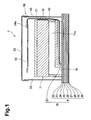
- Fig. 1 is a vertical cross-sectional view of an ink-jet head according to an embodiment of the invention.
- Fig. 2 is a plan view of a head body as shown in Fig. 1.
- Fig. 3 is an enlarged view of an area S 1 surrounded by a dashed line shown in Fig. 2.
- Fig. 4 is a cross-sectional view taken along the line IV-IV in Fig. 3.
- Fig. 5 is a partly enlarged view of an aperture plate in an area S2 surrounded by the dashed line shown in Fig. 2.
- Fig. 6 is a partly enlarged view of a base plate in an area S2 surrounded by the dashed line shown in Fig. 2.
- Fig. 7A is a partly enlarged view showing an area surrounded by a dashed line shown in Fig. 5.
- Fig. 7B is a partly enlarged view showing an area surrounded by a dashed line shown in Fig. 6.
- Fig. 8 is a partial cross-sectional view showing a state in which the base plate and the aperture plate are laminated, according to an embodiment of the invention.
- Fig. 9 is an exploded perspective view of the base plate and the aperture plate shown in Fig. 8.
- Fig. 10A is a partly enlarged cross-sectional view of an actuator unit and a pressure chamber according to an embodiment of the invention.
- Fig. 10B is a plan view of the shape of the individual electrode bonded to the surface of the actuator unit according to an embodiment of the invention.
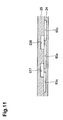
- Fig. 11 is a partial cross-sectional view showing a state in which the aperture plate and a supply plate of an ink-jet head are laminated, according to another embodiment of the invention.
- an ink-jet head 1 may include a head body 70 for discharging ink, a reservoir unit 71, which may be arranged on the upper surface of head body 70, a flexible printed circuit (FPC) 50 electrically connected to head body 70, and a control board 54 electrically connected to FPC 50.
- Head body 70 may include a flow channel unit 4 formed with an ink flow channel in the interior thereof, and an actuator unit 21.
- FPC 50 may be provided with a driver IC 52 configured to supply drive signals.
- Driver IC 52 may be mounted substantially at the middle of FPC 50, and may be connected to the upper surface of actuator 21.
- Head body 70 may be configured so that actuator unit 21 may be arranged on the upper surface of flow channel unit 4.
- a plurality of, e.g., ten, ink supply ports 5b may be in fluid communication with the ink flow channels in the interior of flow channel unit 4, and may be formed on the upper surface of the flow channel unit 4.
- the ink flow channels may include pressure chambers 10 formed on the upper surface of flow channel unit 4, and ink discharge nozzles 8 in fluid communication with pressure chambers 10.
- Control board 54 may be arranged horizontally above reservoir unit 71, and the other end of FPC 50 may be connected thereto, via a connector 54a.
- Driver IC 52 may be adapted to supply drive signals to the actuator unit 21 via a wiring line, e.g., a signal line, of the FPC 50 on the basis of the command from the control board 54.
- Reservoir unit 71 may include an ink reservoir 71 a for storing ink therein, and ink reservoir 71 a may be in fluid communication with ink supply ports 5b of flow channel unit 4. Therefore, ink in ink reservoir 71a may be supplied to the ink flow channels in flow channel unit 4 via ink supply ports 5b.
- Actuator unit 21, reservoir unit 71, control board 54, and FPC 50 may be covered by a cover member 58.
- Cover member 58 may include a side cover 53, and a head cover 55, and may be positioned to prevent entry of ink or ink mist present around the exterior of cover member 58.
- Cover member 58 may be formed of any suitable metallic material.
- Reservoir unit 71 may be provided with a sponge 51, having resilience on a side surface thereof.
- driver IC 52 on FPC 50 may be mounted so as to oppose sponge 51, and driver IC 52 may be pressed against the inner surface of side cover 53 by sponge 51. Heat generated in the driver IC 52 may be transmitted to head cover 55 via side cover 53, and may be discharged to the atmosphere via metallic cover member 58.
- flow channel unit 4 of head body 70 may be formed with a number of pressure chambers 10 and a number of nozzles 8 being in fluid communication with a number of pressure chambers 10.
- the respective pressure chambers 10 may have a substantially diamond shape, having portions at an acute angle at both longitudinal ends, and also having portions at an obtuse angle at both widthwise ends, e.g., a parallelogram with rounded corners.
- a number of pressure chambers 10 may be arranged adjacently on the upper surface of flow channel unit 4 in two directions, e.g., in the direction of arrangement A and in the direction of arrangement B, in a matrix pattern.
- the direction of arrangement A may be a longitudinal direction of flow channel unit 4, and may extend in parallel to a shorter diagonal line of pressure chamber 10.
- the direction of arrangement B may correspond to the direction of an oblique line of pressure chamber 10, forming an obtuse angle ⁇ with respect to the direction of arrangement A.
- Pressure chambers 10 may be arranged in a matrix pattern in the directions of arrangement A and in the direction of arrangement B. Along the direction of arrangement A, pressure chambers 10 may be spaced apart from each other at a distance which corresponds to an output print resolution of 37.5 Dots Per Inch (DPI).
- a plurality of, e.g., sixteen, pressure chambers 10 may be arranged in the direction of arrangement B in an ink discharge area, described in more detail herein.
- the plurality of pressure chambers 10 may be grouped in a pressure chamber group 9, as shown in Fig. 2 .
- a plurality of, e.g., four, actuator units 21 may be bonded to the upper surface of flow channel unit 4.
- the plurality of actuator units may be arranged into two offset, zigzagging rows, corresponding to the arrangement of pressure chamber groups 9.
- Pressure chamber groups 9 and actuator units 21 each may have a trapezoidal outline shape, as shown in Fig. 2 .
- the lower surface of flow channel unit 4, which may oppose the bonding area of actuator unit 21, may correspond to an ink discharge area, including a number of nozzles 8 arranged therein.
- Nozzles 8 also may be arranged in a matrix pattern and constitute a plurality of nozzle rows. As shown in Fig. 3 , in an embodiment, a plurality of, .e.g., sixteen rows of pressure chambers 10 may be arranged in a longitudinal direction of flow channel unit 4, and may be arranged equidistantly and parallel to each other, in the widthwise direction of flow channel unit 4. The number of pressure chambers 10 located in each pressure chamber row decreases gradually from the long side to the short side of pressure chamber group 9, corresponding to the outline shape of actuator unit 21. Nozzles 8 may be arranged in the same manner as pressure chambers 10. Accordingly, image formation at a specific resolution, e.g., 600 DPI, may be achieved.
- Fig. 3 represents actuator units 21 with double dashed chain lines, and pressure chambers 10 and apertures 12, which normally would appear with broken lines, since they may be located below actuator units 21, are drawn in solid lines.
- manifold flow channels 5 may continue to ink supply ports 5b, and common ink chambers, e.g., sub-manifold flow channels 5a, branched from the manifold flow channels 5, may be formed in flow channel unit 4.
- Manifold flow channels 5 may extend along the oblique sides of actuator units 21.
- one manifold flow channel 5 may be used by both adjacent actuator units 21, and sub-manifold flow channels 5a may be branched from both sides of manifold flow channel 5.
- Sub-manifold flow channels 5a may extend in the longitudinal direction of flow channel unit 4.
- a number of nozzles 8 may be arranged in the longitudinal direction of flow channel unit 4, as shown in Fig. 3 .
- Respective nozzles 8 may be in fluid communication with pressure chambers 10, and with sub-manifold flow channels 5a, via holes or squeezed flow channels, e.g., apertures 12.
- head body 70 may be formed by bonding flow channel unit 4 and actuator unit 21.
- Flow channel unit 4 may have a laminated structure in which a plurality of, e.g., nine, metal plates may be laminated together.
- the plurality of metal plates may include, in order from top to bottom, a cavity plate 22, a base plate, e.g., a third plate 23, an aperture plate, e.g., a first plate 24, a supply plate, e.g., a second plate 25, manifold plates 26, 27, and 28, a cover plate 29, and a nozzle plate 30.
- Cavity plate 22 may comprise any known metal, and may have a number of openings having a substantially diamond shape. Each opening may correspond to a location of a pressure chamber 10.
- Base plate 23 may comprise any known metal, and may have a communication opening 23a between pressure chamber 10 and aperture 12, and another communication hole 23b connecting pressure chamber 10 to nozzle 8, respectively corresponding to the location of pressure chamber 10 of the cavity plate 22.
- Aperture plate 24 may comprise any known metal, and, as shown in more detail in Fig. 3 and Fig. 7 , may include aperture 12. Referring again to Fig. 4 , aperture 12 may have a communicating portion 12c in fluid communication with an ink inlet port 12a on the side of sub-manifold flow channel 5a, and an ink outlet port 12b on the side of pressure chamber 10. Aperture plate 24 also may include a communication hole 12d, narrower than communication portion 12c, placing pressure chamber 10 in fluid communication with nozzle 8.
- Supply plate 25 may comprise any known metal, and may have a communication opening 25a between aperture 12 and sub-manifold flow channel 5a, and another communication opening 25b from pressure chamber 10 to nozzle 8.
- Manifold plates 26, 27, and 28 may comprise any known metal, and may include a communication opening from pressure chamber 10 to nozzle 8, respectively, corresponding to pressure chamber 10 of cavity plate 22, in addition to sub-manifold flow channels 5a.
- Cover plate 29 may comprise any known metal, and may include communication openings from pressure chambers 10 to nozzles 8, corresponding to pressure chamber 10 of cavity plate 22.
- Nozzle plate 30 may comprise any known metal, and may include nozzles 8, corresponding to pressure chamber 10 of cavity plate 22.
- base plate 23, aperture plate 24, and supply plate 25 each may be formed with openings 5c and 5d for ink supply port 5b and manifold flow channel 5.
- nine plates 22 to 30 may be aligned with each other and laminated so that an individual ink flow channel 32 may be formed, as shown in Fig. 4 .
- Individual ink flow channel 32 may extend from the exit of sub-manifold flow channel 5a upward, extend horizontally in aperture 12, then extends further upward and horizontally again in pressure chamber 10, then extend obliquely downward in a direction away from aperture 12, and finally extend vertically downward toward nozzle 8.
- the opening which corresponds to pressure chamber 10 formed on cavity plate 22 may be closed partly by base plate 23, so that an opening of pressure chamber 10 formed as a recess may be formed on the upper surface of flow channel unit 4.
- actuator unit 21 may be bonded to the upper surface of flow channel unit 21, so as to close the opening of pressure chamber 10.
- pressure chamber 10 and aperture 12 may be provided at different levels.
- aperture 12, which may be in fluid communication with one pressure chamber 10 may be arranged at the same position as another pressure chamber 10, adjacent to the pressure chamber shown in plan view in flow channel unit 4, corresponding to the ink discharge area located below actuator unit 21.
- Pressure chambers 10 may be arranged closely to each other at a high density, which may allow ink-jet head 1 to perform image printing at a high resolution, while maintaining a minimal occupancy area.
- a plurality of apertures 12 and communication holes 12d may be formed in areas which overlap actuator units 21, similarly to the overlapping of the plurality of pressure chambers 10.
- apertures 12 may be arranged adjacent to each other in a matrix pattern, in the direction of arrangement A, and the direction of arrangement B
- a plurality of, e.g., sixteen, apertures 12 may be included in the direction of arrangement B.
- the arrangement of communication holes 12d may be slightly different.
- communication holes 12d may be adjacently arranged in the direction of arrangement A and the direction of arrangement B in a matrix pattern, eight communication holes 12d may be included in the direction of arrangement B.
- a set of two rows, each row including eight communication holes 12d, may correspond to sixteen pressure chambers 10, arranged in the direction of arrangement B.
- the plurality of apertures 12 may be divided into a plurality of, e.g., four, aperture rows 112a to 112d, arranged along the direction of arrangement A.
- Aperture rows 112a to 112d may be repeatedly arranged from one end to the other end of aperture plate 24 in either direction orthogonal to the direction of arrangement A of aperture plate 24.
- ink outlet ports 12b of apertures 12 may be arranged on the right side in aperture rows 112b and 112d, and on the left side in aperture rows 112a and 112c.
- Ink inlet ports 12a of apertures 12 may be located on the opposite sides of ink outlet ports 12b of apertures 12, in the respective aperture rows 112a to 112d.
- Communicating portions 12c located between ink inlet ports 12a and ink outlet ports 12b of apertures 12, may have a smaller short-side width than the widths of ink inlet ports 12a and ink outlet ports 12b, when viewed in plan view. Communicating portions 12c also may be formed to be the smallest in cross-sectional area for ink passage in individual ink flow channel 32, so that the resistance of the ink flow channel between sub-manifold flow channels 5a to pressure chambers 10 may be regulated. As shown in Fig. 5 , along the outermost periphery of the plurality of apertures 12 and communication holes 12d, on the surface of aperture plate 24 on the side of supply plate 25, a surrounding groove 61 having a shape corresponding thereto may be formed.
- Opening surrounding groove 62 may be formed on the outer periphery of each opening 5d of aperture plate 24, and conforming to the outer peripheral shape of opening 5d, and having a bonding margin of a predetermined width. Opening surrounding groove 62 may include opening surrounding groove 62a at a position closest to opening 5d, and opening surrounding grooves 62b and 62c may be enlarged from secondary opening surrounding groove 62a, in sequence. Connecting grooves 63 may be formed into a lattice pattern, and connected to surrounding groove 61. Opening surrounding grooves 62c may be formed over the entire surface of aperture plate 24, on the side of supply plate 25, except for the areas inside surrounding groove 61 and inside opening surrounding groove 62. As shown in Fig. 5, aperture plate 24 may be formed with a through hole 59, located at a lower left position when aperture plate is positioned as shown in Fig. 5 .
- Through hole 59 and connecting groove 63 may be in fluid communication with each other.
- through holes 57 and 58 may be formed on cavity plate 22 and base plate 23, at similar positions to that of through hole 59 on aperture plate 24.
- Through holes 57, 58, and 59 may be positioned so that they are in fluid communication with each other when the respective plates are laminated on top of each other. Accordingly, the surrounding groove 61, the opening surrounding groove 62c, and the connecting groove 63 may be in fluid communication with the atmosphere.
- an inner groove 65 may be formed inside surrounding groove 61.
- Inner groove 65 may include a groove 65a, and groove 65a may extend along the outer peripheral shapes of the respective communication holes 12d.
- Inner groove 65 also may include a groove 65b surrounding the plurality of adjacent communication holes 12d, a first recess, e.g., a groove 65c, surrounding the apertures 12, apertures 12 constituting four adjacent aperture rows 112a to 112d and communication holes 12d adjacent to apertures 12.
- Inner groove 65 further may include a groove 65d for connecting groove 65a, groove 65b, and groove 65c, a second recess, e.g., a groove 65e formed at a position surrounded by the apertures 12, apertures 12 constituting four aperture rows 112a to 112d.
- Inner groove 65 also may include a groove 65f surrounded by groove 65e, a connecting groove 65g formed outside communication holes 12d, located at the outermost position of the rows including the plurality of communication holes 12d for being in fluid communication with surrounding groove 61 and groove 65a, and a connecting groove 65h formed outside communication holes 12d, located at the outermost position of the rows including the plurality of communication holes 12d, for connecting surrounding groove 61 and groove 65b.
- grooves 65a to 65d of inner groove 65 may be connected to surrounding groove 61, and may be in fluid communication with the atmosphere via through hole 59.
- Grooves 61, 62, 63, and 65 which may be formed on aperture plate 24, may be formed as recesses opening toward supply plate 25, e.g., opening on a surface of aperture plate 24 on the side of supply plate 25.
- Grooves 61, 62, 63, and 65 may be formed by a process, e.g., a half etching process, for releasing the excessive adhesive agent generated when aperture plate 24 and supply plate 25 are bonded.
- communication holes 23a and communication holes 23b may be arranged on base plate 23 in a matrix pattern in the directions of arrangements A and the B, in a similar manner as the plurality of apertures 12.
- the plurality of communication holes 23a and 23b, arranged in a matrix pattern may be divided into rows 123a, including the plurality of communication holes 23a arranged in the direction of arrangement A, rows 123b, arranged at positions interposing the rows 123a and including the plurality of communication holes 23a and communication holes 23b arranged alternately along the direction of arrangement A, and rows 123c and 123d, arranged at positions interposing the three rows 123a and 123b, and including the plurality of communication holes 23b arranged in the direction of arrangement A.
- the two rows 123d located at the outermost positions at each end of flow channel unit 4 may be configured similarly to the configuration of a row in which the plurality of holes are arranged alternately in the direction of arrangement A, and thus the number of holes in rows 123d may be about half of the number of holes in other rows 123a to 123c.
- a surrounding groove 71 may be formed on an outermost periphery of the hole group, e.g., the plurality of communication holes 23a and 23b. Surrounding groove 71 may correspond to the shape of the hole group as shown in Fig. 6, and may be located on the surface of base plate 25 on the side of aperture plate 24.
- Opening surrounding groove 72 may be formed on the outer periphery of each opening 5c of base plate 23, along the outer peripheral shape of the opening 5c via the bonding margin of a predetermined width. Opening surrounding groove 72 may include an opening surrounding groove 72a, at a position closest to opening 5c, and opening surrounding grooves 72b and 72c may be enlarged from opening surrounding groove 72a in sequence. Connecting grooves 73 may be formed into a lattice pattern, and connected to surrounding groove 71, and opening surrounding grooves 72c may be formed over the entire surface of base plate 23 on the side of aperture plate 24, except for the areas inside surrounding groove 71 and opening surrounding groove 72. Connecting groove 73 may be in fluid communication with a through hole 58. Through hole 58 may be formed at a lower left portion of base plate 23 when base plate 23 is aligned as shown in Fig. 6 . Therefore, surrounding groove 71, opening surrounding groove 72c, and connecting groove 73 may be in fluid communication with the atmosphere.
- an inner groove 75 may be formed inside surrounding groove 71.
- Inner groove 75 may include a groove 75a extending along the outer peripheral shapes of respective communication holes 23b, which may be located in row 123d, and connecting the same, a groove 75b surrounding the plurality of communication holes 23b, which may be located in row 123c, a groove 75c surrounding communication holes 23a and 23b which may be located in a plurality of, e.g., three, sets of adjacent rows 123a and 123b, and a groove 75d for connecting groove 75a, groove 75b, and groove 75c.
- Inner groove 75 also may include third recesses, e.g., grooves 75e and 75f, formed between a plurality of, e.g., three, sets of adjacent rows 123a and 123b, a connecting groove 75g formed outside communication hole 23b, and located at the outermost position of the rows, for communicating the surrounding groove 71 and the groove 75a.
- third recesses e.g., grooves 75e and 75f, formed between a plurality of, e.g., three, sets of adjacent rows 123a and 123b, a connecting groove 75g formed outside communication hole 23b, and located at the outermost position of the rows, for communicating the surrounding groove 71 and the groove 75a.
- Inner groove 75 further may include a connecting groove 75h formed outside communication holes 23b, located at the outermost position of the rows, for connecting the surrounding groove 71 and the groove 75b.
- Grooves 75a, 75b, 75c, and 75d of inner groove 75 may be connected to surrounding groove 71, and may be in fluid communication with the atmosphere via through hole 58.
- Grooves 71, 72, 73, and 75 may be formed on base plate 23, and may be formed as recesses opening toward aperture plate 24, e.g., opening on the surface of base plate 23 on the side of aperture plate 24 by a process, e.g., a half-etching process, for releasing excessive adhesive agent generated when base plate 23 and aperture plate 24 are bonded.
- a plurality of grooves 75e may be arranged on the left side of row 123a, and a plurality of grooves 75f may be arranged on the right side of row 123a, along the direction of arrangement A. Grooves 75e and 75f may not be in fluid communication with other grooves on base plate 23. A groove formed between communication holes 23a and 23b for placing grooves 75e and 75f in fluid communication with adjacent groove 75c may reduce the bonding margin around communication holes 23a and 23b.
- flow channel unit 4 may be upsized to prevent the bonding margin from becoming too narrow.
- grooves 75e and 75f may be positioned to oppose parts of grooves 65e and 65c, respectively.
- Aperture plate 24 may be formed with through holes 67, in areas of where groove 65e may oppose grooves 75e and 75f, and through holes 68 may be formed in areas of the groove 65c opposing the grooves 75e and 75f.
- aperture plate 24 may be formed with through holes 67 and through holes 68.
- Grooves 65e of aperture plate 24 may be in fluid communication with grooves 75e and 75f of base plate 23, via through holes 67, and grooves 75e and 75f may be in fluid communication with grooves 65c of aperture plate 24 via through holes 68. Since groove 65c may be in fluid communication with the atmosphere, grooves 65e and grooves 75e and 75f also may be in fluid communication with the atmosphere.
- actuator unit 21, which may be laminated on cavity plate 22 as the uppermost layer of flow channel unit 4, may include a plurality of, e.g., three, piezoelectric sheets 41, 42, and 43, which may be have substantially the same thickness, e.g., approximately 15 ⁇ m.
- Piezoelectric sheets 41 to 43 may be layered flat plates, e.g., a continuous flat plate layer, extending across one pressure chamber group 9, including all pressure chambers 10 comprising that pressure group 9. Since piezoelectric sheets 41 to 43 may be formed as a continuous flat plate layer, a high-density arrangement of individual electrodes 35 may be arranged on piezoelectric sheet 41, using any suitable technique, e.g., a screen printing technique.
- Piezoelectric sheets 41 to 43 may be formed of any appropriate ferroelectric material, e.g., lead zirconium titanate (PZT) based ceramic material.
- individual electrode 35 may have a thickness of approximately 1 ⁇ m, and may have a flat-plate, substantially diamond shape, similar to pressure chamber 10.
- One of the arcuate angle portions of individual electrode 35 may be extended, and a circular land 36 having a predetermined diameter, e.g., approximately 160 ⁇ m., may be provided at the distal end thereof.
- a common electrode 34 may be arranged between piezoelectric sheet 41, which may be the uppermost layer, and piezoelectric sheet 42, which may be located one layer below piezoelectric sheet 41. Common electrode 34 may form substantially all of the upper surface of piezoelectric sheet 42, and may be grounded in a separate area.
- Actuator unit 21 may be configured as a unimorph type, and a number of individual actuators may be formed, each corresponding to the individual electrodes 35. Actuator unit 21 may receive a supply of drive signals from driver IC 52, upon reception of a discharge request. The respective actuators may be deformed to project toward pressure chamber 10, upon reception of a drive signal. At this time, the pressure of ink in pressure chamber 10 may be increased, and ink may be discharged from nozzles 8.
- Groove 65e, grooves 75e and 75f, and groove 65c may be in fluid communication via through holes 67 and 68. Grooves 65c, 65e, 75e, and 75f may be in fluid communication with the atmosphere.
- adhesive agent may be applied on the surface of base plate 23 where grooves 71, 72, 73, and 75 are formed, and the surface of aperture plate 24 where grooves 61, 62, 63, and 65 are formed, and when base plate 23, aperture plate 24, and supply plate 25 may be bonded and laminated, air existing in a space surrounded by groove 65e and supply plate 25, and a space surrounded by grooves 75e and 75f and aperture plate 24, may attempt to vent to the atmosphere.
- the venting air may reduce the ability of excessive adhesive agent to flow into apertures 12, and may redirect excessive adhesive agent into grooves 65e, 75e, and 75f.
- groove 65e of aperture plate 24 are in fluid communication with the atmosphere via through holes 67 and 68, and grooves 75e and 75f are formed on adjacent base plate 23, it may not be necessary to form a groove extending inwardly from the surface of aperture plate 24, and part of the individual ink flow channel 32, e.g., apertures 12, may be formed on aperture plate 24 at a high density.
- the plurality of communication holes 23a and 23b may be in fluid communication with grooves 65c and 65e of aperture plate 24, via the through holes 67 and 68, a groove for placing grooves 75e and 75f with the atmosphere on the base plate 23 may be eliminated, and part of the individual ink flow channel 32, e.g., the plurality of communication holes 23a and 23b, may be formed at a high density on base plate 23.
- Fig. 11 shows an ink-jet head according to another embodiment of the invention. Parts and operations which are substantially the same as those in the first embodiment may be represented by the same reference numerals, and description will be omitted.
- through holes 67 and 68 may not be formed on aperture plate 24. Rather, grooves 65c and 65e may be placed in fluid communication with each other via recesses 226 and 227, located on supply plate 25.
- supply plate 25 may be formed with the recesses 226 and 227 opening on the side of aperture plate 24.
- Recesses 226 and 227 may be formed by any suitable process, e.g., a half etching process. Recesses 226 and 227 may be formed so that when aperture plate 24 and supply plate 25 are laminated, recesses 226 and 227 may be located opposite parts of grooves 65c and 65e formed on aperture plate 24. In this manner, by the formation of recesses 226 and 227 on supply plate 25, grooves 65c and 65e may be in fluid communication with each other when aperture plate 24 and supply plate 25 are laminated. Therefore, air existing in a space surrounded by groove 65e and supply plate 25 may vent to the atmosphere, reducing the ability of excessive adhesive agent to flow into apertures 12, and redirecting excessive adhesive agent to flow into the groove 65e.
Landscapes
- Engineering & Computer Science (AREA)
- Manufacturing & Machinery (AREA)
- Particle Formation And Scattering Control In Inkjet Printers (AREA)
Abstract
Description
- The present invention relates to an ink-jet head that discharges ink on a recording medium.
- A known ink-jet head includes a cavity plate formed of five plates piled and bonded together with adhesive agent, and a piezoelectric actuator bonded to the cavity plate. A base plate included in the cavity plate the ink-jet head includes pressure chambers, distal end flow channels formed at one end of the respective pressure chambers, opposite end flow channels formed at the other ends of the respective pressure chambers, and elongated portions serving as ink flow channels for placing the pressure chamber and the opposite end flow channels in fluid communication. The base plate includes opposing release grooves formed between the elongated portions, and substantially arcuate-shaped release grooves surrounding a side edge of each of the opposite end flow channels. The opposing release grooves are in fluid communication via release holes which penetrate through the base plate.
- In a known configuration, when the base plate and a spacer plate adjacent to the base plate are bonded with adhesive agent, excessive adhesive agent is attracted toward the release grooves having a small cross-sectional area and hence generating capillary force larger than the portions having a large cross-sectional area. In a known ink-jet head, when the pressure chambers are arranged at a higher density, the distances between the pressure chambers, between the distal end flow channels, and between the opposite end flow channels are reduced. When the distance between the opposite end flow channels is reduced, it may become difficult to rest the release grooves formed between the opposite end flow channels on the base plate while leaving a bonding margin for connecting the opposite end flow channels and through holes formed through the spacer plate. Then, the release grooves formed between the squeezed portions may not connect to the arcuate-shaped release grooves. When the release grooves are isolated, air in the release grooves may be trapped when the base plate and the spacer plate are bonded with the adhesive agent, and the excessive adhesive agent may be attracted toward the squeezed portions where air tends to be released, and the excessive adhesive agent may clog the elongated portions.
- Therefore, a need has arisen for an inkjet head which overcomes these and other shortcomings of the related art.
- An embodiment of the invention describes an inkjet head comprising a flow channel unit, the flow channel unit comprising a plurality of laminated plates comprising a first plate, a second plate, and a third plate, wherein the plurality of laminated plates is configured to form a common ink chamber, a plurality of nozzles, and a plurality of pressure chambers therethrough, and a plurality of individual ink flow channels, each individual ink flow channel configured to extend from the common ink chamber to one of the plurality of nozzles via one of the plurality of pressure chambers.
- The first plate comprises a plurality of apertures configured to place the common ink chamber and the pressure chambers in fluid communication, and a surface of the first plate adjacent to the second plate has a plurality of first recesses extending away from the second plate. The first recesses are configured to be in fluid communication with the atmosphere, and a plurality of second recesses extending toward the third plate, and the second recesses being surrounded by the plurality of apertures. A surface of the third plate has a plurality of third recesses extending away from the first plate, and an opposite surface of the first plate has a plurality of openings therethrough. The plurality of openings is configured to place the first and second recesses in fluid communication with the third recesses of the third plate.
- Another embodiment of the invention describes an inkjet head comprising a flow channel unit, the flow channel unit comprising a plurality of laminated plates comprising a first plate and a second plate, wherein the plurality of laminated plates is configured to form a common ink chamber, a plurality of nozzles, and a plurality of pressure chambers therethrough; and a plurality of individual ink flow channels, each individual ink flow channel configured to extend from the common ink chamber to one of the plurality of nozzles via one of the plurality of pressure chambers. The first plate comprises a plurality of apertures configured to place the common ink chambers and the pressure chambers in fluid communication, and a surface of the first plate adjacent to the second plate comprises a plurality of first recesses extending away from the second plate. The first recesses are configured to be in fluid communication with the atmosphere, and a plurality of second recesses extending away from the second plate, and the second recesses are surrounded by the plurality of apertures. A surface of the second plate comprises a plurality of third recesses extending away from the first plate, each of the plurality of third recesses opposing a portion of one of the plurality of first recesses and a portion of one of the plurality of fourth recesses. The third recesses are configured to be in fluid communication with the respective portions of each of the plurality of first and second recesses.
Further embodiments according to the invention are subject-matter of the dependent claims, respectively. - Fig. 1 is a vertical cross-sectional view of an ink-jet head according to an embodiment of the invention.
- Fig. 2 is a plan view of a head body as shown in Fig. 1.
- Fig. 3 is an enlarged view of an
area S 1 surrounded by a dashed line shown in Fig. 2. - Fig. 4 is a cross-sectional view taken along the line IV-IV in Fig. 3.
- Fig. 5 is a partly enlarged view of an aperture plate in an area S2 surrounded by the dashed line shown in Fig. 2.
- Fig. 6 is a partly enlarged view of a base plate in an area S2 surrounded by the dashed line shown in Fig. 2.
- Fig. 7A is a partly enlarged view showing an area surrounded by a dashed line shown in Fig. 5.
- Fig. 7B is a partly enlarged view showing an area surrounded by a dashed line shown in Fig. 6.
- Fig. 8 is a partial cross-sectional view showing a state in which the base plate and the aperture plate are laminated, according to an embodiment of the invention.
- Fig. 9 is an exploded perspective view of the base plate and the aperture plate shown in Fig. 8.
- Fig. 10A is a partly enlarged cross-sectional view of an actuator unit and a pressure chamber according to an embodiment of the invention.
- Fig. 10B is a plan view of the shape of the individual electrode bonded to the surface of the actuator unit according to an embodiment of the invention.
- Fig. 11 is a partial cross-sectional view showing a state in which the aperture plate and a supply plate of an ink-jet head are laminated, according to another embodiment of the invention.
- Embodiments of the present invention, and their features and advantages, are understood by referring to Figs. 1-11, like numerals being used for like or corresponding parts in the various drawings.
- As shown in Fig. 1, an ink-
jet head 1 may include ahead body 70 for discharging ink, areservoir unit 71, which may be arranged on the upper surface ofhead body 70, a flexible printed circuit (FPC) 50 electrically connected tohead body 70, and acontrol board 54 electrically connected to FPC 50.Head body 70 may include aflow channel unit 4 formed with an ink flow channel in the interior thereof, and anactuator unit 21. FPC 50 may be provided with a driver IC 52 configured to supply drive signals. Driver IC 52 may be mounted substantially at the middle of FPC 50, and may be connected to the upper surface ofactuator 21. -
Head body 70 may be configured so thatactuator unit 21 may be arranged on the upper surface offlow channel unit 4. As shown in Fig. 2, a plurality of, e.g., ten,ink supply ports 5b may be in fluid communication with the ink flow channels in the interior offlow channel unit 4, and may be formed on the upper surface of theflow channel unit 4. As described in more detail herein, the ink flow channels may includepressure chambers 10 formed on the upper surface offlow channel unit 4, andink discharge nozzles 8 in fluid communication withpressure chambers 10. -
Control board 54 may be arranged horizontally abovereservoir unit 71, and the other end of FPC 50 may be connected thereto, via aconnector 54a. Driver IC 52 may be adapted to supply drive signals to theactuator unit 21 via a wiring line, e.g., a signal line, of the FPC 50 on the basis of the command from thecontrol board 54.Reservoir unit 71 may include anink reservoir 71 a for storing ink therein, andink reservoir 71 a may be in fluid communication withink supply ports 5b offlow channel unit 4. Therefore, ink inink reservoir 71a may be supplied to the ink flow channels inflow channel unit 4 viaink supply ports 5b. -
Actuator unit 21,reservoir unit 71,control board 54, and FPC 50 may be covered by acover member 58.Cover member 58 may include aside cover 53, and ahead cover 55, and may be positioned to prevent entry of ink or ink mist present around the exterior ofcover member 58.Cover member 58 may be formed of any suitable metallic material.Reservoir unit 71 may be provided with asponge 51, having resilience on a side surface thereof. As shown in Fig. 1, driver IC 52 on FPC 50 may be mounted so as to opposesponge 51, and driver IC 52 may be pressed against the inner surface ofside cover 53 bysponge 51. Heat generated in the driver IC 52 may be transmitted tohead cover 55 viaside cover 53, and may be discharged to the atmosphere viametallic cover member 58. - As shown in Fig. 2 and Fig. 3,
flow channel unit 4 ofhead body 70 may be formed with a number ofpressure chambers 10 and a number ofnozzles 8 being in fluid communication with a number ofpressure chambers 10. As shown in Fig. 3, therespective pressure chambers 10 may have a substantially diamond shape, having portions at an acute angle at both longitudinal ends, and also having portions at an obtuse angle at both widthwise ends, e.g., a parallelogram with rounded corners. A number ofpressure chambers 10 may be arranged adjacently on the upper surface offlow channel unit 4 in two directions, e.g., in the direction of arrangement A and in the direction of arrangement B, in a matrix pattern. The direction of arrangement A may be a longitudinal direction offlow channel unit 4, and may extend in parallel to a shorter diagonal line ofpressure chamber 10. The direction of arrangement B may correspond to the direction of an oblique line ofpressure chamber 10, forming an obtuse angle θ with respect to the direction of arrangement A. -
Pressure chambers 10 may be arranged in a matrix pattern in the directions of arrangement A and in the direction of arrangement B. Along the direction of arrangement A,pressure chambers 10 may be spaced apart from each other at a distance which corresponds to an output print resolution of 37.5 Dots Per Inch (DPI). A plurality of, e.g., sixteen,pressure chambers 10 may be arranged in the direction of arrangement B in an ink discharge area, described in more detail herein. The plurality ofpressure chambers 10 may be grouped in apressure chamber group 9, as shown in Fig. 2. Furthermore, a plurality of, e.g., four,actuator units 21 may be bonded to the upper surface offlow channel unit 4. The plurality of actuator units may be arranged into two offset, zigzagging rows, corresponding to the arrangement ofpressure chamber groups 9.Pressure chamber groups 9 andactuator units 21 each may have a trapezoidal outline shape, as shown in Fig. 2. - The lower surface of
flow channel unit 4, which may oppose the bonding area ofactuator unit 21, may correspond to an ink discharge area, including a number ofnozzles 8 arranged therein.Nozzles 8 also may be arranged in a matrix pattern and constitute a plurality of nozzle rows. As shown in Fig. 3, in an embodiment, a plurality of, .e.g., sixteen rows ofpressure chambers 10 may be arranged in a longitudinal direction offlow channel unit 4, and may be arranged equidistantly and parallel to each other, in the widthwise direction offlow channel unit 4. The number ofpressure chambers 10 located in each pressure chamber row decreases gradually from the long side to the short side ofpressure chamber group 9, corresponding to the outline shape ofactuator unit 21.Nozzles 8 may be arranged in the same manner aspressure chambers 10. Accordingly, image formation at a specific resolution, e.g., 600 DPI, may be achieved. - In order to facilitate comprehension of the drawings, Fig. 3 represents
actuator units 21 with double dashed chain lines, andpressure chambers 10 andapertures 12, which normally would appear with broken lines, since they may be located belowactuator units 21, are drawn in solid lines. As shown in Fig. 2 and Fig. 3,manifold flow channels 5 may continue toink supply ports 5b, and common ink chambers, e.g.,sub-manifold flow channels 5a, branched from themanifold flow channels 5, may be formed inflow channel unit 4.Manifold flow channels 5 may extend along the oblique sides ofactuator units 21. In an area interposed between twoactuator units 21, onemanifold flow channel 5 may be used by bothadjacent actuator units 21, andsub-manifold flow channels 5a may be branched from both sides ofmanifold flow channel 5.Sub-manifold flow channels 5a may extend in the longitudinal direction offlow channel unit 4. A number ofnozzles 8 may be arranged in the longitudinal direction offlow channel unit 4, as shown in Fig. 3.Respective nozzles 8 may be in fluid communication withpressure chambers 10, and withsub-manifold flow channels 5a, via holes or squeezed flow channels, e.g., apertures 12. - As shown in Fig. 4,
head body 70 may be formed by bondingflow channel unit 4 andactuator unit 21.Flow channel unit 4 may have a laminated structure in which a plurality of, e.g., nine, metal plates may be laminated together. The plurality of metal plates may include, in order from top to bottom, acavity plate 22, a base plate, e.g., athird plate 23, an aperture plate, e.g., afirst plate 24, a supply plate, e.g., asecond plate 25,manifold plates cover plate 29, and anozzle plate 30. -
Cavity plate 22 may comprise any known metal, and may have a number of openings having a substantially diamond shape. Each opening may correspond to a location of apressure chamber 10.Base plate 23 may comprise any known metal, and may have acommunication opening 23a betweenpressure chamber 10 andaperture 12, and anothercommunication hole 23b connectingpressure chamber 10 tonozzle 8, respectively corresponding to the location ofpressure chamber 10 of thecavity plate 22. -
Aperture plate 24 may comprise any known metal, and, as shown in more detail in Fig. 3 and Fig. 7, may includeaperture 12. Referring again to Fig. 4,aperture 12 may have a communicatingportion 12c in fluid communication with anink inlet port 12a on the side ofsub-manifold flow channel 5a, and anink outlet port 12b on the side ofpressure chamber 10.Aperture plate 24 also may include acommunication hole 12d, narrower thancommunication portion 12c, placingpressure chamber 10 in fluid communication withnozzle 8.Supply plate 25 may comprise any known metal, and may have acommunication opening 25a betweenaperture 12 andsub-manifold flow channel 5a, and anothercommunication opening 25b frompressure chamber 10 tonozzle 8. -
Manifold plates pressure chamber 10 tonozzle 8, respectively, corresponding to pressurechamber 10 ofcavity plate 22, in addition tosub-manifold flow channels 5a.Cover plate 29 may comprise any known metal, and may include communication openings frompressure chambers 10 tonozzles 8, corresponding to pressurechamber 10 ofcavity plate 22.Nozzle plate 30 may comprise any known metal, and may includenozzles 8, corresponding to pressurechamber 10 ofcavity plate 22. - As shown in Fig. 5 and Fig. 6,
base plate 23,aperture plate 24, andsupply plate 25 each may be formed withopenings ink supply port 5b andmanifold flow channel 5. Referring again to Fig. 4, nineplates 22 to 30 may be aligned with each other and laminated so that an individualink flow channel 32 may be formed, as shown in Fig. 4. Individualink flow channel 32 may extend from the exit ofsub-manifold flow channel 5a upward, extend horizontally inaperture 12, then extends further upward and horizontally again inpressure chamber 10, then extend obliquely downward in a direction away fromaperture 12, and finally extend vertically downward towardnozzle 8. As shown in Fig. 4, the opening which corresponds to pressurechamber 10 formed oncavity plate 22 may be closed partly bybase plate 23, so that an opening ofpressure chamber 10 formed as a recess may be formed on the upper surface offlow channel unit 4. Then,actuator unit 21 may be bonded to the upper surface offlow channel unit 21, so as to close the opening ofpressure chamber 10. - As shown in Fig. 4,
pressure chamber 10 andaperture 12 may be provided at different levels. Referring again to Fig. 3,aperture 12, which may be in fluid communication with onepressure chamber 10, may be arranged at the same position as anotherpressure chamber 10, adjacent to the pressure chamber shown in plan view inflow channel unit 4, corresponding to the ink discharge area located belowactuator unit 21.Pressure chambers 10 may be arranged closely to each other at a high density, which may allow ink-jet head 1 to perform image printing at a high resolution, while maintaining a minimal occupancy area. - As shown in Fig. 5, a plurality of
apertures 12 andcommunication holes 12d may be formed in areas which overlapactuator units 21, similarly to the overlapping of the plurality ofpressure chambers 10. Also similarly topressure chambers 10,apertures 12 may be arranged adjacent to each other in a matrix pattern, in the direction of arrangement A, and the direction of arrangement B A plurality of, e.g., sixteen,apertures 12 may be included in the direction of arrangement B. Nevertheless, the arrangement ofcommunication holes 12d may be slightly different. Althoughcommunication holes 12d may be adjacently arranged in the direction of arrangement A and the direction of arrangement B in a matrix pattern, eightcommunication holes 12d may be included in the direction of arrangement B. A set of two rows, each row including eightcommunication holes 12d, may correspond to sixteenpressure chambers 10, arranged in the direction of arrangement B. - As shown in Fig. 5, the plurality of
apertures 12 may be divided into a plurality of, e.g., four,aperture rows 112a to 112d, arranged along the direction of arrangementA. Aperture rows 112a to 112d may be repeatedly arranged from one end to the other end ofaperture plate 24 in either direction orthogonal to the direction of arrangement A ofaperture plate 24. As shown in Fig. 7B,ink outlet ports 12b ofapertures 12 may be arranged on the right side inaperture rows aperture rows Ink inlet ports 12a ofapertures 12 may be located on the opposite sides ofink outlet ports 12b ofapertures 12, in therespective aperture rows 112a to 112d. - Communicating
portions 12c, located betweenink inlet ports 12a andink outlet ports 12b ofapertures 12, may have a smaller short-side width than the widths ofink inlet ports 12a andink outlet ports 12b, when viewed in plan view. Communicatingportions 12c also may be formed to be the smallest in cross-sectional area for ink passage in individualink flow channel 32, so that the resistance of the ink flow channel betweensub-manifold flow channels 5a to pressurechambers 10 may be regulated. As shown in Fig. 5, along the outermost periphery of the plurality ofapertures 12 andcommunication holes 12d, on the surface ofaperture plate 24 on the side ofsupply plate 25, a surroundinggroove 61 having a shape corresponding thereto may be formed. - An
opening surrounding groove 62 may be formed on the outer periphery of eachopening 5d ofaperture plate 24, and conforming to the outer peripheral shape ofopening 5d, and having a bonding margin of a predetermined width.Opening surrounding groove 62 may includeopening surrounding groove 62a at a position closest to opening 5d, andopening surrounding grooves opening surrounding groove 62a, in sequence. Connectinggrooves 63 may be formed into a lattice pattern, and connected to surroundinggroove 61.Opening surrounding grooves 62c may be formed over the entire surface ofaperture plate 24, on the side ofsupply plate 25, except for the areas inside surroundinggroove 61 and insideopening surrounding groove 62. As shown in Fig. 5,aperture plate 24 may be formed with a throughhole 59, located at a lower left position when aperture plate is positioned as shown in Fig. 5. - Through
hole 59 and connectinggroove 63 may be in fluid communication with each other. Similarly, throughholes cavity plate 22 andbase plate 23, at similar positions to that of throughhole 59 onaperture plate 24. Throughholes groove 61, theopening surrounding groove 62c, and the connectinggroove 63 may be in fluid communication with the atmosphere. - As shown in Fig. 5 and Fig. 7A, an
inner groove 65 may be formed inside surroundinggroove 61.Inner groove 65 may include agroove 65a, andgroove 65a may extend along the outer peripheral shapes of therespective communication holes 12d.Inner groove 65 also may include agroove 65b surrounding the plurality ofadjacent communication holes 12d, a first recess, e.g., agroove 65c, surrounding theapertures 12,apertures 12 constituting fouradjacent aperture rows 112a to 112d andcommunication holes 12d adjacent to apertures 12.Inner groove 65 further may include agroove 65d for connectinggroove 65a,groove 65b, andgroove 65c, a second recess, e.g., agroove 65e formed at a position surrounded by theapertures 12,apertures 12 constituting fouraperture rows 112a to 112d.Inner groove 65 also may include agroove 65f surrounded bygroove 65e, a connectinggroove 65g formed outsidecommunication holes 12d, located at the outermost position of the rows including the plurality ofcommunication holes 12d for being in fluid communication with surroundinggroove 61 andgroove 65a, and a connectinggroove 65h formed outsidecommunication holes 12d, located at the outermost position of the rows including the plurality ofcommunication holes 12d, for connecting surroundinggroove 61 andgroove 65b. - In this manner, in terms of
aperture plate 24 by itself,grooves 65a to 65d ofinner groove 65, may be connected to surroundinggroove 61, and may be in fluid communication with the atmosphere via throughhole 59.Grooves aperture plate 24, may be formed as recesses opening towardsupply plate 25, e.g., opening on a surface ofaperture plate 24 on the side ofsupply plate 25.Grooves aperture plate 24 andsupply plate 25 are bonded. - As shown in Fig. 6,
communication holes 23a andcommunication holes 23b may be arranged onbase plate 23 in a matrix pattern in the directions of arrangements A and the B, in a similar manner as the plurality ofapertures 12. The plurality ofcommunication holes rows 123a, including the plurality ofcommunication holes 23a arranged in the direction of arrangement A,rows 123b, arranged at positions interposing therows 123a and including the plurality ofcommunication holes 23a andcommunication holes 23b arranged alternately along the direction of arrangement A, androws rows communication holes 23b arranged in the direction of arrangement A. The tworows 123d located at the outermost positions at each end offlow channel unit 4 may be configured similarly to the configuration of a row in which the plurality of holes are arranged alternately in the direction of arrangement A, and thus the number of holes inrows 123d may be about half of the number of holes inother rows 123a to 123c. - A surrounding
groove 71 may be formed on an outermost periphery of the hole group, e.g., the plurality ofcommunication holes groove 71 may correspond to the shape of the hole group as shown in Fig. 6, and may be located on the surface ofbase plate 25 on the side ofaperture plate 24. - An
opening surrounding groove 72 may be formed on the outer periphery of each opening 5c ofbase plate 23, along the outer peripheral shape of theopening 5c via the bonding margin of a predetermined width.Opening surrounding groove 72 may include anopening surrounding groove 72a, at a position closest to opening 5c, andopening surrounding grooves opening surrounding groove 72a in sequence. Connectinggrooves 73 may be formed into a lattice pattern, and connected to surroundinggroove 71, andopening surrounding grooves 72c may be formed over the entire surface ofbase plate 23 on the side ofaperture plate 24, except for the areas inside surroundinggroove 71 andopening surrounding groove 72. Connectinggroove 73 may be in fluid communication with a throughhole 58. Throughhole 58 may be formed at a lower left portion ofbase plate 23 whenbase plate 23 is aligned as shown in Fig. 6. Therefore, surroundinggroove 71,opening surrounding groove 72c, and connectinggroove 73 may be in fluid communication with the atmosphere. - As shown in Fig. 6 and Fig. 7B, an
inner groove 75 may be formed inside surroundinggroove 71.Inner groove 75 may include agroove 75a extending along the outer peripheral shapes ofrespective communication holes 23b, which may be located inrow 123d, and connecting the same, agroove 75b surrounding the plurality ofcommunication holes 23b, which may be located inrow 123c, agroove 75c surroundingcommunication holes adjacent rows groove 75d for connectinggroove 75a,groove 75b, andgroove 75c.Inner groove 75 also may include third recesses, e.g.,grooves adjacent rows groove 75g formed outsidecommunication hole 23b, and located at the outermost position of the rows, for communicating the surroundinggroove 71 and thegroove 75a. -
Inner groove 75 further may include a connectinggroove 75h formed outsidecommunication holes 23b, located at the outermost position of the rows, for connecting the surroundinggroove 71 and thegroove 75b.Grooves inner groove 75 may be connected to surroundinggroove 71, and may be in fluid communication with the atmosphere via throughhole 58.Grooves base plate 23, and may be formed as recesses opening towardaperture plate 24, e.g., opening on the surface ofbase plate 23 on the side ofaperture plate 24 by a process, e.g., a half-etching process, for releasing excessive adhesive agent generated whenbase plate 23 andaperture plate 24 are bonded. - When
base plate 23 is positioned as shown in Fig. 7B, a plurality ofgrooves 75e may be arranged on the left side ofrow 123a, and a plurality ofgrooves 75f may be arranged on the right side ofrow 123a, along the direction ofarrangement A. Grooves base plate 23. A groove formed betweencommunication holes grooves adjacent groove 75c may reduce the bonding margin aroundcommunication holes ink flow channel 32 may inadvertently come into fluid communication with the grooves, due to production inaccuracies, e.g., displacement at the time of laminating and bonding, which may allow ink to leak from the groove. In an embodiment, flowchannel unit 4 may be upsized to prevent the bonding margin from becoming too narrow. - As shown in Fig. 7B and Fig. 8, when the
base plate 23 and theaperture plate 24 are laminated,grooves grooves Aperture plate 24 may be formed with throughholes 67, in areas of wheregroove 65e may opposegrooves holes 68 may be formed in areas of thegroove 65c opposing thegrooves aperture plate 24 may be formed with throughholes 67 and throughholes 68.Grooves 65e ofaperture plate 24 may be in fluid communication withgrooves base plate 23, via throughholes 67, andgrooves grooves 65c ofaperture plate 24 via throughholes 68. Sincegroove 65c may be in fluid communication with the atmosphere,grooves 65e andgrooves - As shown in Fig. 10A,
actuator unit 21, which may be laminated oncavity plate 22 as the uppermost layer offlow channel unit 4, may include a plurality of, e.g., three,piezoelectric sheets Piezoelectric sheets 41 to 43 may be layered flat plates, e.g., a continuous flat plate layer, extending across onepressure chamber group 9, including allpressure chambers 10 comprising thatpressure group 9. Sincepiezoelectric sheets 41 to 43 may be formed as a continuous flat plate layer, a high-density arrangement ofindividual electrodes 35 may be arranged onpiezoelectric sheet 41, using any suitable technique, e.g., a screen printing technique.Piezoelectric sheets 41 to 43 may be formed of any appropriate ferroelectric material, e.g., lead zirconium titanate (PZT) based ceramic material. As shown in Fig. 10B,individual electrode 35 may have a thickness of approximately 1 µm, and may have a flat-plate, substantially diamond shape, similar topressure chamber 10. One of the arcuate angle portions ofindividual electrode 35 may be extended, and acircular land 36 having a predetermined diameter, e.g., approximately 160 µm., may be provided at the distal end thereof. - A
common electrode 34 may be arranged betweenpiezoelectric sheet 41, which may be the uppermost layer, andpiezoelectric sheet 42, which may be located one layer belowpiezoelectric sheet 41.Common electrode 34 may form substantially all of the upper surface ofpiezoelectric sheet 42, and may be grounded in a separate area.Actuator unit 21 may be configured as a unimorph type, and a number of individual actuators may be formed, each corresponding to theindividual electrodes 35.Actuator unit 21 may receive a supply of drive signals fromdriver IC 52, upon reception of a discharge request. The respective actuators may be deformed to project towardpressure chamber 10, upon reception of a drive signal. At this time, the pressure of ink inpressure chamber 10 may be increased, and ink may be discharged fromnozzles 8. -
Groove 65e,grooves groove 65c may be in fluid communication via throughholes Grooves base plate 23 wheregrooves aperture plate 24 wheregrooves base plate 23,aperture plate 24, andsupply plate 25 may be bonded and laminated, air existing in a space surrounded bygroove 65e andsupply plate 25, and a space surrounded bygrooves aperture plate 24, may attempt to vent to the atmosphere. The venting air may reduce the ability of excessive adhesive agent to flow intoapertures 12, and may redirect excessive adhesive agent intogrooves groove 65e ofaperture plate 24 are in fluid communication with the atmosphere via throughholes grooves adjacent base plate 23, it may not be necessary to form a groove extending inwardly from the surface ofaperture plate 24, and part of the individualink flow channel 32, e.g.,apertures 12, may be formed onaperture plate 24 at a high density. - When
grooves rows 123a androws 123b, the plurality ofcommunication holes grooves aperture plate 24, via the throughholes grooves base plate 23 may be eliminated, and part of the individualink flow channel 32, e.g., the plurality ofcommunication holes base plate 23. - Fig. 11 shows an ink-jet head according to another embodiment of the invention. Parts and operations which are substantially the same as those in the first embodiment may be represented by the same reference numerals, and description will be omitted. In this embodiment, through
holes aperture plate 24. Rather,grooves recesses supply plate 25. - As shown in Fig. 11,
supply plate 25 may be formed with therecesses aperture plate 24.Recesses Recesses aperture plate 24 andsupply plate 25 are laminated, recesses 226 and 227 may be located opposite parts ofgrooves aperture plate 24. In this manner, by the formation ofrecesses supply plate 25,grooves aperture plate 24 andsupply plate 25 are laminated. Therefore, air existing in a space surrounded bygroove 65e andsupply plate 25 may vent to the atmosphere, reducing the ability of excessive adhesive agent to flow intoapertures 12, and redirecting excessive adhesive agent to flow into thegroove 65e. - While the invention has been described in connection with the above-described embodiments, it will be understood by those skilled in the art that variations and modifications of the embodiments described above may be made without departing from the scope of the invention. Other embodiments will be apparent to those skilled in the art from a consideration of the specification or from a practice of the invention disclosed herein. It is intended that the specification and the described examples are considered exemplary only, with the true scope of the invention indicated by the following claims.
Claims (13)
- An inkjet head (1) comprising:a flow channel unit (4) comprising:wherein the first plate (24) comprises a plurality of apertures (12) configured to place the common ink chamber (5a) and the pressure chambers (10) in fluid communication, and wherein a surface of the first plate (24) adjacent to the second plate (25), has a plurality of first recesses (61, 62, 63, 62a-e) extending away from the second plate (25), the first recesses (61, 62c, 63) configured to be in fluid communication with the atmosphere, and a plurality of second recesses (65, 65a-h) extending toward the third plate, the second recesses (65, 65a-h) being surrounded by the plurality of apertures (12),a plurality of laminated plates comprising a first plate (24), a second plate (25), and a third plate (23), wherein the plurality of laminated plates is configured to form a common ink chamber (5a), a plurality of nozzles (8), and a plurality of pressure chambers (10) therethrough; anda plurality of individual ink flow channels (32), each individual ink flow channel (32) configured to extend from the common ink chamber (5a) to one of the plurality of nozzles (8) via one of the plurality of pressure chambers (10),
and wherein a surface of the third plate (23) has a plurality of third recesses (71, 72a-c, 73, 75a-h) extending away from the first plate (24), and an opposite surface of the first plate (24) has a plurality of openings (67, 68) therethrough, the plurality of openings (58, 59, 67, 68) being configured to place the first and second recesses (61, 62, 63, 65) in fluid communication with the third recesses (71, 72, 73, 75) of the third plate (23). - The inkjet head (1) of claim 1, wherein the first recesses (61, 62, 63) and second recesses (65) are configured to release an adhesive agent for bonding the second plate (25) to the surface of the first plate (24).
- The inkjet head (1) of claim 1, wherein the third recesses (71, 72, 73, 75) are configured to release an adhesive agent for bonding the third plate (23) to the opposite surface of the first plate (24).
- The inkjet head (1) of claim 1, wherein the plurality of openings (58, 59) is configured to place the first recesses (61, 62, 63) and the third recesses (71, 72, 73) in fluid communication in areas where the first recesses (61, 62, 63) and the third recesses (71, 72, 73) oppose, and wherein the plurality of openings (67, 68) is configured to place the second recesses (65c, 65e) and the third recesses (75e, 75f) in fluid communication in areas where the second recesses (65c, 65e) and third recesses (75e, 75f) oppose.
- The inkjet head (1) of claim 1, wherein the third plate (23) further comprises a plurality of first flow channels (23a) configured to place each of the plurality of pressure chambers (10) and the plurality of apertures (12) in fluid communication, and a plurality of second flow channels (23b), configured to place each of the plurality of pressure chambers (10) and the plurality of nozzles (8) in fluid communication, and wherein the plurality of first and second flow channels (23a, 23b) are arranged in a matrix pattern.
- The inkjet head (1) of claim 5, wherein
the plurality of first flow channels (123a) arranged in a first row of the matrix pattern are arranged along a first direction, and the plurality of first and second flow channels (123b) arranged in a second row of the matrix pattern are alternately arranged along the first direction, at a position interposing the first row, and the plurality of second flow channels (123b) arranged in a third row of the matrix pattern are arranged along the first direction at positions interposing the first and second rows. - The inkjet head (1) of claim 6, wherein the third recesses (75a-h) are arranged between the first row of the matrix pattern and the second row of the matrix pattern.
- The inkjet head (1) of claim 1, wherein each of the plurality of apertures (12) is configured to form a narrow portion (12c) of the individual ink flow channel (32) that is narrower than a surrounding portion (12a, 12b) of the individual ink flow channel (32) through which ink flows, and wherein the plurality of second recesses (65a-h) are surrounded by the narrow portions (12c) of the individual ink flow channels (32).
- The inkjet head (1) of claim 1, wherein the respective recesses (61, 62, 63, 65; 71, 72, 73, 75) are configured to be formed by etching.
- An inkjet head (1) comprising:a flow channel unit (4) comprising:wherein the first plate (24) comprises a plurality of apertures (12) configured to place the common ink chambers and the pressure chambers (10) in fluid communication, anda plurality of laminated plates comprising a first plate (24) and a second plate (25), wherein the plurality of laminated plates is configured to form a common ink chamber, a plurality of nozzles (8), and a plurality of pressure chambers (10) therethrough; anda plurality of individual ink flow channels (32), each individual ink flow channel (32) configured to extend from the common ink chamber to one of the plurality of nozzles (8) via one of the plurality of pressure chambers (10),
wherein a surface of the first plate (24) adjacent to the second plate (25) comprises a plurality of first recesses (61, 62a-c, 63) extending away from the second plate (25), the first recesses (61, 62c, 63) configured to be in fluid communication with the atmosphere, and a plurality of second recesses (65a-h) extending away from the second plate (25), and the second recesses (65a-h) are surrounded by the plurality of apertures (12),
and wherein a surface of the second plate (25) comprises a plurality of third recesses (226, 227) extending away from the first plate, each of the plurality of third recesses (226, 227) opposing a portion of one of the plurality of first recesses and a portion of one of the plurality of fourth recesses, and wherein the third recesses (226, 227) are configured to be in fluid communication with the respective portions of each of the plurality of first and second recesses (65c, 65e). - The inkjet head (1) of claim 10, wherein the first recesses (61, 62, 63) and second recesses (65) are configured to release an adhesive agent for bonding the second plate (25) to the surface of the first plate (24).
- The inkjet head (1) of claim 10, wherein each of the plurality of apertures (12) is configured to form a narrow portion (12c) of the individual ink flow channel (32) that is narrower than a surrounding portion (12a, 12b) of the individual ink flow channel (32) through which ink flows, and wherein the plurality of second recesses (65a-h) are surrounded by the narrow portions (12c) of the individual ink flow channels (32).
- The inkjet head (1) of claim 10, wherein the respective recesses (61, 62, 63, 65, 226, 227) are configured to be formed by etching.
Applications Claiming Priority (1)
| Application Number | Priority Date | Filing Date | Title |
|---|---|---|---|
| JP2006268471A JP2008087249A (en) | 2006-09-29 | 2006-09-29 | Inkjet head |
Publications (2)
| Publication Number | Publication Date |
|---|---|
| EP1905593A1 true EP1905593A1 (en) | 2008-04-02 |
| EP1905593B1 EP1905593B1 (en) | 2009-08-19 |
Family
ID=38871699
Family Applications (1)
| Application Number | Title | Priority Date | Filing Date |
|---|---|---|---|
| EP07019207A Active EP1905593B1 (en) | 2006-09-29 | 2007-09-28 | Ink-jet head |
Country Status (5)
| Country | Link |
|---|---|
| US (1) | US7922303B2 (en) |
| EP (1) | EP1905593B1 (en) |
| JP (1) | JP2008087249A (en) |
| CN (1) | CN100588546C (en) |
| DE (1) | DE602007002025D1 (en) |
Cited By (1)
| Publication number | Priority date | Publication date | Assignee | Title |
|---|---|---|---|---|
| EP4082798A4 (en) * | 2019-12-27 | 2024-01-31 | Kyocera Corporation | LIQUID DISCHARGE HEAD AND PRINTING DEVICE |
Families Citing this family (6)
| Publication number | Priority date | Publication date | Assignee | Title |
|---|---|---|---|---|
| JP5589315B2 (en) * | 2009-07-08 | 2014-09-17 | ブラザー工業株式会社 | Liquid discharge head and manufacturing method thereof. |
| JP5566072B2 (en) * | 2009-09-28 | 2014-08-06 | 京セラ株式会社 | Liquid discharge head block and recording apparatus having the same |
| JP5445034B2 (en) * | 2009-10-29 | 2014-03-19 | ブラザー工業株式会社 | Liquid discharge head |
| JP6114058B2 (en) * | 2013-02-26 | 2017-04-12 | 京セラ株式会社 | Flow path member for liquid discharge head, liquid discharge head using the same, and recording apparatus |
| JP2021104665A (en) * | 2019-12-27 | 2021-07-26 | 京セラ株式会社 | Liquid discharge head and recording device |
| JP7563234B2 (en) * | 2021-02-26 | 2024-10-08 | ブラザー工業株式会社 | Liquid ejection head |
Citations (3)
| Publication number | Priority date | Publication date | Assignee | Title |
|---|---|---|---|---|
| EP1366904A2 (en) * | 2002-05-28 | 2003-12-03 | Brother Kogyo Kabushiki Kaisha | Thin plate stacked structure and ink-jet recording head provided with the same |
| EP1506870A2 (en) * | 2003-08-13 | 2005-02-16 | Brother Kogyo Kabushiki Kaisha | Inkjet head |
| EP1679194A1 (en) * | 2005-01-07 | 2006-07-12 | Brother Kogyo Kabushiki Kaisha | Inkjet head with annular escape grooves for excessive adhesive |
Family Cites Families (7)
| Publication number | Priority date | Publication date | Assignee | Title |
|---|---|---|---|---|
| JP3343610B2 (en) | 1999-06-23 | 2002-11-11 | 富士ゼロックス株式会社 | Ink jet recording head and method of manufacturing the same |
| US6536879B2 (en) | 2000-09-22 | 2003-03-25 | Brother Kogyo Kabushiki Kaisha | Laminated and bonded construction of thin plate parts |
| JP3812309B2 (en) | 2000-09-22 | 2006-08-23 | ブラザー工業株式会社 | Inkjet printer head |
| JP2003104583A (en) | 2001-09-28 | 2003-04-09 | Sharp Corp | Sheet transport mechanism and device using this mechanism |
| US7690770B2 (en) | 2003-07-08 | 2010-04-06 | Brother Kogyo Kabushiki Kaisha | Sheet-member stacked structure, lead frame, lead-frame stacked structure, sheet-member stacked and adhered structure, and ink jet printer head |
| JP2005040990A (en) | 2003-07-23 | 2005-02-17 | Brother Ind Ltd | Lamination bonding structure of thin planar component |
| JP4306605B2 (en) | 2004-12-22 | 2009-08-05 | ブラザー工業株式会社 | Inkjet head manufacturing method |
-
2006
- 2006-09-29 JP JP2006268471A patent/JP2008087249A/en active Pending
-
2007
- 2007-09-28 US US11/864,577 patent/US7922303B2/en active Active
- 2007-09-28 EP EP07019207A patent/EP1905593B1/en active Active
- 2007-09-28 DE DE602007002025T patent/DE602007002025D1/en active Active
- 2007-09-29 CN CN200710153284A patent/CN100588546C/en active Active
Patent Citations (3)
| Publication number | Priority date | Publication date | Assignee | Title |
|---|---|---|---|---|
| EP1366904A2 (en) * | 2002-05-28 | 2003-12-03 | Brother Kogyo Kabushiki Kaisha | Thin plate stacked structure and ink-jet recording head provided with the same |
| EP1506870A2 (en) * | 2003-08-13 | 2005-02-16 | Brother Kogyo Kabushiki Kaisha | Inkjet head |
| EP1679194A1 (en) * | 2005-01-07 | 2006-07-12 | Brother Kogyo Kabushiki Kaisha | Inkjet head with annular escape grooves for excessive adhesive |
Cited By (2)
| Publication number | Priority date | Publication date | Assignee | Title |
|---|---|---|---|---|
| EP4082798A4 (en) * | 2019-12-27 | 2024-01-31 | Kyocera Corporation | LIQUID DISCHARGE HEAD AND PRINTING DEVICE |
| US11981134B2 (en) | 2019-12-27 | 2024-05-14 | Kyocera Corporation | Liquid discharge head and recording device |
Also Published As
| Publication number | Publication date |
|---|---|
| US7922303B2 (en) | 2011-04-12 |
| DE602007002025D1 (en) | 2009-10-01 |
| CN100588546C (en) | 2010-02-10 |
| CN101152787A (en) | 2008-04-02 |
| US20080079775A1 (en) | 2008-04-03 |
| EP1905593B1 (en) | 2009-08-19 |
| JP2008087249A (en) | 2008-04-17 |
Similar Documents
| Publication | Publication Date | Title |
|---|---|---|
| EP1493576B1 (en) | Inkjet printing head | |
| US6969158B2 (en) | Ink-jet head | |
| EP1905593B1 (en) | Ink-jet head | |
| CN100333910C (en) | Inkjet head | |
| EP1547775B1 (en) | Inkjet Head | |
| US7500736B2 (en) | Inkjet head | |
| JP4314981B2 (en) | Inkjet head | |
| JP4179099B2 (en) | Inkjet head | |
| EP1506865B1 (en) | Inkjet head | |
| CN100406255C (en) | inkjet head | |
| EP1512533B1 (en) | inkjet head | |
| JP4539064B2 (en) | Inkjet head | |
| EP1506870B1 (en) | Inkjet head | |
| JP4581709B2 (en) | Inkjet head | |
| EP1506866B1 (en) | Ink-jet head | |
| JP2005231038A (en) | Inkjet head | |
| JP4281572B2 (en) | Nozzle plate manufacturing method | |
| JP4196875B2 (en) | Printed circuit board and inkjet head using the same | |
| JP2007260919A (en) | Inkjet head | |
| JP2008074115A (en) | Ink jet head and ink jet printer provided with the same |
Legal Events
| Date | Code | Title | Description |
|---|---|---|---|
| PUAI | Public reference made under article 153(3) epc to a published international application that has entered the european phase |
Free format text: ORIGINAL CODE: 0009012 |
|
| AK | Designated contracting states |
Kind code of ref document: A1 Designated state(s): AT BE BG CH CY CZ DE DK EE ES FI FR GB GR HU IE IS IT LI LT LU LV MC MT NL PL PT RO SE SI SK TR |
|
| AX | Request for extension of the european patent |
Extension state: AL BA HR MK YU |
|
| 17P | Request for examination filed |
Effective date: 20080918 |
|
| GRAJ | Information related to disapproval of communication of intention to grant by the applicant or resumption of examination proceedings by the epo deleted |
Free format text: ORIGINAL CODE: EPIDOSDIGR1 |
|
| GRAP | Despatch of communication of intention to grant a patent |
Free format text: ORIGINAL CODE: EPIDOSNIGR1 |
|
| AKX | Designation fees paid |
Designated state(s): DE FR GB |
|
| GRAP | Despatch of communication of intention to grant a patent |
Free format text: ORIGINAL CODE: EPIDOSNIGR1 |
|
| GRAS | Grant fee paid |
Free format text: ORIGINAL CODE: EPIDOSNIGR3 |
|
| GRAA | (expected) grant |
Free format text: ORIGINAL CODE: 0009210 |
|
| AK | Designated contracting states |
Kind code of ref document: B1 Designated state(s): DE FR GB |
|
| REG | Reference to a national code |
Ref country code: GB Ref legal event code: FG4D |
|
| REF | Corresponds to: |
Ref document number: 602007002025 Country of ref document: DE Date of ref document: 20091001 Kind code of ref document: P |
|
| PLBE | No opposition filed within time limit |
Free format text: ORIGINAL CODE: 0009261 |
|
| STAA | Information on the status of an ep patent application or granted ep patent |
Free format text: STATUS: NO OPPOSITION FILED WITHIN TIME LIMIT |
|
| 26N | No opposition filed |
Effective date: 20100520 |
|
| REG | Reference to a national code |
Ref country code: FR Ref legal event code: PLFP Year of fee payment: 10 |
|
| REG | Reference to a national code |
Ref country code: FR Ref legal event code: PLFP Year of fee payment: 11 |
|
| REG | Reference to a national code |
Ref country code: FR Ref legal event code: PLFP Year of fee payment: 12 |
|
| PGFP | Annual fee paid to national office [announced via postgrant information from national office to epo] |
Ref country code: GB Payment date: 20200828 Year of fee payment: 14 Ref country code: FR Payment date: 20200814 Year of fee payment: 14 |
|
| GBPC | Gb: european patent ceased through non-payment of renewal fee |
Effective date: 20210928 |
|
| PG25 | Lapsed in a contracting state [announced via postgrant information from national office to epo] |
Ref country code: GB Free format text: LAPSE BECAUSE OF NON-PAYMENT OF DUE FEES Effective date: 20210928 Ref country code: FR Free format text: LAPSE BECAUSE OF NON-PAYMENT OF DUE FEES Effective date: 20210930 |
|
| PGFP | Annual fee paid to national office [announced via postgrant information from national office to epo] |
Ref country code: DE Payment date: 20250808 Year of fee payment: 19 |