EP1905557A2 - Support device for cutting templates - Google Patents
Support device for cutting templates Download PDFInfo
- Publication number
- EP1905557A2 EP1905557A2 EP07123354A EP07123354A EP1905557A2 EP 1905557 A2 EP1905557 A2 EP 1905557A2 EP 07123354 A EP07123354 A EP 07123354A EP 07123354 A EP07123354 A EP 07123354A EP 1905557 A2 EP1905557 A2 EP 1905557A2
- Authority
- EP
- European Patent Office
- Prior art keywords
- panel
- rim
- rims
- support device
- longitudinal
- Prior art date
- Legal status (The legal status is an assumption and is not a legal conclusion. Google has not performed a legal analysis and makes no representation as to the accuracy of the status listed.)
- Granted
Links
Images


Classifications
-
- B—PERFORMING OPERATIONS; TRANSPORTING
- B26—HAND CUTTING TOOLS; CUTTING; SEVERING
- B26D—CUTTING; DETAILS COMMON TO MACHINES FOR PERFORATING, PUNCHING, CUTTING-OUT, STAMPING-OUT OR SEVERING
- B26D7/00—Details of apparatus for cutting, cutting-out, stamping-out, punching, perforating, or severing by means other than cutting
- B26D7/26—Means for mounting or adjusting the cutting member; Means for adjusting the stroke of the cutting member
- B26D7/2614—Means for mounting the cutting member
-
- B—PERFORMING OPERATIONS; TRANSPORTING
- B26—HAND CUTTING TOOLS; CUTTING; SEVERING
- B26F—PERFORATING; PUNCHING; CUTTING-OUT; STAMPING-OUT; SEVERING BY MEANS OTHER THAN CUTTING
- B26F1/00—Perforating; Punching; Cutting-out; Stamping-out; Apparatus therefor
- B26F1/38—Cutting-out; Stamping-out
- B26F1/44—Cutters therefor; Dies therefor
-
- B—PERFORMING OPERATIONS; TRANSPORTING
- B26—HAND CUTTING TOOLS; CUTTING; SEVERING
- B26D—CUTTING; DETAILS COMMON TO MACHINES FOR PERFORATING, PUNCHING, CUTTING-OUT, STAMPING-OUT OR SEVERING
- B26D7/00—Details of apparatus for cutting, cutting-out, stamping-out, punching, perforating, or severing by means other than cutting
- B26D7/26—Means for mounting or adjusting the cutting member; Means for adjusting the stroke of the cutting member
- B26D2007/2607—Means for mounting or adjusting the cutting member; Means for adjusting the stroke of the cutting member for mounting die cutters
-
- B—PERFORMING OPERATIONS; TRANSPORTING
- B26—HAND CUTTING TOOLS; CUTTING; SEVERING
- B26F—PERFORATING; PUNCHING; CUTTING-OUT; STAMPING-OUT; SEVERING BY MEANS OTHER THAN CUTTING
- B26F1/00—Perforating; Punching; Cutting-out; Stamping-out; Apparatus therefor
- B26F1/38—Cutting-out; Stamping-out
- B26F1/44—Cutters therefor; Dies therefor
- B26F2001/4463—Methods and devices for rule setting, fixation, preparing cutting dies
Definitions
- the following invention regards a support device for cutting templates, destined in particular to be applied in machines for cutting tubular-shaped textile goods.
- Machines that cut tubular textile goods following suitable outlines in order to produce underwear and similar are currently known.
- Such machine are constituted substantially by a press, which has a special cutting template or plate applied to the mobile part, with an outline that corresponds to the garment to be produced.
- the textile goods to be cut are introduced onto the machine's surface and then undergo the action of the press that cuts them using the abovementioned template.
- the cutting templates are joined to a support device commonly known as a template holder.
- the cutting template support device is constituted by a panel obtained from a suitably-shaped metal sheet.
- the sheet is cut according to the required perimeter, for example by laser machines, and then folded in such a way as to form a type of drawer.
- the drawer panel therefore presents raised rims along the respective sides; the longitudinal rims have an edge folded towards the centre of the panel, in order to form a type of guide for being slid onto the press.
- the panel also has a grip handle fixed on a corresponding transversal rim, for example by means of welding.
- the cutting template is fixed on the outer face of the support panel.
- the abovementioned cutting template support devices have various inconveniences that make its use expensive and unpractical.
- the support devices of the known type have a relatively high price, due primarily to the material from which they are made and the time and work processes required to manufacture them. It should be remembered that such support devices represent a consumable material for the machine as they must be replaced with a certain frequency, due primarily to the wear to which they are subject, and therefore in time related costs can reach a somewhat high overall value.
- the template holder devices of the known type are also awkward to use and can be dangerous for those operating them as they require manual handling in order to be introduced into the machine.
- the corners of the abovementioned longitudinal rims represent a potential hazard.
- the aim of the present invention is to resolve the abovementioned drawbacks by devising a support device for cutting templates that makes it possible to considerably reduce production costs.
- a further aim of the present invention is to provide a support device for cutting templates that is easy to use and safe for the operator.
- a further aim of the invention is that of providing a support device that is of simple conception, certainly reliable function and versatile in use.
- 1 refers to the support device for cutting templates, destined to be applied in a machine for cutting tubular-shaped textile products.
- the cutting template support device is constituted by a panel 2 obtained from a sheet of metal 10 such as stainless steel, suitably shaped according to the outline shown in fig.4 ; the metal sheet 10 is subsequently folded in such a way as to form a sort of drawer.
- the panel 2 has a substantially rectangular shape and along the longitudinal sides has raised rims 3; the longitudinal rims 3 have an edge 4 folded towards the centre of the panel 2, in such a way as to serve as a guide for sliding it onto the press.
- edges 4 of the longitudinal rims 3 have respective bevels 5 at the respective ends.
- the bevels 5 cut the outer corners of the edges 4 at an angle of 45°.
- the panel 2 presents further rims 6, 7 folded perpendicularly to the plane of the same panel 2.
- the front rim 6 is raised in the same direction as the longitudinal rims 3, in other words upwards when in an operative set-up on the press, and is destined to act as a handle of the support device.
- the frontal rim 6 usefully presents a crushed fold stretch 8, obtained by folding a marginal portion on to the inner face of the same rim 6.
- the rear rim 7 is folded downwards, in other words from the opposite side of the panel 2 to the rims 3 and 6.
- the rear rim 7 in turn presents a stretch of crushed fold 9, obtained by a marginal portion on to the outer face of the same rim 7.
- the support device for cutting templates achieves the purpose of creating a considerable reduction in production costs, in particular thanks to considerable material savings and an optimisation of the work processes required.
- the creation of the bevels 5 also has the advantage of considerably reducing the time required for the sheet 10 cutting operation, as the cutting organs, such as lasers, have to cover a shorter perimetral length than that of conventional template holders.
- the bevels 5 also have the purpose of eliminating a cutting part from the device's grip area by the operator, so as to reduce the risk of cuts and the like. In addition to reducing production costs and improving the template holder device's functionality, it also contributes to producing the grip handle in a single piece with the panel 2, by the folding of a relative portion 16 of the metal sheet 10 (see again fig. 4 ).
- the welding of the grip handle also entails the overlapping of the two parts to be joined, which determines further greater consumption of material than the solution in object, in which the handle is produced in a single piece with panel 2.
Landscapes
- Life Sciences & Earth Sciences (AREA)
- Forests & Forestry (AREA)
- Engineering & Computer Science (AREA)
- Mechanical Engineering (AREA)
- Treatment Of Fiber Materials (AREA)
- Sawing (AREA)
- Sampling And Sample Adjustment (AREA)
- Control And Other Processes For Unpacking Of Materials (AREA)
- Perforating, Stamping-Out Or Severing By Means Other Than Cutting (AREA)
- Knives (AREA)
- Accessories And Tools For Shearing Machines (AREA)
- Threshing Machine Elements (AREA)
- Mechanical Treatment Of Semiconductor (AREA)
Abstract
Description
- The following invention regards a support device for cutting templates, destined in particular to be applied in machines for cutting tubular-shaped textile goods.
- Machines that cut tubular textile goods following suitable outlines in order to produce underwear and similar are currently known. Such machine are constituted substantially by a press, which has a special cutting template or plate applied to the mobile part, with an outline that corresponds to the garment to be produced. The textile goods to be cut are introduced onto the machine's surface and then undergo the action of the press that cuts them using the abovementioned template.
- The cutting templates are joined to a support device commonly known as a template holder. According to a known type, the cutting template support device is constituted by a panel obtained from a suitably-shaped metal sheet. The sheet is cut according to the required perimeter, for example by laser machines, and then folded in such a way as to form a type of drawer. The drawer panel therefore presents raised rims along the respective sides; the longitudinal rims have an edge folded towards the centre of the panel, in order to form a type of guide for being slid onto the press. The panel also has a grip handle fixed on a corresponding transversal rim, for example by means of welding. The cutting template is fixed on the outer face of the support panel.
- The abovementioned cutting template support devices have various inconveniences that make its use expensive and unpractical. In particular, the support devices of the known type have a relatively high price, due primarily to the material from which they are made and the time and work processes required to manufacture them. It should be remembered that such support devices represent a consumable material for the machine as they must be replaced with a certain frequency, due primarily to the wear to which they are subject, and therefore in time related costs can reach a somewhat high overall value.
- The template holder devices of the known type are also awkward to use and can be dangerous for those operating them as they require manual handling in order to be introduced into the machine. In particular, the corners of the abovementioned longitudinal rims represent a potential hazard.
- The aim of the present invention is to resolve the abovementioned drawbacks by devising a support device for cutting templates that makes it possible to considerably reduce production costs.
- Within the ambit of this task, a further aim of the present invention is to provide a support device for cutting templates that is easy to use and safe for the operator.
- A further aim of the invention is that of providing a support device that is of simple conception, certainly reliable function and versatile in use.
- The abovementioned objectives can be achieved by the support device for cutting templates according to claim 1.
- Description details of the invention shall be further evident in the illustrations of a preferred type of a support device for cutting templates, in the guideline drawings attached and wherein:
-
figure 1 illustrates a prospective view of the support device for cutting templates in object; -
figure 2 illustrates a lateral view of said support device; -
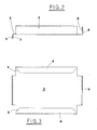
figure 3 illustrates a corresponding plan view; -
figure 4 shows a view of the plan development of a shaped sheet of metal for the creation of the support device in object. - With particular reference to the
figures, 1 refers to the support device for cutting templates, destined to be applied in a machine for cutting tubular-shaped textile products. - The cutting template support device is constituted by a
panel 2 obtained from a sheet ofmetal 10 such as stainless steel, suitably shaped according to the outline shown infig.4 ; themetal sheet 10 is subsequently folded in such a way as to form a sort of drawer. In particular, thepanel 2 has a substantially rectangular shape and along the longitudinal sides has raisedrims 3; thelongitudinal rims 3 have anedge 4 folded towards the centre of thepanel 2, in such a way as to serve as a guide for sliding it onto the press. - The
edges 4 of thelongitudinal rims 3 haverespective bevels 5 at the respective ends. Thebevels 5 cut the outer corners of theedges 4 at an angle of 45°. - Along the transversal sides, on the other hand, the
panel 2 presentsfurther rims same panel 2. - In particular, the
front rim 6 is raised in the same direction as thelongitudinal rims 3, in other words upwards when in an operative set-up on the press, and is destined to act as a handle of the support device. Thefrontal rim 6 usefully presents a crushedfold stretch 8, obtained by folding a marginal portion on to the inner face of thesame rim 6. - The
rear rim 7 is folded downwards, in other words from the opposite side of thepanel 2 to therims rear rim 7 in turn presents a stretch of crushedfold 9, obtained by a marginal portion on to the outer face of thesame rim 7. - It should be pointed out that the
longitudinal rims 3 and thetransversal rims panel 2, as they do not affect the corner area of thepanel 2. Usefully it is foreseen that these corner areas be removed, as shown infig. 3 . - The functioning of the support device for cutting templates is easily understandable from the above description.
- The support device for cutting templates achieves the purpose of creating a considerable reduction in production costs, in particular thanks to considerable material savings and an optimisation of the work processes required.
- This can be obtained essentially thanks to the production of the
bevels 5 at the ends of theportions 13 of themetal sheet 10 destined to form theedge 4 of the longitudinal rims 3 (seefig. 4 ).Such bevels 5 determine a considerable reduction in the material used, preferably stainless steel. - This saving of material is obviously more significant considering the high number of template holders normally used by sector industries and the high frequency with which they must be replaced.
- The creation of the
bevels 5 also has the advantage of considerably reducing the time required for thesheet 10 cutting operation, as the cutting organs, such as lasers, have to cover a shorter perimetral length than that of conventional template holders. - It should be pointed out that the
bevels 5 also have the purpose of eliminating a cutting part from the device's grip area by the operator, so as to reduce the risk of cuts and the like. In addition to reducing production costs and improving the template holder device's functionality, it also contributes to producing the grip handle in a single piece with thepanel 2, by the folding of arelative portion 16 of the metal sheet 10 (see againfig. 4 ). - This brings about an obvious simplification of the production process, requiring only one process against the two required for conventional template holders, in which the grip handle is obtained from a separate piece of metal sheet, which can subsequently be folded and fixed by welding to a corresponding transversal rim.
- The welding of the grip handle also entails the overlapping of the two parts to be joined, which determines further greater consumption of material than the solution in object, in which the handle is produced in a single piece with
panel 2. - Materials adopted for the actual realisation of the invention, as well as their shapes and sizes can be various, depending on the requirements.
Claims (9)
- Support device for cutting templates in a cutting machine, of the type comprising a panel (2) with a substantially rectangular shape, obtained by folding starting from a sheet of metal (10) developed flat following a predetermined shaped outline and presenting along the respective longitudinal sides raised rims (3) that serve as a guide for sliding when said support device is moved into the cutting machine, characterized in that said panel (2) presents a frontal rim (6) made by folding in a single piece with the same panel (2) and destined to function as a handle of the support device.
- The device according to claim 1, characterized in that said frontal rim (6) is raised in the same direction as the two longitudinal rims (3), upwards when set-up for use on said cutting machine.
- The device according to claim 1, characterized in that said frontal rim (6) has a crushed folded stretch (8), obtained by folding a marginal portion on to the inner face of the same rim (6).
- The device according to claim 1, characterized in that said panel (2) has a rear rim (7) folded from the opposite side than the longitudinal rims (3).
- The device according to claim 4, characterized in that said rear rim (7) has a crushed fold stretch (9), obtained by folding a marginal portion on to the external face of the same rim (7).
- The device according to claim 1, characterized in that said longitudinal rims (3) and said frontal rim (6) do not stretch for the entire length of the corresponding sides of said panel (2), said rims (3, 6) not involving the corner areas of the same panel (2).
- The device according to claim 6, characterized in that said corner areas of said panel (2) are removed.
- The device according to claim 1, characterized in that on said metal sheet (10) there are respective bevels (5) used to reduce the perimeter of said shaped outline of the metal sheet (10), in correspondence with the outer corners of opposite portions (13) destined to form said longitudinal rims (3), said longitudinal rims (3) being respectively fitted with an edge (4) folded towards the centre of said panel (2), presenting said bevels (5) at the opposite extremities, in correspondence with said corners.
- The device according to claim 1, characterized in that said bevels (5) cut the outer corners of said edge (4) of the longitudinal rims (3) at an angle of 45°.
Applications Claiming Priority (2)
| Application Number | Priority Date | Filing Date | Title |
|---|---|---|---|
| IT000718A ITBO20020718A1 (en) | 2002-11-14 | 2002-11-14 | SUPPORT DEVICE FOR CUTTING SHAPES. |
| EP03772636A EP1590137B1 (en) | 2002-11-14 | 2003-10-08 | Support device for cutting templates |
Related Parent Applications (2)
| Application Number | Title | Priority Date | Filing Date |
|---|---|---|---|
| EP03772636A Division EP1590137B1 (en) | 2002-11-14 | 2003-10-08 | Support device for cutting templates |
| EP03772636.1 Division | 2003-10-08 |
Publications (3)
| Publication Number | Publication Date |
|---|---|
| EP1905557A2 true EP1905557A2 (en) | 2008-04-02 |
| EP1905557A3 EP1905557A3 (en) | 2009-07-15 |
| EP1905557B1 EP1905557B1 (en) | 2012-04-25 |
Family
ID=32310128
Family Applications (2)
| Application Number | Title | Priority Date | Filing Date |
|---|---|---|---|
| EP07123354A Expired - Lifetime EP1905557B1 (en) | 2002-11-14 | 2003-10-08 | Support device for cutting templates |
| EP03772636A Expired - Lifetime EP1590137B1 (en) | 2002-11-14 | 2003-10-08 | Support device for cutting templates |
Family Applications After (1)
| Application Number | Title | Priority Date | Filing Date |
|---|---|---|---|
| EP03772636A Expired - Lifetime EP1590137B1 (en) | 2002-11-14 | 2003-10-08 | Support device for cutting templates |
Country Status (7)
| Country | Link |
|---|---|
| US (1) | US7533554B2 (en) |
| EP (2) | EP1905557B1 (en) |
| AT (2) | ATE554895T1 (en) |
| DE (1) | DE60322268D1 (en) |
| ES (1) | ES2310248T3 (en) |
| IT (1) | ITBO20020718A1 (en) |
| WO (1) | WO2004043660A1 (en) |
Families Citing this family (2)
| Publication number | Priority date | Publication date | Assignee | Title |
|---|---|---|---|---|
| US8708304B2 (en) * | 2007-11-27 | 2014-04-29 | Bsh Home Appliances Corporation | Appliance base for an appliance |
| US7806024B1 (en) * | 2008-02-20 | 2010-10-05 | Forest Hill Manufacturing, Llc | Method for making shovel |
Family Cites Families (10)
| Publication number | Priority date | Publication date | Assignee | Title |
|---|---|---|---|---|
| US1467787A (en) * | 1921-05-25 | 1923-09-11 | Worthy D Gemmill | Frame and method of making it |
| GB332073A (en) * | 1929-07-27 | 1930-07-17 | T H Prosser And Sons Ltd | Improvements relating to sliding bins of kitchen cabinets and the like |
| GB620552A (en) * | 1947-01-22 | 1949-03-25 | Weldall & Assembly Ltd | Improvements in or relating to drawers |
| CH372546A (en) * | 1962-01-11 | 1963-10-15 | Bobst Fils Sa J | Method of auxiliary fixing of the tool of a platen press in the working position against the upper base and device for implementing this method |
| DE3403323A1 (en) * | 1984-01-31 | 1985-08-01 | Edgar 8120 Weilheim Erdmann | Photographic cutting device |
| JPH0195818A (en) * | 1987-10-07 | 1989-04-13 | Matsushita Electric Works Ltd | Working method for sheet metal box |
| GB2286960A (en) * | 1994-02-25 | 1995-09-06 | Ub Office Systems Co Ltd | Flat pack assembly-type cabinet |
| US6478391B1 (en) * | 1998-06-17 | 2002-11-12 | Sandusky Cabinets, Inc. | Cabinet |
| DE19855127B4 (en) * | 1998-11-30 | 2006-09-21 | Man Roland Druckmaschinen Ag | cover |
| DE19911499C2 (en) * | 1999-03-16 | 2002-06-27 | Koehler Gmbh | Baking tray or the like |
-
2002
- 2002-11-14 IT IT000718A patent/ITBO20020718A1/en unknown
-
2003
- 2003-10-08 US US10/489,981 patent/US7533554B2/en not_active Expired - Fee Related
- 2003-10-08 AT AT07123354T patent/ATE554895T1/en active
- 2003-10-08 DE DE60322268T patent/DE60322268D1/en not_active Expired - Fee Related
- 2003-10-08 ES ES03772636T patent/ES2310248T3/en not_active Expired - Lifetime
- 2003-10-08 WO PCT/IT2003/000603 patent/WO2004043660A1/en not_active Ceased
- 2003-10-08 EP EP07123354A patent/EP1905557B1/en not_active Expired - Lifetime
- 2003-10-08 EP EP03772636A patent/EP1590137B1/en not_active Expired - Lifetime
- 2003-10-08 AT AT03772636T patent/ATE401177T1/en not_active IP Right Cessation
Also Published As
| Publication number | Publication date |
|---|---|
| ATE401177T1 (en) | 2008-08-15 |
| US7533554B2 (en) | 2009-05-19 |
| ITBO20020718A1 (en) | 2004-05-15 |
| EP1590137B1 (en) | 2008-07-16 |
| DE60322268D1 (en) | 2008-08-28 |
| EP1590137A1 (en) | 2005-11-02 |
| EP1905557B1 (en) | 2012-04-25 |
| WO2004043660A1 (en) | 2004-05-27 |
| EP1905557A3 (en) | 2009-07-15 |
| ATE554895T1 (en) | 2012-05-15 |
| ES2310248T3 (en) | 2009-01-01 |
| US20050230595A1 (en) | 2005-10-20 |
Similar Documents
| Publication | Publication Date | Title |
|---|---|---|
| CN209139555U (en) | A kind of molding equipment for refrigerator-freezer door panel bending | |
| US20170274547A1 (en) | Cutting device for cutting relatively rigid web materials such as paper, cardboard, plastic materials or composites | |
| EP1905557B1 (en) | Support device for cutting templates | |
| US2381955A (en) | Envelope machine | |
| US3079846A (en) | Method and apparatus for scoring and slotting carton blanks | |
| DE60001289D1 (en) | Bending and folding tool for a bending press and bending press equipped with this tool | |
| US4060046A (en) | Hand tool | |
| KR840006156A (en) | Combined shear and punch press | |
| CN212653008U (en) | Rolling, bending and slitting machine | |
| CN213259883U (en) | Full-automatic die-cutting machine | |
| CN211362376U (en) | Edge cutting tool | |
| US20060081103A1 (en) | Grid cutting device | |
| CN218798350U (en) | Stainless steel bending device | |
| CN111497328A (en) | Stamping platform is used in carton production | |
| CN219504950U (en) | Automatic induction mechanism of high-precision die cutting machine | |
| US2408815A (en) | Sanding block | |
| CN112643347A (en) | Automatic machining assembly line for stainless steel cutter | |
| US3509756A (en) | Portable flanging tool | |
| CN215966552U (en) | Hydraulic plate shearing machine limiting device | |
| US364262A (en) | Sheet-metal-scroll cutter | |
| CN109909332A (en) | A kind of panel beating system of electric control cabinet production technology section | |
| CN117140076A (en) | Processing equipment of desk steel support | |
| JPS63199032A (en) | Method and device for press forming | |
| JPH02108420A (en) | Bending die | |
| CN213439782U (en) | Rubber cutter |
Legal Events
| Date | Code | Title | Description |
|---|---|---|---|
| PUAI | Public reference made under article 153(3) epc to a published international application that has entered the european phase |
Free format text: ORIGINAL CODE: 0009012 |
|
| AC | Divisional application: reference to earlier application |
Ref document number: 1590137 Country of ref document: EP Kind code of ref document: P |
|
| AK | Designated contracting states |
Kind code of ref document: A2 Designated state(s): AT BE BG CH CY CZ DE DK EE ES FI FR GB GR HU IE IT LI LU MC NL PT RO SE SI SK TR |
|
| PUAL | Search report despatched |
Free format text: ORIGINAL CODE: 0009013 |
|
| AK | Designated contracting states |
Kind code of ref document: A3 Designated state(s): AT BE BG CH CY CZ DE DK EE ES FI FR GB GR HU IE IT LI LU MC NL PT RO SE SI SK TR |
|
| 17P | Request for examination filed |
Effective date: 20100115 |
|
| AKX | Designation fees paid |
Designated state(s): AT BE BG CH CY CZ DE DK EE ES FI FR GB GR HU IE IT LI LU MC NL PT RO SE SI SK TR |
|
| 17Q | First examination report despatched |
Effective date: 20100315 |
|
| GRAP | Despatch of communication of intention to grant a patent |
Free format text: ORIGINAL CODE: EPIDOSNIGR1 |
|
| GRAS | Grant fee paid |
Free format text: ORIGINAL CODE: EPIDOSNIGR3 |
|
| GRAA | (expected) grant |
Free format text: ORIGINAL CODE: 0009210 |
|
| AC | Divisional application: reference to earlier application |
Ref document number: 1590137 Country of ref document: EP Kind code of ref document: P |
|
| AK | Designated contracting states |
Kind code of ref document: B1 Designated state(s): AT BE BG CH CY CZ DE DK EE ES FI FR GB GR HU IE IT LI LU MC NL PT RO SE SI SK TR |
|
| REG | Reference to a national code |
Ref country code: GB Ref legal event code: FG4D |
|
| REG | Reference to a national code |
Ref country code: CH Ref legal event code: EP |
|
| REG | Reference to a national code |
Ref country code: AT Ref legal event code: REF Ref document number: 554895 Country of ref document: AT Kind code of ref document: T Effective date: 20120515 |
|
| REG | Reference to a national code |
Ref country code: IE Ref legal event code: FG4D |
|
| REG | Reference to a national code |
Ref country code: DE Ref legal event code: R096 Ref document number: 60340775 Country of ref document: DE Effective date: 20120614 |
|
| REG | Reference to a national code |
Ref country code: NL Ref legal event code: VDEP Effective date: 20120425 |
|
| REG | Reference to a national code |
Ref country code: AT Ref legal event code: MK05 Ref document number: 554895 Country of ref document: AT Kind code of ref document: T Effective date: 20120425 |
|
| PG25 | Lapsed in a contracting state [announced via postgrant information from national office to epo] |
Ref country code: FI Free format text: LAPSE BECAUSE OF FAILURE TO SUBMIT A TRANSLATION OF THE DESCRIPTION OR TO PAY THE FEE WITHIN THE PRESCRIBED TIME-LIMIT Effective date: 20120425 Ref country code: CY Free format text: LAPSE BECAUSE OF FAILURE TO SUBMIT A TRANSLATION OF THE DESCRIPTION OR TO PAY THE FEE WITHIN THE PRESCRIBED TIME-LIMIT Effective date: 20120425 Ref country code: SE Free format text: LAPSE BECAUSE OF FAILURE TO SUBMIT A TRANSLATION OF THE DESCRIPTION OR TO PAY THE FEE WITHIN THE PRESCRIBED TIME-LIMIT Effective date: 20120425 |
|
| PG25 | Lapsed in a contracting state [announced via postgrant information from national office to epo] |
Ref country code: GR Free format text: LAPSE BECAUSE OF FAILURE TO SUBMIT A TRANSLATION OF THE DESCRIPTION OR TO PAY THE FEE WITHIN THE PRESCRIBED TIME-LIMIT Effective date: 20120726 Ref country code: PT Free format text: LAPSE BECAUSE OF FAILURE TO SUBMIT A TRANSLATION OF THE DESCRIPTION OR TO PAY THE FEE WITHIN THE PRESCRIBED TIME-LIMIT Effective date: 20120827 Ref country code: SI Free format text: LAPSE BECAUSE OF FAILURE TO SUBMIT A TRANSLATION OF THE DESCRIPTION OR TO PAY THE FEE WITHIN THE PRESCRIBED TIME-LIMIT Effective date: 20120425 |
|
| PG25 | Lapsed in a contracting state [announced via postgrant information from national office to epo] |
Ref country code: BE Free format text: LAPSE BECAUSE OF FAILURE TO SUBMIT A TRANSLATION OF THE DESCRIPTION OR TO PAY THE FEE WITHIN THE PRESCRIBED TIME-LIMIT Effective date: 20120425 |
|
| PG25 | Lapsed in a contracting state [announced via postgrant information from national office to epo] |
Ref country code: EE Free format text: LAPSE BECAUSE OF FAILURE TO SUBMIT A TRANSLATION OF THE DESCRIPTION OR TO PAY THE FEE WITHIN THE PRESCRIBED TIME-LIMIT Effective date: 20120425 Ref country code: DK Free format text: LAPSE BECAUSE OF FAILURE TO SUBMIT A TRANSLATION OF THE DESCRIPTION OR TO PAY THE FEE WITHIN THE PRESCRIBED TIME-LIMIT Effective date: 20120425 Ref country code: SK Free format text: LAPSE BECAUSE OF FAILURE TO SUBMIT A TRANSLATION OF THE DESCRIPTION OR TO PAY THE FEE WITHIN THE PRESCRIBED TIME-LIMIT Effective date: 20120425 Ref country code: NL Free format text: LAPSE BECAUSE OF FAILURE TO SUBMIT A TRANSLATION OF THE DESCRIPTION OR TO PAY THE FEE WITHIN THE PRESCRIBED TIME-LIMIT Effective date: 20120425 Ref country code: CZ Free format text: LAPSE BECAUSE OF FAILURE TO SUBMIT A TRANSLATION OF THE DESCRIPTION OR TO PAY THE FEE WITHIN THE PRESCRIBED TIME-LIMIT Effective date: 20120425 Ref country code: RO Free format text: LAPSE BECAUSE OF FAILURE TO SUBMIT A TRANSLATION OF THE DESCRIPTION OR TO PAY THE FEE WITHIN THE PRESCRIBED TIME-LIMIT Effective date: 20120425 Ref country code: AT Free format text: LAPSE BECAUSE OF FAILURE TO SUBMIT A TRANSLATION OF THE DESCRIPTION OR TO PAY THE FEE WITHIN THE PRESCRIBED TIME-LIMIT Effective date: 20120425 |
|
| PLBE | No opposition filed within time limit |
Free format text: ORIGINAL CODE: 0009261 |
|
| STAA | Information on the status of an ep patent application or granted ep patent |
Free format text: STATUS: NO OPPOSITION FILED WITHIN TIME LIMIT |
|
| 26N | No opposition filed |
Effective date: 20130128 |
|
| PG25 | Lapsed in a contracting state [announced via postgrant information from national office to epo] |
Ref country code: ES Free format text: LAPSE BECAUSE OF FAILURE TO SUBMIT A TRANSLATION OF THE DESCRIPTION OR TO PAY THE FEE WITHIN THE PRESCRIBED TIME-LIMIT Effective date: 20120805 |
|
| REG | Reference to a national code |
Ref country code: DE Ref legal event code: R097 Ref document number: 60340775 Country of ref document: DE Effective date: 20130128 |
|
| PG25 | Lapsed in a contracting state [announced via postgrant information from national office to epo] |
Ref country code: MC Free format text: LAPSE BECAUSE OF NON-PAYMENT OF DUE FEES Effective date: 20121031 |
|
| REG | Reference to a national code |
Ref country code: CH Ref legal event code: PL |
|
| GBPC | Gb: european patent ceased through non-payment of renewal fee |
Effective date: 20121008 |
|
| REG | Reference to a national code |
Ref country code: IE Ref legal event code: MM4A |
|
| REG | Reference to a national code |
Ref country code: FR Ref legal event code: ST Effective date: 20130628 |
|
| PG25 | Lapsed in a contracting state [announced via postgrant information from national office to epo] |
Ref country code: GB Free format text: LAPSE BECAUSE OF NON-PAYMENT OF DUE FEES Effective date: 20121008 Ref country code: IE Free format text: LAPSE BECAUSE OF NON-PAYMENT OF DUE FEES Effective date: 20121008 Ref country code: LI Free format text: LAPSE BECAUSE OF NON-PAYMENT OF DUE FEES Effective date: 20121031 Ref country code: BG Free format text: LAPSE BECAUSE OF FAILURE TO SUBMIT A TRANSLATION OF THE DESCRIPTION OR TO PAY THE FEE WITHIN THE PRESCRIBED TIME-LIMIT Effective date: 20120725 Ref country code: DE Free format text: LAPSE BECAUSE OF NON-PAYMENT OF DUE FEES Effective date: 20130501 Ref country code: CH Free format text: LAPSE BECAUSE OF NON-PAYMENT OF DUE FEES Effective date: 20121031 |
|
| REG | Reference to a national code |
Ref country code: DE Ref legal event code: R119 Ref document number: 60340775 Country of ref document: DE Effective date: 20130501 |
|
| PG25 | Lapsed in a contracting state [announced via postgrant information from national office to epo] |
Ref country code: FR Free format text: LAPSE BECAUSE OF NON-PAYMENT OF DUE FEES Effective date: 20121031 |
|
| PG25 | Lapsed in a contracting state [announced via postgrant information from national office to epo] |
Ref country code: TR Free format text: LAPSE BECAUSE OF FAILURE TO SUBMIT A TRANSLATION OF THE DESCRIPTION OR TO PAY THE FEE WITHIN THE PRESCRIBED TIME-LIMIT Effective date: 20120425 |
|
| PG25 | Lapsed in a contracting state [announced via postgrant information from national office to epo] |
Ref country code: LU Free format text: LAPSE BECAUSE OF NON-PAYMENT OF DUE FEES Effective date: 20121008 |
|
| PG25 | Lapsed in a contracting state [announced via postgrant information from national office to epo] |
Ref country code: HU Free format text: LAPSE BECAUSE OF FAILURE TO SUBMIT A TRANSLATION OF THE DESCRIPTION OR TO PAY THE FEE WITHIN THE PRESCRIBED TIME-LIMIT Effective date: 20031008 |
|
| PGFP | Annual fee paid to national office [announced via postgrant information from national office to epo] |
Ref country code: IT Payment date: 20151027 Year of fee payment: 13 |
|
| PG25 | Lapsed in a contracting state [announced via postgrant information from national office to epo] |
Ref country code: IT Free format text: LAPSE BECAUSE OF NON-PAYMENT OF DUE FEES Effective date: 20161008 |