EP1905482A1 - Planung einer Strahlungsbehandlung über vierdimensionale Abbildungsdaten - Google Patents
Planung einer Strahlungsbehandlung über vierdimensionale Abbildungsdaten Download PDFInfo
- Publication number
- EP1905482A1 EP1905482A1 EP07115355A EP07115355A EP1905482A1 EP 1905482 A1 EP1905482 A1 EP 1905482A1 EP 07115355 A EP07115355 A EP 07115355A EP 07115355 A EP07115355 A EP 07115355A EP 1905482 A1 EP1905482 A1 EP 1905482A1
- Authority
- EP
- European Patent Office
- Prior art keywords
- motion
- dimensional
- target region
- dose
- data
- Prior art date
- Legal status (The legal status is an assumption and is not a legal conclusion. Google has not performed a legal analysis and makes no representation as to the accuracy of the status listed.)
- Ceased
Links
Images


Classifications
-
- A—HUMAN NECESSITIES
- A61—MEDICAL OR VETERINARY SCIENCE; HYGIENE
- A61N—ELECTROTHERAPY; MAGNETOTHERAPY; RADIATION THERAPY; ULTRASOUND THERAPY
- A61N5/00—Radiation therapy
- A61N5/10—X-ray therapy; Gamma-ray therapy; Particle-irradiation therapy
- A61N5/103—Treatment planning systems
- A61N5/1031—Treatment planning systems using a specific method of dose optimization
-
- A—HUMAN NECESSITIES
- A61—MEDICAL OR VETERINARY SCIENCE; HYGIENE
- A61N—ELECTROTHERAPY; MAGNETOTHERAPY; RADIATION THERAPY; ULTRASOUND THERAPY
- A61N5/00—Radiation therapy
- A61N5/10—X-ray therapy; Gamma-ray therapy; Particle-irradiation therapy
- A61N5/103—Treatment planning systems
- A61N5/1037—Treatment planning systems taking into account the movement of the target, e.g. 4D-image based planning
-
- A—HUMAN NECESSITIES
- A61—MEDICAL OR VETERINARY SCIENCE; HYGIENE
- A61N—ELECTROTHERAPY; MAGNETOTHERAPY; RADIATION THERAPY; ULTRASOUND THERAPY
- A61N5/00—Radiation therapy
- A61N5/10—X-ray therapy; Gamma-ray therapy; Particle-irradiation therapy
- A61N5/1048—Monitoring, verifying, controlling systems and methods
- A61N5/1049—Monitoring, verifying, controlling systems and methods for verifying the position of the patient with respect to the radiation beam
-
- A—HUMAN NECESSITIES
- A61—MEDICAL OR VETERINARY SCIENCE; HYGIENE
- A61N—ELECTROTHERAPY; MAGNETOTHERAPY; RADIATION THERAPY; ULTRASOUND THERAPY
- A61N5/00—Radiation therapy
- A61N5/10—X-ray therapy; Gamma-ray therapy; Particle-irradiation therapy
- A61N5/1077—Beam delivery systems
- A61N5/1083—Robot arm beam systems
Definitions
- This invention relates to the field of radiation treatment and, in particular, to treatment planning using four-dimensional imaging data.
- Pathological anatomies such as tumors and lesions can be treated with an invasive procedure, such as surgery, which can be harmful and full of risks for the patient.
- a non-invasive method to treat a pathological anatomy e.g., tumor, lesion, vascular malformation, nerve disorder, etc.
- an external radiation source is used to direct a sequence of x-ray beams at a tumor site from multiple angles, with the patient positioned so the tumor is at the center of rotation (isocenter) of the beam. As the angle of the radiation source changes, every beam passes through the tumor site, but passes through a different area of healthy tissue on its way to the tumor. As a result, the cumulative radiation dose at the tumor is high and the average radiation dose to healthy tissue is low.
- radiotherapy refers to a procedure in which radiation is applied to a target region for therapeutic, rather than necrotic, purposes.
- the amount of radiation utilized in radiotherapy treatment sessions is typically about an order of magnitude smaller, as compared to the amount used in a radiosurgery session.
- Radiotherapy is typically characterized by a low dose per treatment (e.g., 100 - 200 centiGray (cGy)), short treatment times (e.g., 10 to 30 minutes per treatment) and hyperfractionation (e.g., 30 to 45 days of treatment).
- cGy centiGray
- short treatment times e.g. 10 to 30 minutes per treatment
- hyperfractionation e.g., 30 to 45 days of treatment.
- One challenge facing the delivery of radiation to treat pathological anatomies is identifying the target region at a particular point in time because the pathological anatomies may move as a function of the patient's breathing or other natural movements.
- radiation treatment it is useful to accurately locate and track the motion of a target region due to respiratory or other patient motions during the treatment.
- respiratory or other patient motions In order to perform radiation treatment in organs near the abdomen, for example, lungs, liver, or pancreas, it is necessary to take into account the fact that these structures move during the patient's respiratory cycle.
- Conventional methods and systems have been developed for performing tracking of an internal target region, while measuring and/or compensating for breathing and/or other motions of the patient.
- a margin around the target region is defined so that the entire volume traversed by the target region during free breathing receives the prescription dose.
- Another conventional method controls the amplitude of the patient's respiration, for example, by using a restraint on the chest, so that tissue movement is reduced.
- a treatment margin is defined, but in this case a smaller treatment volume is used to reflect the reduced amplitude of motion.
- breath holding and respiratory gating to compensate for target region movement during respiration while a patient is receiving conventional radiation treatments.
- Breath holding requires the patient to hold their breath at the same point in each breathing cycle, during which time the tumor is treated while it is presumably stationary.
- a respirometer is often used to measure the tidal volume and ensure the breath is being held at the same location in the breathing cycle during each irradiation moment. This method takes a relatively long time and often requires training the patient to hold their breath in a repeatable manner.
- Respiratory gating involves a process of measuring the patient's respiratory cycle during treatment and then turning the radiation beam on only for a predetermined part of the patient's breathing cycle. Respiratory gating does not directly compensate for motions that result from breathing. Rather, radiation treatment is synchronized to the patient's breathing pattern, limiting the radiation beam delivery to times when the tumor is presumably in a reference position. Respiratory gating may be quicker than the breath holding method, but also may require the patient to have many sessions of training over several days to breathe in the same manner for long periods of time. Conventional respiratory gating also may expose healthy tissue to radiation before or after the tumor passes into the predetermined position.
- the prescription volume can usually be smaller than that using free breathing without gating.
- Another conventional method of dealing with the motion of a target region during radiation treatment involves the image tracking of fiducial markers that are placed in or near the target region.
- the position and motion of the fiducial markers is correlated with the position and motion of the target region so that real-time correction of the position of the treatment beam to follow the motion of the target region may be realized.
- One such radiation treatment system is the CYBERKNIFE ® system developed by Accuray Incorporated of California. By mounting a compact X-band linear accelerator on a robot arm assembly, the CYBERKNIFE® radiation treatment system can perform real-time compensation for respiratory motion.
- a target region and critical structures to be avoided are delineated on a CT scan, or a set of CT slices of a volume of interest (VOI) in the patient.
- a three-dimensional (3D) CT scan is composed of a three-dimensional model of a volume of interest (e.g., pathological anatomy bearing portion of the body) generated from a collection of two-dimensional (2D) CT slices, with each slice representing a different position in space (for example, a different position along the inferior-superior axis of the patient).
- 2D two-dimensional
- sensors measure the amount of radiation absorbed by different tissues.
- an imaging system records x-ray beams from multiple points.
- a computer program is used to measure the differences in x-ray absorption to form cross-sectional images, or "slices" of the head and brain. These slices are called tomograms; hence the name “computed tomography.”
- dose constraints may then be applied by a medical physicist to these target regions and critical structures.
- the medical physicist specifies the minimum dose, and optionally the maximum dose, to the tumor and the maximum dose to other healthy tissues independently.
- the treatment planning software selects a set of treatment beam parameters (e.g., direction, total number of beams and energy of the beams) in order to achieve the specified dose constraints.
- the dose constraints may be altered, tuning structures may be added, and the treatment plan re-optimized until the dose distribution is acceptable.
- the finalized treatment plan is then sent to a treatment delivery system.
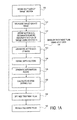
- Figure 1A illustrates a method of radiation treatment planning according one embodiment of the present invention.
- Figure 1B is a conceptual illustration of a 4D CT scan.
- Figure 2 illustrates a graphical output of a treatment planning software displaying a slice of a CT image.
- Figure 3 illustrates an ideal DVH for a pathological anatomy.
- Figure 4 illustrates one embodiment of a desirable DVH for a critical region.
- Figure 5 is a graphical representation of an exemplary dose distribution diagram correlating predicted radiation dose to the relative locations of a target region and a critical structure.
- Figure 6 illustrates one embodiment of a geometry used for dose calculation at the center of a dose volume voxel.
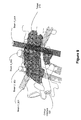
- Figure 7 is a perspective drawing illustrating a workspace of a radiation treatment delivery system including a set of spatial nodes at which to position the radiation source, in accordance with an embodiment of the present invention.
- Figure 8 illustrates two nodes contributing candidate beams for optimization according to one embodiment of the present invention.
- Figure 9 illustrates a three-dimensional perspective view of beam delivery for one embodiment of a radiation treatment process.
- Figure 10 illustrates one embodiment of a treatment system 1700 that may be used to perform radiation treatment in which embodiments of the present invention may be implemented.
- Figure 11 illustrates one embodiment of an image-guided, robotic-based radiation treatment system.
- the methods herein may also be used with other types of radiation treatment systems such as a gantry based radiation delivery system.
- the methods and apparatus are discussed herein in relation to CT imaging only for ease of explanation.
- the method and apparatus discussed herein may also be used to develop treatment plans using other types of four dimensional (4D) medical diagnostic images (anatomical and/or functional), for example, magnetic resonance (MR), ultrasound (US), nuclear medicine (NM) positron emission tomography (PET) and single photon emission computed tomography (SPECT), etc.
- 4D four dimensional
- medical diagnostic images anatomical and/or functional
- MR magnetic resonance
- US ultrasound
- NM nuclear medicine
- PET positron emission tomography
- SPECT single photon emission computed tomography
- target regions may include an anatomical feature(s) of a patient such as a pathological or normal anatomy and may include one or more non-anatomical reference structures.
- a target region need not include an anatomical structure in embodiments outside the field of medical diagnostic imaging and patient treatment.
- Figure 1A illustrates a method of radiation treatment planning according to one embodiment of the present invention.
- the method of the present invention includes obtaining four-dimensional (4D) CT data 110 of the motion, including translation, rotation, and deformation, of the target region and surrounding structures, and developing a treatment plan using the four-dimensional CT data 120.
- the four-dimensional CT scan data may be imported into a treatment planning system or may already reside on a diagnostic CT imaging system that is also used for treatment planning system that was used to perform the diagnostic 4D CT imaging.
- the treatment planning system may be fully compliant with DICOM standards for the distribution and viewing of medical images and the DICOM-RT standard for viewing radiotherapy information overlain on medical images.
- the four dimensions refer to three spatial dimensions and one temporal dimension, as opposed to four spatial dimensions.
- the 4D CT scan data is a collection of three dimensional (spatial) images, with each of the three dimensional images taken at a different point in time in a motion cycle (e.g., during the respiratory cycle, cardiac cycle, artery pulsation, etc. of a patient) with known temporal relationship.
- Figure 1B is a conceptual illustration of a 4D CT scan of a patient's chest region including lungs 60 and a target tumor 50.
- the exemplary 4D CT scan 10 of Figure 1B includes four 3D CTs taken a four time points in the patient's respiratory cycle: CT Time 1, CT Time 2, CT Time 3 and CT Time 4.
- index 0 (time 1) full exhale
- index 100 (time 4) full inhale
- tumor 50 is., for this example, displaced and deformed in the CT image at time 4, full inhale, relative to its positions and shape at full exhale in CT image at time 1.
- the 4D CT scan data may be generated using a 4D CT scanner, for example, a 4D CT scanner produced by General Electric Corp. Alternatively, other 4D CT scanners may be used.
- a 4D CT scanner includes a device, such as a spirometer, strain gauge, optical tracker, etc., that is configured to take instantaneous measurements of the patient's position in the respiratory cycle. When a slice is acquired, the current respiratory measurement position is recorded. This measurement is used to place the CT slice in one of the 3D CT scans with the index closest to the given measurement of the respiratory cycle.
- the 4D CT scan data may be acquired in a single motion cycle, or may be acquired over multiple motion cycles.
- two or more conventional 3D CT images may be acquired during breath hold at different points in the breathing cycle (e.g., at end inspiration and end expiration.
- the term 4D CT scan data is used herein to mean a set of two or more 3D images that represent different time points in a motion cycle regardless of the method of acquiring the scan data.
- the target region is delineated on a CT image, for example, as illustrated in Figure 2 as will be discussed in more detail below.
- one of the 4D CT images may be used for delineation of the target region and critical structures.
- delineation may be performed using a standard CT image acquired with breath hold (i.e., a patient holding their breath).
- delineation may be performed on an image of a different modality, for example, using magnetic resonance imaging (MRI.)
- MRI magnetic resonance imaging
- a motion model is defined so that the movement of target region and surrounding structures within the treatment region is known, step 122.
- the model may be defined, for example, using non-rigid registration techniques. Non-rigid registration techniques are well known in the art; accordingly, a more detailed discussion is not provided.
- a dose distribution is then calculated using the motion model, step 126.
- the motion model together with a weighting (as discussed in further detail below) according to the relative amount of time spent at each point in the motion cycle, is applied to give a dose estimate taking motion (e.g., due to respiration) into account.
- a view of the treatment dose that takes into account motion movement during treatment may be obtained.
- the treating physician or physicist may then use this dose information to change the treatment margins and/or re-optimize the treatment plan, step 130, if desired.
- the treatment plan may also be reviewed after optimization to view effects of the target region motion on the dose distribution, step 140. Further details of embodiments of the method steps of Figure 1A are provided below.
- FIG 2 is a conceptual illustration of a graphical output of a treatment planning system displaying a slice of a CT image in which delineation may be performed.
- the illustration of the CT image 200 includes a target (e.g., pathological anatomy such as a tumor, lesion, vascular malformation, etc.) 210 that is targeted for treatment, and well as a critical region 220 that is positioned near the target region.
- the treatment planning software enables the generation of a critical region contour 225 around the critical region 220 and a target region contour 215 around the target region 210.
- a user manually delineates points (e.g., some of the dots on the contour lines of Figure 2) on the display that is used by the treatment planning software to generate the corresponding contours.
- the treatment planning software Based on specified minimum dose to the target region 210 and the maximum dose to the critical region 220, the treatment planning software generates the dose isocontour 230 for the target region 210.
- the dose isocontour 230 represents a given dose percentage (e.g., 60%, 70%, 80%, etc.) of a specified prescription dose for the target region 210.
- the dose isocontour 230 should perfectly match the contour of the target region 210.
- the dose isocontour 230 generated by the treatment planning software is not optimal, and can include portions of the critical region 220, as illustrated in Figure 2.
- Homogeneity is the uniformity of the radiation dose over the volume of the target region characterized by a dose volume histogram (DVH).
- An ideal DVH 300 for the target region 210 would be a rectangular function as illustrated in Figure 3, where the dose is 100 percent of the prescribed dose over the volume of the target region 210. In an ideal case, the dose would also be zero elsewhere.
- a desirable DVH 400 for a critical region 220 would have the profile illustrated in Figure 4, where the volume of the critical structures receives as little of the prescribed dose as possible.
- Conformality is the degree to which the radiation dose matches (conforms to) the shape and extent of the target region (e.g., tumor) in order to avoid damage to critical adjacent structures.
- CI conformality index
- a clinician identifies a dose isocontour for a corresponding VOI for application of a treatment dose (e.g., 3000 cGy).
- FIG. 5 illustrates one embodiment of a user interface for treatment planning system.
- the user may define a minimum dose constraint for the target region 210 and a maximum dose constraint for a critical region 220.
- a minimum dose constraint of 2400 cGy is set for the target region and a maximum dose constraint of 1200 cGy is set for the right eye critical region shown in box 530 Figure 5.
- Near the right side of the user interface of Figure 5 are a target volume DVH 540 and a critical volume DVH 550.
- the user interface 500 may also display beam statistics in box 555, for example, the total MU 560 and number of beams 570, the minimum non-zero MU of all currently existing beams and the maximum MU.
- a treatment plan may be developed and optimized by enabling a planning algorithm to select a set of treatment beam parameters (e.g., direction, total number of beams and energy of the beams) to best satisfy the dose constraints.
- the user interface 500 may also display some of these beam statistics, box 555, for example, the total MU 560 and number of beams 570, the minimum non-zero MU of all currently existing beams and the maximum MU.
- Figure 6 illustrates one embodiment of a geometry used for dose calculation at the center of a dose volume voxel.
- the center of a voxel is represented as a position "p.”
- the closest point to p on the beam axis is represented as "c.”
- the point of origin of the beam is represented as "n.”
- the distance from p to c is "d.”
- Figure 6 is an illustration of a 2D dose calculation geometry.
- a 3D geometry may be constructed, for example, by using a 3D grid instead of the 2D grid shown in Figure 6.
- Dose calculation may be performed using a mass data storage model to calculate the radiation dose to tissue from the treatment beams from the various different parameters that are run through by the planning algorithm.
- an array of effective depth is constructed along each beam axis, using the CT number of the tissues the beam passes through, together with a model relating the CT number to electron density.
- the following simplifying assumptions may be made: (1) all energy is deposited locally, i.e., charged particle equilibrium is assumed; and (2) the effective depth of tissue between the collimator and the calculation point p is the same as the effective depth between the collimator of the radiation beam source and the corresponding point c on the beam axis.
- Dose may be discretized by dividing the dose calculation volume into volume pixels, or voxels. For each voxel, the dose with respect to each treatment beam is calculated and added. The equation for radiation dose for a single beam is:
- D(p) is the radiation dose in cGy delivered by the beam to point p
- MU is the number of monitor units of the beam (linearly related to the amount of time for which the beam is enabled)
- OP is the output factor
- TMR is the tissue maximum ratio
- OCR is the off-axis correction ratio
- s is the field size
- d is the distance of p from the beam central axis
- e(c) is the effective depth of tissue between the collimator and c.
- a dose mask is a representation where each beam has a mask: the mask elements each represent a distinct spatial position and the amount of dose per MU contributed by the beam at that position.
- an inverse planning algorithm may be used that starts with approximately 1200 candidate beams.
- This set of beams may have on the order of 100 distinct points of origins, which may be referred to as nodes, which are discrete positions traversed by the radiation source that generates the beam during treatment.
- these nodes make a shape somewhat like a hemispherical shell 730 surrounding a portion of the patient 110 (e.g., the head) as illustrated in Figure 7.
- the nodes may form other geometries (e.g., elliptical).
- equation (1) is just one example of a dose calculation methodology.
- Other methodologies for calculating the dose delivered by a radiation beam to a single point for example, superposition convolution and Monte Carlo simulation, are well known in the art and may alternatively be applied to derive D(p).
- Spatial nodes 735 are represented by the "+" symbol (only a few are illustrated) in Figure 7 and indicate positions where radiation source 705 is allowed to stop and delivery a dose of radiation to the VOI within the patient.
- a robotic arm 725 may be used to move radiation source 705 to each and every spatial node 735 following a predefined path.
- other types of mechanisms such as a gantry may be utilized to move radiation source 705.
- radiation source 705 may still visit that particular spatial node 735. It should be appreciated that the complete node set may include more or fewer spatial nodes 735 than is illustrated or discussed.
- Each node 735 may contribute multiple beam orientations to the treatment planning set of beams.
- Figure 8 illustrates two nodes 810 and 820 of a node set, with each of the nodes contributing an exemplary 12 candidate beams for optimization. Only the central axis of each of a beam 830 is shown in Figure 8. However, each beam will contribute dose in a three dimensional (e.g., conical) region centered around its axis.
- the candidate beams at nodes 810 and 820 are representative of beam delivery based on conformal planning, in which the radiation beams pass through or terminate at various points within the target region. In conformal planning, some radiation beams may or may not intersect or converge at a common point in three-dimensional space.
- the delivered radiation beams may be non-isocentric in that the beams do not necessarily converge on a single point, or isocenter. This may be more readily seen in the three-dimensional perspective view of Figure 9, where the exemplary beams 901, 902, 903 and 904 intersect with target region 210, and possibly each other, but do not converge on a single point.
- the beam geometry is created by choosing 12 random points either on the periphery or internal to the treatment target region.
- the results of the computation described above in equation (1) are stored as a linked list composed of elements giving location (index of the dose volume voxel) and dose per unit time at that location.
- a CT image is designated to be a reference image.
- a position in the reference CT image is denoted as x 0 .
- N additional CT images making up the 4D CT set.
- a set of vectors ⁇ 1 (x 0 ) ... ⁇ N (x 0 ) ⁇ is derived so that x 0 + ⁇ i represents the same anatomical point in image i as x 0 in the reference image.
- a set of third-order B-splines and an intensity-based cost function is used to find a set of deformation fields ⁇ i (x).
- An exemplary intensity-based cost function that may be used is described in J.B. West, C.R.
- a weight, W i ; ⁇ i W i 1, is assigned to each image, step 123.
- the W i model is the relative time spent by the target region in each part of the motion cycle.
- the motion cycle refers to any movement, rotation, and/or deformation of the target region and nearby structures that is periodic in nature, for example that caused by respiration. More radiation dose will be absorbed during the parts of the cycle that take up the most time.
- the W i may be calculated, for example, using a standard table or formula describing the relative amount of time spent by a typical person in different phases of the respiratory cycle.
- the W i may be derived from a priori breathing data measured for the particular patient. Similar where the motion is due to other factors (e.g., cardiac motion), W i may be derived from corresponding motion (e.g., cardiac) data measured for the particular patient.
- the images making up the 4D CT set are separated into equal time intervals, rather than equal motion intervals.
- W i 1/ N is used for all i , where N is the number of images making up the 4D CT set.
- the W i may be proportional to the size of the time interval for each image i, and normalized so that the sum of the W i is equal to 1.
- an effective depth vector V i along the central axis of the beam is derived for each image i, step 124.
- V i When deriving V i , note may be taken of the movement of the beam to follow a fiducial centroid, or other landmark, if there is a dynamic target tracking method to be used during treatment.
- Dynamic target tracking is known in the art; accordingly, a more detailed description is not provided. Dynamic target tracking techniques are discussed, for example, in U.S. Patent 5,207,223 . Alternatively, other dynamic tracking techniques may be used.
- both the source and target coordinates of the beam may be incremented by the offset of the object being tracked, to mimic the effect of dynamic tracking during treatment.
- three steps are required before a 4D dose distribution is calculated: define the depth vectors V i according to predicted movements of the beams during treatment (for example, if the dynamic target tracking method is to be used), step 124; define the W i which describe the relative amounts of time the patient is predicted to spend in each part of the respiratory cycle, step 123, and; generate the deformation fields ⁇ i, , step 125, for example, by using a non-rigid registration technique.
- steps 123, 124 and 125 need not be performed in the order illustrated in Figure 1A.
- a 4D dose calculation may be performed, step 126, that takes respiratory motion into account as follows:
- D i (p) is the dose, in cGy, given by the beam to point p during part i of the breathing cycle.
- deformation is taken account of in two ways. In all places that effective depth e is used, we replace it with the quantity e i , i.e., the effective depth looked up from central axis vector V i . This takes into account the fact that the amount and types of tissue traversed by the beam may change as the body deforms, and the beam is moved to track the target, thus leading to a variation of the attenuation effect at the target point. The more dominant effect in most cases, however, is the fact that the off-axis correction ratio (OCR) has been modified to take into account the amount of deformation.
- OCR off-axis correction ratio
- a point that is close to the beam axis at one point in the respiratory cycle may move further away at another point in the cycle.
- the amount of movement is significant with respect to the cross section of the beam (e.g., conical beams that have a diameter of between 5 mm and 60 mm at 800 mm from the radiation source)
- the radiation dose may be substantially changed.
- this second effect is much more significant in terms of modeling the change of radiation dose.
- the coordinate system in which the ⁇ i are represented may be easily changed.
- the dose calculation is all referred to a reference coordinate system: that of the CT image designated to be the reference image.
- a reference coordinate system that of the CT image designated to be the reference image.
- an optimization step 130 may be performed after generation of the motion model.
- the optimization step takes into account the target region motion (e.g., deformation) and change in dose distribution during the motion cycle (e.g., respiration).
- the optimization process determines a set of treatment beam parameters (a set of beams, the position and orientation of each beam, the field size and optionally shape of each beam, and the relative or absolute quantity of radiation of each beam) such that the dose distribution produced by this set of treatment beam parameters optimizes a set of user-specified dose constraints (minimum and optionally maximum dose to the target region and the maximum dose to different healthy tissues).
- the field size and shape of each beam, and the quantity of radiation of each beam may vary with the time point in the motion cycle.
- optimization algorithms such as an iterative algorithm and non-iterative algorithm may be used.
- an iterative algorithm or non-iterative e.g., Simplex algorithm
- a set of dose masks giving discretized estimates of dose/MU for each beam may be used as input.
- a set of dose constraints input by the user to determine the desirable dose distribution for that planning task may also be provided to the treatment planning algorithm.
- the optimization step 130 is not affected by whether or not a motion model was used to build the dose masks.
- the resulting dose distribution will automatically have been optimized using the known characteristics of the target region motion and beam motion during the motion cycle.
- optimization algorithms such as an iterative algorithm and Simplex algorithm are known in the art; accordingly, a more detail discussion is not provided.
- the method of the present invention is discussed above in regards to inverse, or conformal, planning, part or all of the treatment plan may be developed using forward planning techniques.
- forward planning the user of the treatment planning system (e.g., medical physicist) chooses the directions of the beams and the intensity of the beams and then the treatment planning algorithm calculates and displays the resulting dose distribution. More specifically, the user may specify particular directions and intensities for the radiation beams to be generated by the radiation treatment delivery system, choosing from a subset of available beams determined by constraints on the delivery system itself. The user may "guess" or assign, based on their experience, values to beam directions and intensities, or weights. The treatment planning system then calculates the resulting dose distribution.
- the user may manually change their selection of beams in an attempt to improve the dose distribution.
- the feedback given to the user is the dose profile corresponding to the current plan where beams may be removed, changed or added until the dose profile is deemed acceptable.
- the user may adjust the values of the treatment parameters.
- the system re-calculates a new resulting dose distribution. This process may be repeated, until the user is satisfied by the resulting dose distribution, as compared to a desired distribution.
- a review step 140 of Figure 1A is performed after optimization, in order to view the effects of motion (e.g., deformation) on the dose distribution of a treatment plan optimized using a single image.
- a motion (e.g., deformation) model using a 4D CT set is constructed and the beam dose masks using the beam geometry and weighting (MU per beam) from the original plan is recalculated.
- the DVHs and dose isocontours for the original plan and its 4D recalculated version may be viewed side-by-side, so that a physician or physicist may make a determination about whether the motion will have any clinical effect on the outcome of the plan delivery.
- the next step may then be to return to the planning step and re-optimize using the updated dose information.
- FIG 10 illustrates one embodiment of a treatment system 1700 that may be used to perform radiation treatment in which embodiments of the present invention may be implemented.
- the depicted treatment system 500 includes a diagnostic imaging system 2000, a treatment planning system 3000, and a treatment delivery system 4000.
- Diagnostic imaging system 2000 is representative of a system capable of producing medical diagnostic images of a VOI that may be used for subsequent diagnosis, treatment planning and/or treatment delivery.
- diagnostic imaging system 2000 may be a computed tomography (CT) system, a magnetic resonance imaging (MRI) system, a positron emission tomography (PET) system, an ultrasound system or the like.
- CT computed tomography
- MRI magnetic resonance imaging
- PET positron emission tomography
- ultrasound system or the like.
- diagnostic imaging system 2000 is discussed at times in relation to a CT x-ray imaging modality. However, other imaging modalities such as those above may also be used.
- Diagnostic imaging system 2000 includes an imaging source 2010 to generate an imaging beam (e.g., x-rays, ultrasonic waves, radio frequency waves, etc.) and an imaging detector 2020 to detect and receive the beam generated by imaging source 2010, or a secondary beam or emission stimulated by the beam from the imaging source (e.g., in an MRI or PET scan).
- imaging system 2000 represents a 4D CT scanner as discussed above.
- diagnostic imaging system 2000 may include two or more diagnostic X-ray sources and two or more corresponding imaging detectors.
- two x-ray sources may be disposed around a patient to be imaged, fixed at an angular separation from each other (e.g., 90 degrees, 45 degrees, etc.) and aimed through the patient toward (an) imaging detector(s) which may be diametrically opposed to the x-ray sources.
- an imaging detector(s) which may be diametrically opposed to the x-ray sources.
- a single large imaging detector, or multiple imaging detectors, may also be used that would be illuminated by each x-ray imaging source.
- other numbers and configurations of imaging sources and imaging detectors may be used.
- the imaging source 2010 and the imaging detector 2020 are coupled to a digital processing system 2030 to control the imaging operation and process image data.
- Diagnostic imaging system 2000 includes a bus or other means 2035 for transferring data and commands among digital processing system 2030, imaging source 2010 and imaging detector 2020.
- Digital processing system 2030 may include one or more general-purpose processors (e.g., a microprocessor), special purpose processor such as a digital signal processor (DSP) or other type of device such as a controller or field programmable gate array (FPGA).
- Digital processing system 2030 may also include other components (not shown) such as memory, storage devices, network adapters and the like.
- Digital processing system 2030 may be configured to generate digital diagnostic images in a standard format, such as the DICOM (Digital Imaging and Communications in Medicine) format, for example.
- DICOM Digital Imaging and Communications in Medicine
- digital processing system 2030 may generate other standard or non-standard digital image formats.
- Digital processing system 2030 may transmit diagnostic image files (e.g., the aforementioned DICOM formatted files) to treatment planning system 3000 over a data link 1500, which may be, for example, a direct link, a local area network (LAN) link or a wide area network (WAN) link such as the Internet.
- a data link 1500 which may be, for example, a direct link, a local area network (LAN) link or a wide area network (WAN) link such as the Internet.
- LAN local area network
- WAN wide area network
- the information transferred between systems may either be pulled or pushed across the communication medium connecting the systems, such as in a remote diagnosis or treatment planning configuration.
- a user may utilize embodiments of the present invention to diagnose or treatment plan despite the existence of a physical separation between the system user and the patient.
- Treatment planning system 3000 includes a processing device 3010 to receive and process image data such as the 4D CT data discussed above.
- Processing device 3010 may represent one or more general-purpose processors (e.g., a microprocessor), special purpose processor such as a digital signal processor (DSP) or other type of device such as a controller or field programmable gate array (FPGA).
- DSP digital signal processor
- FPGA field programmable gate array
- Processing device 3010 may be configured to execute instructions for performing the operations of the methods discussed herein that, for example, may be loaded in processing device 3010 from storage 3030 and/or system memory 3020.
- Treatment planning system 3000 may also include system memory 3020 that may include a random access memory (RAM), or other dynamic storage devices, coupled to processing device 3010 by bus 3055, for storing information and instructions to be executed by processing device 3010.
- System memory 3020 also may be used for storing temporary variables or other intermediate information during execution of instructions by processing device 3010.
- System memory 3020 may also include a read only memory (ROM) and/or other static storage device coupled to bus 3055 for storing static information and instructions for processing device 3010.
- ROM read only memory
- Treatment planning system 3000 may also include storage device 3030, representing one or more storage devices (e.g., a magnetic disk drive or optical disk drive) coupled to bus 3055 for storing information and data, for example, the 4D CT data discussed above.
- Storage device 3030 may also be used for storing instructions for performing the treatment planning methods discussed herein.
- Processing device 3010 may also be coupled to a display device 3040, such as a cathode ray tube (CRT) or liquid crystal display (LCD), for displaying information (e.g., a two-dimensional or three-dimensional representation of the VOI) to the user.
- a display device 3040 such as a cathode ray tube (CRT) or liquid crystal display (LCD)
- An input device 3050 such as a keyboard, may be coupled to processing device 3010 for communicating information and/or command selections to processing device 3010.
- One or more other user input devices e.g., a mouse, a trackball or cursor direction keys
- treatment planning system 3000 represents only one example of a treatment planning system, which may have many different configurations and architectures, which may include more components or fewer components than treatment planning system 3000 and which may be employed with the present invention. For example, some systems often have multiple buses, such as a peripheral bus, a dedicated cache bus, etc.
- the treatment planning system 3000 may also include MIRIT (Medical Image Review and Import Tool) to support DICOM import (so images can be fused and target regions delineated on different systems and then imported into the treatment planning system for planning and dose calculations), expanded image fusion capabilities that allow the user to treatment plan and view dose distributions on any one of various imaging modalities (e.g., MRI, CT, PET, etc.).
- MIRIT Medical Image Review and Import Tool
- DICOM import so images can be fused and target regions delineated on different systems and then imported into the treatment planning system for planning and dose calculations
- expanded image fusion capabilities that allow the user to treatment plan and view dose distributions on any one of various imaging modalities (e.g
- Treatment planning system 3000 may share its database (e.g., data stored in storage device 3030) with a treatment delivery system, such as treatment delivery system 4000, so that it may not be necessary to export from the treatment planning system prior to treatment delivery.
- Treatment planning system 3000 may be linked to treatment delivery system 4000 via a data link 2500, which may be a direct link, a LAN link or a WAN link as discussed above with respect to data link 1500.
- data links 1500 and 2500 are implemented as LAN or WAN connections
- any of diagnostic imaging system 2000, treatment planning system 3000 and/or treatment delivery system 4000 may be in decentralized locations such that the systems may be physically remote from each other.
- any of diagnostic imaging system 2000, treatment planning system 3000 and/or treatment delivery system 4000 may be integrated with each other in one or more systems.
- Treatment delivery system 4000 includes a therapeutic and/or surgical radiation source 4010 to administer a prescribed radiation dose to a target volume in conformance with a treatment plan.
- Treatment delivery system 4000 may also include an imaging system 4020 to capture intra-treatment images of a patient volume (including the target volume) for registration or correlation with the diagnostic images described above in order to position the patient with respect to the radiation source.
- Treatment delivery system 4000 may also include a digital processing system 4030 to control radiation source 4010, imaging system 4020, and a patient support device such as a treatment couch 4040.
- Digital processing system 4030 may include one or more general-purpose processors (e.g., a microprocessor), special purpose processor such as a digital signal processor (DSP) or other type of device such as a controller or field programmable gate array (FPGA). Digital processing system 4030 may also include other components (not shown) such as memory, storage devices, network adapters and the like. Digital processing system 4030 may be coupled to radiation source 4010, imaging system 4020 and treatment couch 4040 by a bus 4045 or other type of control and communication interface.
- general-purpose processors e.g., a microprocessor
- DSP digital signal processor
- FPGA field programmable gate array
- Digital processing system 4030 may also include other components (not shown) such as memory, storage devices, network adapters and the like.
- Digital processing system 4030 may be coupled to radiation source 4010, imaging system 4020 and treatment couch 4040 by a bus 4045 or other type of control and communication interface.
- treatment system 1700 is only representative of an exemplary system. Other embodiments of the system 1700 may have many different configurations and architectures and may include fewer or more components.
- treatment delivery system 4000 may be an image-guided, robotic-based radiation treatment system (e.g., for performing radiosurgery) such as the CYBERKNIFE® system developed by Accuray, Incorporated of California.
- radiation source 4010 may be represented by a linear accelerator (LINAC) 4051 mounted on the end of a robotic arm 4052 having multiple (e.g., 5 or more) degrees of freedom in order to position the LINAC 4051 to irradiate a pathological anatomy (target region or volume) with beams delivered from many angles in an operating volume (e.g., a sphere) around the patient.
- LINAC linear accelerator
- Treatment may involve beam paths with a single isocenter (point of convergence), multiple isocenters, or with a non-isocentric approach (i.e., the beams need only intersect with the pathological target volume and do not necessarily converge on a single point, or isocenter, within the target region as illustrated in Figure 9). Treatment can be delivered in either a single session (mono-fraction) or in a small number of sessions as determined during treatment planning.
- radiation beams may be delivered according to the treatment plan without fixing the patient to a rigid, external frame to register the intra-operative position of the target volume with the position of the target volume during the pre-operative treatment planning phase.
- imaging system 4020 may be represented by X-ray sources 4053 and 4054 and X-ray image detectors (imagers) 4056 and 4057.
- two x-ray sources 4053 and 4054 may be nominally aligned to project imaging x-ray beams through a patient from two different angular positions (e.g., separated by 90 degrees, 45 degrees, etc.) and aimed through the patient on treatment couch 4050 toward respective detectors 4056 and 4057.
- a single large imager can be used that would be illuminated by each x-ray imaging source.
- other numbers and configurations of imaging sources and imagers may be used.
- Digital processing system 4030 may implement algorithms to register images obtained from imaging system 4020 with pre-operative treatment planning images in order to align the patient on the treatment couch 4050 within the treatment delivery system 4000, and to precisely position the radiation source with respect to the target volume.
- the treatment couch 4050 may be coupled to another robotic arm (not illustrated) having multiple (e.g., 5 or more) degrees of freedom.
- the couch arm may have five rotational degrees of freedom and one substantially vertical, linear degree of freedom.
- the couch arm may have six rotational degrees of freedom and one substantially vertical, linear degree of freedom or at least four rotational degrees of freedom.
- the couch arm may be vertically mounted to a column or wall, or horizontally mounted to pedestal, floor, or ceiling.
- the treatment couch 4050 may be a component of another mechanical mechanism, such as the Axum® treatment couch developed by Accuray Incorporated of California, or be another type of conventional treatment table known to those of ordinary skill in the art.
- treatment delivery system 4000 may be another type of treatment delivery system, for example, a gantry based (isocentric) intensity modulated radiotherapy (IMRT) system.
- a radiation source e.g., a LINAC
- LINAC a radiation source
- Radiation is then delivered from several positions on the circular plane of rotation.
- the shape of the radiation beam is defined by a multi-leaf collimator that allows portions of the beam to be blocked, so that the remaining beam incident on the patient has a pre-defined shape.
- the resulting system generates arbitrarily shaped radiation beams that intersect each other at the isocenter to deliver a dose distribution to the target region.
- the optimization algorithm selects subsets of the main beam and determines the amount of time that the patient should be exposed to each subset, so that the prescribed dose constraints are best met.
- the gantry based system may have a gimbaled radiation source head assembly.
- treatment may refer generally to the effectuation of an operation controlled by the treatment planning system, such as the application of a beam (e.g., radiation, acoustic, etc.) and "target” may refer to a non-anatomical object or area.
- a beam e.g., radiation, acoustic, etc.
- target may refer to a non-anatomical object or area.
- Embodiments of the present invention include various operations, which are described herein. These operations may be performed by hardware components, software, firmware, or a combination thereof. Any of the signals provided over various buses described herein may be time multiplexed with other signals and provided over one or more common buses. Additionally, the interconnection between circuit components or blocks may be shown as buses or as single signal lines. Each of the buses may alternatively be one or more single signal lines and each of the single signal lines may alternatively be buses.
- Certain embodiments may be implemented as a computer program product that may include instructions stored on a machine-readable medium. These instructions may be used to program a general-purpose or special-purpose processor to perform the described operations.
- a machine-readable medium includes any mechanism for storing or transmitting information in a form (e.g., software, processing application) readable by a machine (e.g., a computer).
- the machine-readable medium may include, but is not limited to, magnetic storage medium (e.g., floppy diskette); optical storage medium (e.g., CD-ROM); magneto-optical storage medium; read-only memory (ROM); random-access memory (RAM); erasable programmable memory (e.g., EPROM and EEPROM); flash memory; electrical, optical, acoustical, or other form of propagated signal (e.g., carrier waves, infrared signals, digital signals, etc.); or another type of medium suitable for storing electronic instructions.
- magnetic storage medium e.g., floppy diskette
- optical storage medium e.g., CD-ROM
- magneto-optical storage medium e.g., magneto-optical storage medium
- ROM read-only memory
- RAM random-access memory
- EPROM and EEPROM erasable programmable memory
- flash memory electrical, optical, acoustical, or other form of propagated signal (e.g., carrier waves, in
- some embodiments may be practiced in distributed computing environments where the machine-readable medium is stored on and/or executed by more than one computer system.
- the information transferred between computer systems may either be pulled or pushed across the communication medium connecting the computer systems such as in a remote diagnosis or monitoring system.
- remote diagnosis or monitoring a user may diagnose or monitor a patient despite the existence of a physical separation between the user and the patient.
- the treatment delivery system may be remote from the treatment planning system.
Applications Claiming Priority (1)
| Application Number | Priority Date | Filing Date | Title |
|---|---|---|---|
| US11/540,327 US10279196B2 (en) | 2006-09-28 | 2006-09-28 | Radiation treatment planning using four-dimensional imaging data |
Publications (1)
| Publication Number | Publication Date |
|---|---|
| EP1905482A1 true EP1905482A1 (de) | 2008-04-02 |
Family
ID=38740185
Family Applications (1)
| Application Number | Title | Priority Date | Filing Date |
|---|---|---|---|
| EP07115355A Ceased EP1905482A1 (de) | 2006-09-28 | 2007-08-30 | Planung einer Strahlungsbehandlung über vierdimensionale Abbildungsdaten |
Country Status (4)
| Country | Link |
|---|---|
| US (2) | US10279196B2 (de) |
| EP (1) | EP1905482A1 (de) |
| JP (1) | JP5411418B2 (de) |
| CN (1) | CN101172053A (de) |
Cited By (6)
| Publication number | Priority date | Publication date | Assignee | Title |
|---|---|---|---|---|
| WO2011128350A1 (en) * | 2010-04-13 | 2011-10-20 | Mirada Medical Limited | Method for estimating radiation exposure of a patient and radiation exposure monitoring system therefor |
| WO2012123894A1 (en) * | 2011-03-15 | 2012-09-20 | Koninklijke Philips Electronics N.V. | Studying dosimetric impact of motion to generate adaptive patient-specific margins in ebrt planning |
| EP2692392A1 (de) * | 2012-07-30 | 2014-02-05 | Hitachi Ltd. | Behandlungsplanungssystem |
| WO2016070938A1 (en) * | 2014-11-07 | 2016-05-12 | Raysearch Laboratories Ab | Robust radiotherapy treatment plan generation |
| EP3546022A1 (de) * | 2018-03-29 | 2019-10-02 | Hitachi, Ltd. | Partikeltherapieplanungsvorrichtung, partikeltherapiesystem und dosisverteilungsberechnungsprogramm |
| EP3586920A1 (de) * | 2018-06-29 | 2020-01-01 | RaySearch Laboratories AB | System und verfahren zur bestrahlungsbehandlungsplanung |
Families Citing this family (68)
| Publication number | Priority date | Publication date | Assignee | Title |
|---|---|---|---|---|
| US10279196B2 (en) * | 2006-09-28 | 2019-05-07 | Accuray Incorporated | Radiation treatment planning using four-dimensional imaging data |
| US8849373B2 (en) * | 2007-05-11 | 2014-09-30 | Stanford University | Method and apparatus for real-time 3D target position estimation by combining single x-ray imaging and external respiratory signals |
| DE102007030962A1 (de) * | 2007-07-04 | 2009-01-15 | Siemens Ag | Verfahren zur Gewinnung von Messdaten |
| US7835493B2 (en) * | 2007-08-06 | 2010-11-16 | Stanford University | Method and system for four dimensional intensity modulated radiation therapy for motion compensated treatments |
| US7682077B2 (en) * | 2008-06-12 | 2010-03-23 | General Electric Company | Method and apparatus for driving a mobile imaging system |
| DE102008044901A1 (de) * | 2008-08-29 | 2010-03-04 | Siemens Aktiengesellschaft | Verfahren und Vorrichtung zur Auswahl eines Bestrahlungsplans sowie Bestrahlungsanlage |
| US8180020B2 (en) * | 2008-10-23 | 2012-05-15 | Accuray Incorporated | Sequential optimizations for treatment planning |
| JP2012510641A (ja) * | 2008-12-01 | 2012-05-10 | ライフ イメージ インク. | 医用画像ビューア |
| JP4418888B1 (ja) | 2009-03-25 | 2010-02-24 | 株式会社アキュセラ | X線治療装置 |
| EP2414042A4 (de) | 2009-03-31 | 2013-01-30 | Matthew R Witten | System und verfahren zur planung einer strahlungstherapeutischen behandlung mithilfe eines algorithmus für memetische optimierung |
| US9165385B2 (en) * | 2009-06-18 | 2015-10-20 | Koninklijke Philips N.V. | Imaging procedure planning |
| US9146289B2 (en) * | 2009-12-23 | 2015-09-29 | General Electric Company | Targeted thermal treatment of human tissue through respiratory cycles using ARMA modeling |
| US8396270B2 (en) * | 2010-02-16 | 2013-03-12 | The Board Of Trustees Of The Leland Stanford Junior University | Method to estimate 3D abdominal and thoracic tumor position to submillimeter accuracy using sequential x-ray imaging and respiratory monitoring |
| EP3722836A1 (de) * | 2010-06-22 | 2020-10-14 | Varian Medical Systems International AG | System und verfahren zur messung und zur änderung einer gemessenen strahlendosis |
| US10076303B2 (en) | 2010-09-07 | 2018-09-18 | Insightec, Ltd. | Motion compensation for non-invasive treatment therapies |
| US8824630B2 (en) * | 2010-10-29 | 2014-09-02 | Accuray Incorporated | Method and apparatus for treating a target's partial motion range |
| RU2604706C2 (ru) | 2011-03-15 | 2016-12-10 | Конинклейке Филипс Н.В. | Указатель картирования коррелированных изображений |
| US8900131B2 (en) * | 2011-05-13 | 2014-12-02 | Intuitive Surgical Operations, Inc. | Medical system providing dynamic registration of a model of an anatomical structure for image-guided surgery |
| WO2013024534A1 (ja) * | 2011-08-17 | 2013-02-21 | 三菱電機株式会社 | 皮膚線量評価支援装置及び治療計画装置 |
| JP5889585B2 (ja) | 2011-09-15 | 2016-03-22 | 株式会社東芝 | 放射線治療情報生成装置 |
| JP6498934B2 (ja) * | 2011-11-30 | 2019-04-10 | コーニンクレッカ フィリップス エヌ ヴェKoninklijke Philips N.V. | 適応的治療計画のためのビームセグメントレベル線量計算及び時間的動き追跡 |
| DE102011056339B3 (de) | 2011-12-13 | 2013-06-06 | Gsi Helmholtzzentrum Für Schwerionenforschung Gmbh | Erstellung eines Bestrahlungsplans bei bewegtem Zielvolumen ohne Bewegungskompensation |
| JP5818718B2 (ja) | 2012-02-28 | 2015-11-18 | 三菱重工業株式会社 | 放射線治療装置制御装置、放射線治療装置制御方法及び放射線治療装置のコンピュータに実行されるプログラム |
| JP5916434B2 (ja) | 2012-02-28 | 2016-05-11 | 三菱重工業株式会社 | 治療計画装置及び治療計画方法並びにそのプログラム |
| EP2823466B1 (de) * | 2012-03-05 | 2017-05-03 | Brainlab AG | Verwendung verschiedener indikatoren zur bestimmung von positionsveränderungen eines strahlentherapieziels |
| EP2664359A1 (de) * | 2012-05-14 | 2013-11-20 | Koninklijke Philips N.V. | Magnetresonanzgeführte Therapie mit überlapptem Abtasten |
| US8977026B2 (en) | 2012-05-30 | 2015-03-10 | General Electric Company | Methods and systems for locating a region of interest in an object |
| DE102012112348B4 (de) * | 2012-12-14 | 2014-11-06 | Gsi Helmholtzzentrum Für Schwerionenforschung Gmbh | Bestrahlungsplanung einer Partikelbestrahlung unter Berücksichtigung einer Bewegung eines Zielvolumens |
| JP6887216B2 (ja) * | 2013-01-08 | 2021-06-16 | バイオカーディア, インコーポレイテッドBiocardia, Inc. | 標的部位選択、自動遠隔画像注釈を用いるエントリおよびアップデート |
| EP3043864A4 (de) * | 2013-09-11 | 2017-07-26 | The Board of Trustees of The Leland Stanford Junior University | Verfahren und systeme zur strahlenintensitätsmodulation zur aktivierung schneller radiotherapien |
| LT3043862T (lt) | 2013-09-11 | 2019-02-11 | PAPPAS, Evangelos, T. | Pacientui specifinio radioterapinio gydymo patikrinimo ir kokybės įvertinimo būdas |
| JP6351017B2 (ja) | 2014-02-24 | 2018-07-04 | 国立研究開発法人量子科学技術研究開発機構 | 放射線治療用動体追跡装置、放射線治療用照射領域決定装置および放射線治療装置 |
| KR101638990B1 (ko) * | 2014-03-26 | 2016-07-12 | 한양대학교 산학협력단 | 선량 계산 방법 및 장치 |
| WO2015167980A1 (en) * | 2014-04-28 | 2015-11-05 | Brigham And Women's Hospital, Inc. | Real-time margin adaptation |
| JP6815587B2 (ja) * | 2016-01-06 | 2021-01-20 | 東芝エネルギーシステムズ株式会社 | 治療システム、医用画像処理装置、および治療プログラム |
| CN109219469B (zh) | 2016-02-08 | 2021-01-22 | 医科达有限公司 | 放射治疗系统以及用于放射治疗的控制台 |
| US9855445B2 (en) | 2016-04-01 | 2018-01-02 | Varian Medical Systems, Inc. | Radiation therapy systems and methods for delivering doses to a target volume |
| US11083911B2 (en) | 2016-04-13 | 2021-08-10 | Koninklijke Philips N.V. | Radiation therapy interactive planning |
| US10342996B2 (en) * | 2016-08-29 | 2019-07-09 | Accuray Incorporated | Online angle selection in rotational imaging and tracking systems |
| EP3357539A1 (de) * | 2017-02-02 | 2018-08-08 | Koninklijke Philips N.V. | Warmstartinitialisierung zur optimierung eines externen strahlentherapieplans |
| US11123575B2 (en) * | 2017-06-29 | 2021-09-21 | Insightec, Ltd. | 3D conformal radiation therapy with reduced tissue stress and improved positional tolerance |
| US11712579B2 (en) | 2017-07-21 | 2023-08-01 | Varian Medical Systems, Inc. | Range compensators for radiation therapy |
| US10843011B2 (en) | 2017-07-21 | 2020-11-24 | Varian Medical Systems, Inc. | Particle beam gun control systems and methods |
| US10549117B2 (en) | 2017-07-21 | 2020-02-04 | Varian Medical Systems, Inc | Geometric aspects of radiation therapy planning and treatment |
| US10092774B1 (en) | 2017-07-21 | 2018-10-09 | Varian Medical Systems International, AG | Dose aspects of radiation therapy planning and treatment |
| US11590364B2 (en) | 2017-07-21 | 2023-02-28 | Varian Medical Systems International Ag | Material inserts for radiation therapy |
| CN111556776B (zh) | 2017-11-16 | 2022-09-02 | 瓦里安医疗系统公司 | 用于放射疗法系统的增加的束输出和动态场成形 |
| US10512791B2 (en) | 2018-02-06 | 2019-12-24 | Varian Medical Systems International Ag | Methods to optimize coverage for multiple targets simultaneously for radiation treatments |
| US10910188B2 (en) | 2018-07-25 | 2021-02-02 | Varian Medical Systems, Inc. | Radiation anode target systems and methods |
| CN109011211B (zh) * | 2018-07-27 | 2020-09-22 | 王全锋 | 一种四维单源γ刀焦点跟踪定位系统 |
| CA3121277A1 (en) * | 2018-11-28 | 2020-06-04 | Provincial Health Services Authority | Motion synchronized arc radiotherapy |
| CN109453473A (zh) * | 2018-12-30 | 2019-03-12 | 上海联影医疗科技有限公司 | 放射治疗计划系统、确定装置及存储介质 |
| WO2020150505A1 (en) * | 2019-01-16 | 2020-07-23 | Reflexion Medical, Inc. | Methods for setup corrections in radiation therapy |
| US11116995B2 (en) | 2019-03-06 | 2021-09-14 | Varian Medical Systems, Inc. | Radiation treatment planning based on dose rate |
| US20200286601A1 (en) * | 2019-03-06 | 2020-09-10 | Varian Medical Systems | Graphical display of dose rate information for radiation treatment planning |
| US10814144B2 (en) | 2019-03-06 | 2020-10-27 | Varian Medical Systems, Inc. | Radiation treatment based on dose rate |
| US11103727B2 (en) | 2019-03-08 | 2021-08-31 | Varian Medical Systems International Ag | Model based PBS optimization for flash therapy treatment planning and oncology information system |
| US11090508B2 (en) | 2019-03-08 | 2021-08-17 | Varian Medical Systems Particle Therapy Gmbh & Co. Kg | System and method for biological treatment planning and decision support |
| US10918886B2 (en) | 2019-06-10 | 2021-02-16 | Varian Medical Systems, Inc. | Flash therapy treatment planning and oncology information system having dose rate prescription and dose rate mapping |
| CN112384145B (zh) * | 2019-08-27 | 2023-06-27 | 上海联影医疗科技股份有限公司 | 四维ct扫描的系统和方法 |
| US11291859B2 (en) | 2019-10-03 | 2022-04-05 | Varian Medical Systems, Inc. | Radiation treatment planning for delivering high dose rates to spots in a target |
| JP7392481B2 (ja) * | 2020-01-14 | 2023-12-06 | コニカミノルタ株式会社 | 撮影支援装置、放射線撮影システム及びプログラム |
| US11865361B2 (en) | 2020-04-03 | 2024-01-09 | Varian Medical Systems, Inc. | System and method for scanning pattern optimization for flash therapy treatment planning |
| US11541252B2 (en) | 2020-06-23 | 2023-01-03 | Varian Medical Systems, Inc. | Defining dose rate for pencil beam scanning |
| CN116056757A (zh) * | 2020-08-07 | 2023-05-02 | 反射医疗公司 | 多传感器引导的放射疗法 |
| US20230097277A1 (en) * | 2021-09-29 | 2023-03-30 | Siemens Heal Thineers International Ag | On-line adaptive deep inspiration breath-hold treatment |
| WO2023164388A1 (en) * | 2022-02-28 | 2023-08-31 | Washington University | Systems and methods of correcting motion in images for radiation planning |
| US11712584B1 (en) * | 2022-05-24 | 2023-08-01 | Accuray Incorporated | Prospective and retrospective on-line adaptive radiotherapy |
Citations (1)
| Publication number | Priority date | Publication date | Assignee | Title |
|---|---|---|---|---|
| WO2003076003A2 (en) * | 2002-03-06 | 2003-09-18 | Tomotherapy Incorporated | Method for modification of radiotherapy treatment delivery |
Family Cites Families (27)
| Publication number | Priority date | Publication date | Assignee | Title |
|---|---|---|---|---|
| WO1989005171A2 (en) * | 1987-12-03 | 1989-06-15 | University Of Florida | Apparatus for stereotactic radiosurgery |
| US5099846A (en) | 1988-12-23 | 1992-03-31 | Hardy Tyrone L | Method and apparatus for video presentation from a variety of scanner imaging sources |
| US5207223A (en) | 1990-10-19 | 1993-05-04 | Accuray, Inc. | Apparatus for and method of performing stereotaxic surgery |
| US5396684A (en) | 1992-09-28 | 1995-03-14 | Yocom; Michael S. | Electrical utensil cord-anchoring device |
| JPH0716240A (ja) * | 1993-07-01 | 1995-01-20 | Shimadzu Corp | 画像内位置変換装置 |
| US6266062B1 (en) | 1997-10-08 | 2001-07-24 | Maria-Cecilia Rivara | Longest-edge refinement and derefinement system and method for automatic mesh generation |
| JP3053389B1 (ja) | 1998-12-03 | 2000-06-19 | 三菱電機株式会社 | 動体追跡照射装置 |
| US6279579B1 (en) * | 1998-10-23 | 2001-08-28 | Varian Medical Systems, Inc. | Method and system for positioning patients for medical treatment procedures |
| US6169817B1 (en) | 1998-11-04 | 2001-01-02 | University Of Rochester | System and method for 4D reconstruction and visualization |
| US6778850B1 (en) * | 1999-03-16 | 2004-08-17 | Accuray, Inc. | Frameless radiosurgery treatment system and method |
| AU2001251222A1 (en) * | 2000-03-31 | 2001-10-15 | University Of Maryland, Baltimore | Helical electron beam generating device and method of use |
| CA2314794A1 (en) * | 2000-08-01 | 2002-02-01 | Dimitre Hristov | Apparatus for lesion or organ localization |
| US20030072479A1 (en) | 2001-09-17 | 2003-04-17 | Virtualscopics | System and method for quantitative assessment of cancers and their change over time |
| US6892090B2 (en) | 2002-08-19 | 2005-05-10 | Surgical Navigation Technologies, Inc. | Method and apparatus for virtual endoscopy |
| US7260426B2 (en) * | 2002-11-12 | 2007-08-21 | Accuray Incorporated | Method and apparatus for tracking an internal target region without an implanted fiducial |
| US20040254448A1 (en) * | 2003-03-24 | 2004-12-16 | Amies Christopher Jude | Active therapy redefinition |
| US7778691B2 (en) * | 2003-06-13 | 2010-08-17 | Wisconsin Alumni Research Foundation | Apparatus and method using synchronized breathing to treat tissue subject to respiratory motion |
| US7359535B2 (en) * | 2003-06-20 | 2008-04-15 | Ge Medical Systems Global Technology Company, Llc | Systems and methods for retrospective internal gating |
| WO2005020030A2 (en) | 2003-08-22 | 2005-03-03 | University Of Houston | Multi-modal face recognition |
| JP4509115B2 (ja) * | 2003-09-29 | 2010-07-21 | コーニンクレッカ フィリップス エレクトロニクス エヌ ヴィ | 放射線治療を計画するための方法及び装置 |
| WO2005081842A2 (en) * | 2004-02-20 | 2005-09-09 | University Of Florida Research Foundation, Inc. | System for delivering conformal radiation therapy while simultaneously imaging soft tissue |
| US20050251029A1 (en) * | 2004-04-21 | 2005-11-10 | Ali Khamene | Radiation therapy treatment plan |
| US8989349B2 (en) * | 2004-09-30 | 2015-03-24 | Accuray, Inc. | Dynamic tracking of moving targets |
| AU2006272742A1 (en) * | 2005-07-22 | 2007-02-01 | Tomotherapy Incorporated | System and method of delivering radiation therapy to a moving region of interest |
| US20070167784A1 (en) * | 2005-12-13 | 2007-07-19 | Raj Shekhar | Real-time Elastic Registration to Determine Temporal Evolution of Internal Tissues for Image-Guided Interventions |
| US10279196B2 (en) * | 2006-09-28 | 2019-05-07 | Accuray Incorporated | Radiation treatment planning using four-dimensional imaging data |
| US7623679B2 (en) | 2006-12-13 | 2009-11-24 | Accuray Incorporated | Temporal smoothing of a deformation model |
-
2006
- 2006-09-28 US US11/540,327 patent/US10279196B2/en active Active
-
2007
- 2007-08-30 EP EP07115355A patent/EP1905482A1/de not_active Ceased
- 2007-09-20 CN CNA2007101530594A patent/CN101172053A/zh active Pending
- 2007-09-28 JP JP2007253810A patent/JP5411418B2/ja active Active
-
2019
- 2019-03-26 US US16/365,405 patent/US11547870B2/en active Active
Patent Citations (1)
| Publication number | Priority date | Publication date | Assignee | Title |
|---|---|---|---|---|
| WO2003076003A2 (en) * | 2002-03-06 | 2003-09-18 | Tomotherapy Incorporated | Method for modification of radiotherapy treatment delivery |
Non-Patent Citations (4)
| Title |
|---|
| EIKE REITZL ET AL.: "International Journal of Radiation: Oncology Biology Physics", vol. 61, 1 April 2005, PERGAMON PRESS |
| KEALL PAUL ET AL: "Four-dimensional radiotherapy planning for DMLC-based respiratory motion tracking", MEDICAL PHYSICS, AIP, MELVILLE, NY, US, vol. 32, no. 4, 16 March 2005 (2005-03-16), pages 942 - 951, XP012075316, ISSN: 0094-2405, DOI: 10.1118/1.1879152 * |
| PAUL KEALL: "4-Dimensional Computed Tomography Imaging and Treatment Planning", SEMINARS IN RADIATION ONCOLOGY, vol. 14, no. 1, 2004, pages 81 - 90, XP002461023 * |
| RIETZEL E ET AL: "Four-dimensional image-based treatment planning: Target volume segmentation and dose calculation in the presence of respiratory motion", INTERNATIONAL JOURNAL OF RADIATION: ONCOLOGY BIOLOGY PHYSICS, PERGAMON PRESS, US, vol. 61, no. 5, 1 April 2005 (2005-04-01), pages 1535 - 1550, XP004842268, ISSN: 0360-3016 * |
Cited By (16)
| Publication number | Priority date | Publication date | Assignee | Title |
|---|---|---|---|---|
| WO2011128350A1 (en) * | 2010-04-13 | 2011-10-20 | Mirada Medical Limited | Method for estimating radiation exposure of a patient and radiation exposure monitoring system therefor |
| US9744379B2 (en) | 2011-03-15 | 2017-08-29 | Koninklijke Philips N.V. | Studying dosimetric impact of motion to generate adaptive patient-specific margins in EBRT planning |
| WO2012123894A1 (en) * | 2011-03-15 | 2012-09-20 | Koninklijke Philips Electronics N.V. | Studying dosimetric impact of motion to generate adaptive patient-specific margins in ebrt planning |
| CN103687649A (zh) * | 2011-03-15 | 2014-03-26 | 皇家飞利浦有限公司 | 研究运动的剂量测定影响以在ebrt规划中生成适应的患者特异性裕量 |
| CN103687649B (zh) * | 2011-03-15 | 2016-10-19 | 皇家飞利浦有限公司 | 研究运动的剂量测定影响以在ebrt规划中生成适应的患者特异性裕量 |
| RU2603606C2 (ru) * | 2011-03-15 | 2016-11-27 | Конинклейке Филипс Н.В. | Изучение дозиметрического воздействия движения на формирование адаптивных границ для конкретного пациента при планировании наружной дистанционной лучевой терапии |
| EP2692392A1 (de) * | 2012-07-30 | 2014-02-05 | Hitachi Ltd. | Behandlungsplanungssystem |
| US9393443B2 (en) | 2012-07-30 | 2016-07-19 | Hitachi, Ltd. | Treatment planning system |
| WO2016070938A1 (en) * | 2014-11-07 | 2016-05-12 | Raysearch Laboratories Ab | Robust radiotherapy treatment plan generation |
| US10137314B2 (en) | 2014-11-07 | 2018-11-27 | Raysearch Laboratories Ab | Robust radiotherapy treatment plan generation |
| EP3546022A1 (de) * | 2018-03-29 | 2019-10-02 | Hitachi, Ltd. | Partikeltherapieplanungsvorrichtung, partikeltherapiesystem und dosisverteilungsberechnungsprogramm |
| EP3586920A1 (de) * | 2018-06-29 | 2020-01-01 | RaySearch Laboratories AB | System und verfahren zur bestrahlungsbehandlungsplanung |
| WO2020002334A1 (en) * | 2018-06-29 | 2020-01-02 | Raysearch Laboratories Ab | System and method for radiation treatment planning |
| CN112203723A (zh) * | 2018-06-29 | 2021-01-08 | 光线搜索实验室公司 | 用于放射治疗计划的系统和方法 |
| CN112203723B (zh) * | 2018-06-29 | 2023-05-12 | 光线搜索实验室公司 | 用于放射治疗计划的系统 |
| US11839776B2 (en) | 2018-06-29 | 2023-12-12 | Raysearch Laboratories Ab | System and method for radiation treatment planning |
Also Published As
| Publication number | Publication date |
|---|---|
| JP5411418B2 (ja) | 2014-02-12 |
| US11547870B2 (en) | 2023-01-10 |
| US20190217123A1 (en) | 2019-07-18 |
| US20080081991A1 (en) | 2008-04-03 |
| US10279196B2 (en) | 2019-05-07 |
| CN101172053A (zh) | 2008-05-07 |
| JP2008080131A (ja) | 2008-04-10 |
Similar Documents
| Publication | Publication Date | Title |
|---|---|---|
| US11547870B2 (en) | Radiation treatment planning using four-dimensional imaging data | |
| US7623679B2 (en) | Temporal smoothing of a deformation model | |
| US8295435B2 (en) | Cardiac target tracking | |
| US7693257B2 (en) | Treatment delivery optimization | |
| US8406851B2 (en) | Patient tracking using a virtual image | |
| US7362848B2 (en) | Method for automatic anatomy-specific treatment planning protocols based on historical integration of previously accepted plans | |
| US7801349B2 (en) | Automatic generation of an envelope of constraint points for inverse planning | |
| US8831706B2 (en) | Fiducial-less tracking of a volume of interest | |
| US8027715B2 (en) | Non-linear correlation models for internal target movement | |
| US20080021300A1 (en) | Four-dimensional target modeling and radiation treatment | |
| US20060274925A1 (en) | Generating a volume of interest using a dose isocontour | |
| WO2008024463A2 (en) | Determining a target-to-surface distance and using it for real time absorbed dose calculation and compensation | |
| US11596807B2 (en) | Partial deformation maps for reconstructing motion-affected treatment dose | |
| Kilby et al. | A technical overview of the CyberKnife system | |
| Elmirad | Intra-fraction tumor motion monitoring in arbitrary gantry angles during radiotherapy treatments | |
| Shoujun et al. | Image-Guided Radiotherapy Toward Mobile Tumor |
Legal Events
| Date | Code | Title | Description |
|---|---|---|---|
| PUAI | Public reference made under article 153(3) epc to a published international application that has entered the european phase |
Free format text: ORIGINAL CODE: 0009012 |
|
| AK | Designated contracting states |
Kind code of ref document: A1 Designated state(s): AT BE BG CH CY CZ DE DK EE ES FI FR GB GR HU IE IS IT LI LT LU LV MC MT NL PL PT RO SE SI SK TR |
|
| AX | Request for extension of the european patent |
Extension state: AL BA HR MK YU |
|
| 17P | Request for examination filed |
Effective date: 20080926 |
|
| 17Q | First examination report despatched |
Effective date: 20081030 |
|
| AKX | Designation fees paid |
Designated state(s): AT BE BG CH CY CZ DE DK EE ES FI FR GB GR HU IE IS IT LI LT LU LV MC MT NL PL PT RO SE SI SK TR |
|
| STAA | Information on the status of an ep patent application or granted ep patent |
Free format text: STATUS: THE APPLICATION HAS BEEN REFUSED |
|
| 18R | Application refused |
Effective date: 20131024 |