EP1905476A2 - Acute hemodialysis catheter assembly - Google Patents
Acute hemodialysis catheter assembly Download PDFInfo
- Publication number
- EP1905476A2 EP1905476A2 EP07253689A EP07253689A EP1905476A2 EP 1905476 A2 EP1905476 A2 EP 1905476A2 EP 07253689 A EP07253689 A EP 07253689A EP 07253689 A EP07253689 A EP 07253689A EP 1905476 A2 EP1905476 A2 EP 1905476A2
- Authority
- EP
- European Patent Office
- Prior art keywords
- catheter
- elongate
- longitudinal
- outer member
- proximal
- Prior art date
- Legal status (The legal status is an assumption and is not a legal conclusion. Google has not performed a legal analysis and makes no representation as to the accuracy of the status listed.)
- Granted
Links
Images


Classifications
-
- A—HUMAN NECESSITIES
- A61—MEDICAL OR VETERINARY SCIENCE; HYGIENE
- A61M—DEVICES FOR INTRODUCING MEDIA INTO, OR ONTO, THE BODY; DEVICES FOR TRANSDUCING BODY MEDIA OR FOR TAKING MEDIA FROM THE BODY; DEVICES FOR PRODUCING OR ENDING SLEEP OR STUPOR
- A61M25/00—Catheters; Hollow probes
- A61M25/0067—Catheters; Hollow probes characterised by the distal end, e.g. tips
- A61M25/0068—Static characteristics of the catheter tip, e.g. shape, atraumatic tip, curved tip or tip structure
- A61M25/007—Side holes, e.g. their profiles or arrangements; Provisions to keep side holes unblocked
-
- A—HUMAN NECESSITIES
- A61—MEDICAL OR VETERINARY SCIENCE; HYGIENE
- A61M—DEVICES FOR INTRODUCING MEDIA INTO, OR ONTO, THE BODY; DEVICES FOR TRANSDUCING BODY MEDIA OR FOR TAKING MEDIA FROM THE BODY; DEVICES FOR PRODUCING OR ENDING SLEEP OR STUPOR
- A61M1/00—Suction or pumping devices for medical purposes; Devices for carrying-off, for treatment of, or for carrying-over, body-liquids; Drainage systems
- A61M1/36—Other treatment of blood in a by-pass of the natural circulatory system, e.g. temperature adaptation, irradiation ; Extra-corporeal blood circuits
- A61M1/3621—Extra-corporeal blood circuits
- A61M1/3653—Interfaces between patient blood circulation and extra-corporal blood circuit
- A61M1/3659—Cannulae pertaining to extracorporeal circulation
- A61M1/3661—Cannulae pertaining to extracorporeal circulation for haemodialysis
-
- A—HUMAN NECESSITIES
- A61—MEDICAL OR VETERINARY SCIENCE; HYGIENE
- A61M—DEVICES FOR INTRODUCING MEDIA INTO, OR ONTO, THE BODY; DEVICES FOR TRANSDUCING BODY MEDIA OR FOR TAKING MEDIA FROM THE BODY; DEVICES FOR PRODUCING OR ENDING SLEEP OR STUPOR
- A61M25/00—Catheters; Hollow probes
- A61M25/0067—Catheters; Hollow probes characterised by the distal end, e.g. tips
- A61M25/0068—Static characteristics of the catheter tip, e.g. shape, atraumatic tip, curved tip or tip structure
- A61M25/0069—Tip not integral with tube
-
- A—HUMAN NECESSITIES
- A61—MEDICAL OR VETERINARY SCIENCE; HYGIENE
- A61M—DEVICES FOR INTRODUCING MEDIA INTO, OR ONTO, THE BODY; DEVICES FOR TRANSDUCING BODY MEDIA OR FOR TAKING MEDIA FROM THE BODY; DEVICES FOR PRODUCING OR ENDING SLEEP OR STUPOR
- A61M25/00—Catheters; Hollow probes
- A61M25/0021—Catheters; Hollow probes characterised by the form of the tubing
- A61M25/0023—Catheters; Hollow probes characterised by the form of the tubing by the form of the lumen, e.g. cross-section, variable diameter
- A61M25/0026—Multi-lumen catheters with stationary elements
- A61M25/003—Multi-lumen catheters with stationary elements characterized by features relating to least one lumen located at the distal part of the catheter, e.g. filters, plugs or valves
- A61M2025/0031—Multi-lumen catheters with stationary elements characterized by features relating to least one lumen located at the distal part of the catheter, e.g. filters, plugs or valves characterized by lumina for withdrawing or delivering, i.e. used for extracorporeal circuit treatment
-
- A—HUMAN NECESSITIES
- A61—MEDICAL OR VETERINARY SCIENCE; HYGIENE
- A61M—DEVICES FOR INTRODUCING MEDIA INTO, OR ONTO, THE BODY; DEVICES FOR TRANSDUCING BODY MEDIA OR FOR TAKING MEDIA FROM THE BODY; DEVICES FOR PRODUCING OR ENDING SLEEP OR STUPOR
- A61M25/00—Catheters; Hollow probes
- A61M25/0021—Catheters; Hollow probes characterised by the form of the tubing
- A61M25/0023—Catheters; Hollow probes characterised by the form of the tubing by the form of the lumen, e.g. cross-section, variable diameter
- A61M25/0026—Multi-lumen catheters with stationary elements
- A61M25/0029—Multi-lumen catheters with stationary elements characterized by features relating to least one lumen located at the middle part of the catheter, e.g. slots, flaps, valves, cuffs, apertures, notches, grooves or rapid exchange ports
-
- A—HUMAN NECESSITIES
- A61—MEDICAL OR VETERINARY SCIENCE; HYGIENE
- A61M—DEVICES FOR INTRODUCING MEDIA INTO, OR ONTO, THE BODY; DEVICES FOR TRANSDUCING BODY MEDIA OR FOR TAKING MEDIA FROM THE BODY; DEVICES FOR PRODUCING OR ENDING SLEEP OR STUPOR
- A61M25/00—Catheters; Hollow probes
- A61M25/0021—Catheters; Hollow probes characterised by the form of the tubing
- A61M25/0023—Catheters; Hollow probes characterised by the form of the tubing by the form of the lumen, e.g. cross-section, variable diameter
- A61M25/0026—Multi-lumen catheters with stationary elements
- A61M25/0032—Multi-lumen catheters with stationary elements characterized by at least one unconventionally shaped lumen, e.g. polygons, ellipsoids, wedges or shapes comprising concave and convex parts
Definitions
- the present disclosure relates to a catheter assembly, and, in particular, relates to a hemodialysis catheter adapted to facilitate bidirectional fluid flow.
- Catheters are flexible medical instruments intended for the withdrawal and introduction of fluids relative to body cavities, ducts and vessels. Catheters have particular application in hemodialysis procedures where blood is withdrawn from a blood vessel for treatment and subsequently returned to the blood vessel for circulation.
- Known hemodialysis catheters include multiple lumens, such as dual lumen or triple lumen catheters, permitting bi-directional fluid flow within the catheter whereby one lumen is dedicated for withdrawal of blood and the other lumen is dedicated for returning the treated blood to the vessel.
- a multiple lumen catheter is inserted into a body and blood is withdrawn through an arterial lumen of the catheter. The removed blood is directed to a hemodialysis unit which dialyzes, or purifies, the blood to remove waste and toxins.
- the dialyzed blood is returned to the patient through a venous lumen of the catheter.
- hemodialysis catheters incorporate various catheter tip designs, such as a staggered arterial (inlet) and venous (outlet) design, to ensure blood returning to the patient will be expelled downstream from the arterial inlet which is located upstream to draw the blood from the subject.
- poor flow performance is a common problem with hemodialysis catheters, typically, due to occlusion resulting from fibrin sheath formation, thrombus formation and positional occlusion.
- Flow occlusion is primarily caused by blockage of the arterial lumen. Resolving poor flow is required to deliver the dialysis treatment to the patient.
- a medical catheter includes an elongate catheter member defining a longitudinal axis and a transverse axis, and having a proximal end and a distal end.
- the elongate catheter member includes an outer member and at least one longitudinal lumen within the outer member for passage of fluids.
- the outer member has an elongate opening therethrough in communication with the at least one longitudinal lumen and being spaced from the distal end and bound by wall portions of the outer member. The elongate opening permits fluids to pass between the at least one longitudinal lumen and locations external to the elongate catheter member, and defines a transverse dimension increasing from proximal to distal.
- the wall portions of the outer member may include first and second sides extending at least along the longitudinal axis. At least one of the first and second sides is arranged to diverge outwardly with relation to the longitudinal axis from proximal to distal to thereby increase the transverse dimension of the elongate opening.
- the first and second sides may be arranged to generally intersect at a proximal location and extend along the longitudinal axis.
- the wall portions of the outer member further may include an end wall extending at least along the transverse axis. The transverse dimension of the elongate opening may be greatest adjacent the end wall.
- the wall portions include an intermediate wall coterminous with the first side and extending outwardly therefrom.
- the intermediate wall is arranged in general parallel relation with the end wall.
- the intermediate wall and the end wall generally may extend along the transverse axis in general transverse relation to the longitudinal axis.
- the elongate catheter may include first and second longitudinal lumens and corresponding first and second elongate openings within the outer member in communication with the first and second longitudinal lumens and being bound by respective wall portions of the outer member.
- the first and second elongate openings are arranged in symmetrical relation with respect to a median plane bisecting the elongate catheter member.
- a medical catheter in another embodiment, includes an elongate catheter member defining a longitudinal axis, and having a proximal end and a distal end.
- the elongate catheter member includes an outer member and at least one longitudinal lumen within the outer member.
- the outer member has an elongate opening therethrough in fluid communication with the at least one longitudinal lumen and being at least bound by inner opening surfaces of the outer member.
- the elongate opening defines an effective area along the longitudinal axis which increases from proximal to distal, whereby when in a first mode of operation of the elongated catheter member, fluids are substantially withdrawn through a proximal segment of the elongate opening and into the at least one longitudinal lumen, and when in a second mode of operation of the elongated catheter member fluids are delivered from the at least one longitudinal lumen and substantially through a distal segment of the elongate opening.
- the inner opening surfaces of the outer member include first and second side opening surfaces which generally converge at a proximal location.
- the elongate opening may define a general tear drop shaped portion.
- the proximal segment of the elongate opening includes the tear drop shaped portion and the distal segment of the elongate opening includes a general polygonal-shaped portion.
- the elongate catheter may include first and second longitudinal lumens and corresponding first and second elongate openings within the outer member in communication with the first and second longitudinal lumens.
- the first and second elongate openings are arranged in symmetrical relation with respect to a median plane bisecting the elongate catheter member.
- the elongate catheter includes first, second and third longitudinal lumens and corresponding first, second and third elongate openings within the outer member in communication with the first, second and third longitudinal lumens.
- a dialysis catheter in another embodiment, includes an elongate catheter member having an outer member defining proximal and distal ends and a longitudinal axis, and having first and second longitudinal lumens arranged in side by side relation.
- the outer member includes first and second openings defined within wall surfaces of the outer member and arranged in symmetrical relation with respect to a longitudinal bisecting plane bisecting the elongate catheter member.
- the first and second openings are in respective fluid communication with the first and second longitudinal lumens and each defines an area within the wall surfaces greater at a distal location of the elongate opening relative to a proximal location of the elongate opening.
- the first and second longitudinal lumens are each selectively adapted for removal or delivery of fluids where the fluids may be substantially withdrawn through the area adjacent the proximal location of the opening and where the fluids may be delivered through the area adjacent the distal location of the elongate opening.
- a catheter tip member may be mounted to the catheter member.
- the catheter tip member may define a tapered configuration.
- the catheter tip member further may include a guide wire lumen therethrough.
- the catheter tip member includes first and second mounting extensions which are receivable within the respective first and second longitudinal lumens of the catheter member to connect the catheter tip member to the catheter member.
- the mounting extensions may include internal contoured wall surfaces which cooperate to direct and receive fluids through the respective first and second openings of the catheter member.
- the exemplary embodiments of the catheter and methods of use disclosed are discussed in terms of medical catheters for the administration of fluids relative to the body of a subject and, more particularly, in terms of an acute hemodialysis catheter.
- the present disclosure may be employed with a range of catheter applications including surgical, diagnostic and related treatments of diseases, body ailments, of a subject.
- the principles relating to the catheter disclosed include employment with various catheter related procedures, such as, for example, hemodialysis, cardiac, abdominal, urinary, intestinal, in chronic and/or acute applications.
- the catheter can be used for administration or withdrawal of fluids such as, for example, medication, saline, bodily fluids, blood and urine.
- proximal or distal will refer to the portion of a structure that is closer to a clinician, while the term “distal” or “leading” will refer to the portion that is further from the clinician.
- subject refers to a human patient or other animal.
- patient refers to a human patient or other animal.
- patient refers to a doctor, nurse or other care provider and may include support personnel.
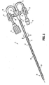
- FIG. 1 illustrates in perspective view, the hemodialysis catheter 10 in accordance with the principles of the present disclosure.
- Catheter 10 includes several components assembled together, namely, catheter hub or housing 12, elongated catheter member 14 extending distally from the catheter hub 12 and first and second extension tubes 16, 18 extending proximally from the catheter hub 12.
- Catheter system 10 further includes a pair of clamps 20 which are attached about each of extension tubes 16, 18.
- catheter hub 12 is advantageously dimensioned for engagement by the clinician.
- Catheter hub 12 includes proximal or trailing housing section 22 adjacent extension tubes 16, 18 and distal or leading housing section 24 adjacent catheter member 14.
- Proximal housing section 22 is adapted to receive respective first and second extension tubes 16, 18 in secured relation therewith.
- extension tubes 16, 18 are secured within respective extension conduits (not shown) of catheter hub 12 via an interference or frictional fit, cements or adhesives.
- Distal or leading housing section 24 of catheter hub 12 defines central opening (not shown) which receives catheter member 14.
- Catheter member 14 may be secured within central opening of distal housing section 24 via an interference or frictional fit, and, possibly supplemented with cements or adhesives.
- Catheter hub 12 may further include a pair of opposed wings 26 depending outwardly from the catheter hub 12. Wings 26 may serve as support elements to support first and second extension tubes 16, 18. In addition, it is contemplated that sutures may be wrapped about wings 26 to secure catheter hub 12 relative to the subject. In the alternative, wings 26 or catheter hub 12 may have an annular groove in its outer wall to receive the sutures. A suture may be wrapped within annular groove and subsequently secured relative to the subject.
- Catheter member 14 defines longitudinal axis " k “ and transverse axis " b “ in transverse relation to the longitudinal axis " k “.
- Catheter member 14 is preferably a dual lumen catheter having outer wall 28 and first and second longitudinal lumens 30, 32 separated by a septum wall 34 which may or may not extend the length the catheter member 14.
- Each of the first and second longitudinal lumens 30, 32 may define an oblong, kidney-shaped, or D-shaped opening in cross-section. Other lumen arrangements are also envisioned including circular, pie shaped etc. Coaxial lumens are also envisioned. As depicted in FIG.
- catheter member 14 may also include guidewire lumen 36 for reception and passage of a guidewire utilized to facilitate entry of the catheter member 14 within the vascular organ.
- first and second longitudinal lumens 30, 32 also may serve as the guidewire lumen in addition to its functioning to withdraw or deliver fluids.
- hemodialysis catheter 10 is represented as a dual lumen catheter, single or triple lumen catheters are also envisioned.
- FIG. 2B illustrates a triple lumen catheter with longitudinal lumens 30, 32a, 32b.
- Leading or distal end 38 of catheter member 14 will be discussed.
- Leading end 38 of catheter member 14 has catheter tip member 40 mounted thereto.
- Catheter tip member 40 will be discussed in greater detail hereinbelow.
- Leading or distal end 38 of catheter member 14 includes a pair of opposed openings 42, 44 arranged in its outer wall in diametrical relation and in fluid communication with respective first and second longitudinal lumens 30, 32.
- Each opening 42, 44 is spaced from catheter tip member 40.
- Each opening 42, 44 is characterized by having an arcuate recessed wall surface to define a partial generally arcuate opening as shown.
- Openings 42, 44 are symmetrically arranged about the longitudinal bisecting plane " m " of catheter member 14 (FIG. 4). Transverse axis " b “ of catheter member 14 is coincident with bisecting plane " m ". Openings 42, 44 permit passage of fluids during the procedure.
- openings 42, 44 include proximal or trailing opening segments 42a, 44a and distal or leading opening segments 42b, 44b. Trailing opening segments 42a, 44a each define an internal transverse dimension relative to transverse axis "b" which increases from proximal to distal end to define an enlarged tear-drop shaped configuration as shown.
- the wall portions defining opening segments 42a, 44a include first and second side surfaces 46, 48 which extend distally from a proximal locale or point of intersection 50 .
- first side surface 46 is in general parallel relation with the longitudinal axis "k".
- Second side surface 48 has an arcuate character and diverges outwardly from the longitudinal axis " k " and relative to first surface 46.
- First and second side surfaces 46,48 of trailing opening segments 42a, 44a may be linear or arcuate to provide a smooth inlet or outlet for the blood without substantially interrupting the flow of blood.
- Distal or leading opening segments 42b, 44b are in communication with trailing opening segments 42a, 44a.
- first side surface 46 extends continuously to end surface 52 which traverses longitudinal axis "k", e.g., is perpendicular to the longitudinal axis "k".
- Second side surface 48 may extend contiguously to an intermediate end surface 54 which traverses the longitudinal axis " k ", preferably, in parallel relation with end surface 52 .
- This configuration in effect, may define a leading opening segment 42b, 44b having a polygonal or rectangular profile and extending in transverse direction to longitudinal axis " k " of catheter member 14 .
- Leading segment 42b, 44b may accommodate greater fluid flow in the event a greater flow capacity is needed and may be incorporated into either or both openings 42, 44.
- Catheter tip member 40 includes proximal or trailing mounting member 56 and distal tapered portion 58 as best depicted in FIG. 9.
- Mounting member 56 cooperates with leading end 38 of catheter member to secure catheter tip member 40 to catheter member 14.
- proximal mounting member 56 includes first and second extensions 60, 62 which are positionable within respective longitudinal lumens 30, 32 of catheter member 14, and are adapted to establish an interference relationship with the inner walls defining the first and second longitudinal lumens 30, 32.
- Adhesives may be utilized to further secure catheter tip member 40 to catheter member 14.
- Second extension 62 further defines guidewire lumen 64 which serves as an extension of longitudinal lumen 32 for passage of the guidewire as best shown in FIG. 10.
- guidewire lumen 64 defines an inner diameter which substantially approximates the diameter of the guidewire intended for use with catheter 10 and less than an internal dimension of longitudinal lumen 32 to substantially minimize passage of fluid through the guidewire lumen 64.
- First extension 60 is devoid of a lumen.
- proximal surfaces 66,68 of respective first and second extensions 60,62 are contoured and angulated with respect to longitudinal axis " k " to assist in directing flow of fluid to and from catheter member 14.
- Distal tapered portion 58 of catheter tip member 40 is preferably tapered along its length to define a narrow profile for initial insertion within the body tissue.
- Tapered portion 58 defines guidewire lumen 70 in communication with guidewire lumen 64 of second extension 62.
- guidewire lumens 64,70 are a single lumen extending through catheter tip member 40 as shown.
- catheter tip member 40 defines a linear taper throughout its length to define a right conical configuration as depicted in FIG.11.
- distal tapered portion 58 of catheter tip member 40 defines an oblique conical configuration.
- guide wire lumens 64, 70 may be in general longitudinal alignment with second longitudinal lumen 32 of catheter member 14. This facilitates passage of catheter member 14 along a guidewire.
- Catheter tip member 40 may be fabricated from an elastomeric material or the like which presents an atraumatic surface to tissue. Any suitable biocompatible elastomer may be incorporated within catheter tip member 40. In an alternative embodiment, catheter tip member 40 is integrally or monolithically formed with leading end 38 of catheter member 14.
- Catheter member 14 is preferably flexible and may be formed by conventional injection molding or extrusion means. Outer wall 28 of catheter member 14 may include reinforcing material if desired. Catheter member 14 may have a pre-curved configuration in its normal state, i.e., having a preformed bend which it normally assumes in the absence of an external stressor, to conform to a body cavity or vessel in which the catheter member is to be positioned. Alternatively, catheter member 14 may be devoid of any normally curved orientation.
- catheter member 14 may further include at least one cuff 72 on its outer surface.
- Cuff 72 may include a fabric material and functions to be a site for tissue ingrowth for long term securing of catheter 10 in an indwelling position.
- cuff 72 may reside in the tunnel formed during the tunneling procedure. More than one cuff 72 may also be provided.
- Catheter member 14 may also include radiopaque markings or strips to facilitate the location of catheter within the body with a fluoroscope.
- First and second extension tubes 16, 18 may be any suitable tubing adapted to supply or withdrawal fluid to or from a body vessel.
- First and second extension tubes 16,18 preferably include a compressible material whereby the tubes 16, 18 may be selectively compressed via clamps 20 to substantially close the opening within the tubes 16, 18.
- the free or trailing ends of extension tubes 16, 18 remote from catheter hub 12 have adapters 74 mounted thereto.
- Adapters 74 may be any conventional luer connector or adapter utilized in an environment for administrating fluids.
- One suitable connection is a luer connector which may incorporate an external thread or cam for securing to a fluid source.
- Adapters 74 may be secured to extension tubes 16, 18 by any of the aforementioned means including friction or tolerance fit, adhesives, cements, etc.
- Clamps 20 are mounted about first and second extension tubes 16, 18. Each clamp 20 is adapted to move from a first open position in non compressive engagement with the respective extension tube 16, 18 to a second substantially closed position to compress the respective extension tube and close the lumen within the tube thereby preventing fluid flow in either direction.
- catheter 10 are fabricated from materials suitable for medical applications, such as, for example, polymerics or metals, such as titanium and stainless steel, depending on the particular catheter application and/or preference of a practitioner.
- Semi-rigid and rigid polymerics are contemplated for fabrication, as well as resilient materials, such as molded medical grade polyurethane, silicone, etc.
- Any sealing components of catheter 10 may be fabricated from low friction property materials such as polytetrafluoroethylene (PTFE) coated, PTFE impregnated, internally lubricated elastomers, etc.
- PTFE polytetrafluoroethylene
- one adapter 74 may be connected to the hemodialysis machine to withdraw blood through, e.g., longitudinal lumen 30 and extension tube 16. The remaining adapter 74 is intended to return the blood through extension tube 18 and longitudinal lumen 32 for delivery to the patient. Clamps 20 may be manipulated between their respective first open and second closed positions as desired.
- either longitudinal lumen 30, 32 may serve as the intake lumen or the return lumen.
- the blood being received within opening 42 would tend to flow under suction supplied by the hemodialysis machine toward or within the narrower proximal segment 42a of the opening 42.
- the arcuate configuration of the opening 42 adequately accommodates this flow requirement.
- the blood being returned from the hemodialysis machine via return lumen 32 would flow under pressure through opening 44 adjacent the enlarged distal area or segment 44b of the opening 42.
- the enlarged distal area or segment 44b is dimensioned to permit sufficient blood flow without degrading flow performance.
- recirculation of "cleaned" blood is substantially minimized.
- longitudinal lumen 30 serves as the return lumen where blood is returned to the patient from the hemodialysis machine and longitudinal lumen 32 serves as the intake lumen. It is noted that symmetrical characteristics of openings 42, 44 enables either longitudinal lumen 30, 32 to function in the intake or return capacity.
- FIG. 12 illustrates an alternate embodiment of the present disclosure.
- catheter member 14 includes first and second openings 80, 82 in communication with respective longitudinal lumens 30, 32 of catheter member 14. Opening 82 is shown in phantom.
- First and second openings 80, 82 are preferably symmetrically arranged about a median plane " m " bisecting the catheter member 14 and coincident with longitudinal axis "k" in a similar manner to the embodiment of FIG. 1.
- Openings 80, 82 each define first and second side wall surfaces 84, 86 which commence at proximal location 88 and extend along the longitudinal axis " k ".
- Side wall surface 84 may be parallel to longitudinal axis " k " and side wall surface 86 diverges outwardly from the longitudinal axis " k “ in the distal direction. Both side wall surfaces 84, 86 extend to end surface 90 which traverses longitudinal axis " k “ of catheter member 14, i.e., and may generally extend along the transverse axis " b “ in transverse relation to the longitudinal axis " k ". Side and end wall surfaces 84, 86, 90 may have an arcuate contour to provide a smooth inlet or outlet for the blood without substantially interrupting the flow of blood through the openings.
- the catheter of the embodiment of FIG. 12 may be used in a similar manner to the embodiment of FIG. 1 and in a reverse flow capacity as discussed hereinabove.
- openings 80, 82 define a distal opening segment which is greater than the proximal opening segment whereby blood may be withdrawn through the proximal segment of a first opening, e.g. opening 80, through longitudinal lumen 30 of catheter member 14 and returned via longitudinal lumen 32 and through the enlarged distal segment of opening 82.
Landscapes
- Health & Medical Sciences (AREA)
- Life Sciences & Earth Sciences (AREA)
- Heart & Thoracic Surgery (AREA)
- Hematology (AREA)
- Public Health (AREA)
- Anesthesiology (AREA)
- Biomedical Technology (AREA)
- Engineering & Computer Science (AREA)
- Veterinary Medicine (AREA)
- Animal Behavior & Ethology (AREA)
- General Health & Medical Sciences (AREA)
- Pulmonology (AREA)
- Biophysics (AREA)
- Vascular Medicine (AREA)
- Urology & Nephrology (AREA)
- Cardiology (AREA)
- External Artificial Organs (AREA)
- Media Introduction/Drainage Providing Device (AREA)
Abstract
Description
- The present disclosure relates to a catheter assembly, and, in particular, relates to a hemodialysis catheter adapted to facilitate bidirectional fluid flow.
- Catheters are flexible medical instruments intended for the withdrawal and introduction of fluids relative to body cavities, ducts and vessels. Catheters have particular application in hemodialysis procedures where blood is withdrawn from a blood vessel for treatment and subsequently returned to the blood vessel for circulation. Known hemodialysis catheters include multiple lumens, such as dual lumen or triple lumen catheters, permitting bi-directional fluid flow within the catheter whereby one lumen is dedicated for withdrawal of blood and the other lumen is dedicated for returning the treated blood to the vessel. During an exemplary hemodialysis procedure, a multiple lumen catheter is inserted into a body and blood is withdrawn through an arterial lumen of the catheter. The removed blood is directed to a hemodialysis unit which dialyzes, or purifies, the blood to remove waste and toxins. The dialyzed blood is returned to the patient through a venous lumen of the catheter.
- Conventional hemodialysis catheters incorporate various catheter tip designs, such as a staggered arterial (inlet) and venous (outlet) design, to ensure blood returning to the patient will be expelled downstream from the arterial inlet which is located upstream to draw the blood from the subject. Unfortunately, poor flow performance is a common problem with hemodialysis catheters, typically, due to occlusion resulting from fibrin sheath formation, thrombus formation and positional occlusion. Flow occlusion is primarily caused by blockage of the arterial lumen. Resolving poor flow is required to deliver the dialysis treatment to the patient. Current measures taken to resolve flow occlusion include repositioning the patient, flushing the lumens and reversing the blood lines of the catheter to the hemodialysis unit. This, however, creates a situation where cleaned blood is expelled upstream relative to the catheter inlet, which undesirably increases the potential for clean blood to be drawn back into the catheter resulting in "recirculation" of the blood. "Recirculation" creates inefficient dialysis by increasing treatment time to reach prescribed blood cleanliness levels.
- Accordingly, the present disclosure is directed to further improvements in hemodialysis catheters and systems used therewith. A medical catheter includes an elongate catheter member defining a longitudinal axis and a transverse axis, and having a proximal end and a distal end. The elongate catheter member includes an outer member and at least one longitudinal lumen within the outer member for passage of fluids. The outer member has an elongate opening therethrough in communication with the at least one longitudinal lumen and being spaced from the distal end and bound by wall portions of the outer member. The elongate opening permits fluids to pass between the at least one longitudinal lumen and locations external to the elongate catheter member, and defines a transverse dimension increasing from proximal to distal.
- The wall portions of the outer member may include first and second sides extending at least along the longitudinal axis. At least one of the first and second sides is arranged to diverge outwardly with relation to the longitudinal axis from proximal to distal to thereby increase the transverse dimension of the elongate opening. The first and second sides may be arranged to generally intersect at a proximal location and extend along the longitudinal axis. The wall portions of the outer member further may include an end wall extending at least along the transverse axis. The transverse dimension of the elongate opening may be greatest adjacent the end wall.
- In another alternative, the wall portions include an intermediate wall coterminous with the first side and extending outwardly therefrom. The intermediate wall is arranged in general parallel relation with the end wall. The intermediate wall and the end wall generally may extend along the transverse axis in general transverse relation to the longitudinal axis.
- The elongate catheter may include first and second longitudinal lumens and corresponding first and second elongate openings within the outer member in communication with the first and second longitudinal lumens and being bound by respective wall portions of the outer member. The first and second elongate openings are arranged in symmetrical relation with respect to a median plane bisecting the elongate catheter member.
- In another embodiment, a medical catheter includes an elongate catheter member defining a longitudinal axis, and having a proximal end and a distal end. The elongate catheter member includes an outer member and at least one longitudinal lumen within the outer member. The outer member has an elongate opening therethrough in fluid communication with the at least one longitudinal lumen and being at least bound by inner opening surfaces of the outer member. The elongate opening defines an effective area along the longitudinal axis which increases from proximal to distal, whereby when in a first mode of operation of the elongated catheter member, fluids are substantially withdrawn through a proximal segment of the elongate opening and into the at least one longitudinal lumen, and when in a second mode of operation of the elongated catheter member fluids are delivered from the at least one longitudinal lumen and substantially through a distal segment of the elongate opening. The inner opening surfaces of the outer member include first and second side opening surfaces which generally converge at a proximal location. The elongate opening may define a general tear drop shaped portion. Preferably, the proximal segment of the elongate opening includes the tear drop shaped portion and the distal segment of the elongate opening includes a general polygonal-shaped portion.
- The elongate catheter may include first and second longitudinal lumens and corresponding first and second elongate openings within the outer member in communication with the first and second longitudinal lumens. The first and second elongate openings are arranged in symmetrical relation with respect to a median plane bisecting the elongate catheter member. As a further alternative, the elongate catheter includes first, second and third longitudinal lumens and corresponding first, second and third elongate openings within the outer member in communication with the first, second and third longitudinal lumens.
- In another embodiment, a dialysis catheter includes an elongate catheter member having an outer member defining proximal and distal ends and a longitudinal axis, and having first and second longitudinal lumens arranged in side by side relation. The outer member includes first and second openings defined within wall surfaces of the outer member and arranged in symmetrical relation with respect to a longitudinal bisecting plane bisecting the elongate catheter member. The first and second openings are in respective fluid communication with the first and second longitudinal lumens and each defines an area within the wall surfaces greater at a distal location of the elongate opening relative to a proximal location of the elongate opening. The first and second longitudinal lumens are each selectively adapted for removal or delivery of fluids where the fluids may be substantially withdrawn through the area adjacent the proximal location of the opening and where the fluids may be delivered through the area adjacent the distal location of the elongate opening.
- A catheter tip member may be mounted to the catheter member. The catheter tip member may define a tapered configuration. The catheter tip member further may include a guide wire lumen therethrough. In one embodiment, the catheter tip member includes first and second mounting extensions which are receivable within the respective first and second longitudinal lumens of the catheter member to connect the catheter tip member to the catheter member. The mounting extensions may include internal contoured wall surfaces which cooperate to direct and receive fluids through the respective first and second openings of the catheter member.
- Preferred embodiments of the present disclosure will be better understood with reference to the accompanying drawings wherein:
- FIG. 1 is a perspective view of the acute hemodialysis catheter in accordance with the principles of the present disclosure;
- FIG. 2 is a cross-sectional view taken along the lines 2-2 of FIG. 1 illustrating a dual lumen catheter;
- FIG. 2A is a view similar to the view of FIG. 2 illustrating an alternate embodiment incorporating a dual lumen catheter with a guide wire lumen;
- FIG. 2B is a view similar to the view of FIG. 2 illustrating an alternate embodiment incorporating a triple lumen catheter;
- FIGS. 3-4 are perspective views of the leading end of the hemodialysis catheter;
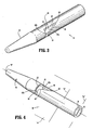
- FIGS. 5-6 are side plan views of the leading end of the hemodialysis catheter;
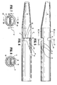
- FIG. 7 is a cross-sectional view taken along the lines 8-8 of FIG. 5;
- FIG. 8 is a cross-sectional view taken along the lines 9-9 of FIG. 5;
- FIG. 9 is a perspective view with parts separated of the leading end of the hemodialysis catheter;
- FIG. 10 is a side cross-sectional view taken along the lines 10-10 of FIG. 8;
- FIG. 11 is a side cross-sectional view taken along the lines 11-11 of FIG. 8; and
- FIG. 12 is a side plan view of an alternate embodiment of the leading end of the hemodialysis catheter.
- The exemplary embodiments of the catheter and methods of use disclosed are discussed in terms of medical catheters for the administration of fluids relative to the body of a subject and, more particularly, in terms of an acute hemodialysis catheter. However, it is envisioned that the present disclosure may be employed with a range of catheter applications including surgical, diagnostic and related treatments of diseases, body ailments, of a subject. It is further envisioned that the principles relating to the catheter disclosed include employment with various catheter related procedures, such as, for example, hemodialysis, cardiac, abdominal, urinary, intestinal, in chronic and/or acute applications. Moreover, the catheter can be used for administration or withdrawal of fluids such as, for example, medication, saline, bodily fluids, blood and urine.
- In the discussion that follows, the term "proximal" or "trailing" will refer to the portion of a structure that is closer to a clinician, while the term "distal" or "leading" will refer to the portion that is further from the clinician. As used herein, the term "subject" refers to a human patient or other animal. The term "clinician" refers to a doctor, nurse or other care provider and may include support personnel.
- Referring now to the drawings wherein like components are designated by like reference numerals throughout the several views, FIG. 1 illustrates in perspective view, the
hemodialysis catheter 10 in accordance with the principles of the present disclosure.Catheter 10 includes several components assembled together, namely, catheter hub orhousing 12,elongated catheter member 14 extending distally from thecatheter hub 12 and first andsecond extension tubes catheter hub 12.Catheter system 10 further includes a pair ofclamps 20 which are attached about each ofextension tubes - With continued reference to FIG. 1,
catheter hub 12 is advantageously dimensioned for engagement by the clinician.Catheter hub 12 includes proximal or trailinghousing section 22adjacent extension tubes housing section 24adjacent catheter member 14.Proximal housing section 22 is adapted to receive respective first andsecond extension tubes extension tubes catheter hub 12 via an interference or frictional fit, cements or adhesives. Distal or leadinghousing section 24 ofcatheter hub 12 defines central opening (not shown) which receivescatheter member 14.Catheter member 14 may be secured within central opening ofdistal housing section 24 via an interference or frictional fit, and, possibly supplemented with cements or adhesives. -
Catheter hub 12 may further include a pair ofopposed wings 26 depending outwardly from thecatheter hub 12.Wings 26 may serve as support elements to support first andsecond extension tubes wings 26 to securecatheter hub 12 relative to the subject. In the alternative,wings 26 orcatheter hub 12 may have an annular groove in its outer wall to receive the sutures. A suture may be wrapped within annular groove and subsequently secured relative to the subject. - Referring now to FIG. 2, in conjunction with FIG. 1,
elongated catheter member 14 will be discussed.Catheter member 14 defines longitudinal axis "k" and transverse axis "b" in transverse relation to the longitudinal axis "k".Catheter member 14 is preferably a dual lumen catheter havingouter wall 28 and first and secondlongitudinal lumens septum wall 34 which may or may not extend the length thecatheter member 14. Each of the first and secondlongitudinal lumens catheter member 14 may also includeguidewire lumen 36 for reception and passage of a guidewire utilized to facilitate entry of thecatheter member 14 within the vascular organ. Alternatively, one of first and secondlongitudinal lumens hemodialysis catheter 10 is represented as a dual lumen catheter, single or triple lumen catheters are also envisioned. FIG. 2B illustrates a triple lumen catheter withlongitudinal lumens - With particular reference to FIGS. 3-4, leading or
distal end 38 ofcatheter member 14 will be discussed. Leadingend 38 ofcatheter member 14 hascatheter tip member 40 mounted thereto.Catheter tip member 40 will be discussed in greater detail hereinbelow. Leading ordistal end 38 ofcatheter member 14 includes a pair ofopposed openings longitudinal lumens opening catheter tip member 40. Eachopening Openings catheter member 14 is coincident with bisecting plane "m".Openings - As best depicted in FIGS. 3 -7,
openings opening segments segments segments opening segments intersection 50. In one embodiment,first side surface 46 is in general parallel relation with the longitudinal axis "k".Second side surface 48 has an arcuate character and diverges outwardly from the longitudinal axis "k" and relative tofirst surface 46. First and second side surfaces 46,48 of trailingopening segments - Distal or leading opening
segments opening segments first side surface 46 extends continuously to endsurface 52 which traverses longitudinal axis "k", e.g., is perpendicular to the longitudinal axis "k".Second side surface 48 may extend contiguously to anintermediate end surface 54 which traverses the longitudinal axis "k", preferably, in parallel relation withend surface 52. This configuration, in effect, may define aleading opening segment catheter member 14. Leadingsegment openings - Referring now to FIGS. 6-11,
catheter tip member 40 will be discussed.Catheter tip member 40 includes proximal or trailing mountingmember 56 and distal taperedportion 58 as best depicted in FIG. 9. Mountingmember 56 cooperates with leadingend 38 of catheter member to securecatheter tip member 40 tocatheter member 14. In one embodiment, proximal mountingmember 56 includes first andsecond extensions longitudinal lumens catheter member 14, and are adapted to establish an interference relationship with the inner walls defining the first and secondlongitudinal lumens catheter tip member 40 tocatheter member 14.Second extension 62 further definesguidewire lumen 64 which serves as an extension oflongitudinal lumen 32 for passage of the guidewire as best shown in FIG. 10. Preferably,guidewire lumen 64 defines an inner diameter which substantially approximates the diameter of the guidewire intended for use withcatheter 10 and less than an internal dimension oflongitudinal lumen 32 to substantially minimize passage of fluid through theguidewire lumen 64.First extension 60 is devoid of a lumen. As best depicted in FIG. 10,proximal surfaces second extensions catheter member 14. - Distal tapered
portion 58 ofcatheter tip member 40 is preferably tapered along its length to define a narrow profile for initial insertion within the body tissue.Tapered portion 58 definesguidewire lumen 70 in communication withguidewire lumen 64 ofsecond extension 62. Preferably, guidewirelumens catheter tip member 40 as shown. When viewed along one profile,catheter tip member 40 defines a linear taper throughout its length to define a right conical configuration as depicted in FIG.11. However, when viewed along a second profile rotated 90 degrees as depicted in FIG. 10, distal taperedportion 58 ofcatheter tip member 40 defines an oblique conical configuration. With this arrangement,guide wire lumens longitudinal lumen 32 ofcatheter member 14. This facilitates passage ofcatheter member 14 along a guidewire. -
Catheter tip member 40 may be fabricated from an elastomeric material or the like which presents an atraumatic surface to tissue. Any suitable biocompatible elastomer may be incorporated withincatheter tip member 40. In an alternative embodiment,catheter tip member 40 is integrally or monolithically formed with leadingend 38 ofcatheter member 14. -
Catheter member 14 is preferably flexible and may be formed by conventional injection molding or extrusion means.Outer wall 28 ofcatheter member 14 may include reinforcing material if desired.Catheter member 14 may have a pre-curved configuration in its normal state, i.e., having a preformed bend which it normally assumes in the absence of an external stressor, to conform to a body cavity or vessel in which the catheter member is to be positioned. Alternatively,catheter member 14 may be devoid of any normally curved orientation. - Referring again to FIG. 1,
catheter member 14 may further include at least onecuff 72 on its outer surface.Cuff 72 may include a fabric material and functions to be a site for tissue ingrowth for long term securing ofcatheter 10 in an indwelling position. For example,cuff 72 may reside in the tunnel formed during the tunneling procedure. More than onecuff 72 may also be provided.Catheter member 14 may also include radiopaque markings or strips to facilitate the location of catheter within the body with a fluoroscope. - First and
second extension tubes second extension tubes tubes clamps 20 to substantially close the opening within thetubes extension tubes catheter hub 12 haveadapters 74 mounted thereto.Adapters 74 may be any conventional luer connector or adapter utilized in an environment for administrating fluids. One suitable connection is a luer connector which may incorporate an external thread or cam for securing to a fluid source.Adapters 74 may be secured toextension tubes -
Clamps 20 are mounted about first andsecond extension tubes clamp 20 is adapted to move from a first open position in non compressive engagement with therespective extension tube - The components of
catheter 10 are fabricated from materials suitable for medical applications, such as, for example, polymerics or metals, such as titanium and stainless steel, depending on the particular catheter application and/or preference of a practitioner. Semi-rigid and rigid polymerics are contemplated for fabrication, as well as resilient materials, such as molded medical grade polyurethane, silicone, etc. Any sealing components ofcatheter 10 may be fabricated from low friction property materials such as polytetrafluoroethylene (PTFE) coated, PTFE impregnated, internally lubricated elastomers, etc. One skilled in the art, however, will realize that other materials and fabrication methods suitable for assembly and manufacture, in accordance with the present disclosure, also would be appropriate. - In a hemodialysis application, one
adapter 74 may be connected to the hemodialysis machine to withdraw blood through, e.g.,longitudinal lumen 30 andextension tube 16. The remainingadapter 74 is intended to return the blood throughextension tube 18 andlongitudinal lumen 32 for delivery to the patient.Clamps 20 may be manipulated between their respective first open and second closed positions as desired. - In use, either
longitudinal lumen lumen 30 is to serve as the intake lumen, the blood being received within opening 42 would tend to flow under suction supplied by the hemodialysis machine toward or within the narrowerproximal segment 42a of theopening 42. However, the arcuate configuration of theopening 42 adequately accommodates this flow requirement. The blood being returned from the hemodialysis machine viareturn lumen 32 would flow under pressure through opening 44 adjacent the enlarged distal area orsegment 44b of theopening 42. The enlarged distal area orsegment 44b is dimensioned to permit sufficient blood flow without degrading flow performance. In addition, in that the blood is primarily being returned within the distal area orsegment 44b of opening 44 downstream of theproximal segment 42a of correspondingopening 42, recirculation of "cleaned" blood is substantially minimized. - If catheter occlusion or thrombus formation is suspected, the clinician may reverse the flow of fluids through the line whereby
longitudinal lumen 30 serves as the return lumen where blood is returned to the patient from the hemodialysis machine andlongitudinal lumen 32 serves as the intake lumen. It is noted that symmetrical characteristics ofopenings longitudinal lumen - FIG. 12 illustrates an alternate embodiment of the present disclosure. In accordance with this embodiment,
catheter member 14 includes first andsecond openings longitudinal lumens catheter member 14.Opening 82 is shown in phantom. First andsecond openings catheter member 14 and coincident with longitudinal axis "k" in a similar manner to the embodiment of FIG. 1.Openings proximal location 88 and extend along the longitudinal axis "k".Side wall surface 84 may be parallel to longitudinal axis "k" andside wall surface 86 diverges outwardly from the longitudinal axis "k" in the distal direction. Both side wall surfaces 84, 86 extend to endsurface 90 which traverses longitudinal axis "k" ofcatheter member 14, i.e., and may generally extend along the transverse axis "b" in transverse relation to the longitudinal axis "k". Side and end wall surfaces 84, 86, 90 may have an arcuate contour to provide a smooth inlet or outlet for the blood without substantially interrupting the flow of blood through the openings. The catheter of the embodiment of FIG. 12 may be used in a similar manner to the embodiment of FIG. 1 and in a reverse flow capacity as discussed hereinabove. Specifically, the arrangement ofopenings opening 80, throughlongitudinal lumen 30 ofcatheter member 14 and returned vialongitudinal lumen 32 and through the enlarged distal segment ofopening 82. - Although the illustrative embodiments of the present disclosure have been described herein with reference to the accompanying drawings, it is to be understood that the disclosure is not limited to those precise embodiments, and that various other changes and modifications may be effected therein by one skilled in the art without departing from the scope or spirit of the disclosure.
Claims (20)
- A medical catheter, which comprises:an elongate catheter member defining a longitudinal axis and a transverse axis transverse to the longitudinal axis, and having a proximal end and a distal end, the elongate catheter member including an outer member and at least one longitudinal lumen within the outer member for passage of fluids, the outer member having an elongate opening therethrough in communication with the at least one longitudinal lumen and being spaced from the distal end and bound by wall portions of the outer member, the elongate opening permitting fluids to pass between the at least one longitudinal lumen and locations external to the elongate catheter member, and defining a transverse dimension increasing from proximal to distal.
- The medical catheter according to claim 1 wherein the wall portions of the outer member include first and second sides extending at least along the longitudinal axis, at least one of the first and second sides arranged to diverge outwardly with relation to the longitudinal axis from proximal to distal to thereby increase the transverse dimension of the elongate opening.
- The medical catheter according to claim 2 wherein the first and second sides are arranged to generally intersect at a proximal location and extend along the longitudinal axis.
- The medical catheter according to claim 3 wherein the wall portions of the outer member include an end wall extending at least along the transverse axis.
- The medical catheter according to claim 4 wherein the transverse dimension of the elongate opening is greatest adjacent the end wall.
- The medical catheter according to claim 5 wherein the wall portions include an intermediate wall coterminous with the first side and extending outwardly therefrom.
- The medical catheter according to claim 6 wherein the intermediate wall is arranged in general parallel relation with the end wall.
- The medical catheter according to claim 7 wherein the intermediate wall and the end wall generally extend along the transverse axis in general transverse relation with the longitudinal axis.
- The medical catheter according to claim 1 wherein the elongate catheter includes first and second longitudinal lumens and corresponding first and second elongate openings within the outer member in communication with the first and second longitudinal lumens and being bound by respective wall portions of the outer member.
- The medical catheter according to claim 9 wherein the first and second elongate openings are arranged in symmetrical relation with respect to a median plane bisecting the elongate catheter member.
- A medical catheter, which comprises:an elongate catheter member defining a longitudinal axis, and having a proximal end and a distal end, the elongate catheter member including an outer member and at least one longitudinal lumen within the outer member, the outer member having an elongate opening therethrough in fluid communication with the at least one longitudinal lumen and being at least bound by inner wall surfaces of the outer member, the elongate opening defining an effective area along the longitudinal axis which increases from proximal to distal, whereby when in a first mode of operation of the elongated catheter member fluids are substantially withdrawn through a proximal area of the elongate opening and into the at least one longitudinal lumen, and when in a second mode of operation of the elongated catheter member fluids are delivered from the at least one longitudinal lumen and substantially through a distal area of the elongate opening.
- The medical catheter according to claim 11 wherein the inner wall surfaces of the outer member include first and second side surfaces which generally converge at a proximal location.
- The medical catheter according to claim 12 wherein the elongate opening defines a general tear drop shaped portion.
- The medical catheter according to claim 12 wherein the elongate catheter includes first and second longitudinal lumens and corresponding first and second elongate openings within the outer member in communication with the first and second longitudinal lumens.
- The medical catheter according to claim 14 wherein the first and second elongate openings are arranged in symmetrical relation with respect to a median plane bisecting the elongate catheter member.
- The medical catheter according to claim 12 wherein the elongate catheter includes first, second and third longitudinal lumens and corresponding first, second and third elongate openings within the outer member in communication with the first, second and third longitudinal lumens.
- A dialysis catheter, which comprises:an elongate catheter member including an outer member defining proximal and distal ends and a longitudinal axis, and having first and second longitudinal lumens arranged in side by side relation, the outer member including first and second openings defined within wall surfaces of the outer member and arranged in symmetrical relation with respect to a longitudinal bisecting plane bisecting the elongate catheter member, the first and second openings in respective fluid communication with the first and second longitudinal lumens and each defining an area within the wall surfaces greater at a distal location of the elongate opening relative to a proximal location of the elongate opening, the first and second longitudinal lumens each being selectively adapted for removal of fluids where the fluids are substantially withdrawn through the area adjacent the proximal location of the opening and for delivery of fluids where the fluids are delivered through the area adjacent the distal location of the elongate opening.
- The dialysis catheter according to claim 17 including a catheter tip member mounted to the catheter member, the catheter tip member defining a tapered configuration.
- The dialysis catheter according to claim 18 wherein the catheter tip member includes a guide wire lumen therethrough.
- The dialysis catheter according to claim 19 wherein the catheter tip member includes first and second mounting extensions receivable within the respective first and second longitudinal lumens of the catheter member to connect the catheter tip member to the catheter member, the mounting extensions including internal contoured wall surfaces which cooperate to direct and receive fluids through the respective first and second openings of the catheter member.
Applications Claiming Priority (1)
| Application Number | Priority Date | Filing Date | Title |
|---|---|---|---|
| US11/541,043 US9168355B2 (en) | 2006-09-29 | 2006-09-29 | Acute hemodialysis catheter assembly |
Publications (3)
| Publication Number | Publication Date |
|---|---|
| EP1905476A2 true EP1905476A2 (en) | 2008-04-02 |
| EP1905476A3 EP1905476A3 (en) | 2008-05-28 |
| EP1905476B1 EP1905476B1 (en) | 2017-11-01 |
Family
ID=38820000
Family Applications (1)
| Application Number | Title | Priority Date | Filing Date |
|---|---|---|---|
| EP07253689.9A Active EP1905476B1 (en) | 2006-09-29 | 2007-09-18 | Acute hemodialysis catheter assembly |
Country Status (4)
| Country | Link |
|---|---|
| US (1) | US9168355B2 (en) |
| EP (1) | EP1905476B1 (en) |
| CA (1) | CA2602331A1 (en) |
| ES (1) | ES2658103T3 (en) |
Cited By (13)
| Publication number | Priority date | Publication date | Assignee | Title |
|---|---|---|---|---|
| EP2305337A3 (en) * | 2009-09-30 | 2011-11-30 | Tyco Healthcare Group LP | Medical catheter having a design providing low recirculation and reversibility |
| EP2392370A3 (en) * | 2010-06-07 | 2013-01-23 | Rex Medical, L.P. | Dialysis catheter |
| US8500674B2 (en) | 2001-01-09 | 2013-08-06 | Rex Medical, L.P. | Dialysis catheter |
| EP2712647A1 (en) * | 2012-09-28 | 2014-04-02 | Covidien LP | Symmetrical tip acute catheter |
| US8747343B2 (en) | 2011-09-30 | 2014-06-10 | Covidien Lp | Hemodialysis catheter with improved side opening design |
| US8876752B2 (en) | 2010-09-24 | 2014-11-04 | Covidien Lp | Dialysis catheter |
| US9072867B2 (en) | 2011-09-30 | 2015-07-07 | Covidien Lp | Catheter with external flow channel |
| GB2552924A (en) * | 2016-05-13 | 2018-02-21 | Gbuk Ltd | Feeding tube |
| EP3388104A1 (en) * | 2017-04-11 | 2018-10-17 | B. Braun Melsungen AG | Flexible hose and method for its manufacture |
| EP3391927A3 (en) * | 2010-08-10 | 2019-02-27 | Becton, Dickinson and Company | A catheter hole having a flow breaking feature |
| CN109432518A (en) * | 2018-12-17 | 2019-03-08 | 郭克存 | A kind of Urology Surgery clinic urethral catheterization device |
| US10549068B2 (en) | 2008-04-22 | 2020-02-04 | Becton, Dickinson And Company | Catheter hole having an inclined trailing edge |
| US10610668B2 (en) | 2016-10-05 | 2020-04-07 | Becton, Dickinson And Company | Catheter with an asymmetric tip |
Families Citing this family (40)
| Publication number | Priority date | Publication date | Assignee | Title |
|---|---|---|---|---|
| US6758836B2 (en) | 2002-02-07 | 2004-07-06 | C. R. Bard, Inc. | Split tip dialysis catheter |
| US7393339B2 (en) | 2003-02-21 | 2008-07-01 | C. R. Bard, Inc. | Multi-lumen catheter with separate distal tips |
| US20040243095A1 (en) | 2003-05-27 | 2004-12-02 | Shekhar Nimkar | Methods and apparatus for inserting multi-lumen spit-tip catheters into a blood vessel |
| US8992454B2 (en) | 2004-06-09 | 2015-03-31 | Bard Access Systems, Inc. | Splitable tip catheter with bioresorbable adhesive |
| US9126011B2 (en) | 2006-03-24 | 2015-09-08 | Merit Medical Systems, Inc. | Anti-clotting indwelling catheter |
| US8029457B2 (en) | 2006-03-24 | 2011-10-04 | Aat Catheter Technologies, Llc | Indwelling catheter with anti-clotting features |
| WO2008109549A2 (en) * | 2007-03-02 | 2008-09-12 | Tyco Healthcare Group Lp | Catheter adapter apparatus |
| EP2214765A4 (en) | 2007-10-17 | 2011-08-10 | Bard Access Systems Inc | Manufacture of split tip catheters |
| US8292841B2 (en) * | 2007-10-26 | 2012-10-23 | C. R. Bard, Inc. | Solid-body catheter including lateral distal openings |
| US8066660B2 (en) | 2007-10-26 | 2011-11-29 | C. R. Bard, Inc. | Split-tip catheter including lateral distal openings |
| JP5452498B2 (en) * | 2007-11-01 | 2014-03-26 | シー・アール・バード・インコーポレーテッド | Catheter assembly including triple lumen end |
| US9579485B2 (en) | 2007-11-01 | 2017-02-28 | C. R. Bard, Inc. | Catheter assembly including a multi-lumen configuration |
| EP2244760B8 (en) * | 2008-01-28 | 2022-07-20 | Implantica Patent Ltd. | An implantable drainage device |
| US8523828B2 (en) | 2008-12-30 | 2013-09-03 | Covidien Lp | Clamping assembly for use with a catheter |
| US8419694B2 (en) | 2008-12-30 | 2013-04-16 | Covidien Lp | Extension tube clamps for use with a catheter |
| US8221388B2 (en) * | 2009-04-22 | 2012-07-17 | Tyco Healthcare Group Lp | Biased clamping assemblies |
| US20110106099A1 (en) * | 2009-10-29 | 2011-05-05 | Medtronic, Inc. | Lead extraction device |
| WO2012071413A2 (en) * | 2010-11-23 | 2012-05-31 | The Trustees Of Columbia University In The City Of New York | Assembly and method for coronary sinus cannulation |
| US8795253B2 (en) * | 2011-04-05 | 2014-08-05 | Sorin Group Italia S.R.L. | Bi-directional perfusion cannula |
| CA2843145A1 (en) * | 2011-07-25 | 2013-01-31 | Acclarent, Inc. | Devices and methods for transnasal dilation and irrigation of the sinuses |
| AU2012287264A1 (en) * | 2011-07-28 | 2014-02-13 | Acclarent, Inc. | Improved device and method for dilating an airway stenosis |
| EP3257545A1 (en) | 2011-08-11 | 2017-12-20 | Phase One Medical, LLC | Apparatus for the dialysis of blood |
| WO2013101912A1 (en) * | 2011-12-29 | 2013-07-04 | Cook Medical Technoloies Llc | Space-optimized visualization catheter with camera train holder |
| US9668643B2 (en) | 2011-12-29 | 2017-06-06 | Cook Medical Technologies Llc | Space-optimized visualization catheter with oblong shape |
| AU2015201947B2 (en) * | 2012-09-28 | 2016-08-25 | Covidien Lp | Symmetrical tip acute catheter |
| US10252023B2 (en) * | 2013-01-11 | 2019-04-09 | C. R. Bard, Inc. | Curved catheter and methods for making same |
| USD748252S1 (en) | 2013-02-08 | 2016-01-26 | C. R. Bard, Inc. | Multi-lumen catheter tip |
| EP3071284B1 (en) * | 2013-11-21 | 2019-08-14 | C.R. Bard, Inc. | Catheter assembly including a multi-lumen configuration |
| WO2016011091A1 (en) | 2014-07-14 | 2016-01-21 | C. R. Bard, Inc. | Apparatuses, systems, and methods for inserting split tip catheters having enhanced stiffening and guiding features |
| DE102014226628A1 (en) * | 2014-12-19 | 2016-06-23 | Raumedic Ag | Multi-lumen microcatheter tube and method of making a multi-lumen microcatheter tube |
| US10688296B2 (en) * | 2015-12-24 | 2020-06-23 | Heriot Eyecare Pty. Ltd. | Pressure management device |
| US9861734B2 (en) | 2016-03-21 | 2018-01-09 | King Saud University | Bifurcated peritoneal catheter |
| EP3524195A4 (en) * | 2016-10-06 | 2020-05-06 | Kitazato Corporation | TOOL FOR TRANSPLANTATION OF LIVING CELLS |
| WO2019066728A1 (en) * | 2017-09-30 | 2019-04-04 | Tay Hsien Tsung | Obturator, sheath and method for using same |
| USD905853S1 (en) | 2018-02-27 | 2020-12-22 | Medical Components, Inc. | Catheter tip |
| US20210330931A1 (en) * | 2018-09-05 | 2021-10-28 | Vanderbilt University | Pediatric catheter |
| US20230015088A1 (en) * | 2019-12-27 | 2023-01-19 | Bellco S.R.L. | Catheter with biconcave side opening |
| USD984880S1 (en) | 2020-11-06 | 2023-05-02 | Medical Components, Inc. | Clamp with indicator |
| CN112386757B (en) * | 2020-11-11 | 2021-09-21 | 广东百合医疗科技股份有限公司 | Hemodialysis catheter and production method thereof |
| DE102020214618A1 (en) | 2020-11-19 | 2022-05-19 | B. Braun Melsungen Aktiengesellschaft | Soft elastic catheter tip |
Citations (5)
| Publication number | Priority date | Publication date | Assignee | Title |
|---|---|---|---|---|
| EP0299622A2 (en) | 1987-07-17 | 1989-01-18 | Minnesota Mining And Manufacturing Company | Venous return catheter |
| US20020121282A1 (en) | 2001-01-09 | 2002-09-05 | Mcguckin James F. | Dialysis catheter and methods of insertion |
| US20030032918A1 (en) | 2000-08-30 | 2003-02-13 | Quinn David G. | Catheter |
| US20030191425A1 (en) | 2002-04-04 | 2003-10-09 | Melvin Rosenblatt | Blood treatment catheter and method |
| US20070100298A1 (en) | 2002-04-04 | 2007-05-03 | Angiodynamics, Inc. | Catheter fluid lock method and device |
Family Cites Families (142)
| Publication number | Priority date | Publication date | Assignee | Title |
|---|---|---|---|---|
| CA1092927A (en) | 1979-12-28 | 1981-01-06 | Allentyne Limited | Hemodialysis cannula for subclavian insertion |
| US4403983A (en) | 1981-11-06 | 1983-09-13 | Shiley Incorporated | Dual lumen subclavian cannula |
| US4626240A (en) | 1981-11-06 | 1986-12-02 | Shiley Incorporated | Dual lumen subclavian cannula |
| US4568329A (en) | 1982-03-08 | 1986-02-04 | Mahurkar Sakharam D | Double lumen catheter |
| US4692141A (en) | 1982-03-08 | 1987-09-08 | Mahurkar Sakharam D | Double lumen catheter |
| US4619643A (en) | 1983-07-25 | 1986-10-28 | Bai Chao Liang | Catheter |
| US4583968A (en) | 1983-10-03 | 1986-04-22 | Mahurkar Sakharam D | Smooth bore double lumen catheter |
| US5197951A (en) | 1983-12-14 | 1993-03-30 | Mahurkar Sakharam D | Simple double lumen catheter |
| US4643711A (en) | 1984-05-25 | 1987-02-17 | Cook, Inc. | Two lumen hemodialysis catheter |
| US4772268A (en) | 1984-05-25 | 1988-09-20 | Cook Incorporated | Two lumen hemodialysis catheter |
| US4842582A (en) * | 1985-02-12 | 1989-06-27 | Mahurkar Sakharam D | Method and apparatus for using dual-lumen catheters for extracorporeal treatment |
| US4772269A (en) | 1985-05-01 | 1988-09-20 | Curators Of The University Of Missouri | Peritoneal dialysis catheter |
| US4808155A (en) | 1986-02-27 | 1989-02-28 | Mahurkar Sakharam D | Simple double lumen catheter |
| US4795439A (en) | 1986-06-06 | 1989-01-03 | Edward Weck Incorporated | Spiral multi-lumen catheter |
| US4808156A (en) | 1987-03-09 | 1989-02-28 | Dean Consuelo M | Cannular instrument and method for inserting a cannular instrument into a vein |
| AU624076B2 (en) | 1987-06-25 | 1992-06-04 | Terumo Kabushiki Kaisha | Multi-luminal catheter, multi-luminal catheter assembly and production thereof |
| US4769005A (en) | 1987-08-06 | 1988-09-06 | Robert Ginsburg | Selective catheter guide |
| US5135599A (en) | 1987-12-22 | 1992-08-04 | Vas-Cath Incorporated | Method of making a triple lumen catheter |
| CA1330285C (en) | 1987-12-22 | 1994-06-21 | Geoffrey S. Martin | Triple lumen catheter |
| US4961809A (en) | 1988-04-21 | 1990-10-09 | Vas-Cath Incorporated | Method of producing a dual lumen catheter including forming a flare |
| US5188593A (en) | 1988-04-21 | 1993-02-23 | Vas-Cath Incorporated | Dual lumen catheter |
| US5057073A (en) | 1988-04-21 | 1991-10-15 | Vas-Cath Incorporated | Dual lumen catheter |
| US4895561A (en) * | 1988-05-16 | 1990-01-23 | Mahurkar Sakharam D | Dual-lumen catheter-connecting system |
| US4897079A (en) | 1988-07-22 | 1990-01-30 | Allergan, Inc. | Polymeric sleeve for surgical instruments |
| US5053023A (en) | 1988-10-25 | 1991-10-01 | Vas-Cath Incorporated | Catheter for prolonged access |
| US4995865A (en) | 1989-06-09 | 1991-02-26 | Worldwide Medical Plastics Inc. | Multi-lumen catheters |
| JP2799596B2 (en) | 1989-08-10 | 1998-09-17 | 株式会社ジェイ・エム・エス | Bioimplant device and method for producing the same |
| US5009636A (en) | 1989-12-06 | 1991-04-23 | The Kendall Company | Dual-lumen catheter apparatus and method |
| US5209723A (en) | 1990-01-08 | 1993-05-11 | The Curators Of The University Of Missouri | Multiple lumen catheter for hemodialysis |
| US5569182A (en) | 1990-01-08 | 1996-10-29 | The Curators Of The University Of Missouri | Clot resistant multiple lumen catheter and method |
| US5405320A (en) | 1990-01-08 | 1995-04-11 | The Curators Of The University Of Missouri | Multiple lumen catheter for hemodialysis |
| US5221255A (en) | 1990-01-10 | 1993-06-22 | Mahurkar Sakharam D | Reinforced multiple lumen catheter |
| US5374245A (en) | 1990-01-10 | 1994-12-20 | Mahurkar; Sakharam D. | Reinforced multiple-lumen catheter and apparatus and method for making the same |
| CA2030638C (en) | 1990-01-10 | 1996-05-28 | Sakharam D. Mahurkar | Reinforced multiple-lumen catheter |
| US5059170A (en) | 1990-02-02 | 1991-10-22 | Mallinckrodt Medical, Inc. | Connection adapter for catheters |
| CA2013877C (en) | 1990-04-04 | 2000-09-19 | Geoffrey S. Martin | Pre-curved dual lumen catheter |
| US5106368A (en) | 1990-04-20 | 1992-04-21 | Cook Incorporated | Collapsible lumen catheter for extracorporeal treatment |
| US5035399A (en) | 1990-05-25 | 1991-07-30 | C.R. Bard, Inc. | Protective tubing clamp apparatus |
| US5053004A (en) | 1990-08-24 | 1991-10-01 | Medical Components, Inc. | Catheter having two coaxial lumens |
| US5190520A (en) | 1990-10-10 | 1993-03-02 | Strato Medical Corporation | Reinforced multiple lumen catheter |
| DE4037641C2 (en) | 1990-11-27 | 1995-06-14 | Haindl Hans | catheter |
| US5167623A (en) * | 1990-12-27 | 1992-12-01 | The Kendall Company | Multilumen catheter |
| US5156596A (en) | 1991-02-04 | 1992-10-20 | Menlo Care, Inc. | Catheter with changeable number of lumens |
| US5219335A (en) | 1991-05-23 | 1993-06-15 | Scimed Life Systems, Inc. | Intravascular device such as introducer sheath or balloon catheter or the like and methods for use thereof |
| CA2052300A1 (en) | 1991-09-26 | 1993-03-27 | Med-Pro Design, Inc. | Co-axial catheter |
| US5221256A (en) * | 1992-02-10 | 1993-06-22 | Mahurkar Sakharam D | Multiple-lumen catheter |
| US5702365A (en) | 1992-09-08 | 1997-12-30 | King; Toby St. John | Daul-lumen catheter |
| JP3635090B2 (en) | 1993-03-16 | 2005-03-30 | ヴァス−カス インコーポレイテッド | Catheter and method for manufacturing the same |
| US5346471A (en) | 1993-03-22 | 1994-09-13 | Raulerson J Daniel | Dual lumen catheter |
| US5308338A (en) | 1993-04-22 | 1994-05-03 | Helfrich G Baird | Catheter or the like with medication injector to prevent infection |
| US5405341A (en) | 1993-06-03 | 1995-04-11 | Med-Pro Design, Inc. | Catheter with multiple lumens |
| US5360397A (en) | 1993-07-02 | 1994-11-01 | Corvita Corporation | Hemodiaylsis catheter and catheter assembly |
| US5348536A (en) | 1993-08-02 | 1994-09-20 | Quinton Instrument Company | Coextruded catheter and method of forming |
| US5403291A (en) | 1993-08-02 | 1995-04-04 | Quinton Instrument Company | Catheter with elongated side holes |
| US5395316A (en) | 1993-08-11 | 1995-03-07 | Med-Pro Design, Inc. | Triple lumen catheter |
| US5486159A (en) | 1993-10-01 | 1996-01-23 | Mahurkar; Sakharam D. | Multiple-lumen catheter |
| US5364344A (en) | 1993-10-22 | 1994-11-15 | The Kendall Company | Dual lumen catheter |
| US5378230A (en) | 1993-11-01 | 1995-01-03 | Mahurkar; Sakharam D. | Triple-lumen critical care catheter |
| US5380276A (en) | 1994-02-28 | 1995-01-10 | The Kendall Company | Dual lumen catheter and method of use |
| US7008395B1 (en) | 1994-04-04 | 2006-03-07 | Wake Forset University Health Sciences | Multi-lumen catheter system used in a blood treatment process |
| EP0756500A4 (en) | 1994-04-04 | 1998-08-12 | Brian W Loggie | MULTI-LUMEN CATHETER SYSTEM |
| ES2189817T3 (en) | 1994-07-29 | 2003-07-16 | Tyco Internat Us Inc | CONNECTOR ASSEMBLY FOR CATETER HOSE. |
| US5571093A (en) | 1994-09-21 | 1996-11-05 | Cruz; Cosme | Multiple-lumen catheter |
| US5556390A (en) | 1995-03-07 | 1996-09-17 | Quinton Instrument Company | Catheter with oval or elliptical lumens |
| FR2738154B1 (en) | 1995-09-05 | 1997-12-26 | Pourchez Thierry | MULTI-PIPE CATHETER, ESPECIALLY HEMODIALYSIS |
| CA2237574C (en) | 1995-09-21 | 2008-12-30 | Tyco Group S.A.R.L. | Tapered and reinforced catheter |
| USD381420S (en) | 1996-02-29 | 1997-07-22 | Becton Dickinson And Company | Bilumen catheter |
| USD384411S (en) | 1996-02-29 | 1997-09-30 | Becton Dickinson And Company | Double lumen catheter with guidewire retainer |
| USD384741S (en) | 1996-02-29 | 1997-10-07 | Becton Dickinson And Company | Bilumen catheter with two threaded luer ports |
| US5830184A (en) | 1996-03-06 | 1998-11-03 | Medical Components, Inc. | Composite catheter stabilizing devices, methods of making the same and catheter extracting device |
| US5810789A (en) | 1996-04-05 | 1998-09-22 | C. R. Bard, Inc. | Catheters with novel lumen shapes |
| US5868717A (en) | 1996-04-10 | 1999-02-09 | Biolink Corporation | Dual-lumen catheter and method of use |
| JPH09276410A (en) | 1996-04-11 | 1997-10-28 | Nippon Sherwood Kk | Triple lumen catheter |
| US5807329A (en) | 1996-05-07 | 1998-09-15 | Gelman; Martin L. | Displaceable catheter device |
| US6146354A (en) | 1996-05-24 | 2000-11-14 | Horizon Medical Products | Asymmetrical multi-lumen apheresis catheter with balanced flow rates |
| US5776096A (en) * | 1996-06-06 | 1998-07-07 | Hdc Corporation | Dual lumen vascular catheter with expanding side portal |
| US6506182B2 (en) | 1996-06-12 | 2003-01-14 | Biolink Corporation | Method for subcutaneous access to the vascular system of a patient |
| US5718678A (en) | 1996-06-26 | 1998-02-17 | Medical Components, Inc. | Multi-lumen coaxial catheter and method for making same |
| US5807311A (en) | 1996-11-29 | 1998-09-15 | Palestrant; Aubrey M. | Dialysis catheter having rigid and collapsible lumens and related method |
| WO1998041277A1 (en) | 1997-03-19 | 1998-09-24 | Microvena Corporation | Improved multi-lumen catheter |
| US6123725A (en) | 1997-07-11 | 2000-09-26 | A-Med Systems, Inc. | Single port cardiac support apparatus |
| CA2297122A1 (en) | 1997-07-24 | 1999-02-04 | James F. Mcguckin, Jr. | Stationary central tunnel dialysis catheter with optional separable sheath |
| US5947953A (en) | 1997-08-06 | 1999-09-07 | Hemocleanse, Inc. | Splittable multiple catheter assembly and methods of inserting the same |
| US5989206A (en) | 1997-10-31 | 1999-11-23 | Biolink Corporation | Apparatus and method for the dialysis of blood |
| US7008412B2 (en) | 1998-01-06 | 2006-03-07 | Cathlogic, Inc. | Subcutaneous port catheter system and associated method |
| US5989213A (en) | 1998-01-06 | 1999-11-23 | Maginot Vascular Systems | Long-term dialysis catheter system and associated method |
| US6156016A (en) | 1998-01-06 | 2000-12-05 | Maginot Vascular Systems | Catheter systems and associated methods utilizing removable inner catheter or catheters |
| US5993437A (en) | 1998-01-15 | 1999-11-30 | Epimed International, Inc. | Catheter connector |
| AU2568099A (en) | 1998-01-30 | 1999-08-16 | Tyco Group S.A.R.L. | Multiple lumen catheter with an enlarged tip |
| AU733053C (en) | 1998-02-24 | 2001-11-29 | Boston Scientific Limited | High flow rate dialysis catheters and related methods |
| US6447488B2 (en) | 1998-03-19 | 2002-09-10 | Biolink Corporation | Apparatus for the dialysis of blood, method for fabricating the same, and method for the dialysis of blood |
| US6004310A (en) | 1998-06-17 | 1999-12-21 | Target Therapeutics, Inc. | Multilumen catheter shaft with reinforcement |
| US6394141B2 (en) | 1998-08-10 | 2002-05-28 | Specialty Silicone Fabricators, Inc. | Single lumen to multiple lumen transition catheter and method |
| US6273875B1 (en) | 1998-08-17 | 2001-08-14 | Edwards Lifesciences Corporation | Medical devices having improved antimicrobial/antithrombogenic properties |
| US6743218B2 (en) | 1999-01-15 | 2004-06-01 | Cathlogic, Inc. | Retractable catheter systems and associated methods |
| US6475207B1 (en) | 1999-01-15 | 2002-11-05 | Maginot Catheter Technologies, Inc. | Retractable catheter systems and associated methods |
| US6585705B1 (en) | 1999-01-15 | 2003-07-01 | Maginot Catheter Technologies, Inc. | Retractable catheter systems |
| US6190371B1 (en) | 1999-01-15 | 2001-02-20 | Maginot Vascular Systems | Catheter system having retractable working catheter and associated method |
| US6409700B1 (en) | 1999-03-22 | 2002-06-25 | Cfd Research Corporation | Double lumen catheter |
| US6579261B1 (en) | 1999-06-19 | 2003-06-17 | Adam Spence Corporation | Double lumen-type catheter |
| US6346090B1 (en) | 1999-07-23 | 2002-02-12 | Jan Liska | Microdialysis catheter for insertion into a blood vessel |
| US6786884B1 (en) | 1999-10-29 | 2004-09-07 | Bard Access Systems, Inc. | Bolus tip design for a multi-lumen catheter |
| US6497676B1 (en) | 2000-02-10 | 2002-12-24 | Baxter International | Method and apparatus for monitoring and controlling peritoneal dialysis therapy |
| US6719749B1 (en) | 2000-06-01 | 2004-04-13 | Medical Components, Inc. | Multilumen catheter assembly and methods for making and inserting the same |
| US6682519B1 (en) | 2000-06-01 | 2004-01-27 | Medical Components, Inc. | Method for inserting a multiple catheter assembly |
| US6695832B2 (en) | 2000-06-01 | 2004-02-24 | Twincath, Llc | Multilumen catheter and methods for making the catheter |
| US6482169B1 (en) | 2000-06-08 | 2002-11-19 | William G. Kuhle | Double-lumen catheter |
| US6511474B1 (en) | 2000-07-12 | 2003-01-28 | Corpak, Inc. | Bolus for non-occluding high flow enteral feeding tube |
| WO2002013899A1 (en) | 2000-08-17 | 2002-02-21 | C.R. Bard, Inc. | Multi-sided catheters |
| AU2001288475B2 (en) | 2000-08-28 | 2006-02-02 | C.R. Bard, Inc. | Multi-lumen catheter and tip configurations for use therewith |
| US6461321B1 (en) | 2000-08-30 | 2002-10-08 | Radius International Limited Partnership | Hemodialysis catheter |
| US6976973B1 (en) | 2000-10-12 | 2005-12-20 | Baxter International Inc. | Peritoneal dialysis catheters |
| US6592558B2 (en) | 2000-12-28 | 2003-07-15 | Baxter International Inc. | Clamp device, method and system for exchanging a solution |
| US6986752B2 (en) | 2001-01-09 | 2006-01-17 | Rex Medical, Lp | Peritoneal dialysis catheter and insertion method |
| US7011645B2 (en) | 2001-01-09 | 2006-03-14 | Rex Medical, L.P. | Dialysis catheter |
| US7077829B2 (en) | 2001-01-09 | 2006-07-18 | Rex Medical, L.P. | Dialysis catheter |
| US20020099326A1 (en) | 2001-01-24 | 2002-07-25 | Wilson Jon S. | Multi-lumen catheter with attachable hub |
| US6872198B1 (en) | 2001-01-24 | 2005-03-29 | Arrow International, Inc. | Double-y-shaped multi-lumen catheter with selectively attachable hubs |
| US6889713B2 (en) | 2001-03-16 | 2005-05-10 | John A. Navis | Peritoneal dialysis catheter |
| US6942653B2 (en) | 2001-05-11 | 2005-09-13 | Radius International Limited Partnership | Blood vessel catheter |
| US6692473B2 (en) | 2001-05-24 | 2004-02-17 | John A. St. Cyr | Dual lumen adjustable length cannulae for liquid perfusion or lavage |
| US20050215978A1 (en) | 2001-05-25 | 2005-09-29 | Ash Stephen R | Method of enhancing catheter patency using a citrate salt catheter lock solution |
| US7048680B2 (en) | 2001-06-06 | 2006-05-23 | Orqis Medical Corporation | Multilumen catheter for minimizing limb ischemia |
| US6749580B2 (en) | 2001-10-05 | 2004-06-15 | Medical Components, Inc. | Catheter |
| US6911014B2 (en) | 2001-10-05 | 2005-06-28 | Medical Components, Inc. | Continuous flow peritoneal dialysis catheter |
| EP1436036A4 (en) | 2001-10-15 | 2006-07-19 | Medical Components Inc | Catheter with detachable hub |
| US20030093028A1 (en) * | 2001-11-09 | 2003-05-15 | Michael Spiegel | Appararus and method for magnetic induction of therapeutic electric fields |
| US6758836B2 (en) | 2002-02-07 | 2004-07-06 | C. R. Bard, Inc. | Split tip dialysis catheter |
| US6991625B1 (en) | 2002-08-23 | 2006-01-31 | Medical Components, Inc. | Shielded tip catheter |
| US6921396B1 (en) | 2002-08-30 | 2005-07-26 | Arrow International, Inc. | Multi-lumen catheter with integrated connector |
| US6966886B2 (en) | 2002-11-20 | 2005-11-22 | Angiodynamics, Inc. | Blood treatment catheter assembly |
| US6969381B2 (en) | 2002-12-18 | 2005-11-29 | Medical Components, Inc. | Multi-lumen catheter with detachable locking hub |
| US7393339B2 (en) * | 2003-02-21 | 2008-07-01 | C. R. Bard, Inc. | Multi-lumen catheter with separate distal tips |
| US7141035B2 (en) * | 2003-03-28 | 2006-11-28 | Sherwood Services Ag | Catheter with occlusion resistant tip |
| US7776005B2 (en) * | 2003-03-28 | 2010-08-17 | Covidien Ag | Triple lumen catheter with occlusion resistant tip |
| SE522726C2 (en) | 2003-04-24 | 2004-03-02 | Nordic Medcom Ab | Multilateral type vascular catheter and method of manufacture thereof |
| WO2005023336A2 (en) | 2003-09-09 | 2005-03-17 | The Trustees Of The University Of Pennsylvania | Convertible multi-lumen catheter |
| US7556612B2 (en) | 2003-10-20 | 2009-07-07 | Medical Components, Inc. | Dual-lumen bi-directional flow catheter |
| EP1740248B1 (en) | 2004-02-11 | 2012-04-11 | Covidien AG | Reversible multi lumen catheter |
| US7465286B2 (en) | 2004-03-03 | 2008-12-16 | C. R. Bard, Inc. | Loop-tip catheter |
| US7569029B2 (en) | 2004-04-12 | 2009-08-04 | Clark Timothy W I | Multi-lumen catheter |
| US8323227B2 (en) | 2004-07-02 | 2012-12-04 | C. R. Bard, Inc. | Tip configurations for a multi-lumen catheter |
-
2006
- 2006-09-29 US US11/541,043 patent/US9168355B2/en active Active
-
2007
- 2007-09-13 CA CA002602331A patent/CA2602331A1/en not_active Abandoned
- 2007-09-18 ES ES07253689.9T patent/ES2658103T3/en active Active
- 2007-09-18 EP EP07253689.9A patent/EP1905476B1/en active Active
Patent Citations (5)
| Publication number | Priority date | Publication date | Assignee | Title |
|---|---|---|---|---|
| EP0299622A2 (en) | 1987-07-17 | 1989-01-18 | Minnesota Mining And Manufacturing Company | Venous return catheter |
| US20030032918A1 (en) | 2000-08-30 | 2003-02-13 | Quinn David G. | Catheter |
| US20020121282A1 (en) | 2001-01-09 | 2002-09-05 | Mcguckin James F. | Dialysis catheter and methods of insertion |
| US20030191425A1 (en) | 2002-04-04 | 2003-10-09 | Melvin Rosenblatt | Blood treatment catheter and method |
| US20070100298A1 (en) | 2002-04-04 | 2007-05-03 | Angiodynamics, Inc. | Catheter fluid lock method and device |
Cited By (29)
| Publication number | Priority date | Publication date | Assignee | Title |
|---|---|---|---|---|
| US8500674B2 (en) | 2001-01-09 | 2013-08-06 | Rex Medical, L.P. | Dialysis catheter |
| US10751508B2 (en) | 2008-04-22 | 2020-08-25 | Becton, Dickinson And Company | Catheter hole having a flow breaking feature |
| US11058850B2 (en) | 2008-04-22 | 2021-07-13 | Becton, Dickinson And Company | Catheter hole having a flow breaking feature |
| US10549068B2 (en) | 2008-04-22 | 2020-02-04 | Becton, Dickinson And Company | Catheter hole having an inclined trailing edge |
| EP2497519A1 (en) * | 2009-09-30 | 2012-09-12 | Tyco Healthcare Group LP | Medical catheter having a design providing low recirculation and reversibility. |
| EP3782689A1 (en) * | 2009-09-30 | 2021-02-24 | Covidien LP | Medical catheter having a design providing low recirculation and reversibility |
| EP2305337A3 (en) * | 2009-09-30 | 2011-11-30 | Tyco Healthcare Group LP | Medical catheter having a design providing low recirculation and reversibility |
| US10058676B2 (en) | 2009-09-30 | 2018-08-28 | Covidien Lp | Medical catheter having a design providing low recirculation and reversibility |
| EP2392370A3 (en) * | 2010-06-07 | 2013-01-23 | Rex Medical, L.P. | Dialysis catheter |
| US8591450B2 (en) | 2010-06-07 | 2013-11-26 | Rex Medical L.P. | Dialysis catheter |
| US9149601B2 (en) | 2010-06-07 | 2015-10-06 | Rex Medical, L.P. | Dialysis catheter |
| EP3395384A1 (en) * | 2010-06-07 | 2018-10-31 | Argon Medical Devices, Inc. | Dialysis catheter |
| EP3391927A3 (en) * | 2010-08-10 | 2019-02-27 | Becton, Dickinson and Company | A catheter hole having a flow breaking feature |
| US8876752B2 (en) | 2010-09-24 | 2014-11-04 | Covidien Lp | Dialysis catheter |
| US8747343B2 (en) | 2011-09-30 | 2014-06-10 | Covidien Lp | Hemodialysis catheter with improved side opening design |
| US9072867B2 (en) | 2011-09-30 | 2015-07-07 | Covidien Lp | Catheter with external flow channel |
| JP2014069074A (en) * | 2012-09-28 | 2014-04-21 | Covidien Lp | Sharp shaped catheter with symmetrical tip end |
| US11413426B2 (en) | 2012-09-28 | 2022-08-16 | Covidien Lp | Symmetrical tip acute catheter |
| US9526861B2 (en) | 2012-09-28 | 2016-12-27 | Covidien Lp | Symmetrical tip acute catheter |
| US9155862B2 (en) | 2012-09-28 | 2015-10-13 | Covidien Lp | Symmetrical tip acute catheter |
| EP2712647A1 (en) * | 2012-09-28 | 2014-04-02 | Covidien LP | Symmetrical tip acute catheter |
| GB2552924A (en) * | 2016-05-13 | 2018-02-21 | Gbuk Ltd | Feeding tube |
| GB2552924B (en) * | 2016-05-13 | 2021-10-06 | Gbuk Group Ltd | Feeding tube |
| US10610668B2 (en) | 2016-10-05 | 2020-04-07 | Becton, Dickinson And Company | Catheter with an asymmetric tip |
| US11612717B2 (en) | 2016-10-05 | 2023-03-28 | Becton, Dickinson And Company | Catheter with an asymmetric tip |
| US10933215B2 (en) | 2017-04-11 | 2021-03-02 | B. Braun Melsungen Ag | Hose line and method for producing same |
| EP3388104A1 (en) * | 2017-04-11 | 2018-10-17 | B. Braun Melsungen AG | Flexible hose and method for its manufacture |
| CN108744222A (en) * | 2017-04-11 | 2018-11-06 | B.布劳恩梅尔松根股份公司 | Hose line and its production method |
| CN109432518A (en) * | 2018-12-17 | 2019-03-08 | 郭克存 | A kind of Urology Surgery clinic urethral catheterization device |
Also Published As
| Publication number | Publication date |
|---|---|
| EP1905476A3 (en) | 2008-05-28 |
| ES2658103T3 (en) | 2018-03-08 |
| CA2602331A1 (en) | 2008-03-29 |
| EP1905476B1 (en) | 2017-11-01 |
| US20080082080A1 (en) | 2008-04-03 |
| US9168355B2 (en) | 2015-10-27 |
Similar Documents
| Publication | Publication Date | Title |
|---|---|---|
| US9168355B2 (en) | Acute hemodialysis catheter assembly | |
| US9642962B2 (en) | Valved hemodialysis catheter | |
| US9713694B2 (en) | Low profile catheter assembly | |
| US10058676B2 (en) | Medical catheter having a design providing low recirculation and reversibility | |
| US8137316B2 (en) | Sheathless insertion stylet system for catheter placement | |
| US7322953B2 (en) | Catheter device | |
| CN100518850C (en) | Reversible multi lumen catheter | |
| US20050228364A1 (en) | Tunneler device | |
| US8419694B2 (en) | Extension tube clamps for use with a catheter |
Legal Events
| Date | Code | Title | Description |
|---|---|---|---|
| PUAI | Public reference made under article 153(3) epc to a published international application that has entered the european phase |
Free format text: ORIGINAL CODE: 0009012 |
|
| AK | Designated contracting states |
Kind code of ref document: A2 Designated state(s): AT BE BG CH CY CZ DE DK EE ES FI FR GB GR HU IE IS IT LI LT LU LV MC MT NL PL PT RO SE SI SK TR |
|
| AX | Request for extension of the european patent |
Extension state: AL BA HR MK YU |
|
| PUAL | Search report despatched |
Free format text: ORIGINAL CODE: 0009013 |
|
| AK | Designated contracting states |
Kind code of ref document: A3 Designated state(s): AT BE BG CH CY CZ DE DK EE ES FI FR GB GR HU IE IS IT LI LT LU LV MC MT NL PL PT RO SE SI SK TR |
|
| AX | Request for extension of the european patent |
Extension state: AL BA HR MK RS |
|
| 17P | Request for examination filed |
Effective date: 20080901 |
|
| 17Q | First examination report despatched |
Effective date: 20081001 |
|
| AKX | Designation fees paid |
Designated state(s): DE ES FR GB IT |
|
| RAP1 | Party data changed (applicant data changed or rights of an application transferred) |
Owner name: COVIDIEN LP |
|
| RIC1 | Information provided on ipc code assigned before grant |
Ipc: A61M 25/00 20060101AFI20170308BHEP Ipc: A61M 1/36 20060101ALI20170308BHEP |
|
| GRAP | Despatch of communication of intention to grant a patent |
Free format text: ORIGINAL CODE: EPIDOSNIGR1 |
|
| STAA | Information on the status of an ep patent application or granted ep patent |
Free format text: STATUS: GRANT OF PATENT IS INTENDED |
|
| INTG | Intention to grant announced |
Effective date: 20170512 |
|
| GRAS | Grant fee paid |
Free format text: ORIGINAL CODE: EPIDOSNIGR3 |
|
| GRAA | (expected) grant |
Free format text: ORIGINAL CODE: 0009210 |
|
| STAA | Information on the status of an ep patent application or granted ep patent |
Free format text: STATUS: THE PATENT HAS BEEN GRANTED |
|
| AK | Designated contracting states |
Kind code of ref document: B1 Designated state(s): DE ES FR GB IT |
|
| REG | Reference to a national code |
Ref country code: GB Ref legal event code: FG4D |
|
| REG | Reference to a national code |
Ref country code: DE Ref legal event code: R096 Ref document number: 602007052863 Country of ref document: DE |
|
| REG | Reference to a national code |
Ref country code: ES Ref legal event code: FG2A Ref document number: 2658103 Country of ref document: ES Kind code of ref document: T3 Effective date: 20180308 |
|
| REG | Reference to a national code |
Ref country code: DE Ref legal event code: R097 Ref document number: 602007052863 Country of ref document: DE |
|
| REG | Reference to a national code |
Ref country code: FR Ref legal event code: PLFP Year of fee payment: 12 |
|
| PLBE | No opposition filed within time limit |
Free format text: ORIGINAL CODE: 0009261 |
|
| STAA | Information on the status of an ep patent application or granted ep patent |
Free format text: STATUS: NO OPPOSITION FILED WITHIN TIME LIMIT |
|
| 26N | No opposition filed |
Effective date: 20180802 |
|
| PGFP | Annual fee paid to national office [announced via postgrant information from national office to epo] |
Ref country code: NL Payment date: 20180629 Year of fee payment: 12 |
|
| PGFP | Annual fee paid to national office [announced via postgrant information from national office to epo] |
Ref country code: ES Payment date: 20181001 Year of fee payment: 12 |
|
| GBPC | Gb: european patent ceased through non-payment of renewal fee |
Effective date: 20180918 |
|
| PG25 | Lapsed in a contracting state [announced via postgrant information from national office to epo] |
Ref country code: GB Free format text: LAPSE BECAUSE OF NON-PAYMENT OF DUE FEES Effective date: 20180918 |
|
| PG25 | Lapsed in a contracting state [announced via postgrant information from national office to epo] |
Ref country code: IT Free format text: LAPSE BECAUSE OF NON-PAYMENT OF DUE FEES Effective date: 20190918 |
|
| REG | Reference to a national code |
Ref country code: ES Ref legal event code: FD2A Effective date: 20210128 |
|
| PG25 | Lapsed in a contracting state [announced via postgrant information from national office to epo] |
Ref country code: ES Free format text: LAPSE BECAUSE OF NON-PAYMENT OF DUE FEES Effective date: 20190919 |
|
| PGFP | Annual fee paid to national office [announced via postgrant information from national office to epo] |
Ref country code: FR Payment date: 20210819 Year of fee payment: 15 |
|
| PG25 | Lapsed in a contracting state [announced via postgrant information from national office to epo] |
Ref country code: FR Free format text: LAPSE BECAUSE OF NON-PAYMENT OF DUE FEES Effective date: 20220930 |
|
| REG | Reference to a national code |
Ref country code: DE Ref legal event code: R081 Ref document number: 602007052863 Country of ref document: DE Owner name: MOZARC MEDICAL US LLC (N.D.GES. DES STAATES DE, US Free format text: FORMER OWNER: COVIDIEN LP, MANSFIELD, MASS., US |
|
| PGFP | Annual fee paid to national office [announced via postgrant information from national office to epo] |
Ref country code: DE Payment date: 20250820 Year of fee payment: 19 |