EP1905407A1 - Walking assistance device - Google Patents
Walking assistance device Download PDFInfo
- Publication number
- EP1905407A1 EP1905407A1 EP06746934A EP06746934A EP1905407A1 EP 1905407 A1 EP1905407 A1 EP 1905407A1 EP 06746934 A EP06746934 A EP 06746934A EP 06746934 A EP06746934 A EP 06746934A EP 1905407 A1 EP1905407 A1 EP 1905407A1
- Authority
- EP
- European Patent Office
- Prior art keywords
- joint
- leg
- leg link
- user
- link
- Prior art date
- Legal status (The legal status is an assumption and is not a legal conclusion. Google has not performed a legal analysis and makes no representation as to the accuracy of the status listed.)
- Granted
Links
Images




Classifications
-
- A—HUMAN NECESSITIES
- A61—MEDICAL OR VETERINARY SCIENCE; HYGIENE
- A61H—PHYSICAL THERAPY APPARATUS, e.g. DEVICES FOR LOCATING OR STIMULATING REFLEX POINTS IN THE BODY; ARTIFICIAL RESPIRATION; MASSAGE; BATHING DEVICES FOR SPECIAL THERAPEUTIC OR HYGIENIC PURPOSES OR SPECIFIC PARTS OF THE BODY
- A61H3/00—Appliances for aiding patients or disabled persons to walk about
- A61H3/008—Appliances for aiding patients or disabled persons to walk about using suspension devices for supporting the body in an upright walking or standing position, e.g. harnesses
-
- B—PERFORMING OPERATIONS; TRANSPORTING
- B25—HAND TOOLS; PORTABLE POWER-DRIVEN TOOLS; MANIPULATORS
- B25J—MANIPULATORS; CHAMBERS PROVIDED WITH MANIPULATION DEVICES
- B25J9/00—Program-controlled manipulators
- B25J9/0006—Exoskeletons, i.e. resembling a human figure
-
- A—HUMAN NECESSITIES
- A61—MEDICAL OR VETERINARY SCIENCE; HYGIENE
- A61H—PHYSICAL THERAPY APPARATUS, e.g. DEVICES FOR LOCATING OR STIMULATING REFLEX POINTS IN THE BODY; ARTIFICIAL RESPIRATION; MASSAGE; BATHING DEVICES FOR SPECIAL THERAPEUTIC OR HYGIENIC PURPOSES OR SPECIFIC PARTS OF THE BODY
- A61H2201/00—Characteristics of apparatus not provided for in the preceding codes
- A61H2201/16—Physical interface with patient
- A61H2201/1602—Physical interface with patient kind of interface, e.g. head rest, knee support or lumbar support
- A61H2201/1628—Pelvis
- A61H2201/1633—Seat
-
- A—HUMAN NECESSITIES
- A61—MEDICAL OR VETERINARY SCIENCE; HYGIENE
- A61H—PHYSICAL THERAPY APPARATUS, e.g. DEVICES FOR LOCATING OR STIMULATING REFLEX POINTS IN THE BODY; ARTIFICIAL RESPIRATION; MASSAGE; BATHING DEVICES FOR SPECIAL THERAPEUTIC OR HYGIENIC PURPOSES OR SPECIFIC PARTS OF THE BODY
- A61H2201/00—Characteristics of apparatus not provided for in the preceding codes
- A61H2201/16—Physical interface with patient
- A61H2201/1602—Physical interface with patient kind of interface, e.g. head rest, knee support or lumbar support
- A61H2201/165—Wearable interfaces
-
- A—HUMAN NECESSITIES
- A61—MEDICAL OR VETERINARY SCIENCE; HYGIENE
- A61H—PHYSICAL THERAPY APPARATUS, e.g. DEVICES FOR LOCATING OR STIMULATING REFLEX POINTS IN THE BODY; ARTIFICIAL RESPIRATION; MASSAGE; BATHING DEVICES FOR SPECIAL THERAPEUTIC OR HYGIENIC PURPOSES OR SPECIFIC PARTS OF THE BODY
- A61H2205/00—Devices for specific parts of the body
- A61H2205/10—Leg
-
- A—HUMAN NECESSITIES
- A61—MEDICAL OR VETERINARY SCIENCE; HYGIENE
- A61H—PHYSICAL THERAPY APPARATUS, e.g. DEVICES FOR LOCATING OR STIMULATING REFLEX POINTS IN THE BODY; ARTIFICIAL RESPIRATION; MASSAGE; BATHING DEVICES FOR SPECIAL THERAPEUTIC OR HYGIENIC PURPOSES OR SPECIFIC PARTS OF THE BODY
- A61H3/00—Appliances for aiding patients or disabled persons to walk about
Definitions
- the present invention relates to a walking assisting device for assisting walking by reducing load on user's legs.
- the load transfer portion includes a waist support belt attached around a user's waist with a pair of left and right leg links connected to each other via first joints corresponding to human hip joints on both sides of the waist support belt in the lateral direction.
- the leg links are each formed of a freely bending and stretching link having a second joint corresponding to a human knee joint midway in the vertical direction.
- the leg link is connected to foot attachment portion which is attached to a user's foot at the lower end of the leg link via a third joint.
- a driving source coaxial with the second joint is mounted on each leg link so as to generate weight relief assist force for supporting a part of the user's weight by means of a rotational drive of the second joint caused by the driving source.
- Each leg link is generally formed in a length tailored to the length of a user's leg so that the leg link is stretched when the user is standing upright. This, however, causes a need to manufacture a dedicated device for an individual, which leads to an increase in cost. Therefore, it is desired that the leg links are each formed in such a length that the leg link is bent with the second joint projecting forward or backward of a reference line even if the user is standing upright, where the reference line is defined as a line connecting the forward/backward swing fulcrum of the leg link in the first joint to the third joint. According thereto, the height of the load transfer portion can be automatically adjusted in accordance with the user by controlling the driving source. Therefore, this eliminates the need for manufacturing a dedicated device for an individual, thereby achieving a versatile walking assisting device and lowering costs.
- the walking assisting device will have the following defects. Specifically, when the user is standing upright, the reference line is substantially vertical. Therefore, if the second joint projects forward of the reference line, the weight of the leg link including the driving source coaxial with the second joint generates a swing moment in a forward tilting direction around the third joint in the leg link, thereby applying a forward push force to the load supporting portion. Furthermore, if the second joint projects backward of the reference line, it generates a swing moment in a backward tilting direction around the third joint in the leg link, thereby applying a backward push force to the load transfer portion.
- the present invention has been provided in view of the above background. Therefore, it is an object of the present invention to provide a walking assisting device capable of improving stability by preventing the push force in the forward/backward direction from being applied to the load transfer portion in spite of using leg links each having such a length that it is bent even if the user is standing upright.
- a walking assisting device comprising a load transfer portion and a leg link connected to the load transfer portion via a first joint in such a way as to be swingable in the forward and backward direction, in which at least a part of the user's weight is supported by the leg link via the load transfer portion, the leg link including a freely bending and stretching link having a second joint midway in the vertical direction, with a foot attachment portion attached to a user's foot being connected to the lower end of the leg link via a third joint, and the leg link being formed in such a length that it is bent with the second joint projecting forward or backward of a reference line even if the user is standing upright, where the reference line is defined as a line connecting the forward/backward swing fulcrum of the leg link in the first joint to the third joint; wherein the leg link is provided with an overhanging portion which projects on the side opposite to the second joint in the forward and backward direction relative to the reference line,
- the weight of the leg link (excluding the weight member) generates a swing moment in a forward tilting direction (if the second joint projects forward of the reference line) or in a backward tilting direction (if the second joint projects backward of the reference line) around the third joint in the leg link.
- the weight member is located on the side opposite to the second joint in the forward/backward direction across the reference line, and therefore the weight of the weight member generates a swing moment in the direction reverse to that of the swing moment generated by the weight of the leg link.
- the weight member functions as a counterweight, which diminishes the swing moment of the entire leg link including the weight member.
- the swing moment reduces the forward/backward push force applied to the load transfer portion, thereby improving the stability.
- leg link is bent in such a way that the second joint projects forward of the reference line, a backward swing moment occurs around the forward/backward swing fulcrum in the first joint in the leg link when the user swings his leg forward, thereby giving a resistance to the forward swing of the leg.
- the overhanging portion projects backward of the reference line. Therefore, the weight of the weight member mounted on the overhanging portion generates a forward swing moment around the forward/backward swing fulcrum in the first joint, and this moment assists the user in swinging his leg forward. Therefore, even if the leg link is bent in such a way that the second joint projects forward of the reference line, there is no resistance given to the forward swing of the leg.
- the overhanging portion is provided at the end of the leg link on the side of the first joint, which reduces the distance between the weight member mounted on the overhanging portion and the first joint. Therefore, it is possible to reduce the moment of inertia of the leg link around the first joint and to thereby facilitate walking.
- the weight member preferably includes a driving source for the second joint. More specifically, the driving source for the second joint is mounted on the leg link from the beginning. Using the driving source serving as the weight member prevents an increase in the weight of the leg link rationally. In this case, the driving force generated by the driving source is transmitted to the second joint via driving force transmission means.
- the driving force transmission means preferably includes a wire transmission mechanism with a wire between the second joint and the driving source.
- the driving force transmission means can be a linkage with a parallel link or a hydraulic transmission mechanism with a hydraulic cylinder.
- the wire transmission mechanism is more advantageous because it can reduce the weight and cost.
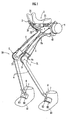
- the walking assisting device includes a seat member 1 serving as a load transfer portion which a user P sits astride and a pair of left and right leg links 2L and 2R attached under the seat member 1.
- the leg links 2L and 2R are each composed of a freely bending and stretching link, which has a first link 4 swingably connected to the undersurface of the seat member 1 via a first joint 3 in the forward/backward direction and a second link 6 connected to the lower end of the first link 4 via a second joint 5.
- the lower end of the second link 6 is connected to a foot attachment portion 8 attached to each of the user's left and right feet via a third joint 7.
- the leg links 2L and 2R are each equipped with a driving source 9 for the second joint 5.
- the driving source 9 is used to rotationally drive the second joint 5 to apply a force in the direction of bending or stretching to each of the leg links 2L and 2R in order to generate bearing power for supporting at least a part of the user's weight (hereinafter, referred to as a weight relief assist force).
- the weight relief assist force generated in each of the leg links 2L and 2R is transmitted to the body of the user P via the seat member 1 and the load on the leg of the user P is thereby reduced.
- a power supply and controller for the driving source 9 are housed in a backpack carried on user's back.
- the user P can use the walking assisting device according to this embodiment only by wearing the foot attachment portions 8 on his feet and sitting on the seat member 1, without having a constrained feeling almost at all.
- the first joints 3 and the first links 4 of the leg links 2L and 2R are located under the crotch of the user P and therefore the user P does not hit his hands against the first joints 3 or the first links 4 when swinging his arms while walking, by which the user P can swing his arms freely.
- the device is small in size and therefore it can be used in a small place, by which the usability is remarkably improved in addition to the reduced constrained feeling and the secured free arm swing.
- the first joints 3 for the leg links 2L and 2R are each composed of a joint member 31 including an arc-shaped guide track 32 longitudinal in the forward/backward direction and a support plate 33 for supporting the guide track 32 as clearly shown in FIG. 4 and FIG. 5 .
- the guide track 32 is composed of an arc-shaped rail in this embodiment, it can also be composed of an arc-shaped groove formed in the support plate 33.
- a slider 41 having vertical pairs of rollers 41a with the guide track 32 vertically interposed therebetween from both sides, so that the slider 41 movably engages with the guide track 32 via the rollers 41.
- leg links 2L and 2R swing in the forward/backward direction around the center of curvature of the guide track 32 and the forward/backward swing fulcrum of the leg links 2L and 2R functions as the center of curvature of the guide track 32.
- the center of curvature of the guide track 32 namely the forward/backward swing fulcrum 3a of each of the leg links 2L and 2R in each first joint 3 is located above the seat member 1. If the user P bends his upper body forward or the like at this moment and thereby the action point of the weight of the upper body of the user P relative to the seat member 1 is misaligned forward of the forward/backward swing fulcrum 3a of each of the leg links 2L and 2R, the seat member 1 inclines forward and downward. If the seat member 1 continues to incline further, it is misaligned backward relative to the user P.
- the action point of the weight is displaced backward under the swing fulcrum 3a together with the forward and downward inclination of the seat member 1 and thereby the forward/backward distance between the fulcrum 3a and the action point of the weight decreases, which thereby decreases the angular moment applied to the seat member 1.
- the angular moment applied to the seat member 1 becomes zero when the action point of the weight is displaced up to the position just under the swing fulcrum 3a, which stabilizes the seat member 1 in this state. Since the seat member 1 automatically converges on the stable state in this way, it is possible to prevent the seat member 1 from being misaligned in the forward/backward direction under the crotch of the user P.
- the slider 41 which is the upper end of each of the leg links 2L and 2R, engages with a part of the guide track 32, which is located backward of a line L1 between the second joint 5 of each of the leg links 2L and 2R and the forward/backward swing fulcrum 3a (the center of curvature of the guide track 32) of each of the leg links 2L and 2R.
- a stopper 32a is attached to each of the forward and backward ends of the guide track 32 in order to prevent the first links 4 from being uncoupled.
- the joint member 31 which is a component of each of the first joint 3 for each of the left and right leg links 2L and 2R, is pivotally supported by forward/backward spindles 35 and 35 supported by a pair of front and back support blocks 34 and 34 attached in the laterally center of the undersurface of the seat member 1, via hinge members 36 and 36 attached to the upper front and back ends of the support plate 33. Therefore, each of the joint members 31 (the first joints 3) is connected to the undersurface of the seat member 1 swingably in the lateral direction. This allows the leg links 2L and 2R to swing in the lateral direction, by which the user P can swing his legs outward.
- joint member 31 for the left leg link 2L and the joint member 31 for the right leg link 2R are pivotally supported by the common spindles 35.
- the lateral swing fulcrum of the first joint 3 for the left leg link 2L and the lateral swing fulcrum of the first joint 3 for the right leg link 2R are located on the same forward/backward axis line.
- the weight of the leg link on the side of the idling leg (the leg with the foot off the floor) (or an assist force if there is generated the assist force for assisting in lifting the idling leg by applying a force to the leg link in the direction of bending it as described later) is applied to the seat member 1 via the lateral swing fulcrum of the first joint 3 for the leg link.
- the seat member 1 is affected by a rolling moment generated around the lateral swing fulcrum of the first joint 3 for the leg link on the side of the supporting leg (the leg with the foot on the floor) due to the weight of the leg link on the side of the idling leg in the one-leg supporting state, which causes the rolling of the seat member 1.
- the lateral swing fulcrum of the first joint 3 for the leg link on the side of the idling leg, to which the weight of the leg link on the side of the idling leg is applied is located on the same axis line (the spindles 35) as one for the lateral swing fulcrum of the first joint 3 for the leg link on the side of the supporting leg in the one-leg supporting state in this embodiment. Therefore, the seat member 1 is not affected by the rolling moment generated around the lateral swing fulcrum of the first joint 3 for the leg link on the side of the supporting leg. Therefore, it is possible to prevent the rolling of the seat member 1 in the one-leg supporting state.
- the weight of the leg link on the side of the idling leg is transmitted to the floor via the leg link on the side of the supporting leg, and the seat member 1 is not affected by the weight of the leg link on the side of the idling leg.
- the leg links 2L and 2R are each formed in such a length that the leg link is bent with the second joint 5 projecting forward of a reference line L2 even if the user P is standing upright, where the reference line L2 (see FIG. 2 ) is a line connecting the forward/backward swing fulcrum 3a of the leg links 2L and 2R in the first joint 3 to the third joint 7.
- the height of the seat member 1 can be automatically adjusted to fit the user P with the control of the driving source 9. Therefore, there is no need to manufacture a dedicated device for an individual or to adjust the lengths of the leg links, thereby achieving a versatile walking assisting device and lowering costs.
- an overhanging portion 42 made of a board member projecting backward, which is opposite to the second joint 5 in the forward/backward direction relative to the reference line L2, to the slider 41 at the end of each of the leg links 2L and 2R on the side of the first joint 3, namely at the upper end of the first link 4, and there is mounted a driving source 9 for the second joint 5 on the overhanging portion 42 as a weight member.
- the driving source 9 functions as a counterweight to reduce the entire swing moment of each of the leg links 2L and 2R including the driving source 9. In consequence, the forward push force applied to the seat member 1 diminishes, too, and thereby the stability is improved.
- the forward swing moment occurs around the forward/backward swing fulcrum 3a due to the weight of the driving source 9 and this moment assists the leg in swinging forward. Therefore, it is possible to eliminate the resistance to the forward swing of the leg, which becomes a problem when the leg links 2L and 2R are bent with the second joints 5 projecting forward of the reference line L2. Additionally the distance between the driving source 9 as a heavy load and the swing fulcrum 3a decreases, which diminishes the moments of inertia of the leg links 2L and 2R around the first joints 3. Therefore, it is possible to prevent the legs of the user P from feeling heavy while walking due to the moments of inertia of the leg links 2L and 2R applied to the legs.
- the driving force generated by the driving source 9 is transmitted to the second joint 5 via driving force transmission means 91.
- the driving force transmission means 91 it is possible to use a parallel linkage with a link connected in parallel to the first link 4 or a hydraulic transmission mechanism with a hydraulic cylinder in a portion apart from the second joint 5 of the second link 6.
- the driving force transmission means 91 is composed of a wire transmission mechanism with a wire 91a between the second joint 5 and the driving source 9 for a reduction in weight and cost.
- two wires 91a are led out from the driving source 9: one wire 91a is paid out from the driving source 9, while the other wire 91a is drawn into the driving source 9.
- the driving source 9 includes an electric motor and a drive pulley for the wire 91a driven by the motor.
- the wires 91a and 91a are passed through two guide tubes 91b and 91b, respectively, provided between a flange 43 formed in the vicinity of the second joint 5 of the first link 4 and the driving source 9.
- a pulley 52 coaxial with a shaft 51 of the second joint 5 is fixed to the second link 6, the two wires 91a and 91a are wound around the pulley 52 in the direction reverse to each other, and the ends of the wires 91a and 91a are fixed to the pulley 52.
- the pulley 52 is rotated by paying out and drawing the wires 91a and 91a from and into the driving source 9, and the rotation causes the second link 6 to swing around the shaft 51 of the second joint 5 relative to the first link 4, thereby bending and stretching the leg links 2L and 2R.
- an arc-shaped groove is formed on the side surface of the pulley 52 and a protruding portion engaging with the groove is formed in the first link 4 in order to limit the swing stroke of the second link 6 relative to the first link 4 to a given range.
- the third joint 7 includes a free joint composed of a yoke 71 connected to the lower end of the second link 6 via a 2-axis force sensor 10 and a moving element 73 connected to a shaft 72 laterally provided at the lower end of the yoke 71 rotatably and also free to tilt axially.
- the weight relief assist force described above acts on the reference line L2 connecting the forward/backward swing fulcrum 3a of the leg links 2L and 2R in the first joint 3 to the third joint 7, when viewed from the lateral perspective.
- An actual weight relief assist force (to be exact, a resultant force between the weight relief assist force and the force generated by the weights of the seat member 1 and the leg links 2L and 2R) acting on the reference line L2 is calculated based on a detected value of the force in the 2-axis direction detected by the force sensor 10.
- the foot attachment portion 8 includes a shoe 81 and a highly rigid armor coupled ring 82 shown in FIG. 6 , which is embedded in the shoe 81.
- a collar 83 is arranged in a standing condition on the upper surface of the coupled ring 82 and the collar 83 is connected to the lower end of the moving element 73 of the third joint 7.
- an elastic plate 84 to be an insole of the shoe 81 is put on the backside of the coupled ring 82.
- On the undersurface of the elastic plate 84 there are mounted a pair of front and back pressure sensors 85 and 85 for detecting loads on the metacarpophalangeal joint (MP joint) and the heel of the user's foot.
- MP joint metacarpophalangeal joint
- the ratio of the load imposed on each foot to the total load on the user's feet is calculated based on the detected values of the pressure sensors 85 and 85 in each of the foot attachment portions 8.
- a control target value for a weight relief assist force that should be generated in each leg link is calculated by multiplying a preset value of the weight relief assist force by the ratio of the load on each foot.
- the driving source 9 is controlled in such a way that an actual weight relief assist force calculated based on the detected value of the force sensor 10 is consistent with the control target value.
- the weight relief assist force of the preset value is generated only with the leg link on the side of the supporting leg.
- the driving of the driving source of the leg link on the side of the idling leg is stopped to allow the second joint 5 to be freely rotated. It is also possible to apply a force in the bending direction to the leg link on the side of the idling leg from the driving source to assist the foot of the idling leg in lifting.
- the weight relief assist force acts on the line connecting the spindle 35 as the lateral swing fulcrum of the first joint 3 to the third joint 7, when viewed from the front. Therefore, a long lateral distance between the spindle 35 and the third joint 7 increases a lateral component of the weight relief assist force and thus increases a lateral force applied on the foot attachment portion 8 and the seat member 1. Therefore, in this embodiment, as shown in FIG. 3 , the collar 83 on the upper surface of the coupled ring 82 is arranged laterally inside so that the third joint 7 is located laterally inside from the center of the width of the foot attachment portion 8. According thereto, the lateral distance between the spindle 35 and the third joint 7 decreases and a smaller lateral force acts on the foot attachment portion 8 and the seat member 1, thereby improving the stability of the foot attachment portion 8 and the seat member 1.
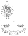
- the seat member 1 as shown in FIG. 7(a) is formed into a shape having a constricted portion 1c, which is narrower in width than the backside 1a and the foreside 1b, in the forward/backward middle of the seat member 1.
- the foreside 1b is curved upward (See FIG. 2 ) and is formed in a fork shape with a lateral middle portion cut away. The user sits on the seat member 1 with his left and right legs positioned laterally on both sides of the constricted portion 1c.
- the wide backside 1a and foreside 1b prevent the seat member 1 from being misaligned relative to the user in the forward/backward direction and the upward curved foreside 1b avoids the leg swinging forward from hitting against the foreside 1b while walking, thereby securing the degree of freedom in leg motion while walking.
- the foreside 1b formed in the fork shape facilitates the foreside 1b to flex laterally. Therefore, even if the forward swinging leg abuts the foreside 1b, the flexion of the foreside 1b absorbs the abutment force and the seat member 1 can be thereby prevented from yawing due to the abutment of the leg.
- the backside 1a has an enough width to receive the user's left and right ischial bones. Accordingly, the weight relief assist force can be reliably transmitted to the user by means of the contact with the ischial bones.
- the seat member 1 includes a core 101 formed of a carbon fiber or the like, a cushioning material 102 put on the upper surface of the core 101, and a cover 103 which covers the core 101 and the cushion material 102.
- the core 101 has a concave 104 in the laterally middle of the core 101 extending in the forward/backward direction as shown in FIG. 7(b) , with the cushion material 102 put on both sides of the concave 104.
- the wall thickness of the outer edge of the core 101 is made thin, so that the abutment forces of the legs from the sides can be flexibly absorbed.
- each leg link can be bent with the second joint projecting backward of the reference line when the user is standing upright.
- each leg link is provided with an overhanging portion which projects forward of the reference line, with a driving source, a battery, or the like mounted as a weight member.
- the first joint 3 includes the arc-shaped guide track 32 and the forward/backward swing fulcrum 3a of each of the leg links 2L and 2R in the first joint 3 is located above the seat member 1 in this embodiment.
- the first joint 3, however, can also be a joint portion having a simple structure with a lateral shaft which pivotally supports the upper end of each of the leg links 2L and 2R so as to be free to swing in the forward/backward direction.
- the load transfer portion can be a waist support belt as has been conventional.
- leg link on the side of the user's handicapped leg of the left and right leg links 2L and 2R in the above embodiment, while omitting the other leg link.
Landscapes
- Engineering & Computer Science (AREA)
- Robotics (AREA)
- Mechanical Engineering (AREA)
- Health & Medical Sciences (AREA)
- Epidemiology (AREA)
- Pain & Pain Management (AREA)
- Physical Education & Sports Medicine (AREA)
- Rehabilitation Therapy (AREA)
- Life Sciences & Earth Sciences (AREA)
- Animal Behavior & Ethology (AREA)
- General Health & Medical Sciences (AREA)
- Public Health (AREA)
- Veterinary Medicine (AREA)
- Rehabilitation Tools (AREA)
- Manipulator (AREA)
- Prostheses (AREA)
Abstract
Description
- The present invention relates to a walking assisting device for assisting walking by reducing load on user's legs.
- Conventionally, as this type of walking assisting device, there is known a device including a load transfer portion and a leg link connected to the load transfer portion, wherein at least a part of the user's weight is supported by the leg link via the load transfer portion to reduce load on a user's leg so as to assist the user in walking (for example, refer to
Japanese Patent Laid-Open No. 2003-220102 - Each leg link is generally formed in a length tailored to the length of a user's leg so that the leg link is stretched when the user is standing upright. This, however, causes a need to manufacture a dedicated device for an individual, which leads to an increase in cost. Therefore, it is desired that the leg links are each formed in such a length that the leg link is bent with the second joint projecting forward or backward of a reference line even if the user is standing upright, where the reference line is defined as a line connecting the forward/backward swing fulcrum of the leg link in the first joint to the third joint. According thereto, the height of the load transfer portion can be automatically adjusted in accordance with the user by controlling the driving source. Therefore, this eliminates the need for manufacturing a dedicated device for an individual, thereby achieving a versatile walking assisting device and lowering costs.
- If the leg link is bent when the user is standing upright, however, the walking assisting device will have the following defects. Specifically, when the user is standing upright, the reference line is substantially vertical. Therefore, if the second joint projects forward of the reference line, the weight of the leg link including the driving source coaxial with the second joint generates a swing moment in a forward tilting direction around the third joint in the leg link, thereby applying a forward push force to the load supporting portion. Furthermore, if the second joint projects backward of the reference line, it generates a swing moment in a backward tilting direction around the third joint in the leg link, thereby applying a backward push force to the load transfer portion.
- The present invention has been provided in view of the above background. Therefore, it is an object of the present invention to provide a walking assisting device capable of improving stability by preventing the push force in the forward/backward direction from being applied to the load transfer portion in spite of using leg links each having such a length that it is bent even if the user is standing upright.
- In order to achieve the above object, according to one aspect of the present invention, there is provided a walking assisting device comprising a load transfer portion and a leg link connected to the load transfer portion via a first joint in such a way as to be swingable in the forward and backward direction, in which at least a part of the user's weight is supported by the leg link via the load transfer portion, the leg link including a freely bending and stretching link having a second joint midway in the vertical direction, with a foot attachment portion attached to a user's foot being connected to the lower end of the leg link via a third joint, and the leg link being formed in such a length that it is bent with the second joint projecting forward or backward of a reference line even if the user is standing upright, where the reference line is defined as a line connecting the forward/backward swing fulcrum of the leg link in the first joint to the third joint; wherein the leg link is provided with an overhanging portion which projects on the side opposite to the second joint in the forward and backward direction relative to the reference line, with a weight member mounted on the overhanging portion.
- When the user is standing upright, the weight of the leg link (excluding the weight member) generates a swing moment in a forward tilting direction (if the second joint projects forward of the reference line) or in a backward tilting direction (if the second joint projects backward of the reference line) around the third joint in the leg link. According to the present invention, however, the weight member is located on the side opposite to the second joint in the forward/backward direction across the reference line, and therefore the weight of the weight member generates a swing moment in the direction reverse to that of the swing moment generated by the weight of the leg link. In other words, the weight member functions as a counterweight, which diminishes the swing moment of the entire leg link including the weight member. As a result, the swing moment reduces the forward/backward push force applied to the load transfer portion, thereby improving the stability.
- If the leg link is bent in such a way that the second joint projects forward of the reference line, a backward swing moment occurs around the forward/backward swing fulcrum in the first joint in the leg link when the user swings his leg forward, thereby giving a resistance to the forward swing of the leg. According to the present invention, however, when the second joint projects forward of the reference line, the overhanging portion projects backward of the reference line. Therefore, the weight of the weight member mounted on the overhanging portion generates a forward swing moment around the forward/backward swing fulcrum in the first joint, and this moment assists the user in swinging his leg forward. Therefore, even if the leg link is bent in such a way that the second joint projects forward of the reference line, there is no resistance given to the forward swing of the leg.
- Meanwhile, if the moment of inertia of the leg link around the first joint increases, the user's leg feels heavy while walking due to the moment of inertia of the leg link applied to the leg. In this case, the overhanging portion is provided at the end of the leg link on the side of the first joint, which reduces the distance between the weight member mounted on the overhanging portion and the first joint. Therefore, it is possible to reduce the moment of inertia of the leg link around the first joint and to thereby facilitate walking.
- The weight member preferably includes a driving source for the second joint. More specifically, the driving source for the second joint is mounted on the leg link from the beginning. Using the driving source serving as the weight member prevents an increase in the weight of the leg link rationally. In this case, the driving force generated by the driving source is transmitted to the second joint via driving force transmission means.
- The driving force transmission means preferably includes a wire transmission mechanism with a wire between the second joint and the driving source. Note here that the driving force transmission means can be a linkage with a parallel link or a hydraulic transmission mechanism with a hydraulic cylinder. The wire transmission mechanism, however, is more advantageous because it can reduce the weight and cost.
-
-
FIG. 1 is a perspective diagram of a walking assisting device according to an embodiment of the present invention; -
FIG. 2 is a side view of the walking assisting device according to the embodiment; -
FIG. 3 is a front view of the walking assisting device according to the embodiment; -
FIG. 4 is a fragmentary perspective diagram of first joints of the walking assisting device according to the embodiment; -
FIG. 5 is a fragmentary side view of the first joint of the walking assisting device according to the embodiment; -
FIG. 6 is a perspective diagram of a lower end of a leg link of the walking assisting device according to the embodiment; and -
FIG. 7(a) is a perspective diagram of a seat member of the walking assisting device according to the embodiment andFIG. 7(b) is a perspective diagram of a core of the seat member. - A walking assisting device according to an embodiment of the present invention will be described hereinafter. As shown in
FIG. 1 to FIG. 3 , the walking assisting device includes a seat member 1 serving as a load transfer portion which a user P sits astride and a pair of left andright leg links - The
leg links first link 4 swingably connected to the undersurface of the seat member 1 via afirst joint 3 in the forward/backward direction and asecond link 6 connected to the lower end of thefirst link 4 via asecond joint 5. In addition, the lower end of thesecond link 6 is connected to afoot attachment portion 8 attached to each of the user's left and right feet via athird joint 7. Furthermore, theleg links driving source 9 for thesecond joint 5. Then, thedriving source 9 is used to rotationally drive thesecond joint 5 to apply a force in the direction of bending or stretching to each of theleg links leg links driving source 9 are housed in a backpack carried on user's back. - The user P can use the walking assisting device according to this embodiment only by wearing the
foot attachment portions 8 on his feet and sitting on the seat member 1, without having a constrained feeling almost at all. In addition, thefirst joints 3 and thefirst links 4 of theleg links first joints 3 or thefirst links 4 when swinging his arms while walking, by which the user P can swing his arms freely. Moreover, the device is small in size and therefore it can be used in a small place, by which the usability is remarkably improved in addition to the reduced constrained feeling and the secured free arm swing. - The
first joints 3 for theleg links joint member 31 including an arc-shaped guide track 32 longitudinal in the forward/backward direction and asupport plate 33 for supporting theguide track 32 as clearly shown inFIG. 4 and FIG. 5 . While theguide track 32 is composed of an arc-shaped rail in this embodiment, it can also be composed of an arc-shaped groove formed in thesupport plate 33. At the upper end of thefirst link 4 of each of theleg links slider 41 having vertical pairs ofrollers 41a with theguide track 32 vertically interposed therebetween from both sides, so that theslider 41 movably engages with theguide track 32 via therollers 41. In this way, the leg links 2L and 2R swing in the forward/backward direction around the center of curvature of theguide track 32 and the forward/backward swing fulcrum of theleg links guide track 32. - As shown in
FIG. 2 , the center of curvature of theguide track 32, namely the forward/backward swing fulcrum 3a of each of theleg links first joint 3 is located above the seat member 1. If the user P bends his upper body forward or the like at this moment and thereby the action point of the weight of the upper body of the user P relative to the seat member 1 is misaligned forward of the forward/backward swing fulcrum 3a of each of theleg links - In addition, the
slider 41, which is the upper end of each of theleg links guide track 32, which is located backward of a line L1 between thesecond joint 5 of each of theleg links leg links leg links guide track 32 particularly long in the forward direction. In addition, astopper 32a is attached to each of the forward and backward ends of theguide track 32 in order to prevent thefirst links 4 from being uncoupled. - Furthermore, the
joint member 31, which is a component of each of the first joint 3 for each of the left andright leg links backward spindles hinge members support plate 33. Therefore, each of the joint members 31 (the first joints 3) is connected to the undersurface of the seat member 1 swingably in the lateral direction. This allows theleg links - Furthermore, the
joint member 31 for theleft leg link 2L and thejoint member 31 for theright leg link 2R are pivotally supported by thecommon spindles 35. In other words, the lateral swing fulcrum of the first joint 3 for theleft leg link 2L and the lateral swing fulcrum of the first joint 3 for theright leg link 2R are located on the same forward/backward axis line. In a one-leg supporting state, the weight of the leg link on the side of the idling leg (the leg with the foot off the floor) (or an assist force if there is generated the assist force for assisting in lifting the idling leg by applying a force to the leg link in the direction of bending it as described later) is applied to the seat member 1 via the lateral swing fulcrum of the first joint 3 for the leg link. If the lateral swing fulcrum of the first joint 3 for theleft leg link 2L is displaced from the lateral swing fulcrum of the first joint 3 for the right leg link, the seat member 1 is affected by a rolling moment generated around the lateral swing fulcrum of the first joint 3 for the leg link on the side of the supporting leg (the leg with the foot on the floor) due to the weight of the leg link on the side of the idling leg in the one-leg supporting state, which causes the rolling of the seat member 1. - On the other hand, the lateral swing fulcrum of the first joint 3 for the leg link on the side of the idling leg, to which the weight of the leg link on the side of the idling leg is applied, is located on the same axis line (the spindles 35) as one for the lateral swing fulcrum of the first joint 3 for the leg link on the side of the supporting leg in the one-leg supporting state in this embodiment. Therefore, the seat member 1 is not affected by the rolling moment generated around the lateral swing fulcrum of the first joint 3 for the leg link on the side of the supporting leg. Therefore, it is possible to prevent the rolling of the seat member 1 in the one-leg supporting state. The weight of the leg link on the side of the idling leg is transmitted to the floor via the leg link on the side of the supporting leg, and the seat member 1 is not affected by the weight of the leg link on the side of the idling leg.
- Moreover, the
leg links FIG. 2 ) is a line connecting the forward/backward swing fulcrum 3a of theleg links third joint 7. In addition, the height of the seat member 1 can be automatically adjusted to fit the user P with the control of the drivingsource 9. Therefore, there is no need to manufacture a dedicated device for an individual or to adjust the lengths of the leg links, thereby achieving a versatile walking assisting device and lowering costs. - In the upright state of the user P, the reference line L2 is almost vertical at this moment and almost all parts of each of the
leg links third joint 7. Therefore, if the drivingsource 9 is placed on the same axis as thesecond joint 5, the weight of each of theleg links driving sources 9 generates a large swing moment in a forward tilting direction around the third joint 7 in each of theleg links leg links source 9 is placed on the same axis as thesecond joint 5, the moment of inertia of each of theleg links leg links - Therefore, in this embodiment, there is attached an overhanging
portion 42 made of a board member projecting backward, which is opposite to the second joint 5 in the forward/backward direction relative to the reference line L2, to theslider 41 at the end of each of theleg links first link 4, and there is mounted a drivingsource 9 for the second joint 5 on the overhangingportion 42 as a weight member. Thereby, when the user P is standing upright, the reverse swing moment generated by the weight of the drivingsource 9 diminishes the swing moment in the forward tilting direction around the third joint 7 generated in each of theleg links leg links source 9. More specifically, the drivingsource 9 functions as a counterweight to reduce the entire swing moment of each of theleg links source 9. In consequence, the forward push force applied to the seat member 1 diminishes, too, and thereby the stability is improved. - Furthermore, when the user P swings his leg forward, the forward swing moment occurs around the forward/backward swing fulcrum 3a due to the weight of the driving
source 9 and this moment assists the leg in swinging forward. Therefore, it is possible to eliminate the resistance to the forward swing of the leg, which becomes a problem when theleg links second joints 5 projecting forward of the reference line L2. Additionally the distance between the drivingsource 9 as a heavy load and the swing fulcrum 3a decreases, which diminishes the moments of inertia of theleg links first joints 3. Therefore, it is possible to prevent the legs of the user P from feeling heavy while walking due to the moments of inertia of theleg links - The driving force generated by the driving
source 9 is transmitted to thesecond joint 5 via driving force transmission means 91. As the driving force transmission means 91, it is possible to use a parallel linkage with a link connected in parallel to thefirst link 4 or a hydraulic transmission mechanism with a hydraulic cylinder in a portion apart from thesecond joint 5 of thesecond link 6. In this embodiment, however, the driving force transmission means 91 is composed of a wire transmission mechanism with awire 91a between thesecond joint 5 and the drivingsource 9 for a reduction in weight and cost. - The details thereof are as described below. More specifically, two
wires 91a are led out from the driving source 9: onewire 91a is paid out from the drivingsource 9, while theother wire 91a is drawn into the drivingsource 9. The drivingsource 9 includes an electric motor and a drive pulley for thewire 91a driven by the motor. Thewires guide tubes flange 43 formed in the vicinity of thesecond joint 5 of thefirst link 4 and the drivingsource 9. Additionally, apulley 52 coaxial with ashaft 51 of thesecond joint 5 is fixed to thesecond link 6, the twowires pulley 52 in the direction reverse to each other, and the ends of thewires pulley 52. In this way, thepulley 52 is rotated by paying out and drawing thewires source 9, and the rotation causes thesecond link 6 to swing around theshaft 51 of the second joint 5 relative to thefirst link 4, thereby bending and stretching theleg links pulley 52 and a protruding portion engaging with the groove is formed in thefirst link 4 in order to limit the swing stroke of thesecond link 6 relative to thefirst link 4 to a given range. - As shown in
FIG. 6 , the third joint 7 includes a free joint composed of ayoke 71 connected to the lower end of thesecond link 6 via a 2-axis force sensor 10 and a movingelement 73 connected to ashaft 72 laterally provided at the lower end of theyoke 71 rotatably and also free to tilt axially. The weight relief assist force described above acts on the reference line L2 connecting the forward/backward swing fulcrum 3a of theleg links leg links force sensor 10. - The
foot attachment portion 8 includes ashoe 81 and a highly rigid armor coupledring 82 shown inFIG. 6 , which is embedded in theshoe 81. Acollar 83 is arranged in a standing condition on the upper surface of the coupledring 82 and thecollar 83 is connected to the lower end of the movingelement 73 of thethird joint 7. Furthermore, as shown inFIG. 2 , anelastic plate 84 to be an insole of theshoe 81 is put on the backside of the coupledring 82. On the undersurface of theelastic plate 84, there are mounted a pair of front andback pressure sensors - To control each of the
leg links pressure sensors foot attachment portions 8. Subsequently, a control target value for a weight relief assist force that should be generated in each leg link is calculated by multiplying a preset value of the weight relief assist force by the ratio of the load on each foot. Thereafter, the drivingsource 9 is controlled in such a way that an actual weight relief assist force calculated based on the detected value of theforce sensor 10 is consistent with the control target value. In the one-leg supporting state, the weight relief assist force of the preset value is generated only with the leg link on the side of the supporting leg. In this instance, the driving of the driving source of the leg link on the side of the idling leg is stopped to allow the second joint 5 to be freely rotated. It is also possible to apply a force in the bending direction to the leg link on the side of the idling leg from the driving source to assist the foot of the idling leg in lifting. - The weight relief assist force acts on the line connecting the
spindle 35 as the lateral swing fulcrum of the first joint 3 to the third joint 7, when viewed from the front. Therefore, a long lateral distance between thespindle 35 and the third joint 7 increases a lateral component of the weight relief assist force and thus increases a lateral force applied on thefoot attachment portion 8 and the seat member 1. Therefore, in this embodiment, as shown inFIG. 3 , thecollar 83 on the upper surface of the coupledring 82 is arranged laterally inside so that the third joint 7 is located laterally inside from the center of the width of thefoot attachment portion 8. According thereto, the lateral distance between thespindle 35 and the third joint 7 decreases and a smaller lateral force acts on thefoot attachment portion 8 and the seat member 1, thereby improving the stability of thefoot attachment portion 8 and the seat member 1. - While various kinds of things have been done to stabilize the seat member 1 as described above, some thought is also put into the seat member 1 itself in this embodiment. The thought will be described in detail hereinafter. The seat member 1 as shown in
FIG. 7(a) is formed into a shape having a constricted portion 1c, which is narrower in width than the backside 1a and the foreside 1b, in the forward/backward middle of the seat member 1. The foreside 1b is curved upward (SeeFIG. 2 ) and is formed in a fork shape with a lateral middle portion cut away. The user sits on the seat member 1 with his left and right legs positioned laterally on both sides of the constricted portion 1c. According thereto, the wide backside 1a and foreside 1b prevent the seat member 1 from being misaligned relative to the user in the forward/backward direction and the upward curved foreside 1b avoids the leg swinging forward from hitting against the foreside 1b while walking, thereby securing the degree of freedom in leg motion while walking. Furthermore, the foreside 1b formed in the fork shape facilitates the foreside 1b to flex laterally. Therefore, even if the forward swinging leg abuts the foreside 1b, the flexion of the foreside 1b absorbs the abutment force and the seat member 1 can be thereby prevented from yawing due to the abutment of the leg. In addition, the user's crotch or the like does not abut the foreside 1b and therefore the seat member 1 becomes comfortable to sit in. The backside 1a has an enough width to receive the user's left and right ischial bones. Accordingly, the weight relief assist force can be reliably transmitted to the user by means of the contact with the ischial bones. - The seat member 1 includes a core 101 formed of a carbon fiber or the like, a
cushioning material 102 put on the upper surface of thecore 101, and acover 103 which covers thecore 101 and thecushion material 102. Thecore 101 has a concave 104 in the laterally middle of thecore 101 extending in the forward/backward direction as shown inFIG. 7(b) , with thecushion material 102 put on both sides of the concave 104. In addition, the wall thickness of the outer edge of thecore 101 is made thin, so that the abutment forces of the legs from the sides can be flexibly absorbed. - Although the preferred embodiment of the present invention has been described hereinabove with reference to attached drawings, the present invention is not limited to the above embodiment. For example, it is also possible to dispose the driving
source 9 coaxially with the second joint 5 with a heavy load such as a battery mounted as a weight member on the overhangingportion 42. Moreover, each leg link can be bent with the second joint projecting backward of the reference line when the user is standing upright. In this case, each leg link is provided with an overhanging portion which projects forward of the reference line, with a driving source, a battery, or the like mounted as a weight member. Furthermore, the first joint 3 includes the arc-shapedguide track 32 and the forward/backward swing fulcrum 3a of each of theleg links leg links right leg links
Claims (5)
- A walking assisting device comprising a load transfer portion and a leg link connected to the load transfer portion via a first joint in such a way as to be swingable in the forward and backward direction, in which at least a part of the user's weight is supported by the leg link via the load transfer portion,
the leg link including a freely bending and stretching link having a second joint midway in the vertical direction, with a foot attachment portion attached to a user's foot being connected to the lower end of the leg link via a third joint, and the leg link being formed in such a length that it is bent with the second joint projecting forward or backward of a reference line even if the user is standing upright, where the reference line is defined as a line connecting the forward/backward swing fulcrum of the leg link in the first joint to the third joint;
wherein the leg link is provided with an overhanging portion which projects on the side opposite to the second joint in the forward and backward direction relative to the reference line, with a weight member mounted on the overhanging portion. - The walking assisting device according to claim 1, wherein the second joint projects forward of the reference line and the overhanging portion projects backward of the reference line.
- The walking assisting device according to claim 1, wherein the overhanging portion is provided at the end of the leg link on the side of the first joint.
- The walking assisting device according to claim 1, wherein the weight member includes a driving source for the second joint and a driving force generated by the driving source is transmitted to the second joint via a driving force transmission means.
- The walking assisting device according to claim 4, wherein the driving force transmission means includes a wire transmission mechanism with a wire between the second joint and the driving source.
Applications Claiming Priority (3)
| Application Number | Priority Date | Filing Date | Title |
|---|---|---|---|
| JP2005155329 | 2005-05-27 | ||
| JP2005220856A JP4387996B2 (en) | 2005-07-29 | 2005-07-29 | Walking assist device |
| PCT/JP2006/310656 WO2006126709A1 (en) | 2005-05-27 | 2006-05-29 | Walking assistance device |
Publications (3)
| Publication Number | Publication Date |
|---|---|
| EP1905407A1 true EP1905407A1 (en) | 2008-04-02 |
| EP1905407A4 EP1905407A4 (en) | 2008-09-03 |
| EP1905407B1 EP1905407B1 (en) | 2010-07-21 |
Family
ID=37452122
Family Applications (1)
| Application Number | Title | Priority Date | Filing Date |
|---|---|---|---|
| EP06746934A Not-in-force EP1905407B1 (en) | 2005-05-27 | 2006-05-29 | Walking assistance device |
Country Status (8)
| Country | Link |
|---|---|
| US (1) | US8002719B2 (en) |
| EP (1) | EP1905407B1 (en) |
| KR (1) | KR100856847B1 (en) |
| BR (1) | BRPI0607422A2 (en) |
| CA (1) | CA2598091C (en) |
| DE (1) | DE602006015649D1 (en) |
| RU (1) | RU2389469C2 (en) |
| WO (1) | WO2006126709A1 (en) |
Cited By (1)
| Publication number | Priority date | Publication date | Assignee | Title |
|---|---|---|---|---|
| WO2018122331A1 (en) * | 2016-12-29 | 2018-07-05 | Safran Electronics & Defense | Exoskeleton sub-assembly and exoskeleton structure including such a sub-assembly |
Families Citing this family (19)
| Publication number | Priority date | Publication date | Assignee | Title |
|---|---|---|---|---|
| JP5083461B2 (en) | 2010-06-21 | 2012-11-28 | トヨタ自動車株式会社 | Leg support device |
| US8418705B2 (en) * | 2010-07-30 | 2013-04-16 | Toyota Motor Engineering & Manufacturing North America, Inc. | Robotic cane devices |
| US11400010B2 (en) * | 2011-07-29 | 2022-08-02 | Leonis Medical Corporation | Method and system for control and operation of motorized orthotic exoskeleton joints |
| JP5636352B2 (en) * | 2011-10-24 | 2014-12-03 | 本田技研工業株式会社 | Motion assist device and walking assist device |
| RU2493805C1 (en) * | 2012-02-20 | 2013-09-27 | Вячеслав Геннадьевич Иванов | Exoskeleton of disabled person |
| CA2902577C (en) | 2013-03-14 | 2019-06-11 | Ekso Bionics, Inc. | Non-anthropomorphic hip joint locations for exoskeletons |
| KR101497673B1 (en) * | 2013-12-02 | 2015-03-03 | 경북대학교 산학협력단 | two-leg walking assistant system for boarding type |
| US10231859B1 (en) | 2014-05-01 | 2019-03-19 | Boston Dynamics, Inc. | Brace system |
| JP6386269B2 (en) * | 2014-06-30 | 2018-09-05 | 本田技研工業株式会社 | Walking assist device |
| RU2567589C1 (en) * | 2014-08-05 | 2015-11-10 | Вячеслав Геннадьевич Иванов | Exoskeleton |
| KR102330670B1 (en) | 2014-08-07 | 2021-11-24 | 삼성전자주식회사 | Link assembly and leg supporting apparatus using the same |
| KR101621414B1 (en) * | 2014-11-11 | 2016-05-23 | 울산과학기술원 | Cable-Driven Ankle Rehabilitation System |
| JP6284878B2 (en) * | 2014-12-26 | 2018-02-28 | 本田技研工業株式会社 | Joint power control device |
| JP6293653B2 (en) * | 2014-12-26 | 2018-03-14 | 本田技研工業株式会社 | Elastic force generator |
| CN107427679B (en) * | 2015-01-26 | 2021-08-24 | Cy医药整形外科股份有限公司 | Patient treatment systems and methods |
| US10307319B2 (en) * | 2015-03-04 | 2019-06-04 | Bonutti Research, Inc. | Orthosis for range of motion |
| EP3158893B1 (en) * | 2015-10-21 | 2021-04-28 | noonee AG | Seat unit for wearable sitting posture assisting device |
| EP3241531A1 (en) * | 2016-05-04 | 2017-11-08 | noonee AG | Leg unit for a wearable sitting posture assisting device |
| CN116729520B (en) * | 2023-08-11 | 2023-10-20 | 太原理工大学 | Bionic four-foot robot based on double-layer corrugated pipe pneumatic soft driver |
Family Cites Families (8)
| Publication number | Priority date | Publication date | Assignee | Title |
|---|---|---|---|---|
| FR2589360B1 (en) * | 1985-10-30 | 1987-12-24 | Chareire Jean Louis | APPARATUS FOR MECHANICAL ASSISTANCE OF LEG PROPULSION |
| JP3156367B2 (en) | 1992-06-02 | 2001-04-16 | 株式会社日立製作所 | Walking assistance device |
| IL105034A (en) * | 1993-03-12 | 1998-03-10 | Sate Of Israel Ministry Of Def | Exoskeletal system |
| US5476441A (en) * | 1993-09-30 | 1995-12-19 | Massachusetts Institute Of Technology | Controlled-brake orthosis |
| RU2118147C1 (en) * | 1994-06-29 | 1998-08-27 | Анатолий Гералевич Жуков | Device designed to facilitate walking and carrying loads |
| JP2000166997A (en) * | 1998-12-10 | 2000-06-20 | Nsk Ltd | Walking aid |
| JP3917432B2 (en) | 2002-01-29 | 2007-05-23 | 株式会社日立製作所 | Operation support device |
| RU58911U1 (en) * | 2006-07-20 | 2006-12-10 | Региональный Благотворительный Фонд "Реабилитация Ребенка. Центр Г.Н. Романова" | MODULAR ORTHOPEDIC APPARATUS |
-
2006
- 2006-05-29 WO PCT/JP2006/310656 patent/WO2006126709A1/en not_active Ceased
- 2006-05-29 RU RU2007148517/14A patent/RU2389469C2/en not_active IP Right Cessation
- 2006-05-29 KR KR1020077020248A patent/KR100856847B1/en not_active Expired - Fee Related
- 2006-05-29 EP EP06746934A patent/EP1905407B1/en not_active Not-in-force
- 2006-05-29 CA CA2598091A patent/CA2598091C/en not_active Expired - Fee Related
- 2006-05-29 US US11/908,571 patent/US8002719B2/en not_active Expired - Fee Related
- 2006-05-29 DE DE602006015649T patent/DE602006015649D1/en active Active
- 2006-05-29 BR BRPI0607422-7A patent/BRPI0607422A2/en not_active IP Right Cessation
Cited By (6)
| Publication number | Priority date | Publication date | Assignee | Title |
|---|---|---|---|---|
| WO2018122331A1 (en) * | 2016-12-29 | 2018-07-05 | Safran Electronics & Defense | Exoskeleton sub-assembly and exoskeleton structure including such a sub-assembly |
| FR3061427A1 (en) * | 2016-12-29 | 2018-07-06 | Safran Electronics & Defense | EXOSQUELET AND EXOSQUELETTE STRUCTURE SUB-ASSEMBLY INCLUDING SUCH A SUBSET |
| AU2017387838B2 (en) * | 2016-12-29 | 2019-08-29 | B-Temia Inc. | Exoskeleton sub-assembly and exoskeleton structure including such a sub-assembly |
| CN110300643A (en) * | 2016-12-29 | 2019-10-01 | 赛峰电子与防务公司 | Ectoskeleton sub-component and ectoskeleton structure including this subassemblies |
| CN110300643B (en) * | 2016-12-29 | 2020-08-21 | 赛峰电子与防务公司 | Exoskeleton subassembly and exoskeleton structure including such subassembly |
| US10850388B2 (en) | 2016-12-29 | 2020-12-01 | Safran Electronics & Defense | Exoskeleton sub-assembly and exoskeleton structure including such a sub-assembly |
Also Published As
| Publication number | Publication date |
|---|---|
| US8002719B2 (en) | 2011-08-23 |
| KR100856847B1 (en) | 2008-09-05 |
| EP1905407B1 (en) | 2010-07-21 |
| CA2598091C (en) | 2011-04-12 |
| KR20070110061A (en) | 2007-11-15 |
| RU2007148517A (en) | 2009-07-10 |
| CA2598091A1 (en) | 2006-11-30 |
| US20080289670A1 (en) | 2008-11-27 |
| EP1905407A4 (en) | 2008-09-03 |
| DE602006015649D1 (en) | 2010-09-02 |
| BRPI0607422A2 (en) | 2009-09-08 |
| WO2006126709A1 (en) | 2006-11-30 |
| RU2389469C2 (en) | 2010-05-20 |
Similar Documents
| Publication | Publication Date | Title |
|---|---|---|
| US7731673B2 (en) | Walking assisting device | |
| EP1905408B1 (en) | Walking assisting device | |
| EP1905407B1 (en) | Walking assistance device | |
| EP2055287B1 (en) | Walking assistance device | |
| CN101119696B (en) | Walking assisting device | |
| JP4641225B2 (en) | Walking assist device | |
| CA2661364C (en) | Walking assist device | |
| US8083702B2 (en) | Walking assistance device | |
| JP4387996B2 (en) | Walking assist device | |
| JP5285576B2 (en) | Walking assist device |
Legal Events
| Date | Code | Title | Description |
|---|---|---|---|
| PUAI | Public reference made under article 153(3) epc to a published international application that has entered the european phase |
Free format text: ORIGINAL CODE: 0009012 |
|
| 17P | Request for examination filed |
Effective date: 20071221 |
|
| AK | Designated contracting states |
Kind code of ref document: A1 Designated state(s): AT BE BG CH CY CZ DE DK EE ES FI FR GB GR HU IE IS IT LI LT LU LV MC NL PL PT RO SE SI SK TR |
|
| A4 | Supplementary search report drawn up and despatched |
Effective date: 20080805 |
|
| DAX | Request for extension of the european patent (deleted) | ||
| RIC1 | Information provided on ipc code assigned before grant |
Ipc: A61H 3/00 20060101AFI20061208BHEP Ipc: B25J 9/00 20060101ALI20080730BHEP |
|
| 17Q | First examination report despatched |
Effective date: 20080828 |
|
| GRAP | Despatch of communication of intention to grant a patent |
Free format text: ORIGINAL CODE: EPIDOSNIGR1 |
|
| GRAS | Grant fee paid |
Free format text: ORIGINAL CODE: EPIDOSNIGR3 |
|
| GRAA | (expected) grant |
Free format text: ORIGINAL CODE: 0009210 |
|
| AK | Designated contracting states |
Kind code of ref document: B1 Designated state(s): AT BE BG CH CY CZ DE DK EE ES FI FR GB GR HU IE IS IT LI LT LU LV MC NL PL PT RO SE SI SK TR |
|
| REG | Reference to a national code |
Ref country code: GB Ref legal event code: FG4D |
|
| REG | Reference to a national code |
Ref country code: CH Ref legal event code: EP |
|
| REG | Reference to a national code |
Ref country code: IE Ref legal event code: FG4D |
|
| REF | Corresponds to: |
Ref document number: 602006015649 Country of ref document: DE Date of ref document: 20100902 Kind code of ref document: P |
|
| REG | Reference to a national code |
Ref country code: NL Ref legal event code: VDEP Effective date: 20100721 |
|
| LTIE | Lt: invalidation of european patent or patent extension |
Effective date: 20100721 |
|
| PG25 | Lapsed in a contracting state [announced via postgrant information from national office to epo] |
Ref country code: NL Free format text: LAPSE BECAUSE OF FAILURE TO SUBMIT A TRANSLATION OF THE DESCRIPTION OR TO PAY THE FEE WITHIN THE PRESCRIBED TIME-LIMIT Effective date: 20100721 Ref country code: FI Free format text: LAPSE BECAUSE OF FAILURE TO SUBMIT A TRANSLATION OF THE DESCRIPTION OR TO PAY THE FEE WITHIN THE PRESCRIBED TIME-LIMIT Effective date: 20100721 Ref country code: AT Free format text: LAPSE BECAUSE OF FAILURE TO SUBMIT A TRANSLATION OF THE DESCRIPTION OR TO PAY THE FEE WITHIN THE PRESCRIBED TIME-LIMIT Effective date: 20100721 Ref country code: LT Free format text: LAPSE BECAUSE OF FAILURE TO SUBMIT A TRANSLATION OF THE DESCRIPTION OR TO PAY THE FEE WITHIN THE PRESCRIBED TIME-LIMIT Effective date: 20100721 |
|
| PG25 | Lapsed in a contracting state [announced via postgrant information from national office to epo] |
Ref country code: CY Free format text: LAPSE BECAUSE OF FAILURE TO SUBMIT A TRANSLATION OF THE DESCRIPTION OR TO PAY THE FEE WITHIN THE PRESCRIBED TIME-LIMIT Effective date: 20100721 Ref country code: PL Free format text: LAPSE BECAUSE OF FAILURE TO SUBMIT A TRANSLATION OF THE DESCRIPTION OR TO PAY THE FEE WITHIN THE PRESCRIBED TIME-LIMIT Effective date: 20100721 Ref country code: BG Free format text: LAPSE BECAUSE OF FAILURE TO SUBMIT A TRANSLATION OF THE DESCRIPTION OR TO PAY THE FEE WITHIN THE PRESCRIBED TIME-LIMIT Effective date: 20101021 Ref country code: SI Free format text: LAPSE BECAUSE OF FAILURE TO SUBMIT A TRANSLATION OF THE DESCRIPTION OR TO PAY THE FEE WITHIN THE PRESCRIBED TIME-LIMIT Effective date: 20100721 Ref country code: PT Free format text: LAPSE BECAUSE OF FAILURE TO SUBMIT A TRANSLATION OF THE DESCRIPTION OR TO PAY THE FEE WITHIN THE PRESCRIBED TIME-LIMIT Effective date: 20101122 Ref country code: IS Free format text: LAPSE BECAUSE OF FAILURE TO SUBMIT A TRANSLATION OF THE DESCRIPTION OR TO PAY THE FEE WITHIN THE PRESCRIBED TIME-LIMIT Effective date: 20101121 |
|
| PG25 | Lapsed in a contracting state [announced via postgrant information from national office to epo] |
Ref country code: GR Free format text: LAPSE BECAUSE OF FAILURE TO SUBMIT A TRANSLATION OF THE DESCRIPTION OR TO PAY THE FEE WITHIN THE PRESCRIBED TIME-LIMIT Effective date: 20101022 Ref country code: BE Free format text: LAPSE BECAUSE OF FAILURE TO SUBMIT A TRANSLATION OF THE DESCRIPTION OR TO PAY THE FEE WITHIN THE PRESCRIBED TIME-LIMIT Effective date: 20100721 Ref country code: SE Free format text: LAPSE BECAUSE OF FAILURE TO SUBMIT A TRANSLATION OF THE DESCRIPTION OR TO PAY THE FEE WITHIN THE PRESCRIBED TIME-LIMIT Effective date: 20100721 Ref country code: LV Free format text: LAPSE BECAUSE OF FAILURE TO SUBMIT A TRANSLATION OF THE DESCRIPTION OR TO PAY THE FEE WITHIN THE PRESCRIBED TIME-LIMIT Effective date: 20100721 |
|
| PG25 | Lapsed in a contracting state [announced via postgrant information from national office to epo] |
Ref country code: DK Free format text: LAPSE BECAUSE OF FAILURE TO SUBMIT A TRANSLATION OF THE DESCRIPTION OR TO PAY THE FEE WITHIN THE PRESCRIBED TIME-LIMIT Effective date: 20100721 |
|
| PLBE | No opposition filed within time limit |
Free format text: ORIGINAL CODE: 0009261 |
|
| STAA | Information on the status of an ep patent application or granted ep patent |
Free format text: STATUS: NO OPPOSITION FILED WITHIN TIME LIMIT |
|
| PG25 | Lapsed in a contracting state [announced via postgrant information from national office to epo] |
Ref country code: EE Free format text: LAPSE BECAUSE OF FAILURE TO SUBMIT A TRANSLATION OF THE DESCRIPTION OR TO PAY THE FEE WITHIN THE PRESCRIBED TIME-LIMIT Effective date: 20100721 Ref country code: RO Free format text: LAPSE BECAUSE OF FAILURE TO SUBMIT A TRANSLATION OF THE DESCRIPTION OR TO PAY THE FEE WITHIN THE PRESCRIBED TIME-LIMIT Effective date: 20100721 Ref country code: SK Free format text: LAPSE BECAUSE OF FAILURE TO SUBMIT A TRANSLATION OF THE DESCRIPTION OR TO PAY THE FEE WITHIN THE PRESCRIBED TIME-LIMIT Effective date: 20100721 Ref country code: CZ Free format text: LAPSE BECAUSE OF FAILURE TO SUBMIT A TRANSLATION OF THE DESCRIPTION OR TO PAY THE FEE WITHIN THE PRESCRIBED TIME-LIMIT Effective date: 20100721 Ref country code: IT Free format text: LAPSE BECAUSE OF FAILURE TO SUBMIT A TRANSLATION OF THE DESCRIPTION OR TO PAY THE FEE WITHIN THE PRESCRIBED TIME-LIMIT Effective date: 20100721 |
|
| 26N | No opposition filed |
Effective date: 20110426 |
|
| PG25 | Lapsed in a contracting state [announced via postgrant information from national office to epo] |
Ref country code: ES Free format text: LAPSE BECAUSE OF FAILURE TO SUBMIT A TRANSLATION OF THE DESCRIPTION OR TO PAY THE FEE WITHIN THE PRESCRIBED TIME-LIMIT Effective date: 20101101 |
|
| REG | Reference to a national code |
Ref country code: DE Ref legal event code: R097 Ref document number: 602006015649 Country of ref document: DE Effective date: 20110426 |
|
| PGFP | Annual fee paid to national office [announced via postgrant information from national office to epo] |
Ref country code: GB Payment date: 20110516 Year of fee payment: 6 |
|
| PG25 | Lapsed in a contracting state [announced via postgrant information from national office to epo] |
Ref country code: MC Free format text: LAPSE BECAUSE OF NON-PAYMENT OF DUE FEES Effective date: 20110531 |
|
| REG | Reference to a national code |
Ref country code: CH Ref legal event code: PL |
|
| PG25 | Lapsed in a contracting state [announced via postgrant information from national office to epo] |
Ref country code: LI Free format text: LAPSE BECAUSE OF NON-PAYMENT OF DUE FEES Effective date: 20110531 Ref country code: CH Free format text: LAPSE BECAUSE OF NON-PAYMENT OF DUE FEES Effective date: 20110531 |
|
| REG | Reference to a national code |
Ref country code: FR Ref legal event code: ST Effective date: 20120131 |
|
| REG | Reference to a national code |
Ref country code: IE Ref legal event code: MM4A |
|
| PG25 | Lapsed in a contracting state [announced via postgrant information from national office to epo] |
Ref country code: IE Free format text: LAPSE BECAUSE OF NON-PAYMENT OF DUE FEES Effective date: 20110529 Ref country code: FR Free format text: LAPSE BECAUSE OF NON-PAYMENT OF DUE FEES Effective date: 20110531 |
|
| GBPC | Gb: european patent ceased through non-payment of renewal fee |
Effective date: 20120529 |
|
| PG25 | Lapsed in a contracting state [announced via postgrant information from national office to epo] |
Ref country code: GB Free format text: LAPSE BECAUSE OF NON-PAYMENT OF DUE FEES Effective date: 20120529 |
|
| PG25 | Lapsed in a contracting state [announced via postgrant information from national office to epo] |
Ref country code: LU Free format text: LAPSE BECAUSE OF NON-PAYMENT OF DUE FEES Effective date: 20110529 |
|
| PG25 | Lapsed in a contracting state [announced via postgrant information from national office to epo] |
Ref country code: TR Free format text: LAPSE BECAUSE OF FAILURE TO SUBMIT A TRANSLATION OF THE DESCRIPTION OR TO PAY THE FEE WITHIN THE PRESCRIBED TIME-LIMIT Effective date: 20100721 |
|
| PG25 | Lapsed in a contracting state [announced via postgrant information from national office to epo] |
Ref country code: HU Free format text: LAPSE BECAUSE OF FAILURE TO SUBMIT A TRANSLATION OF THE DESCRIPTION OR TO PAY THE FEE WITHIN THE PRESCRIBED TIME-LIMIT Effective date: 20100721 |
|
| REG | Reference to a national code |
Ref country code: DE Ref legal event code: R084 Ref document number: 602006015649 Country of ref document: DE |
|
| PGFP | Annual fee paid to national office [announced via postgrant information from national office to epo] |
Ref country code: DE Payment date: 20200519 Year of fee payment: 15 |
|
| REG | Reference to a national code |
Ref country code: DE Ref legal event code: R119 Ref document number: 602006015649 Country of ref document: DE |
|
| PG25 | Lapsed in a contracting state [announced via postgrant information from national office to epo] |
Ref country code: DE Free format text: LAPSE BECAUSE OF NON-PAYMENT OF DUE FEES Effective date: 20211201 |