EP1903838A1 - Electrodeless discharge lamp illuminator - Google Patents
Electrodeless discharge lamp illuminator Download PDFInfo
- Publication number
- EP1903838A1 EP1903838A1 EP06767502A EP06767502A EP1903838A1 EP 1903838 A1 EP1903838 A1 EP 1903838A1 EP 06767502 A EP06767502 A EP 06767502A EP 06767502 A EP06767502 A EP 06767502A EP 1903838 A1 EP1903838 A1 EP 1903838A1
- Authority
- EP
- European Patent Office
- Prior art keywords
- dimmering
- discharge lamp
- electrodeless discharge
- signal
- inverter
- Prior art date
- Legal status (The legal status is an assumption and is not a legal conclusion. Google has not performed a legal analysis and makes no representation as to the accuracy of the status listed.)
- Withdrawn
Links
- 239000000758 substrate Substances 0.000 claims abstract description 10
- 238000010586 diagram Methods 0.000 description 7
- 101150048357 Lamp1 gene Proteins 0.000 description 5
- 229910000497 Amalgam Inorganic materials 0.000 description 4
- 230000005672 electromagnetic field Effects 0.000 description 1
- 230000004907 flux Effects 0.000 description 1
- 239000011521 glass Substances 0.000 description 1
- 238000000034 method Methods 0.000 description 1
Images



Classifications
-
- H—ELECTRICITY
- H05—ELECTRIC TECHNIQUES NOT OTHERWISE PROVIDED FOR
- H05B—ELECTRIC HEATING; ELECTRIC LIGHT SOURCES NOT OTHERWISE PROVIDED FOR; CIRCUIT ARRANGEMENTS FOR ELECTRIC LIGHT SOURCES, IN GENERAL
- H05B41/00—Circuit arrangements or apparatus for igniting or operating discharge lamps
- H05B41/14—Circuit arrangements
- H05B41/24—Circuit arrangements in which the lamp is fed by high frequency AC, or with separate oscillator frequency
-
- H—ELECTRICITY
- H05—ELECTRIC TECHNIQUES NOT OTHERWISE PROVIDED FOR
- H05B—ELECTRIC HEATING; ELECTRIC LIGHT SOURCES NOT OTHERWISE PROVIDED FOR; CIRCUIT ARRANGEMENTS FOR ELECTRIC LIGHT SOURCES, IN GENERAL
- H05B41/00—Circuit arrangements or apparatus for igniting or operating discharge lamps
- H05B41/14—Circuit arrangements
- H05B41/26—Circuit arrangements in which the lamp is fed by power derived from DC by means of a converter, e.g. by high-voltage DC
- H05B41/28—Circuit arrangements in which the lamp is fed by power derived from DC by means of a converter, e.g. by high-voltage DC using static converters
- H05B41/2806—Circuit arrangements in which the lamp is fed by power derived from DC by means of a converter, e.g. by high-voltage DC using static converters with semiconductor devices and specially adapted for lamps without electrodes in the vessel, e.g. surface discharge lamps, electrodeless discharge lamps
-
- Y—GENERAL TAGGING OF NEW TECHNOLOGICAL DEVELOPMENTS; GENERAL TAGGING OF CROSS-SECTIONAL TECHNOLOGIES SPANNING OVER SEVERAL SECTIONS OF THE IPC; TECHNICAL SUBJECTS COVERED BY FORMER USPC CROSS-REFERENCE ART COLLECTIONS [XRACs] AND DIGESTS
- Y02—TECHNOLOGIES OR APPLICATIONS FOR MITIGATION OR ADAPTATION AGAINST CLIMATE CHANGE
- Y02B—CLIMATE CHANGE MITIGATION TECHNOLOGIES RELATED TO BUILDINGS, e.g. HOUSING, HOUSE APPLIANCES OR RELATED END-USER APPLICATIONS
- Y02B20/00—Energy efficient lighting technologies, e.g. halogen lamps or gas discharge lamps
Definitions
- the electrodeless discharge lamp illuminating device comprises an electrodeless discharge lamp, a dimming inverter connected to an AC power source and applies a high-frequency voltage to the electrodeless discharge lamp, a control relay adapted to receive an AC dimming signal and performs ON/OFF, and a control substrate which converts an AC light-dimming signal from said control relay into DC and thus adds a DC dimming signal to the dimming inverter; and, in case the control relay is turned on, the control substrate outputs a DC dimming signal higher than 4 volts, and the dimming inverter enters into an operation mode of about 50%.
- the electrodeless discharge lamp lighting fixture according to the present invention can secure brightness even at the time of dimmering control at a low temperature, due to the above-mentioned constitution.
- FIG. 1 shows Embodiment 1 of the present invention, or more concretely, shows the electrodeless discharge lamp lighting fixture with said electrodeless discharge lamp, etc. accommodated therein.
- Electrodeless discharge lamp 1: Electrodeless discharge lamp, 2: Lighting fixture, 3: Dimming inverter, 4: Control substrate, 5: Control relay, 5a: Coil, 5b: Contact, 8: Exhaust pipe, 9: Amalgam, 10: Cover, 11: AC power supply;
- Figs. 1 to 5 show Embodiment 1 of the present invention, of which Fig. 1 shows a lighting fixture for the electrodeless discharge lamp in which the electrodeless discharge lamp, etc. are accommodated, Fig. 2 is a block diagram showing the constitution of the lighting fixture for illuminating the electrodeless discharge, Fig. 3 is a diagram showing the contents of the dimmering control, Fig. 4 is a diagram showing the relationship between the relative brightness value of the electrodeless discharge lamp and the dimmering voltage when the temperature around the apparatus is -10°C, and Fig. 5 is a diagram showing the relationship between the relative brightness value and the temperature around the apparatus when the dimmering voltage of the electrodeless discharge lamp is used as a parameter.
- the feature of this embodiment of the present invention lies in that the dimmering signal from outside the lighting fixture 2 is applied to the dimmering inverter 3, whereby dimmering control is performed.
- the dimmering signal (for example, 200V, 50/60Hz) is first applied to a control relay 5. As shown in Fig. 3 , in case the dimmering signal is ON, the coil 5a is energized, and the contact 5b is shorted, so tat the dimmering signal is applied to the control substrate 4; and the control substrate 4 converts the AC to DC and then applies the DC dimmering signal to the dimmering inverter 3. Thus, upon receipt of the dimmering signal, the dimmering inverter 3 is brought into a 50% operation mode (which means, the output is dropped to 50% as compared with the usual case).
- a 50% operation mode which means, the output is dropped to 50% as compared with the usual case.
- the contact 5b becomes open, and thus, the dimmer inverter 3 is brought into a 100%-operation mode.
- a control substrate 4 for converting AC to DC is added since the dimmering control is DC control.
- the dimmering voltage (the output voltage of the control substrate 4) applied to the dimmering inverter 3 is made higher than 4V when the ambient temperature of he lighting fixture 2 is -10° C, then an approximately 60% of brightness is obtained.
Landscapes
- Discharge-Lamp Control Circuits And Pulse- Feed Circuits (AREA)
- Circuit Arrangements For Discharge Lamps (AREA)
- Discharge Lamps And Accessories Thereof (AREA)
Abstract
The present invention is aimed at providing an electrodeless discharge lamp lighting fixture which can secure lightness even in the case of a dimmering control at a low temperature.The electrodeless discharge lamp lighting fixtureaccording to the present invention comprises an electrodelessdischarge lamp 1, a dimmering inverter 3 which is connected to an AC power supply 11 and applies a high-frequency voltage to the electrodeless discharge lamp 1, a controlling relay 5adapted to receive an AC dimmering signal to turns ON/OFF, anda control substrate 4 which converts, into DC, the AC dimmeringsignal received from said controlling relay 5 and applies the DC dimmering signal to the dimmering inverter 3, wherein, in case the control relay 5 is ON, the control substrate 4 outputs a DC dimmering signal of 4 volts or greater, and the dimmeringinverter 3 assumes an operation mode of about 50%.
Description
- The present invention relates to an electrodeless discharge lamp lighting fixture and, more particularly, to an electrodeless discharge lamp lighting fixture which can secure the brightness at the time of 50% dimmer light at a low temperature.
- There has so far been known an electrodeless discharge lamp constituted in such a manner that a high-frequency electromagnetic field is applied to a discharge gas enclosed in a glass pipe, whereby the discharge gas is excited to emit light. This type of lamp has features such as small in size, high output, long useful life time, etc.
- In case of such an electrodeless discharge lamp uses amalgam is used in a state accommodated in, e.g. an exhaust pipe, so that there was a problem to be solved in the respect of the lightness thereof at a low temperature, but it is known (See, for example, Patent Literature 1) that, as shown in
Figs. 6 and 7 , anamalgam 9 is accommodated in anexhaust pipe 8 of a light-emittingtube 6 of an electrodeless discharge lamp1 accommodated in alighting fixture 2, and, by providing acover 10 over thisexhaust pipe 8, the total luminous flux is raised at the low temperature, and thus, the brightness is enhanced (See, for example,Patent Literature 1 cited herein).
Patent Literature 1: Patent Application DisclosureNo.2003-303575 . - In the case of the prior electrodeless discharge lamp, it is not practiced to use an electrodeless discharge lamp by performing the light-dimming control of an electrodeless discharge lamp. In particular, reference to the light-dimming control of an electrodeless discharge lamp at a low temperature is not found.
- It is the object of the present invention to provide an electrodeless discharge lamp illuminating device which can secure brightness even when light-dimming control is performed at a low temperature.
- The electrodeless discharge lamp illuminating device according to the present invention comprises an electrodeless discharge lamp, a dimming inverter connected to an AC power source and applies a high-frequency voltage to the electrodeless discharge lamp, a control relay adapted to receive an AC dimming signal and performs ON/OFF, and a control substrate which converts an AC light-dimming signal from said control relay into DC and thus adds a DC dimming signal to the dimming inverter; and, in case the control relay is turned on, the control substrate outputs a DC dimming signal higher than 4 volts, and the dimming inverter enters into an operation mode of about 50%.
- The electrodeless discharge lamp lighting fixture according to the present invention can secure brightness even at the time of dimmering control at a low temperature, due to the above-mentioned constitution.
- [
Fig. 1 ] showsEmbodiment 1 of the present invention, or more concretely, shows the electrodeless discharge lamp lighting fixture with said electrodeless discharge lamp, etc. accommodated therein. - [
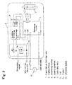
Fig. 2 ] showsEmbodiment 1 of the present invention in the form of a block diagram showing the constitution of the lighting fixture for the electrodeless discharge lamp. - [
Fig. 3 ] showsEmbodiment 1 of the present invention, wherein the contents of the dimmer control are shown. - [
Fig. 4 ] is a schematicdiagram showing Embodiment 1 of the present invention, wherein the relationship between the relative brightness value of the electrodeless discharge lamp and the dimmer voltage at a temperature of -10° C around the instrument. - [
Fig. 5 ] is a schematic diagram ofEmbodiment 1 of the present invention, wherein the relationship between the relative value of the brightness when the dimmer voltage of the electrodeless discharge lamp is used as a parameter and the temperature around the instrument. - [
Fig. 6 ] is a perspective view of the lighting fixture using a conventional electrodeless discharge lamp. - [
Fig. 7 ] is an enlarged view of the essential portion of the conventional electrodeless discharge lamp. - 1: Electrodeless discharge lamp, 2: Lighting fixture, 3: Dimming inverter, 4: Control substrate, 5: Control relay, 5a: Coil, 5b: Contact, 8: Exhaust pipe, 9: Amalgam, 10: Cover, 11: AC power supply;
-
Figs. 1 to 5 show Embodiment 1 of the present invention, of whichFig. 1 shows a lighting fixture for the electrodeless discharge lamp in which the electrodeless discharge lamp, etc. are accommodated,Fig. 2 is a block diagram showing the constitution of the lighting fixture for illuminating the electrodeless discharge,Fig. 3 is a diagram showing the contents of the dimmering control,Fig. 4 is a diagram showing the relationship between the relative brightness value of the electrodeless discharge lamp and the dimmering voltage when the temperature around the apparatus is -10°C, andFig. 5 is a diagram showing the relationship between the relative brightness value and the temperature around the apparatus when the dimmering voltage of the electrodeless discharge lamp is used as a parameter. - As shown in
Fig. 1 , adimmering inverter 3, a controllingrelay 5, etc. are accommodated as well as theelectrodeless discharge lamp 1 in thelighting fixture 1. The range of output of theelectrodeless discharge lamp 1 actually used at present is 100 to 150 W(Watts). - Relating to
Fig. 2 , the internal constitution of thelighting fixture 2 will be descried in detail. Thelighting fixture 2 is connected to the external AC power supply 11 (of, e.g., 200 V, 50/60 Hz), and thus, from theAC power supply 11, power is fed to thedimmering inverter 3 in thelighting fixture 2. The output from thisdimmering inverter 3 is fed to theelectrodeless discharge lamp 1. - The feature of this embodiment of the present invention lies in that the dimmering signal from outside the
lighting fixture 2 is applied to thedimmering inverter 3, whereby dimmering control is performed. - The dimmering signal (for example, 200V, 50/60Hz) is first applied to a
control relay 5. As shown inFig. 3 , in case the dimmering signal is ON, thecoil 5a is energized, and thecontact 5b is shorted, so tat the dimmering signal is applied to thecontrol substrate 4; and thecontrol substrate 4 converts the AC to DC and then applies the DC dimmering signal to the dimmeringinverter 3. Thus, upon receipt of the dimmering signal, thedimmering inverter 3 is brought into a 50% operation mode (which means, the output is dropped to 50% as compared with the usual case). - On the other hand, in the dimmering signal is off, the
contact 5b becomes open, and thus, thedimmer inverter 3 is brought into a 100%-operation mode. - To the
dimmering inverter 3, acontrol substrate 4 for converting AC to DC is added since the dimmering control is DC control. - As shown in
Fig. 4 , if the dimmering voltage (the output voltage of the control substrate 4) applied to thedimmering inverter 3 is made higher than 4V when the ambient temperature of he lightingfixture 2 is -10° C, then an approximately 60% of brightness is obtained. - As shown in
Fig. 5 , when the dimmering voltage is 3V, the amalgam chip temperature of thelighting fixture 2 falls (to -10° C), then the brightness of theelectrodeless discharge lamp 1 extremely falls. If the dimmering voltage is 4.5V, then a brightness of about 60% is obtained. Accordingly, from the practical viewpoint, the dimmer voltage need be made higher than 4V.
Claims (1)
- lighting fixture for an electrodeless discharge lamp comprises an electrodeless discharge lamp, a dimmering inverter connected to an AC power supply and applies a high-frequency voltage to said electrodeless discharge lamp,a controlling relay which turns on/off upon receipt of anAC dimmering signal, and a control substrate which converts said AC dimmering signalfrom said controlling relay into DC and applies a DC dimmering signal to said dimmering inverter, wherein, in case said controlling relay is ON, said controlsubstrate outputs said DC dimmering signal higher than 4 volts,and said dimmering inverter assumes an operation mode of about 50%.
Applications Claiming Priority (2)
| Application Number | Priority Date | Filing Date | Title |
|---|---|---|---|
| JP2005205120A JP2007026788A (en) | 2005-07-14 | 2005-07-14 | Electrodeless discharge lamp lighting system |
| PCT/JP2006/312885 WO2007007554A1 (en) | 2005-07-14 | 2006-06-28 | Electrodeless discharge lamp illuminator |
Publications (1)
| Publication Number | Publication Date |
|---|---|
| EP1903838A1 true EP1903838A1 (en) | 2008-03-26 |
Family
ID=37636950
Family Applications (1)
| Application Number | Title | Priority Date | Filing Date |
|---|---|---|---|
| EP06767502A Withdrawn EP1903838A1 (en) | 2005-07-14 | 2006-06-28 | Electrodeless discharge lamp illuminator |
Country Status (7)
| Country | Link |
|---|---|
| US (1) | US20090121646A1 (en) |
| EP (1) | EP1903838A1 (en) |
| JP (1) | JP2007026788A (en) |
| CN (1) | CN101218858A (en) |
| AU (1) | AU2006267682A1 (en) |
| CA (1) | CA2614686A1 (en) |
| WO (1) | WO2007007554A1 (en) |
Family Cites Families (12)
| Publication number | Priority date | Publication date | Assignee | Title |
|---|---|---|---|---|
| US4628230A (en) * | 1985-08-05 | 1986-12-09 | Mole-Richardson Company | Regulated light dimmer control |
| JPS63245899A (en) * | 1987-03-31 | 1988-10-12 | 東芝ライテック株式会社 | Dimmer in discharge lamp lighter |
| MX9207339A (en) * | 1991-12-17 | 1993-07-01 | Intelliswitch Inc | LIGHTING REGULATOR APPARATUS FOR GAS DISCHARGE LAMPS. |
| JPH0714694A (en) * | 1993-06-16 | 1995-01-17 | Hitachi Lighting Ltd | Discharge lamp dimmer |
| DE4406083A1 (en) * | 1994-02-24 | 1995-08-31 | Patent Treuhand Ges Fuer Elektrische Gluehlampen Mbh | Circuit arrangement for operating at least one low-pressure discharge lamp |
| JPH10148462A (en) * | 1996-11-19 | 1998-06-02 | Sanyo Electric Co Ltd | Low temperature showcase ballast and control method thereof |
| US6218787B1 (en) * | 1998-04-20 | 2001-04-17 | Jrs Technology Inc. | Remote dimming control system for a fluorescent ballast utilizing existing building wiring |
| JP3530060B2 (en) * | 1999-03-15 | 2004-05-24 | 星和電機株式会社 | Discharge lamp lighting device |
| JP2001135491A (en) * | 1999-11-04 | 2001-05-18 | Nec Lighting Ltd | Fluorescent lamp lighting device |
| JP4438249B2 (en) * | 2001-04-24 | 2010-03-24 | パナソニック電工株式会社 | Electrodeless discharge lamp lighting device |
| US6791279B1 (en) * | 2003-03-19 | 2004-09-14 | Lutron Electronics Co., Inc. | Single-switch electronic dimming ballast |
| JP2005100845A (en) * | 2003-09-25 | 2005-04-14 | Matsushita Electric Works Ltd | Lighting device using an electrodeless discharge lamp |
-
2005
- 2005-07-14 JP JP2005205120A patent/JP2007026788A/en active Pending
-
2006
- 2006-06-28 CN CNA2006800252769A patent/CN101218858A/en active Pending
- 2006-06-28 US US11/988,705 patent/US20090121646A1/en not_active Abandoned
- 2006-06-28 AU AU2006267682A patent/AU2006267682A1/en not_active Abandoned
- 2006-06-28 EP EP06767502A patent/EP1903838A1/en not_active Withdrawn
- 2006-06-28 CA CA002614686A patent/CA2614686A1/en not_active Abandoned
- 2006-06-28 WO PCT/JP2006/312885 patent/WO2007007554A1/en not_active Ceased
Non-Patent Citations (1)
| Title |
|---|
| See references of WO2007007554A1 * |
Also Published As
| Publication number | Publication date |
|---|---|
| CA2614686A1 (en) | 2007-01-18 |
| AU2006267682A1 (en) | 2007-01-18 |
| JP2007026788A (en) | 2007-02-01 |
| WO2007007554A1 (en) | 2007-01-18 |
| US20090121646A1 (en) | 2009-05-14 |
| CN101218858A (en) | 2008-07-09 |
Similar Documents
| Publication | Publication Date | Title |
|---|---|---|
| US6828740B2 (en) | Electrodeless discharge lamp operating apparatus, electrodeless compact self-ballasted fluorescent lamp and discharge lamp operating apparatus | |
| CA2795170C (en) | Method of striking a lamp in an electronic dimming ballast circuit | |
| WO2002077740A8 (en) | Electronic ballast for cold cathode fluorescent lamp with dimming | |
| SG158163A1 (en) | Method for programming an operating device for lighting means | |
| JP2010140827A (en) | Lighting device and illumination fixture using the same | |
| CN101167411A (en) | Brightness control of fluorescent lamps | |
| JP4631817B2 (en) | Discharge lamp lighting device and lighting fixture | |
| CN102137529B (en) | Lighting system, LED lighting device and control method thereof | |
| US20090121646A1 (en) | Electrodeless Discharge Lamp Illuminator | |
| ATE389310T1 (en) | METHOD AND CIRCUIT ARRANGEMENT FOR OPERATING A DISCHARGE LAMP | |
| EP1395096A3 (en) | Method to control fluorescent lamps | |
| EP1732367A3 (en) | Ballast circuit for an HID lamp which includes an external starting electrode | |
| EP1976341A1 (en) | Lighting module power-saving control method | |
| JP2003234198A (en) | Lighting device and lighting equipment using this lighting device | |
| US20080174248A1 (en) | Lighting module power-saving control method | |
| TW200949145A (en) | Light-emitting apparatus and dimming method | |
| JP2005183107A (en) | Two-lamp series discharge lamp lighting device and lighting device | |
| JP3177066U (en) | LED lighting power saving control module | |
| KR101740403B1 (en) | Lighting device of electrodeless ball lamp | |
| JP2006040855A (en) | Discharge lamp lighting device, lighting apparatus, and lighting system | |
| KR100814293B1 (en) | AC and DC combined dimmer | |
| RU93193U1 (en) | LIGHTING DEVICE | |
| JP2006310239A (en) | Discharge lamp lighting apparatus for light control | |
| JP2008077866A (en) | Fluorescent lamp lighting device and lighting apparatus | |
| JP2005040260A (en) | Endoscope light source device |
Legal Events
| Date | Code | Title | Description |
|---|---|---|---|
| PUAI | Public reference made under article 153(3) epc to a published international application that has entered the european phase |
Free format text: ORIGINAL CODE: 0009012 |
|
| 17P | Request for examination filed |
Effective date: 20071130 |
|
| AK | Designated contracting states |
Kind code of ref document: A1 Designated state(s): DE FR GB IT |
|
| DAX | Request for extension of the european patent (deleted) | ||
| DAX | Request for extension of the european patent (deleted) | ||
| RBV | Designated contracting states (corrected) |
Designated state(s): DE FR GB IT |
|
| STAA | Information on the status of an ep patent application or granted ep patent |
Free format text: STATUS: THE APPLICATION IS DEEMED TO BE WITHDRAWN |
|
| 18D | Application deemed to be withdrawn |
Effective date: 20090701 |