EP1903526A1 - Alarm management system - Google Patents
Alarm management system Download PDFInfo
- Publication number
- EP1903526A1 EP1903526A1 EP06254883A EP06254883A EP1903526A1 EP 1903526 A1 EP1903526 A1 EP 1903526A1 EP 06254883 A EP06254883 A EP 06254883A EP 06254883 A EP06254883 A EP 06254883A EP 1903526 A1 EP1903526 A1 EP 1903526A1
- Authority
- EP
- European Patent Office
- Prior art keywords
- alarm
- service
- affecting
- flag
- signal
- Prior art date
- Legal status (The legal status is an assumption and is not a legal conclusion. Google has not performed a legal analysis and makes no representation as to the accuracy of the status listed.)
- Withdrawn
Links
Images


Classifications
-
- G—PHYSICS
- G08—SIGNALLING
- G08B—SIGNALLING SYSTEMS, e.g. PERSONAL CALLING SYSTEMS; ORDER TELEGRAPHS; ALARM SYSTEMS
- G08B25/00—Alarm systems in which the location of the alarm condition is signalled to a central station, e.g. fire or police telegraphic systems
Definitions
- This invention relates to the management of alarm signals in a monitoring system.
- Such systems are configured to receive signals from the devices being monitored in the event of a condition exceeding a predetermined value, or some other condition indicative of a malfunction or other condition requiring attention or recording.
- the significance of a fault, overload, or other condition on the system as a whole can depend on a number of factors, many of which are external to the device reporting the condition.
- one device may be used for test purposes, whilst in another part of the system a similar device may be used in "mission critical” or “safety critical” applications.
- the availability of backup resources is not fixed because any backup facility is, necessarily, also subject to similar faults, overloads, and other conditions.
- an alarm management system in which a plurality of devices are capable of transmitting alarm signals to a monitoring centre, the system having the capability of generating first and second alarm signal types, the first type indicative of a service-affecting event and the second indicative of a non-service affecting event, and wherein the monitoring centre is configured to distinguish the two types of signal, to record both types of signal.
- the first type of signal is forwarded to an alerting system, whilst the second type is merely recorded.
- the first and second alarm signal types may be distinguished by the presence or absence of a flag. This flag may be applied autonomously by the device generating the alarm signal. However, in a preferred arrangement a separate function, having overview of the various devices making up the complete system, and their inter-relationships, may determine whether an alarm condition of any particular device is service-affecting. This may take into account dynamic properties, such as the availability or current loading of other devices.
- the alarm signals also include an indication of their severity.
- the monitoring centre may be arranged such that a significance value is applied to the alarm signal, which is a function of both the severity and the presence or absence of a service-affecting flag.
- the presence of the service-affecting flag raises the significance value of any alarm to a value higher than that of any alarm not carrying the flag, whatever their respective severity values.
- three devices 2, 3, 4 form part of a network 1.
- Each device 2, 3, 4 is capable of generating alarm signals 21, 31, 41 having varying severity levels. These different levels indicate, for example, whether the device is approaching or exceeding an overload condition, or a partial or total failure of the device.
- the alarms 21, 31, 41, with their severity levels, are received by an alarm "trap" 5 and forwarded to a monitoring system 6, 7, 8.
- the user of the monitoring system can then use the different severity levels to prioritise remedial work, such as when to dedicate further resources to relieve an overload or replace a failed component.
- each individual component 2, 3, 4 can only report on the significance of the event it is reporting relative to other possible events taking place at the same component.
- a minor defect in a safety-critical component, or one which supports a function of high commercial importance, or a function on which many other functions depend may be much more significant than a similar defect, or even a more major one, in a little-used subsystem, or in an experimental test-rig.
- the availability, or absence, of backup systems for the failed component will determine how significant the failure is to the overall system.
- the invention provides an additional "significance" flag, which is applied to alarms received by the trap 5.
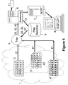
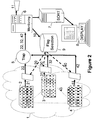
- This significance flag 20, 30, 40 may be applied either by a component 9 of the monitoring system as shown in Figure 1, or as an additional function 29, 39, 49 of the devices 2, 3, 4 generating the alarm, as shown in Figure 2. In either case, the flag to be applied is determined from the operational importance of the device generating the alarm.
- An additional monitoring function 9 may generate this information 20, 30, 40 from network information 10 held in the monitoring system 6.
- the information 20, 30, 40 may be used by the monitoring system 5 to modify the alarm data 21, 31, 41 to generate modified alarm data 22, 32,42 as shown in Figure 1.
- the information 20, 30, 40 may be downloaded to the individual components 29, 39, 49 as shown in Figure 2, so that they can generate the appropriate modified alarms 22, 32, 42 themselves.
- the alarm signals are modified by setting a "flag" 20, 30, 40 if the respective device 2, 3, 4 is service-critical.
- the operation of the monitoring system 6 and display system 7 is illustrated in Figure 3, with a typical display represented in Figure 4.
- the monitoring system 6 receives the modified alarm signals 22, 32, 42 (step 60). It reads the severity value 21, 22, 32 (step 61) and also determines whether the significance flag 20, 30, 40 is set (step 62). If the flag is set, an alert 64 is generated on an alarm system 11 to call attention to the event.
- a significance value 23, 33, 43 is generated (step 63) the data received by the monitoring system. This value is determined by the severity value 21, 31, 41 of the alarm and by whether the flag 20, 30, 40 has been set. In this embodiment the significance value is set at the sum of the severity value and a second value F which is set equal to zero if the flag is not set, and to a value greater than the maximum severity value if the flag is set. (In the example shown in Figure 4, the severity values 82 for the events 81 are in a range from 1 to 5, and the flag value F is set to zero or 10, so that the significance values 85 for critical events fall in the range 11 to 15).
- Alerts can then be passed to a processor 7 in which they are sorted in order of their significance values 85 (step 70) for presentation on a display device 8.
- the display 8 is updated on receipt of each alert (step 80), the location 81, severity 82, time 83 and, if appropriate, the critical nature 84 of each event being recorded.
- all the alarms 800, 801, 802 for which the flags have been set are grouped together and take priority over any alarms 810, 811 7-8819 for which the flag is not set. This is the case even though some of the non-critical alarms 810, 811, 812, have severity values 82 higher than any of those for the critical alarms 800, 801, 802. This allows an operator to readily identify the events of critical significance, to which he has been alerted by the alarm system 11, as such events will be displayed first, followed by those of a 'normal' severity.
- the significance flag may be set by external correlation processes when appropriate. For example if a system 2 determines that an event has occurred a predetermined number of times within a time period, this may be reported to, or detected by, the monitoring system 6 which sets the appropriate flag 20 such that the significance of events occurring to that device 2 are enhanced. Similar correlation may be used between reports emanating from different devices 3, 4. This may be appropriate if, for example, the failure of both devices 3, 4 is indicative of a more widespread problem, or of a link 34 between them. Again, service may be unaffected by the failure of either of a pair of duplicate devices, but failure of both may be a service-affecting event.
Landscapes
- Business, Economics & Management (AREA)
- Emergency Management (AREA)
- Physics & Mathematics (AREA)
- General Physics & Mathematics (AREA)
- Debugging And Monitoring (AREA)
Abstract
Device 2, 3, 4 are capable of generating alarm signals 21, 31, 41 having varying severity levels indicating, for example, whether the device is approaching or exceeding an overload condition, or a partial or total failure of the device. The alarms 21, 31, 41, with their severity levels, are received by an alarm "trap" 5 and forwarded to a monitoring system 6, 7, 8. The invention provides an additional "significance" flag, relating to the operational importance of the device generating the alarm, which is applied to alarms received by the trap 5. The significance and severity flags are used to sort the alarms in order to identify the most significant alarms. An additional monitoring function 9 may generate this information 20, 30, 40 from network information 10 held in the monitoring system 6. The information 20, 30, 40 is used by the monitoring system 5 to modify the alarm data 21, 31, 41 to generate modified alarm data 22, 32,42.
Description
- This invention relates to the management of alarm signals in a monitoring system. Such systems are configured to receive signals from the devices being monitored in the event of a condition exceeding a predetermined value, or some other condition indicative of a malfunction or other condition requiring attention or recording.
- In a complex system the significance of a fault, overload, or other condition on the system as a whole can depend on a number of factors, many of which are external to the device reporting the condition. For example, one device may be used for test purposes, whilst in another part of the system a similar device may be used in "mission critical" or "safety critical" applications. In the latter case, there may, or may not, be backup resources available in the event of such failure or overload. The availability of backup resources is not fixed because any backup facility is, necessarily, also subject to similar faults, overloads, and other conditions.
- There is therefore a need to indicate the critical events which actually affect service, such that allocation of resource to meet such conditions can be prioritised accordingly.
- According to the invention, there is provided an alarm management system in which a plurality of devices are capable of transmitting alarm signals to a monitoring centre, the system having the capability of generating first and second alarm signal types, the first type indicative of a service-affecting event and the second indicative of a non-service affecting event, and wherein the monitoring centre is configured to distinguish the two types of signal, to record both types of signal. In one embodiment, the first type of signal is forwarded to an alerting system, whilst the second type is merely recorded.
- The first and second alarm signal types may be distinguished by the presence or absence of a flag. This flag may be applied autonomously by the device generating the alarm signal. However, in a preferred arrangement a separate function, having overview of the various devices making up the complete system, and their inter-relationships, may determine whether an alarm condition of any particular device is service-affecting. This may take into account dynamic properties, such as the availability or current loading of other devices.
- In a preferred arrangement, the alarm signals also include an indication of their severity. The monitoring centre may be arranged such that a significance value is applied to the alarm signal, which is a function of both the severity and the presence or absence of a service-affecting flag. In the embodiment to be described, the presence of the service-affecting flag raises the significance value of any alarm to a value higher than that of any alarm not carrying the flag, whatever their respective severity values.
- An embodiment of the invention will now be described, by way of example, with reference to the Figures, in which
- Figure 1 is a schematic depiction of the various elements that co-operate to form a first embodiment of the invention, and the message flows between them
- Figure 2 is a schematic depiction of the various elements that co-operate to form a second embodiment of the invention, and the message flows between them
- Figure 3 is a depiction of the process performed by the invention
- Figure 4 depicts in tabular form a series of alarms, and a typical display layout for these alarms.
- In these embodiments, three
devices network 1. Eachdevice alarm signals alarms monitoring system - However, each
individual component - To overcome this problem, the invention provides an additional "significance" flag, which is applied to alarms received by the
trap 5. This significance flag 20, 30, 40 may be applied either by acomponent 9 of the monitoring system as shown in Figure 1, or as an additional function 29, 39, 49 of thedevices additional monitoring function 9 may generate thisinformation network information 10 held in themonitoring system 6. Theinformation monitoring system 5 to modify thealarm data alarm data information alarms respective device - The operation of the
monitoring system 6 anddisplay system 7 is illustrated in Figure 3, with a typical display represented in Figure 4. Themonitoring system 6 receives the modifiedalarm signals severity value alert 64 is generated on analarm system 11 to call attention to the event. - A
significance value 23, 33, 43 is generated (step 63) the data received by the monitoring system. This value is determined by theseverity value flag severity values 82 for theevents 81 are in a range from 1 to 5, and the flag value F is set to zero or 10, so that the significance values 85 for critical events fall in therange 11 to 15). - Alerts can then be passed to a
processor 7 in which they are sorted in order of their significance values 85 (step 70) for presentation on adisplay device 8. In this embodiment thedisplay 8 is updated on receipt of each alert (step 80), thelocation 81,severity 82,time 83 and, if appropriate, thecritical nature 84 of each event being recorded. As shown in Figure 4, all thealarms alarms non-critical alarms severity values 82 higher than any of those for thecritical alarms alarm system 11, as such events will be displayed first, followed by those of a 'normal' severity. - The significance flag may be set by external correlation processes when appropriate. For example if a
system 2 determines that an event has occurred a predetermined number of times within a time period, this may be reported to, or detected by, themonitoring system 6 which sets theappropriate flag 20 such that the significance of events occurring to thatdevice 2 are enhanced. Similar correlation may be used between reports emanating fromdifferent devices devices
Claims (18)
- Alarm management system in which a plurality of devices are capable of transmitting alarm signals to a monitoring centre, the system having the capability of generating first and second alarm signal types, the first type indicative of a service-affecting event and the second indicative of a non-service affecting event, and wherein the monitoring centre is configured to distinguish the two types of signal, and to record both types of signal, and to generate different responses to the two types of signal.
- An alarm management system according to claim 1, having means to forward only the first type of signal to an alerting system.
- An alarm management system according to claim 1 or claim 2, comprising means in the device generating the alarm signal for applying a flag to the first type of signal, and means in the monitoring centre for identifying the presence or absence of the flag.
- An alarm management system according to claim 3 wherein the device generating the alarm signal determines whether to apply the flag autonomously.
- An alarm management system according to claim 3, wherein the monitoring system determines, from the inter-relationships of the monitored devices, whether an alarm condition of any particular device is service-affecting, and generates instructions for the monitored devices to determine the conditions under which the flag should be applied.
- An alarm management system according to claim 5, having means for determining dynamic properties of devices related to each other, and means for generating instructions for each of the related devices in accordance with the said dynamic properties.
- An alarm management system according to claim 6, in which the alarm signals also include an indication of their severity.
- An alarm management system according to any preceding claim in which a significance value is applied to each alarm signal, the significance value being a function of both the severity and of whether the condition is service-affecting.
- An alarm management system according to claim 8, in which the significance value of any service-affecting condition is raised to a value higher than that of any non-service affecting condition, whatever their respective severity values.
- A method of handling alarm signals generated by a plurality of devices, wherein first and second alarm signal types are generated, the first type indicative of a service-affecting event and the second indicative of a non-service affecting event, a monitoring centre records the signals and generates a first type of response to signals of the first type, and a different response to signals of the second type.
- A method according to claim 10, wherein only the first type of signal is forwarded to an alerting system.
- A method according to claim 10 or claim 11, wherein a flag is applied to signals of the first type, and the monitoring centre identifies the presence or absence of the flag.
- A method according to claim 12, wherein the device generating the alarm signal determines whether to apply the flag autonomously.
- A method according to claim 12, wherein the monitoring system determines, from the inter-relationships of the monitored devices, whether an alarm condition of any particular device is service-affecting, and generates instructions for the monitored devices to determine the conditions under which the flag should be applied.
- A method according to claim 14, wherein the monitoring system determines dynamic properties of devices related to each other and generates instructions for each of the related devices in accordance with the said dynamic properties.
- A method according to claim 15, in which the alarm signals also include an indication of their severity.
- A method according to claim 10, 11, 12, 13 14, 15 or 16 in which a significance value is applied to each alarm signal, the significance value being a function of both the severity and of whether the condition is service-affecting.
- A method according to claim 17, in which the significance value of any service-affecting condition is raised to a value higher than that of any non-service affecting condition, whatever their respective severity values.
Priority Applications (1)
| Application Number | Priority Date | Filing Date | Title |
|---|---|---|---|
| EP06254883A EP1903526A1 (en) | 2006-09-20 | 2006-09-20 | Alarm management system |
Applications Claiming Priority (1)
| Application Number | Priority Date | Filing Date | Title |
|---|---|---|---|
| EP06254883A EP1903526A1 (en) | 2006-09-20 | 2006-09-20 | Alarm management system |
Publications (1)
| Publication Number | Publication Date |
|---|---|
| EP1903526A1 true EP1903526A1 (en) | 2008-03-26 |
Family
ID=37836640
Family Applications (1)
| Application Number | Title | Priority Date | Filing Date |
|---|---|---|---|
| EP06254883A Withdrawn EP1903526A1 (en) | 2006-09-20 | 2006-09-20 | Alarm management system |
Country Status (1)
| Country | Link |
|---|---|
| EP (1) | EP1903526A1 (en) |
Cited By (1)
| Publication number | Priority date | Publication date | Assignee | Title |
|---|---|---|---|---|
| CN115104110A (en) * | 2020-02-10 | 2022-09-23 | 西班牙毕尔巴鄂比斯开银行 | Method and system for monitoring alarms |
Citations (3)
| Publication number | Priority date | Publication date | Assignee | Title |
|---|---|---|---|---|
| JPH01166199A (en) * | 1987-12-22 | 1989-06-30 | Nippon Atom Ind Group Co Ltd | Alarm device |
| JPH09214510A (en) * | 1996-02-05 | 1997-08-15 | Nec Corp | Method for collecting alarm of network |
| US20020055790A1 (en) * | 2000-11-07 | 2002-05-09 | Havekost Robert B. | Enhanced device alarms in a process control system |
-
2006
- 2006-09-20 EP EP06254883A patent/EP1903526A1/en not_active Withdrawn
Patent Citations (3)
| Publication number | Priority date | Publication date | Assignee | Title |
|---|---|---|---|---|
| JPH01166199A (en) * | 1987-12-22 | 1989-06-30 | Nippon Atom Ind Group Co Ltd | Alarm device |
| JPH09214510A (en) * | 1996-02-05 | 1997-08-15 | Nec Corp | Method for collecting alarm of network |
| US20020055790A1 (en) * | 2000-11-07 | 2002-05-09 | Havekost Robert B. | Enhanced device alarms in a process control system |
Cited By (1)
| Publication number | Priority date | Publication date | Assignee | Title |
|---|---|---|---|---|
| CN115104110A (en) * | 2020-02-10 | 2022-09-23 | 西班牙毕尔巴鄂比斯开银行 | Method and system for monitoring alarms |
Similar Documents
| Publication | Publication Date | Title |
|---|---|---|
| CN103544093B (en) | Monitoring alarm control method and system thereof | |
| US11157343B2 (en) | Systems and methods for real time computer fault evaluation | |
| JPH08506946A (en) | Event correlation in communication networks | |
| CN109639504B (en) | Alarm information processing method and device based on cloud platform | |
| CN110740061A (en) | Fault early warning method and device and computer storage medium | |
| CN113808725A (en) | Equipment early warning system and method | |
| US8943102B2 (en) | Alarm management system | |
| CN107453906A (en) | A kind of method to set up and device of storage management system monitoring alarm | |
| JP2012080181A (en) | Method and program for fault information management | |
| CN106878096B (en) | VNF state detection notification method, device and system | |
| JP2010015246A (en) | Failure information analysis management system | |
| CN108398926A (en) | Monitoring arrangement, lathe and monitoring system | |
| US8275865B2 (en) | Methods, systems and computer program products for selecting among alert conditions for resource management systems | |
| CN112181780A (en) | Detection and alarm method, device and equipment for containerized platform core component | |
| JP5126137B2 (en) | Network management system and program | |
| JP2003271557A (en) | Failure information analysis method | |
| CN118312381A (en) | A method and system for service monitoring and alarming | |
| US11862007B2 (en) | Method for automatically analyzing and filtering out redundant alarms in the fault management system of radio transceiver stations | |
| JP7034989B2 (en) | Alarm aggregation sorting device and alarm aggregation sorting method | |
| KR20140120200A (en) | Early warning system and method for database error | |
| JP2010152469A (en) | Log collection process monitoring system | |
| JP2003345629A (en) | System monitor device, system monitoring method used for the same, and program therefor | |
| CN113505047A (en) | System for centralized management monitoring of each distribution center website database | |
| KR102927848B1 (en) | Integrated IT Operations Management System and Method for Information System Status Management | |
| JPH06324916A (en) | Fault information logging system |
Legal Events
| Date | Code | Title | Description |
|---|---|---|---|
| PUAI | Public reference made under article 153(3) epc to a published international application that has entered the european phase |
Free format text: ORIGINAL CODE: 0009012 |
|
| AK | Designated contracting states |
Kind code of ref document: A1 Designated state(s): AT BE BG CH CY CZ DE DK EE ES FI FR GB GR HU IE IS IT LI LT LU LV MC NL PL PT RO SE SI SK TR |
|
| AX | Request for extension of the european patent |
Extension state: AL BA HR MK YU |
|
| AKX | Designation fees paid | ||
| REG | Reference to a national code |
Ref country code: DE Ref legal event code: 8566 |
|
| STAA | Information on the status of an ep patent application or granted ep patent |
Free format text: STATUS: THE APPLICATION IS DEEMED TO BE WITHDRAWN |
|
| 18D | Application deemed to be withdrawn |
Effective date: 20080927 |