EP1903416A2 - Rotary metering valve arrangement - Google Patents
Rotary metering valve arrangement Download PDFInfo
- Publication number
- EP1903416A2 EP1903416A2 EP07253569A EP07253569A EP1903416A2 EP 1903416 A2 EP1903416 A2 EP 1903416A2 EP 07253569 A EP07253569 A EP 07253569A EP 07253569 A EP07253569 A EP 07253569A EP 1903416 A2 EP1903416 A2 EP 1903416A2
- Authority
- EP
- European Patent Office
- Prior art keywords
- valve
- latching
- fuel
- valve element
- ports
- Prior art date
- Legal status (The legal status is an assumption and is not a legal conclusion. Google has not performed a legal analysis and makes no representation as to the accuracy of the status listed.)
- Granted
Links
- 239000000446 fuel Substances 0.000 claims abstract description 63
- 239000012530 fluid Substances 0.000 claims description 4
- 230000015572 biosynthetic process Effects 0.000 claims 1
- 230000001419 dependent effect Effects 0.000 description 2
- 229920006364 Rulon (plastic) Polymers 0.000 description 1
- 238000005299 abrasion Methods 0.000 description 1
- 230000004075 alteration Effects 0.000 description 1
- 230000008901 benefit Effects 0.000 description 1
- 230000008859 change Effects 0.000 description 1
- 230000001627 detrimental effect Effects 0.000 description 1
- 238000010586 diagram Methods 0.000 description 1
- 230000000694 effects Effects 0.000 description 1
- 230000003116 impacting effect Effects 0.000 description 1
- 239000000463 material Substances 0.000 description 1
- 238000012986 modification Methods 0.000 description 1
- 230000004048 modification Effects 0.000 description 1
- 238000012544 monitoring process Methods 0.000 description 1
- 230000009467 reduction Effects 0.000 description 1
Images

Classifications
-
- F—MECHANICAL ENGINEERING; LIGHTING; HEATING; WEAPONS; BLASTING
- F02—COMBUSTION ENGINES; HOT-GAS OR COMBUSTION-PRODUCT ENGINE PLANTS
- F02C—GAS-TURBINE PLANTS; AIR INTAKES FOR JET-PROPULSION PLANTS; CONTROLLING FUEL SUPPLY IN AIR-BREATHING JET-PROPULSION PLANTS
- F02C9/00—Controlling gas-turbine plants; Controlling fuel supply in air- breathing jet-propulsion plants
- F02C9/26—Control of fuel supply
- F02C9/263—Control of fuel supply by means of fuel metering valves
-
- F—MECHANICAL ENGINEERING; LIGHTING; HEATING; WEAPONS; BLASTING
- F02—COMBUSTION ENGINES; HOT-GAS OR COMBUSTION-PRODUCT ENGINE PLANTS
- F02C—GAS-TURBINE PLANTS; AIR INTAKES FOR JET-PROPULSION PLANTS; CONTROLLING FUEL SUPPLY IN AIR-BREATHING JET-PROPULSION PLANTS
- F02C7/00—Features, components parts, details or accessories, not provided for in, or of interest apart form groups F02C1/00 - F02C6/00; Air intakes for jet-propulsion plants
- F02C7/22—Fuel supply systems
- F02C7/232—Fuel valves; Draining valves or systems
-
- F—MECHANICAL ENGINEERING; LIGHTING; HEATING; WEAPONS; BLASTING
- F16—ENGINEERING ELEMENTS AND UNITS; GENERAL MEASURES FOR PRODUCING AND MAINTAINING EFFECTIVE FUNCTIONING OF MACHINES OR INSTALLATIONS; THERMAL INSULATION IN GENERAL
- F16K—VALVES; TAPS; COCKS; ACTUATING-FLOATS; DEVICES FOR VENTING OR AERATING
- F16K11/00—Multiple-way valves, e.g. mixing valves; Pipe fittings incorporating such valves
- F16K11/02—Multiple-way valves, e.g. mixing valves; Pipe fittings incorporating such valves with all movable sealing faces moving as one unit
- F16K11/06—Multiple-way valves, e.g. mixing valves; Pipe fittings incorporating such valves with all movable sealing faces moving as one unit comprising only sliding valves, i.e. sliding closure elements
- F16K11/072—Multiple-way valves, e.g. mixing valves; Pipe fittings incorporating such valves with all movable sealing faces moving as one unit comprising only sliding valves, i.e. sliding closure elements with pivoted closure members
- F16K11/074—Multiple-way valves, e.g. mixing valves; Pipe fittings incorporating such valves with all movable sealing faces moving as one unit comprising only sliding valves, i.e. sliding closure elements with pivoted closure members with flat sealing faces
-
- F—MECHANICAL ENGINEERING; LIGHTING; HEATING; WEAPONS; BLASTING
- F05—INDEXING SCHEMES RELATING TO ENGINES OR PUMPS IN VARIOUS SUBCLASSES OF CLASSES F01-F04
- F05D—INDEXING SCHEME FOR ASPECTS RELATING TO NON-POSITIVE-DISPLACEMENT MACHINES OR ENGINES, GAS-TURBINES OR JET-PROPULSION PLANTS
- F05D2250/00—Geometry
- F05D2250/40—Movement of components
- F05D2250/41—Movement of components with one degree of freedom
- F05D2250/411—Movement of components with one degree of freedom in rotation
-
- Y—GENERAL TAGGING OF NEW TECHNOLOGICAL DEVELOPMENTS; GENERAL TAGGING OF CROSS-SECTIONAL TECHNOLOGIES SPANNING OVER SEVERAL SECTIONS OF THE IPC; TECHNICAL SUBJECTS COVERED BY FORMER USPC CROSS-REFERENCE ART COLLECTIONS [XRACs] AND DIGESTS
- Y02—TECHNOLOGIES OR APPLICATIONS FOR MITIGATION OR ADAPTATION AGAINST CLIMATE CHANGE
- Y02T—CLIMATE CHANGE MITIGATION TECHNOLOGIES RELATED TO TRANSPORTATION
- Y02T50/00—Aeronautics or air transport
- Y02T50/60—Efficient propulsion technologies, e.g. for aircraft
Definitions
- This invention relates to a metering valve arrangement for use in controlling the supply of fuel to an engine.
- the invention relates to a rotary metering valve arrangement.
- a rotary metering valve is disclosed in US 3915188 which comprises a valve plate in which a metering orifice is provided.
- a valve element is angularly movable under the control of, for example, a suitable motor between a position in which the metering orifice is closed by the valve element and an open position.
- the valve element in order to have a low co-efficient of friction and a good abrasion resistance, is typically manufactured from a bearing material such as Rulon.
- turbo-prop With some designs of fuel system, for example those designed for use with turbo-prop engines, it is desirable that in the event of an electrical power failure to the engine and associated control system the turbo-prop continues to operate at the speed at which it was operating immediately prior to the failure by holding the fuel metering valve against movement and using a back-up hydromechanical governor.
- the use of a rotary metering valve in such applications has the advantage that in the event of a power failure, the metering valve is held against movement, for example by the brake arrangement associated with the motor normally used to move the valve element thereof.
- This arrangement provides a low cost and reliable solution to incorporating a latching capability into a fuel system.
- valve plate and valve element In a rotary metering valve, the hydraulic and frictional forces applied, in use, to the valve plate and valve element thereof are complex and these components have to be carefully designed to avoid the valve element 'sticking' to the valve plate.
- the provision of a hydraulic latching capability using, for example, a porting arrangement provided in the valve plate and/or valve element may increase the risk of such 'sticking' as this will change the balance of the hydraulically applied forces experienced by the valve elements. If there is a risk of such 'sticking' occurring, then it may be necessary to provide a larger motor than may otherwise be necessary to ensure that the valve element can always be driven to its desired position.
- the provision of a larger motor has cost and weight penalties.
- the risk of 'sticking' can be mitigated by reducing the hydraulic and frictional forces applied to the valve element, which can be achieved by reducing the surface area of the valve element.
- a rotary metering valve arrangement comprising a rotary metering valve arranged to control the supply of fuel to a Pressure Raising and Shut-Off Valve (PRSOV), the metering valve comprising a valve plate provided with first and second latching ports and an angularly movable valve element provided with a recess registrable, in use, with the first and second latching ports to control communication therebetween, the PRSOV comprising a valve member slidable within a bore provided with third and fourth latching ports, the valve member being provided with a recess registrable, in use, with the third and fourth latching ports to control communication therebetween, the second and third latching ports communicating with one another.
- PRSOV Pressure Raising and Shut-Off Valve
- such an arrangement can be operated such that, in the event of the PRSOV moving to a shut-off position, on operation of a control valve, for example in the form of a Non-Latching Solenoid controlled Shut-Off Valve (NLSSOV), communication is established between the first and fourth latching ports, via the second and third latching ports.
- NLSSOV Non-Latching Solenoid controlled Shut-Off Valve
- the first port conveniently communicates with a control chamber of a Pressure Drop Spill Valve (PDSV).
- PDSV Pressure Drop Spill Valve
- At least one of the first and second latching ports is conveniently located at a small radial distance from an axis of angular movement of the valve element.
- the other of the first and second latching ports is conveniently defined by a series of openings in fluid communication with one another and positioned at different angular locations, and at different distances from the axis of angular movement of the valve element.
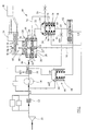
- FIG. 1 there is illustrated, diagrammatically, a fuel system for use in the delivery of fuel to a turbo-prop gas turbine engine.
- the fuel system comprises a low pressure pump 10 arranged to supply fuel from a reservoir through a filter 12 to the inlet side of a high pressure fuel pump 14.
- the fuel pump 14 delivers fuel to a supply line 16 in which is provided a flow washed filter 18.
- a rotary metering valve arrangement 19 includes a rotary metering valve 20 which has an inlet connected to the supply line 16 and an outlet from which fuel is delivered through a delivery line 22 to a Pressure Raising and Shut-Off Valve (PRSOV) 24.
- PRSOV Pressure Raising and Shut-Off Valve
- the rotary metering valve 20 comprises a housing in which is located a valve plate 26 having a metering orifice 28 formed therein.
- a valve element 30 abuts a surface of the valve plate 26 and is angularly movable about an axis 30a by a drive arrangement 32 to vary the degree by which the valve element 30 obscures the metering orifice 28.
- fuel is only able to flow through the metering valve 20 from a chamber 16a thereof communicating with the supply line 16 to a chamber 22a thereof communicating with the delivery line 22 at a low rate. Movement of the valve element 30 under the control of the drive arrangement 32 to increase the area of the metering orifice 28 available for fuel to flow through increases the rate of fuel supply to the PRSOV 24.
- the drive arrangement 32 conveniently comprises a stepper motor 34 and gear arrangement 36 operable to drive a drive shaft 38 connected to the valve element 30.
- a Rotary Variable Differential Transformer (RVDT) 40 monitors the angular position of the shaft 38, and hence the position of the valve element 30, and provides a rotational position signal to a Propulsion Control and Monitoring Unit (PCMU) 42 which is used to control the operation of the stepper motor 34.
- RVDT Rotary Variable Differential Transformer
- PCMU Propulsion Control and Monitoring Unit
- a Pressure Drop Spill Valve (PDSV) 44 is provided and comprises a spring biased valve element 46 movable within a bore. One surface of the valve element 46 is exposed to fuel at high pressure from the supply line 16. An opposing surface of the valve element 46 defines, in part, a control chamber 48 which communicates through a line 50 with the chamber 22a of the metering valve 20 located downstream of the metering orifice 28. It will be appreciated that the position occupied by the valve element 46 is dependent upon the pressure difference between the supply line 16 and the line 50.
- valve element 46 In the event that the pressure difference exceeds a predetermined level, then the valve element 46 will be moved to a position in which a spill port 44a of the PDSV 44 is opened, thereby allowing fuel to be spilt through the PDSV 44 to the low pressure side of the pump 14. It will be appreciated from Figure 1 that the line 50 communicates with chamber 22a through a pull down orifice 52 formed in the valve plate 26.
- the PRSOV 24 comprises a valve element 54 slidable within a bore and movable to control the degree by which an outlet port is obscured.
- the valve element 54 occupies an open position, as illustrated, then fuel from the delivery line 22 is delivered through the PRSOV 24 through an outlet line 56 to the burners of the engine.
- the valve element 54 occupies a position in which the outlet port is closed, the supply of fuel to the engine is terminated.
- the position occupied by the valve element 54 is dependent upon the fluid pressure within a control chamber 58 of the PRSOV 24.
- control chamber 58 In normal operation, when there is fuel flow to the engine, the control chamber 58 communicates through a line 60 and Non-Latching Solenoid Shut-Off Valve (NLSSOV) 62 with the low pressure side of the pump 14.
- the line 60 further communicates through a restrictor 64 with a fuel line connected to the filter 18. It will be appreciated that, in normal operation, the restrictor 64 and valve 62 together form a fluid potentiometer network arrangement, and thus that the control chamber 58 is held at an intermediate pressure.
- the NLSSOV 62 in addition to controlling communication between the control chamber 58 and low pressure, further controls communication between the line 50, and hence the control chamber 48 of the PDSV 44, and the low pressure side of the pump 14.
- the valve 62 In normal operation, when there is fuel flow to the engine, the valve 62 is held in a position in which communication between the line 50 and low pressure side of the pump 14 is broken, the valve 62 forming a restricted flow path between the line 60 and the low pressure side of the pump 14.
- First and second latching ports 66, 68 are provided in the valve plate 26.
- the first latching port 66 communicates with the line 50.
- the second latching port 68 communicates via a line 70 with a third latching port 72 provided in the PRSOV 24.
- a fourth latching port 74 provided in the PRSOV 24 communicates with the low pressure side of the pump 14.
- the valve element 30 of the metering valve is provided with a recess 76 which, depending upon the angular position of the valve element 30, is registrable with the first and second latching ports 66, 68 to permit communication therebetween.
- An annular recess 78 provided in the valve element 54 of the PRSOV 24 is arranged such that when the PRSOV 24 occupies its shut-off position, and fuel flow to the engine is terminated, communication is permitted between third and fourth latching ports 72, 74, such communication being broken when the PRSOV 24 is in an open position (as shown), and there is fuel flow to the engine.
- Figure 1 illustrates the fuel system in a normal operating condition in which there is fuel flow to the engine and the recess 76 registers with the first and second latching ports 66, 68 and in which the PRSOV 24 occupies an open position, thus communication between the third and fourth latching ports 72, 74 is broken.
- the NLSSOV62 occupies its 'fuel-on' operating position in which communication between the line 50 and the low pressure side of the pump 14 is broken, the valve 62 acting as a restricted flow path between the line 60 and the low pressure side of the pump 14.
- the angular position of the valve element 30 is controlled by the drive arrangement 32 to control the degree by which the metering orifice 28 is obscured, thereby controlling the rate at which fuel is delivered to the PRSOV 24 and to the engine burners.
- the PDSV 44 operates during this phase in the operation of the fuel system to maintain a substantially constant pressure drop across the metering valve 20.
- the NLSSOV 62 changes state from a 'fuel-on' to a 'fuel-off position, and breaks communication between the line 60 and the low pressure side of the pump 14. Consequently, the fuel pressure within the control chamber 58 of the PRSOV 24 increases due to the connection of the line 60 to the high pressure delivery line 16 via the restrictor 64 and the filter 18, resulting in the valve element 54 thereof moving to its shut-off position, terminating the supply of fuel to the engine burners.
- valve 62 Simultaneously, communication is established through the valve 62 between the line 50 and the low pressure side of the pump 14 resulting in the fuel pressure within the control chamber 48 of the PDSV 44 being vented to low pressure.
- the valve element 46 thereof moves to a position in which the output of the pump 14 is spilt back to the low pressure side thereof through the PDSV 44.
- the movement of the PRSOV 24 to its shut-off position brings the recess 78 into registration with both the third and fourth latching ports 72, 74 bringing these ports into communication with one another.
- the fourth port 74 is connected to the low pressure side of the pump 14, it will be appreciated that a consequence of the movement of the valve element 54 to its shut-off position is to connect the line 70, second latching port 68, and hence first latching port 66 to the low pressure side of the pump 14.
- the line 50 is thus connected to low pressure both through the latching ports and through the valve 62.
- the NLSSOV 62 can now be allowed to return to its 'fuel-on' operating position as illustrated in Figure 1, with the fuel system hydraulically latched in the shut-down condition.
- the "by-pass" communication path between the fourth latching port 74 and first latching port 66 via the second and third latching ports 68, 72 ensures that the control chamber 48 of the PDSV 44 remains connected to the low pressure side of the pump 14. Consequently, the PDSV 44 will remain open, spilling all of the output of the pump 14 back to the inlet side thereof, thereby ensuring that the pressure drop across the PRSOV 24 is below that required to overcome the PRSOV spring 59 and so holding the PRSOV 24 and the fuel system in a configuration in which fuel is not supplied to the engine burners despite the NLSSOV 62 occupying its 'fuel-on' position. Hence the PRSOV 24 and consequently the fuel system are hydraulically latched in the shut-down condition.
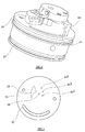
- the recess 76 provided in the underside of the valve element 30 is of generally L-shaped configuration and is arranged to communicate with the first port 66 throughout its range of movement.
- the range of movement of the valve element 30 is limited by a hard stop member 80 forming part of the drive arrangement 32 which is able to ride within an arcuate slot 82 formed in the valve plate 26, movement of the valve 30 being limited by engagement of the member 80 with the ends of the arcuate slot 82. This engagement defines the maximum and minimum flow limits of the rotary metering valve.
- the second port 68 is defined by three separate openings 84 a 84 b 84 c which communicate with one another within the body of the valve plate 26, which are located at different radial positions on the valve plate 26 and which are angularly positioned such that, with the valve element 30 moving in the clockwise direction as illustrated in Figure 4, communication between the recess 76 and a second one of the openings 84b commences before communication between the recess 76 and a first one of the openings 84a is broken. Likewise, communication commences between the recess 76 and the third opening 84c before communication is broken between the recess 76 and the second opening 84b.
- Such an arrangement enables the ports 66, 68 to be located relatively close to the axis 30a, and minimises the surface area of the valve element 30, thus minimising the risk of the motor 34 being unable to move the valve element 30 to the desired position.
- the system pressure will rise to a sufficiently high level to open the PRSOV 24, breaking the communication between the third and fourth latching ports, and that fuel can be supplied through the PRSOV 24 to the engine burners in the usual manner.
- the PRSOV 24 Once the PRSOV 24 has opened, it is possible to move the valve element 30 and open the metering orifice 28 to a higher flow condition. This reestablishes communication between the first and second latching ports 66, 68, but does not result in a shut-down condition since the pressure in the PDSV control chamber 48 is no longer vented to LP, the path being cut-off at the PRSOV where the communication between the third and fourth latching ports is broken.
- first and second latching ports 66, 68 are such that the surface area of the valve element 30 and the corresponding forces acting thereon are minimised and consequently risk of the valve element 30 tending to stick to the valve plate 26 is minimised whilst the rotational movement of the valve element 30 is unaffected. Consequently, the provision of a relatively large drive arrangement and positional feedback arrangement for the rotary metering valve 20 can be avoided, resulting in an optimised solution to the problem of incorporating hydraulic latching capability in a rotary metering valve arrangement with regards to minimising the cost and weight of the system.
- the latching porting arrangement described herein ensures that when the fuel system is in the shut-down condition the latching capability is predominantly unaffected by subsequent operation/condition of the rotary metering valve, in that the rotary metering valve must be returned to its minimum fuel delivery position before the PRSOV can be de-latched and the fuel system re-set.
- the second latching port 68 in this embodiment, includes three outlets located at different radial and angular positions, where space allows other designs may be used to provide the required hydraulic latching capability, whilst not impacting the performance of the fuel system or incurring unacceptable cost and weight penalities.
- Figure 5 illustrates an arrangement similar to that described hereinbefore but in which the first and second latching ports 66, 68 are located at a radial position remote from the axis 30a of angular movement of the valve element 30.
- the recess 76 provided in the valve element 30 is of arcuate form.
- the location of the first and second latching ports 66, 68 in this position may, in some circumstances, be unacceptable as it results in the valve element 30 being relatively large and may increase the risk of the valve element 30 sticking to the valve plate 26, in use. However, there may be applications in which this is acceptable.
Landscapes
- Engineering & Computer Science (AREA)
- General Engineering & Computer Science (AREA)
- Chemical & Material Sciences (AREA)
- Combustion & Propulsion (AREA)
- Mechanical Engineering (AREA)
- Feeding And Controlling Fuel (AREA)
- Multiple-Way Valves (AREA)
Abstract
Description
- This invention relates to a metering valve arrangement for use in controlling the supply of fuel to an engine. In particular, the invention relates to a rotary metering valve arrangement.
- A rotary metering valve is disclosed in
US 3915188 which comprises a valve plate in which a metering orifice is provided. A valve element is angularly movable under the control of, for example, a suitable motor between a position in which the metering orifice is closed by the valve element and an open position. The valve element, in order to have a low co-efficient of friction and a good abrasion resistance, is typically manufactured from a bearing material such as Rulon. - With some designs of fuel system, for example those designed for use with turbo-prop engines, it is desirable that in the event of an electrical power failure to the engine and associated control system the turbo-prop continues to operate at the speed at which it was operating immediately prior to the failure by holding the fuel metering valve against movement and using a back-up hydromechanical governor. The use of a rotary metering valve in such applications has the advantage that in the event of a power failure, the metering valve is held against movement, for example by the brake arrangement associated with the motor normally used to move the valve element thereof.
- It is further desirable to provide a hydraulic latching capability into the fuel system so that, upon operation of a fuel shut-off arrangement to terminate fuel supply to an engine, the system can be latched in its shut-down state without the need for an electrically/magnetically actuated latching device. This enables system electrical power to be removed after shut-down without causing the system to restart. This arrangement provides a low cost and reliable solution to incorporating a latching capability into a fuel system. It is also desirable in a fuel control system to provide a latching capability that when activated in the shut-down condition is predominantly independent of the subsequent operation/state of the metering valve. For instance if the position of the metering valve inadvertently changes after shut-down due to failure of its electrically activated drive this should not affect the latched fuel shut-off condition of the system
- In a rotary metering valve, the hydraulic and frictional forces applied, in use, to the valve plate and valve element thereof are complex and these components have to be carefully designed to avoid the valve element 'sticking' to the valve plate. The provision of a hydraulic latching capability using, for example, a porting arrangement provided in the valve plate and/or valve element may increase the risk of such 'sticking' as this will change the balance of the hydraulically applied forces experienced by the valve elements. If there is a risk of such 'sticking' occurring, then it may be necessary to provide a larger motor than may otherwise be necessary to ensure that the valve element can always be driven to its desired position. The provision of a larger motor has cost and weight penalties.
- Instead of providing a larger motor, the risk of 'sticking' can be mitigated by reducing the hydraulic and frictional forces applied to the valve element, which can be achieved by reducing the surface area of the valve element.
- It is appreciated that the design of the aforementioned latching port arrangement is key to enabling a reduction in the surface area of the valve element. However, if this porting arrangement is too close to the centre of rotation of the valve element, the angular movement of the valve element could have to increase to provide the required hydraulic latching capability. This would result in an increase in the size of the Rotational Variable Differential Transformer (RVDT), used to monitor the angular position of the valve, again incurring unacceptable cost and weight penalties.
- Furthermore, if the latching port arrangement encroaches on the metering orifice of the rotary metering valve, there would be a detrimental affect on the performance of the fuel system.
- Hence it is an objective of the present invention to provide hydraulic latching capability in a rotary metering valve, without incurring unacceptable cost and weight penalties, and without affecting the performance of the rotary metering valve and the fuel system.
- According to the present invention there is provided a rotary metering valve arrangement comprising a rotary metering valve arranged to control the supply of fuel to a Pressure Raising and Shut-Off Valve (PRSOV), the metering valve comprising a valve plate provided with first and second latching ports and an angularly movable valve element provided with a recess registrable, in use, with the first and second latching ports to control communication therebetween, the PRSOV comprising a valve member slidable within a bore provided with third and fourth latching ports, the valve member being provided with a recess registrable, in use, with the third and fourth latching ports to control communication therebetween, the second and third latching ports communicating with one another.
- In use, such an arrangement can be operated such that, in the event of the PRSOV moving to a shut-off position, on operation of a control valve, for example in the form of a Non-Latching Solenoid controlled Shut-Off Valve (NLSSOV), communication is established between the first and fourth latching ports, via the second and third latching ports. This latches the PRSOV in its shut-off position and effectively by-passes the operation of the control valve. This ensures that even if the NLSSOV is allowed to return to a 'fuel-on' position, for example by interrupting the power supply thereof, the PRSOV remains in its shut-off position until such time as it is re-set.
- The first port conveniently communicates with a control chamber of a Pressure Drop Spill Valve (PDSV).
- In order to reduce the effect of the provision of the first and second latching ports on the risk of the valve element sticking to the valve plate, at least one of the first and second latching ports is conveniently located at a small radial distance from an axis of angular movement of the valve element. The other of the first and second latching ports is conveniently defined by a series of openings in fluid communication with one another and positioned at different angular locations, and at different distances from the axis of angular movement of the valve element.
- The invention will further be described, by way of example, with reference to the accompanying drawings, in which:
- Figure 1 is a diagram illustrating a fuel system incorporating a rotary metering valve arrangement in accordance with an embodiment of the invention;
- Figure 2 is a view illustrating part of the rotary metering valve of the arrangement of Figure 1;
- Figure 3 is a view of the valve plate of the metering valve shown in Figure 2;
- Figure 4 illustrates operation of the metering valve of Figure 2; and
- Figure 5 is a view similar to Figure 4 illustrating an alternative embodiment.
- Referring firstly to Figure 1 there is illustrated, diagrammatically, a fuel system for use in the delivery of fuel to a turbo-prop gas turbine engine. The fuel system comprises a
low pressure pump 10 arranged to supply fuel from a reservoir through afilter 12 to the inlet side of a highpressure fuel pump 14. Thefuel pump 14 delivers fuel to asupply line 16 in which is provided a flow washedfilter 18. A rotarymetering valve arrangement 19 includes arotary metering valve 20 which has an inlet connected to thesupply line 16 and an outlet from which fuel is delivered through adelivery line 22 to a Pressure Raising and Shut-Off Valve (PRSOV) 24. - The
rotary metering valve 20 comprises a housing in which is located avalve plate 26 having ametering orifice 28 formed therein. Avalve element 30 abuts a surface of thevalve plate 26 and is angularly movable about anaxis 30a by adrive arrangement 32 to vary the degree by which thevalve element 30 obscures themetering orifice 28. When thevalve element 30 covers the majority of themetering orifice 28, then fuel is only able to flow through themetering valve 20 from achamber 16a thereof communicating with thesupply line 16 to achamber 22a thereof communicating with thedelivery line 22 at a low rate. Movement of thevalve element 30 under the control of thedrive arrangement 32 to increase the area of themetering orifice 28 available for fuel to flow through increases the rate of fuel supply to thePRSOV 24. - The
drive arrangement 32 conveniently comprises astepper motor 34 andgear arrangement 36 operable to drive adrive shaft 38 connected to thevalve element 30. A Rotary Variable Differential Transformer (RVDT) 40 monitors the angular position of theshaft 38, and hence the position of thevalve element 30, and provides a rotational position signal to a Propulsion Control and Monitoring Unit (PCMU) 42 which is used to control the operation of thestepper motor 34. - A Pressure Drop Spill Valve (PDSV) 44 is provided and comprises a spring
biased valve element 46 movable within a bore. One surface of thevalve element 46 is exposed to fuel at high pressure from thesupply line 16. An opposing surface of thevalve element 46 defines, in part, acontrol chamber 48 which communicates through aline 50 with thechamber 22a of themetering valve 20 located downstream of themetering orifice 28. It will be appreciated that the position occupied by thevalve element 46 is dependent upon the pressure difference between thesupply line 16 and theline 50. In the event that the pressure difference exceeds a predetermined level, then thevalve element 46 will be moved to a position in which a spill port 44a of thePDSV 44 is opened, thereby allowing fuel to be spilt through thePDSV 44 to the low pressure side of thepump 14. It will be appreciated from Figure 1 that theline 50 communicates withchamber 22a through a pull downorifice 52 formed in thevalve plate 26. - The PRSOV 24 comprises a
valve element 54 slidable within a bore and movable to control the degree by which an outlet port is obscured. When thevalve element 54 occupies an open position, as illustrated, then fuel from thedelivery line 22 is delivered through the PRSOV 24 through anoutlet line 56 to the burners of the engine. When thevalve element 54 occupies a position in which the outlet port is closed, the supply of fuel to the engine is terminated. The position occupied by thevalve element 54 is dependent upon the fluid pressure within acontrol chamber 58 of thePRSOV 24. In normal operation, when there is fuel flow to the engine, thecontrol chamber 58 communicates through aline 60 and Non-Latching Solenoid Shut-Off Valve (NLSSOV) 62 with the low pressure side of thepump 14. Theline 60 further communicates through arestrictor 64 with a fuel line connected to thefilter 18. It will be appreciated that, in normal operation, therestrictor 64 andvalve 62 together form a fluid potentiometer network arrangement, and thus that thecontrol chamber 58 is held at an intermediate pressure. - The NLSSOV 62, in addition to controlling communication between the
control chamber 58 and low pressure, further controls communication between theline 50, and hence thecontrol chamber 48 of thePDSV 44, and the low pressure side of thepump 14. In normal operation, when there is fuel flow to the engine, thevalve 62 is held in a position in which communication between theline 50 and low pressure side of thepump 14 is broken, thevalve 62 forming a restricted flow path between theline 60 and the low pressure side of thepump 14. - First and
second latching ports valve plate 26. Thefirst latching port 66 communicates with theline 50. Thesecond latching port 68 communicates via aline 70 with athird latching port 72 provided in the PRSOV 24. Afourth latching port 74 provided in the PRSOV 24 communicates with the low pressure side of thepump 14. Thevalve element 30 of the metering valve is provided with arecess 76 which, depending upon the angular position of thevalve element 30, is registrable with the first andsecond latching ports annular recess 78 provided in thevalve element 54 of thePRSOV 24 is arranged such that when thePRSOV 24 occupies its shut-off position, and fuel flow to the engine is terminated, communication is permitted between third and fourth latchingports PRSOV 24 is in an open position (as shown), and there is fuel flow to the engine. - Figure 1 illustrates the fuel system in a normal operating condition in which there is fuel flow to the engine and the
recess 76 registers with the first and second latchingports PRSOV 24 occupies an open position, thus communication between the third and fourth latchingports line 50 and the low pressure side of thepump 14 is broken, thevalve 62 acting as a restricted flow path between theline 60 and the low pressure side of thepump 14. In this mode of operation, the angular position of thevalve element 30 is controlled by thedrive arrangement 32 to control the degree by which themetering orifice 28 is obscured, thereby controlling the rate at which fuel is delivered to thePRSOV 24 and to the engine burners. ThePDSV 44 operates during this phase in the operation of the fuel system to maintain a substantially constant pressure drop across themetering valve 20. - In the event of an engine shut-down being initiated by either the pilot,
PCMU 42 or overspeed protection unit (not shown), theNLSSOV 62 changes state from a 'fuel-on' to a 'fuel-off position, and breaks communication between theline 60 and the low pressure side of thepump 14. Consequently, the fuel pressure within thecontrol chamber 58 of thePRSOV 24 increases due to the connection of theline 60 to the highpressure delivery line 16 via therestrictor 64 and thefilter 18, resulting in thevalve element 54 thereof moving to its shut-off position, terminating the supply of fuel to the engine burners. Simultaneously, communication is established through thevalve 62 between theline 50 and the low pressure side of thepump 14 resulting in the fuel pressure within thecontrol chamber 48 of thePDSV 44 being vented to low pressure. As a consequence, thevalve element 46 thereof moves to a position in which the output of thepump 14 is spilt back to the low pressure side thereof through thePDSV 44. - The movement of the
PRSOV 24 to its shut-off position brings therecess 78 into registration with both the third and fourth latchingports fourth port 74 is connected to the low pressure side of thepump 14, it will be appreciated that a consequence of the movement of thevalve element 54 to its shut-off position is to connect theline 70, second latchingport 68, and hence first latchingport 66 to the low pressure side of thepump 14. Theline 50 is thus connected to low pressure both through the latching ports and through thevalve 62. TheNLSSOV 62 can now be allowed to return to its 'fuel-on' operating position as illustrated in Figure 1, with the fuel system hydraulically latched in the shut-down condition. In this condition the "by-pass" communication path between the fourth latchingport 74 and first latchingport 66 via the second and third latchingports control chamber 48 of thePDSV 44 remains connected to the low pressure side of thepump 14. Consequently, thePDSV 44 will remain open, spilling all of the output of thepump 14 back to the inlet side thereof, thereby ensuring that the pressure drop across thePRSOV 24 is below that required to overcome thePRSOV spring 59 and so holding thePRSOV 24 and the fuel system in a configuration in which fuel is not supplied to the engine burners despite theNLSSOV 62 occupying its 'fuel-on' position. Hence thePRSOV 24 and consequently the fuel system are hydraulically latched in the shut-down condition. - The nature of the rotary metering valve is illustrated more clearly in Figures 2 to 4. As illustrated, the
recess 76 provided in the underside of thevalve element 30 is of generally L-shaped configuration and is arranged to communicate with thefirst port 66 throughout its range of movement. The range of movement of thevalve element 30 is limited by ahard stop member 80 forming part of thedrive arrangement 32 which is able to ride within anarcuate slot 82 formed in thevalve plate 26, movement of thevalve 30 being limited by engagement of themember 80 with the ends of thearcuate slot 82. This engagement defines the maximum and minimum flow limits of the rotary metering valve. Thesecond port 68 is defined by threeseparate 84c which communicate with one another within the body of theopenings 84a 84bvalve plate 26, which are located at different radial positions on thevalve plate 26 and which are angularly positioned such that, with thevalve element 30 moving in the clockwise direction as illustrated in Figure 4, communication between therecess 76 and a second one of theopenings 84b commences before communication between therecess 76 and a first one of the openings 84a is broken. Likewise, communication commences between therecess 76 and thethird opening 84c before communication is broken between therecess 76 and thesecond opening 84b. Such an arrangement enables theports axis 30a, and minimises the surface area of thevalve element 30, thus minimising the risk of themotor 34 being unable to move thevalve element 30 to the desired position. - It will be appreciated from the description hereinbefore that in the event of the
NLSSOV 62 operating to terminate the supply of fuel to the burner ('fuel-off' position), return movement of theNLSSOV 62 to its 'fuel-on' operating position does not result in the supply of fuel being re-established. In order to re-set the fuel system so as to permit the supply of fuel to be re-commenced, therotary metering valve 20 must be returned to its minimum fuel delivery position. This is illustrated in Figure 4. In this position, it will be apparent that part of themetering orifice 28 is not obscured, and so fuel is able to flow through themetering valve 20 at a relatively low rate. It will further be apparent that in this position therecess 76 is not in communication with any of theopenings ports control chamber 48 to low pressure is thus broken. As fuel is able to flow through themetering valve 20, albeit at a relatively low rate, and as communication between the first and second latchingports line 50 andcontrol chamber 48 of thePDSV 44, closing thePDSV 44. Consequently, after a short period of time, the system pressure will rise to a sufficiently high level to open thePRSOV 24, breaking the communication between the third and fourth latching ports, and that fuel can be supplied through thePRSOV 24 to the engine burners in the usual manner. Once thePRSOV 24 has opened, it is possible to move thevalve element 30 and open themetering orifice 28 to a higher flow condition. This reestablishes communication between the first and second latchingports PDSV control chamber 48 is no longer vented to LP, the path being cut-off at the PRSOV where the communication between the third and fourth latching ports is broken. - The location of the first and second latching
ports valve element 30 and the corresponding forces acting thereon are minimised and consequently risk of thevalve element 30 tending to stick to thevalve plate 26 is minimised whilst the rotational movement of thevalve element 30 is unaffected. Consequently, the provision of a relatively large drive arrangement and positional feedback arrangement for therotary metering valve 20 can be avoided, resulting in an optimised solution to the problem of incorporating hydraulic latching capability in a rotary metering valve arrangement with regards to minimising the cost and weight of the system. Furthermore, the latching porting arrangement described herein ensures that when the fuel system is in the shut-down condition the latching capability is predominantly unaffected by subsequent operation/condition of the rotary metering valve, in that the rotary metering valve must be returned to its minimum fuel delivery position before the PRSOV can be de-latched and the fuel system re-set. - Although the second latching
port 68, in this embodiment, includes three outlets located at different radial and angular positions, where space allows other designs may be used to provide the required hydraulic latching capability, whilst not impacting the performance of the fuel system or incurring unacceptable cost and weight penalities. - Figure 5 illustrates an arrangement similar to that described hereinbefore but in which the first and second latching
ports axis 30a of angular movement of thevalve element 30. In this arrangement, therecess 76 provided in thevalve element 30 is of arcuate form. The location of the first and second latchingports valve element 30 being relatively large and may increase the risk of thevalve element 30 sticking to thevalve plate 26, in use. However, there may be applications in which this is acceptable. A further difference between the arrangement illustrated in Figure 5 and that of Figures 1 to 4 is that in the arrangement of Figure 5, when thevalve element 30 is in its minimum fuel position, themetering orifice 28 is entirely obscured by thevalve element 30. In order to provide the minimum fuel flow through themetering valve 20, a minimum fuel flow aperture 28a is provided which cannot become obscured by thevalve element 30. As with the arrangement described with reference to Figure 1 to 4, when thevalve element 30 is in its minimum fuel position, therecess 76 no longer registers with the second latchingport 68, thus communication between the first and second latchingports - It will be understood that although the drawings illustrate particular forms of rotary metering valve having particular forms of metering orifice, other designs and metering orifices of other shapes could be used without departing from the scope of the invention.
- It will further be appreciated that a wide range of other modifications and alterations may be made to the arrangements described hereinbefore without departing from the scope of the invention.
Claims (7)
- A rotary metering valve arrangement comprising a rotary metering valve (20) arranged to control the supply of fuel to a Pressure Raising and Shut-Off Valve (PRSOV) (24), the metering valve (20) comprising a valve plate (26) provided with first and second latching ports (66, 68) and an angularly movable valve element (30) provided with a recess (76) registrable, in use, with the first and second latching ports (66, 68) to control communication therebetween, the PRSOV (24) comprising a valve member (54) slidable within a bore provided with third and fourth latching ports (72, 74), the valve member (54) being provided with a recess (78) registrable, in use, with the third and fourth latching ports (72, 74) to control communication therebetween, the second and third latching ports (68, 72) communicating with one another.
- An arrangement according to Claim 1, wherein the first port (66) communicates with a control chamber (48) of a Pressure Drop Spill Valve (PDSV (44).
- An arrangement according to Claim 1 or Claim 2, wherein at least one of the first and second latching ports (66, 68) is located at a small radial distance from an axis (30a) of angular movement of the valve element (30).
- An arrangement according to Claim 3, wherein the other of the first and second latching ports (66, 68) is defined by a series of openings (84a, 84b, 84c) in fluid communication with one another and positioned at different angular locations, and at different distances from the axis (30a) of angular movement of the valve element (30).
- An arrangement according to any of the preceding claims, further comprising stop means (80, 82) for restricting a range of movement of the valve element (30).
- An arrangement according to any of the preceding claims, wherein the stop means (80, 82) is operable to prevent total closure of a metering orifice (28).
- An arrangement according to Claim 5 or Claim 6, wherein the stop means (80, 82) comprises a stop member (80) received within an arcuate formation (82) provided on the valve plate (26).
Applications Claiming Priority (1)
| Application Number | Priority Date | Filing Date | Title |
|---|---|---|---|
| GBGB0618356.0A GB0618356D0 (en) | 2006-09-19 | 2006-09-19 | Rotary metering valve arrangement |
Publications (3)
| Publication Number | Publication Date |
|---|---|
| EP1903416A2 true EP1903416A2 (en) | 2008-03-26 |
| EP1903416A3 EP1903416A3 (en) | 2010-09-01 |
| EP1903416B1 EP1903416B1 (en) | 2011-08-31 |
Family
ID=37310132
Family Applications (1)
| Application Number | Title | Priority Date | Filing Date |
|---|---|---|---|
| EP07253569A Ceased EP1903416B1 (en) | 2006-09-19 | 2007-09-08 | Rotary metering valve arrangement |
Country Status (3)
| Country | Link |
|---|---|
| US (1) | US7827796B2 (en) |
| EP (1) | EP1903416B1 (en) |
| GB (1) | GB0618356D0 (en) |
Cited By (3)
| Publication number | Priority date | Publication date | Assignee | Title |
|---|---|---|---|---|
| EP2236924A2 (en) | 2009-04-02 | 2010-10-06 | Rolls-Royce Goodrich Engine Control Systems Ltd. | Staging valve arrangement and valve for use therein |
| EP2295767A3 (en) * | 2009-07-28 | 2012-05-30 | Rolls-Royce Goodrich Engine Control Systems Ltd. | An aerospace fuel metering unit (FMU) |
| EP3351768A1 (en) * | 2017-01-20 | 2018-07-25 | Hamilton Sundstrand Corporation | Rotary adjustable orifice plate valve |
Families Citing this family (7)
| Publication number | Priority date | Publication date | Assignee | Title |
|---|---|---|---|---|
| US8261625B2 (en) * | 2008-05-19 | 2012-09-11 | Sti Srl | Stepper actuator having a breaking mechanism |
| GB0908113D0 (en) * | 2009-05-12 | 2009-06-24 | Goodrich Control Sys Ltd | Metering valve control |
| US9416880B2 (en) | 2013-10-18 | 2016-08-16 | Hamilton Sundstrand Corporation | Rotary metering valve assembly and method of modifying contact surface for reducing gauge wringing |
| GB2521721A (en) * | 2013-10-18 | 2015-07-01 | Hamilton Sundstrand Corp | Rotary metering valve assembly and method of modifying contact surface for reducing gauge wringing |
| GB202117691D0 (en) | 2021-12-08 | 2022-01-19 | Rolls Royce Plc | Fuel control system |
| US11808218B1 (en) * | 2022-04-27 | 2023-11-07 | Hamilton Sundstrand Corporation | Rapid fuel shutdown system with latching |
| US12454950B2 (en) * | 2023-01-13 | 2025-10-28 | Hamilton Sundstrand Corporation | Direct control for variable displacement pumps using a bypass valve and a minimum pressure shutoff valve |
Citations (1)
| Publication number | Priority date | Publication date | Assignee | Title |
|---|---|---|---|---|
| EP1505279A2 (en) | 2003-07-25 | 2005-02-09 | Goodrich Control Systems Ltd | Fuel control for gas turbine engines |
Family Cites Families (10)
| Publication number | Priority date | Publication date | Assignee | Title |
|---|---|---|---|---|
| US2290783A (en) * | 1941-05-01 | 1942-07-21 | Hauck Mfg Co | Regulator valve for fluids |
| US2989082A (en) * | 1959-07-31 | 1961-06-20 | Gen Controls Co | Valve structure having angularly movable slide with shear seals |
| US3892259A (en) * | 1974-01-16 | 1975-07-01 | Owatonna Tool Co | Rotary control valve |
| US3915188A (en) | 1974-10-10 | 1975-10-28 | Chandler Evans Inc | Low pressure drop fuel distribution valve |
| US4205822A (en) * | 1977-08-31 | 1980-06-03 | Itt Industries, Incorporated | Dispensing valve |
| US4633904A (en) * | 1984-12-10 | 1987-01-06 | Uop Inc. | Prevention of water hammer in rotary valve for interconnecting conduits |
| US4637420A (en) * | 1985-12-16 | 1987-01-20 | United Technologies Corporation | Metering valve |
| JPS63170667U (en) * | 1987-04-28 | 1988-11-07 | ||
| US5042529A (en) * | 1990-12-21 | 1991-08-27 | Wan Tiao Yeh | Structure of water flow regulating device |
| GB0323887D0 (en) * | 2003-10-11 | 2003-11-12 | Goodrich Control Sys Ltd | Pump health monitoring |
-
2006
- 2006-09-19 GB GBGB0618356.0A patent/GB0618356D0/en not_active Ceased
-
2007
- 2007-09-08 EP EP07253569A patent/EP1903416B1/en not_active Ceased
- 2007-09-12 US US11/853,858 patent/US7827796B2/en not_active Expired - Fee Related
Patent Citations (1)
| Publication number | Priority date | Publication date | Assignee | Title |
|---|---|---|---|---|
| EP1505279A2 (en) | 2003-07-25 | 2005-02-09 | Goodrich Control Systems Ltd | Fuel control for gas turbine engines |
Cited By (6)
| Publication number | Priority date | Publication date | Assignee | Title |
|---|---|---|---|---|
| EP2236924A2 (en) | 2009-04-02 | 2010-10-06 | Rolls-Royce Goodrich Engine Control Systems Ltd. | Staging valve arrangement and valve for use therein |
| EP2295767A3 (en) * | 2009-07-28 | 2012-05-30 | Rolls-Royce Goodrich Engine Control Systems Ltd. | An aerospace fuel metering unit (FMU) |
| US8720482B2 (en) | 2009-07-28 | 2014-05-13 | Rolls-Royce Engine Control Systems Limited | Fuel system |
| EP3351768A1 (en) * | 2017-01-20 | 2018-07-25 | Hamilton Sundstrand Corporation | Rotary adjustable orifice plate valve |
| US10371267B2 (en) | 2017-01-20 | 2019-08-06 | Hamilton Sundstrand Corporation | Rotary adjustable orifice plate valve |
| EP4036390A1 (en) | 2017-01-20 | 2022-08-03 | Hamilton Sundstrand Corporation | Rotary adjustable orifice plate valve |
Also Published As
| Publication number | Publication date |
|---|---|
| US20080067463A1 (en) | 2008-03-20 |
| EP1903416A3 (en) | 2010-09-01 |
| US7827796B2 (en) | 2010-11-09 |
| EP1903416B1 (en) | 2011-08-31 |
| GB0618356D0 (en) | 2006-10-25 |
Similar Documents
| Publication | Publication Date | Title |
|---|---|---|
| EP1903416B1 (en) | Rotary metering valve arrangement | |
| EP2339147B1 (en) | Fuel supply control system for an aircraft engine | |
| EP1295021B1 (en) | Method and apparatus for providing shutoff, overspeed protection, and directional control of a bypass flow in a fuel delivery system | |
| EP2199572B1 (en) | Fuel system | |
| EP2295767B1 (en) | An aerospace fuel metering unit (FMU) | |
| US7137242B2 (en) | Fuel system | |
| US6996969B2 (en) | Multi-mode shutdown system for a fuel metering unit | |
| US5927064A (en) | Start, shutoff and overspeed system for gas turbine engine | |
| EP1327063B1 (en) | Methods and apparatus for rotor overspeed and overboost protection | |
| JPH04259630A (en) | Fuel control device for gas turbine engine | |
| EP0388046A2 (en) | Gas turbine engine fuel control system, and metering valve | |
| EP2578844B1 (en) | Fuel system of a jet engine | |
| EP3744958B1 (en) | Fuel system with integrated thrust control malfunction protection and method | |
| EP2184466A2 (en) | Aircraft engine relight method | |
| EP1944486B1 (en) | Aircraft fuel system | |
| EP1279810A2 (en) | Fuel system | |
| EP1552125A2 (en) | Battle override valve | |
| US4517796A (en) | Power lever apparatus for a turbine engine | |
| US12345211B2 (en) | Uncommanded or uncontrollable high thrust detection and mitigation | |
| US3958414A (en) | Control valve arrangement for gas turbine engine fuel supply system | |
| JPS61112739A (en) | Metering device for liquid fuel to gas turbine engine |
Legal Events
| Date | Code | Title | Description |
|---|---|---|---|
| PUAI | Public reference made under article 153(3) epc to a published international application that has entered the european phase |
Free format text: ORIGINAL CODE: 0009012 |
|
| AK | Designated contracting states |
Kind code of ref document: A2 Designated state(s): AT BE BG CH CY CZ DE DK EE ES FI FR GB GR HU IE IS IT LI LT LU LV MC MT NL PL PT RO SE SI SK TR |
|
| AX | Request for extension of the european patent |
Extension state: AL BA HR MK YU |
|
| PUAL | Search report despatched |
Free format text: ORIGINAL CODE: 0009013 |
|
| AK | Designated contracting states |
Kind code of ref document: A3 Designated state(s): AT BE BG CH CY CZ DE DK EE ES FI FR GB GR HU IE IS IT LI LT LU LV MC MT NL PL PT RO SE SI SK TR |
|
| AX | Request for extension of the european patent |
Extension state: AL BA HR MK RS |
|
| GRAP | Despatch of communication of intention to grant a patent |
Free format text: ORIGINAL CODE: EPIDOSNIGR1 |
|
| 17P | Request for examination filed |
Effective date: 20110201 |
|
| RIC1 | Information provided on ipc code assigned before grant |
Ipc: G05D 7/06 20060101AFI20110228BHEP Ipc: F02C 9/26 20060101ALI20110228BHEP |
|
| AKX | Designation fees paid |
Designated state(s): DE ES FR GB IT |
|
| GRAS | Grant fee paid |
Free format text: ORIGINAL CODE: EPIDOSNIGR3 |
|
| GRAA | (expected) grant |
Free format text: ORIGINAL CODE: 0009210 |
|
| AK | Designated contracting states |
Kind code of ref document: B1 Designated state(s): DE ES FR GB IT |
|
| REG | Reference to a national code |
Ref country code: GB Ref legal event code: FG4D |
|
| REG | Reference to a national code |
Ref country code: DE Ref legal event code: R096 Ref document number: 602007016729 Country of ref document: DE Effective date: 20111124 |
|
| PG25 | Lapsed in a contracting state [announced via postgrant information from national office to epo] |
Ref country code: IT Free format text: LAPSE BECAUSE OF FAILURE TO SUBMIT A TRANSLATION OF THE DESCRIPTION OR TO PAY THE FEE WITHIN THE PRESCRIBED TIME-LIMIT Effective date: 20110831 |
|
| PLBE | No opposition filed within time limit |
Free format text: ORIGINAL CODE: 0009261 |
|
| STAA | Information on the status of an ep patent application or granted ep patent |
Free format text: STATUS: NO OPPOSITION FILED WITHIN TIME LIMIT |
|
| 26N | No opposition filed |
Effective date: 20120601 |
|
| REG | Reference to a national code |
Ref country code: DE Ref legal event code: R097 Ref document number: 602007016729 Country of ref document: DE Effective date: 20120601 |
|
| PG25 | Lapsed in a contracting state [announced via postgrant information from national office to epo] |
Ref country code: ES Free format text: LAPSE BECAUSE OF FAILURE TO SUBMIT A TRANSLATION OF THE DESCRIPTION OR TO PAY THE FEE WITHIN THE PRESCRIBED TIME-LIMIT Effective date: 20111211 |
|
| REG | Reference to a national code |
Ref country code: DE Ref legal event code: R082 Ref document number: 602007016729 Country of ref document: DE Representative=s name: MARKS & CLERK (LUXEMBOURG) LLP, LU Effective date: 20140220 Ref country code: DE Ref legal event code: R081 Ref document number: 602007016729 Country of ref document: DE Owner name: GOODRICH CONTROL SYSTEMS, GB Free format text: FORMER OWNER: GOODRICH CONTROL SYSTEMS LTD., SOLIHULL, GB Effective date: 20140220 Ref country code: DE Ref legal event code: R081 Ref document number: 602007016729 Country of ref document: DE Owner name: GOODRICH CONTROL SYSTEMS, SOLIHULL, GB Free format text: FORMER OWNER: GOODRICH CONTROL SYSTEMS LTD., SOLIHULL, WEST MIDLANDS, GB Effective date: 20140220 |
|
| REG | Reference to a national code |
Ref country code: FR Ref legal event code: CD Owner name: GOODRICH CONTROL SYSTEMS Effective date: 20140313 Ref country code: FR Ref legal event code: CJ Effective date: 20140313 |
|
| REG | Reference to a national code |
Ref country code: FR Ref legal event code: PLFP Year of fee payment: 10 |
|
| REG | Reference to a national code |
Ref country code: FR Ref legal event code: PLFP Year of fee payment: 11 |
|
| PGFP | Annual fee paid to national office [announced via postgrant information from national office to epo] |
Ref country code: DE Payment date: 20170821 Year of fee payment: 11 Ref country code: FR Payment date: 20170822 Year of fee payment: 11 Ref country code: GB Payment date: 20170821 Year of fee payment: 11 |
|
| REG | Reference to a national code |
Ref country code: DE Ref legal event code: R119 Ref document number: 602007016729 Country of ref document: DE |
|
| GBPC | Gb: european patent ceased through non-payment of renewal fee |
Effective date: 20180908 |
|
| PG25 | Lapsed in a contracting state [announced via postgrant information from national office to epo] |
Ref country code: DE Free format text: LAPSE BECAUSE OF NON-PAYMENT OF DUE FEES Effective date: 20190402 |
|
| PG25 | Lapsed in a contracting state [announced via postgrant information from national office to epo] |
Ref country code: FR Free format text: LAPSE BECAUSE OF NON-PAYMENT OF DUE FEES Effective date: 20180930 |
|
| PG25 | Lapsed in a contracting state [announced via postgrant information from national office to epo] |
Ref country code: GB Free format text: LAPSE BECAUSE OF NON-PAYMENT OF DUE FEES Effective date: 20180908 |