EP1903414A2 - System and method for aiding airdrop computations - Google Patents
System and method for aiding airdrop computations Download PDFInfo
- Publication number
- EP1903414A2 EP1903414A2 EP07114102A EP07114102A EP1903414A2 EP 1903414 A2 EP1903414 A2 EP 1903414A2 EP 07114102 A EP07114102 A EP 07114102A EP 07114102 A EP07114102 A EP 07114102A EP 1903414 A2 EP1903414 A2 EP 1903414A2
- Authority
- EP
- European Patent Office
- Prior art keywords
- data
- computer
- airdrop
- data link
- sensors
- Prior art date
- Legal status (The legal status is an assumption and is not a legal conclusion. Google has not performed a legal analysis and makes no representation as to the accuracy of the status listed.)
- Granted
Links
Images



Classifications
-
- G—PHYSICS
- G05—CONTROLLING; REGULATING
- G05D—SYSTEMS FOR CONTROLLING OR REGULATING NON-ELECTRIC VARIABLES
- G05D1/00—Control of position, course, altitude or attitude of land, water, air or space vehicles, e.g. using automatic pilots
- G05D1/10—Simultaneous control of position or course in three dimensions
- G05D1/101—Simultaneous control of position or course in three dimensions specially adapted for aircraft
- G05D1/105—Simultaneous control of position or course in three dimensions specially adapted for aircraft specially adapted for unpowered flight, e.g. glider, parachuting, forced landing
Definitions
- the present invention relates generally to airdrops, and more particularly, relates to a system and method for aiding airdrop computations and providing ground personnel with real time status of the airdrop mission.
- An airdrop may be performed to deliver supplies, equipment, and/or personnel to areas that may otherwise be too difficult to reach due to distance, terrain, hostilities, climate, or other reasons.
- ground personnel at the drop zone location may take measurements, such as surface and ballistic winds, QNH (a Q code that refers to the barometric altimeter setting that will cause the altimeter to read altitude above mean sea level within a certain defined region), temperature, and desired point of impact in the drop zone.
- the information obtained by the ground personnel is then transmitted via radio (i.e., voice transmission) to the cargo transport aircraft, where the flight crew manually inputs the airdrop information into a computer.
- the computer calculates a Computed Air Release Point (CARP).
- CARP Computed Air Release Point
- the flight crew of the cargo transport aircraft may obtain airdrop data by dropping a device that transmits data back to the aircraft. Using the data from the dropped device, the computer calculates a CARP for the airdrop. The aircraft then loops back to complete the airdrop, requiring at least one more pass over the drop zone.
- the system includes a ground system, an airborne system, and a data link.
- the ground system includes a first computer that receives data from a plurality of sensors.
- the airborne system includes a second computer that calculates a release point for an airdrop maneuver.
- the data link provides a communication pathway between the ground system and the airborne system.
- the sensor data received by the first computer is communicated to the second computer via the data link.
- the second computer calculates the release point based on the sensor data.
- the second computer may also communicate the status of the airdrop maneuver to the first computer via the data link.
- the plurality of sensors may provide position and meteorological data.
- the plurality of sensors may include a Global Positioning System.
- the plurality of sensors may include air data sensors selected from the group consisting of a pilot balloon, a clinometer, an anemometer, a thermometer, and a barometer.
- At least one of the sensors may automatically transmit data to the first computer. Additionally or alternatively, the data from at least one of the sensors may be manually entered into the first computer.
- the first computer may include a wind calculator algorithm.
- the second computer may also compute a lateral track for the airborne system to follow during the airdrop maneuver.
- the data link may be a Link 16 data link.
- the system may also include a first data link unit for communicating data between the first computer and the data link, and a second data link unit for communicating data between the second computer and the data link.
- the first data link unit and the second data link unit may be tactical data link units.
- a method for aiding airdrop computations includes receiving substantially real time sensor data from a drop zone via a data link, calculating a release point for an airdrop maneuver based on the received sensor data, and adjusting a flight plan based on the calculated release point.
- the method may further include obtaining the sensor data from the drop zone, notifying flight crew of the adjusted flight plan, and providing ground crew a status of the airdrop maneuver via the data link.
- a method for receiving status of an airdrop maneuver includes providing an initial flight plan for an airdrop maneuver to a computer accessible by ground crew, and providing an updated flight plan for the airdrop maneuver to the computer via a data link as the airdrop maneuver progresses.
- the updated flight plan includes an adjustment to a release point.
- the adjustment to the release point may be based on substantially real time sensor data communicated to an aircraft via the data link.
- the computer may display an aircraft symbol overlaying a lateral track that represents the updated flight plan.
- the release point may be depicted on the lateral track.
- Fig. 1 is a block diagram of a system 100 for aiding airdrop computations.
- the system 100 includes a ground system 102, a data link 104, and an airborne system 106. Data is exchanged between the ground system 102 and the airborne system 106 via the data link 104.
- the system 100 provides the airborne system 106 with substantially real time data during an airdrop maneuver to achieve a more accurate airdrop. Additionally, the system 100 provides ground personnel with substantially real time status of the airdrop mission.
- the ground personal are sometimes referred to as the drop zone support team.
- the ground system 102 accumulates substantially real time drop zone Global Positioning System (GPS) and meteorological data for transmitting to the airborne system 106.
- the ground system 102 receives data from a GPS 108; altitude wind measuring devices, such as a pilot balloon (otherwise known as PIBAL) 110 and a clinometer 112; an anemometer 114 for measuring surface wind; a thermometer 116 for measuring surface temperature, and a barometer 118 for measuring QNH.
- the ground system 102 may include additional sensors.
- the ground system may include a theodolite and/or a drift scale in lieu of the clinometer 112 to measure the pilot balloon's ascent.
- the ground system 102 also includes an interface unit 120.
- the interface unit 120 is a computer, such as laptop computer, that includes a display.
- the interface unit 120 receives the data from the sensors 108-118.
- One or more of the sensors 108-118 may transmit data to the interface unit 120 directly using either a wired or wireless connection.
- the interface unit 120 and the sensors 108-118 may be described as being part of a common network.
- the ground personnel may enter data from one or more of the sensors 108-118 into the interface unit 120 via a keyboard, a microphone, or other user input device.
- the interface unit 120 may also include a wind calculator algorithm for processing the raw data received from the sensors 110-118.
- the wind calculator algorithm computes the Mean Effective Winds (MEW) for various altitudes using data from the pilot balloon 110.
- MEW Mean Effective Winds
- a non-limiting example of a wind calculator algorithm can be found at www.pilotballoon.com/calculat.htm.
- the interface unit 120 provides the raw and/or processed data to a ground data link unit 122, which provides the data to the data link 104.
- the ground data link unit 122 may be a tactical data link unit, such as a Multifunctional Information Distribution System (MIDS).
- MIDS is the North American Treaty Organization (NATO) name for the communication component of Link 16, which is described with reference to the data link 104.
- the ground data link unit 112 may be a Joint Tactical Radio System (JTRS), which is currently being developed for Armed Forces communication. Like MIDS, the JTRS will host Link 16.
- JTRS Joint Tactical Radio System
- the data link 104 provides a means for transmitting and receiving data between the ground system 102 and the airborne system 106.
- the data link 104 is a Link 16 data link, which is a military inter-computer data exchange format of NATO.
- Link 16 is a secure, high-speed digital data link that can exchange data in substantially real time.
- other data link designs now known or developed in the future may also be used in the system 100.
- Link 16 uses the joint tactical information distribution system (JTIDS) transmission characteristics and protocols. Airdrop information may be exchanged using these defined transmission characteristics and protocols.
- JTIDS tactical information distribution system
- Airdrop information may be exchanged using these defined transmission characteristics and protocols.
- VMF Variable Message Format
- XML Extensible Markup Language
- the airborne system 106 is an aircraft that includes an airborne data link unit 124 and a guidance computer 126. Obviously, the airborne system 106 includes other equipment. For example, the airborne system 106 includes a flight director and/or an autopilot. The airborne system 106 receives the substantially real time data via the airborne data link unit 124, which sends the data to the guidance computer 126. The guidance computer 126 makes adjustments to the airdrop CARP based on this new data.
- the airborne data link unit 124 may be a tactical data link unit, such as a MIDS using Link 16.
- the airborne data link unit 124 may be substantially the same as the ground data link unit 122 located in the ground system 102. Alternatively, the airborne data link unit 124 may have a different design than the ground data link unit 122, but still be able to communicate with the ground data link unit 122 via the data link 104.
- the guidance computer 126 may be a CARP guidance computer, such as a Tactical Flight Management System (FMS) with CARP functionality.
- the guidance computer 126 provides guidance commands and/or guidance cues to the aircraft flight director and/of autopilot.
- the guidance computer 126 also provides airdrop status information, such as cargo type, cargo amount, green light status, red light status, and completion status to the data link 104 for ground downlink.
- FMS Tactical Flight Management System
- the guidance computer 126 computes a lateral track or path for the aircraft to follow.
- the lateral track includes waypoint locations, which are adjusted based on the uplinked data.
- the guidance computer 126 then controls the aircraft to the adjusted waypoints.
- Fig. 2 shows an example lateral track 200 calculated by the guidance computer 126.
- the lateral track 200 has several waypoints.
- An initial point (IP) 202 is the starting point of the lateral track 200.
- the guidance computer 126 guides the aircraft from the initial point 202 to an intercept point 204. Between the initial point 202 and the intercept point 204, the aircraft speed and altitude may be adjusted to the desired speed and altitude of the airdrop. Typically, the aircraft reduces speed for the airdrop maneuver. The aircraft may be adjusted to either a higher or lower altitude for the airdrop maneuver.
- the airdrop maneuver begins.
- the guidance computer 126 finalizes the CARP calculation for use in the airdrop maneuver.
- the aircraft reaches the CARP 208, a green light in the cargo area of the aircraft is illuminated indicating that the cargo should be dropped.
- the cargo and/or personnel are dropped from the aircraft until a red light illuminates at point 210, indicating the end of the airdrop.
- the guidance computer directs the aircraft to a drop zone escape (DZESC) point 212. If the airdrop mission is complete, the aircraft is directed to the next waypoint, which may be a start to another mission or to a landing destination. Otherwise, the aircraft may be directed to the initial point 202 to make another pass at the drop zone. If the airdrop mission is not complete, the guidance computer 126 continues to calculate the CARP with the new data received from the ground system 102. Thus, the lateral track 200 for each pass may be different as conditions change.
- DZESC drop zone escape
- the airborne system 106 provides real time airdrop status to the ground system 102.
- the airdrop status data may include pending and completed cargo drop status, including cargo type and quantity; count down to green light and green light status; red light status; and other airdrop status, such as number of passes and drop altitude.
- the airdrop status data may be provided to the ground system 102 via downlink to the ground data link unit 122.
- the ground data link unit 122 provides the airdrop status data to the interface unit 120.
- the interface unit 102 may display a graphical representation of the aircraft's position relative to the drop zone.
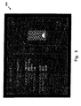
- Fig. 3 shows an example screen shot 300 that may be displayed on the interface unit 120.
- the airdrop status data for a particular mission (Mission XYZ) is listed.
- the airdrop status data includes the cargo type as pallet, the cargo quantity as one (one pallet is to be airdropped on this mission), an airspeed of 130 KTS, an altitude of 400 FT AGL, altitude wind speed of 270/18, time to green light as 2:08, surface winds of 252/8, a surface temperature of 28°C, and a QNH of 29.90. This information is updated as conditions change.
- an aircraft symbol 302 overlays a lateral track 304 that the aircraft is expected to follow for the airdrop.
- the aircraft symbol 302 allows the ground crew to visualize where the aircraft is located with respect to the drop zone. In this example, the aircraft is located between the initial point and the intercept point. Because the aircraft has not reached the stabilization point, the ground crew knows that the guidance computer 12b is still calculating the CARP based on any new airdrop data uplinked to the airborne system 106. Thus, the ground crew may ensure that the ground system 102 is properly functioning and that new data is entered into the interface unit 120 as necessary.
- the screen shot 300 also includes a representation of a drop zone 306 overlaid with point of impact information.
- the drop zone 306 is positioned with respect to the lateral track 304.
- a wind direction symbol 308 is located in the display to show current altitude wind speed and direction. Additional information may also be provided in the screen shot 300.
- Fig. 4 is a flow diagram of a method 400 for aiding airdrop computations.
- GPS and meteorological data are obtained from the drop zone.
- measurements Prior to airdrop, measurements are taken by ground personnel and/or sensors. The measurements include desired point of impact (PI) location, drop zone dimensions, altitude and surface winds, surface temperature, and QNH.
- PI point of impact
- the obtained data is either automatically provided to the interface unit 120 or is manually entered by the ground personnel.
- the data is sent to an aircraft via a data link.
- the data link is established with the inbound aircraft and the drop zone data is uplinked and received by the airborne data link unit 124.
- the airborne data link unit 124 provides the drop zone data to the guidance computer 126.
- a flight plan is adjusted based on the data sent to the aircraft.
- the guidance computer 126 determines if uplinked parameters are enough to change location of the CARP. If so, the CARP is automatically adjusted.
- the flight crew is notified of the adjusted flight plan. Additionally, at block 410, the ground crew is notified of the airdrop status.
- an airdrop is more likely to reach its intended target.
- the supplies, equipment, and/or personnel can be used for their intended purpose.
- providing real time status of the airdrop maneuver to ground personnel allows the ground personnel to anticipate and plan for changes in the mission.
Landscapes
- Engineering & Computer Science (AREA)
- Aviation & Aerospace Engineering (AREA)
- Radar, Positioning & Navigation (AREA)
- Remote Sensing (AREA)
- Physics & Mathematics (AREA)
- General Physics & Mathematics (AREA)
- Automation & Control Theory (AREA)
- Traffic Control Systems (AREA)
- Management, Administration, Business Operations System, And Electronic Commerce (AREA)
Abstract
Description
- The present invention relates generally to airdrops, and more particularly, relates to a system and method for aiding airdrop computations and providing ground personnel with real time status of the airdrop mission.
- An airdrop may be performed to deliver supplies, equipment, and/or personnel to areas that may otherwise be too difficult to reach due to distance, terrain, hostilities, climate, or other reasons. Prior to the airdrop, ground personnel at the drop zone location may take measurements, such as surface and ballistic winds, QNH (a Q code that refers to the barometric altimeter setting that will cause the altimeter to read altitude above mean sea level within a certain defined region), temperature, and desired point of impact in the drop zone. The information obtained by the ground personnel is then transmitted via radio (i.e., voice transmission) to the cargo transport aircraft, where the flight crew manually inputs the airdrop information into a computer. The computer then calculates a Computed Air Release Point (CARP).
- Additionally or alternatively, the flight crew of the cargo transport aircraft may obtain airdrop data by dropping a device that transmits data back to the aircraft. Using the data from the dropped device, the computer calculates a CARP for the airdrop. The aircraft then loops back to complete the airdrop, requiring at least one more pass over the drop zone.
- Unfortunately, with both of these methods for communicating airdrop data to the flight crew, the conditions may have changed after the computer calculated the CARP. As a result, the airdrop may not land in the drop zone. When airdrops do not reach the desired point of impact, disastrous results may occur. For example, humanitarian aid may not reach the people for which it was designed to help. The dropped supplies may be either lost and unused, or used by unintended parties. As another example, personnel may land in hostile areas endangering their lives. The cost of inaccurate airdrops may be immeasurable.
- Thus, it would be beneficial to have a system and method for aiding airdrop computations that result in more accurate airdrops. As a result, supplies and equipment will reach the intended parties, and personnel will arrive where they are needed.
- A system and method for aiding airdrop computations is described. The system includes a ground system, an airborne system, and a data link. The ground system includes a first computer that receives data from a plurality of sensors. The airborne system includes a second computer that calculates a release point for an airdrop maneuver. The data link provides a communication pathway between the ground system and the airborne system. The sensor data received by the first computer is communicated to the second computer via the data link. The second computer calculates the release point based on the sensor data. The second computer may also communicate the status of the airdrop maneuver to the first computer via the data link.
- The plurality of sensors may provide position and meteorological data. The plurality of sensors may include a Global Positioning System. The plurality of sensors may include air data sensors selected from the group consisting of a pilot balloon, a clinometer, an anemometer, a thermometer, and a barometer.
- At least one of the sensors may automatically transmit data to the first computer. Additionally or alternatively, the data from at least one of the sensors may be manually entered into the first computer.
- The first computer may include a wind calculator algorithm. The second computer may also compute a lateral track for the airborne system to follow during the airdrop maneuver. The data link may be a Link 16 data link.
- The system may also include a first data link unit for communicating data between the first computer and the data link, and a second data link unit for communicating data between the second computer and the data link. The first data link unit and the second data link unit may be tactical data link units.
- A method for aiding airdrop computations includes receiving substantially real time sensor data from a drop zone via a data link, calculating a release point for an airdrop maneuver based on the received sensor data, and adjusting a flight plan based on the calculated release point. The method may further include obtaining the sensor data from the drop zone, notifying flight crew of the adjusted flight plan, and providing ground crew a status of the airdrop maneuver via the data link.
- A method for receiving status of an airdrop maneuver includes providing an initial flight plan for an airdrop maneuver to a computer accessible by ground crew, and providing an updated flight plan for the airdrop maneuver to the computer via a data link as the airdrop maneuver progresses. The updated flight plan includes an adjustment to a release point. The adjustment to the release point may be based on substantially real time sensor data communicated to an aircraft via the data link.
- Additionally, the computer may display an aircraft symbol overlaying a lateral track that represents the updated flight plan. The release point may be depicted on the lateral track.
- These as well as other aspects and advantages will become apparent to those of ordinary skill in the art by reading the following detailed description, with reference where appropriate to the accompanying drawings. Further, it is understood that this summary is merely an example and is not intended to limit the scope of the invention as claimed.
- Presently preferred embodiments are described below in conjunction with the appended drawing figures, wherein like reference numerals refer to like elements in the various figures, and wherein:
- Fig. 1 is a block diagram of a system for aiding airdrop computations, according to an example;
- Fig. 2 shows an example lateral track calculated by a guidance computer depicted in Fig. 1;
- Fig. 3 shows an example screen shot that may be displayed on an interface unit depicted in Fig. 1; and
- Fig. 4 is a flow diagram of a method for aiding airdrop computations, according to an example.
- Fig. 1 is a block diagram of a
system 100 for aiding airdrop computations. Thesystem 100 includes aground system 102, adata link 104, and anairborne system 106. Data is exchanged between theground system 102 and theairborne system 106 via thedata link 104. Thesystem 100 provides theairborne system 106 with substantially real time data during an airdrop maneuver to achieve a more accurate airdrop. Additionally, thesystem 100 provides ground personnel with substantially real time status of the airdrop mission. The ground personal are sometimes referred to as the drop zone support team. - The
ground system 102 accumulates substantially real time drop zone Global Positioning System (GPS) and meteorological data for transmitting to theairborne system 106. Theground system 102 receives data from aGPS 108; altitude wind measuring devices, such as a pilot balloon (otherwise known as PIBAL) 110 and aclinometer 112; ananemometer 114 for measuring surface wind; athermometer 116 for measuring surface temperature, and abarometer 118 for measuring QNH. Theground system 102 may include additional sensors. For example, the ground system may include a theodolite and/or a drift scale in lieu of theclinometer 112 to measure the pilot balloon's ascent. - The
ground system 102 also includes aninterface unit 120. Theinterface unit 120 is a computer, such as laptop computer, that includes a display. Theinterface unit 120 receives the data from the sensors 108-118. One or more of the sensors 108-118 may transmit data to theinterface unit 120 directly using either a wired or wireless connection. In this example, theinterface unit 120 and the sensors 108-118 may be described as being part of a common network. Alternatively, the ground personnel may enter data from one or more of the sensors 108-118 into theinterface unit 120 via a keyboard, a microphone, or other user input device. - The
interface unit 120 may also include a wind calculator algorithm for processing the raw data received from the sensors 110-118. The wind calculator algorithm computes the Mean Effective Winds (MEW) for various altitudes using data from thepilot balloon 110. A non-limiting example of a wind calculator algorithm can be found at www.pilotballoon.com/calculat.htm. Theinterface unit 120 provides the raw and/or processed data to a grounddata link unit 122, which provides the data to thedata link 104. - The ground
data link unit 122 may be a tactical data link unit, such as a Multifunctional Information Distribution System (MIDS). MIDS is the North American Treaty Organization (NATO) name for the communication component of Link 16, which is described with reference to thedata link 104. However, other data link units may be used depending on the type ofdata link 104 used in thesystem 100. For example, the grounddata link unit 112 may be a Joint Tactical Radio System (JTRS), which is currently being developed for Armed Forces communication. Like MIDS, the JTRS will host Link 16. - The data link 104 provides a means for transmitting and receiving data between the
ground system 102 and theairborne system 106. Preferably, thedata link 104 is a Link 16 data link, which is a military inter-computer data exchange format of NATO. Link 16 is a secure, high-speed digital data link that can exchange data in substantially real time. However, other data link designs now known or developed in the future may also be used in thesystem 100. - Link 16 uses the joint tactical information distribution system (JTIDS) transmission characteristics and protocols. Airdrop information may be exchanged using these defined transmission characteristics and protocols. For example, Variable Message Format (VMF) utilizing Extensible Markup Language (XML) may be used to format the data exchange.
- The
airborne system 106 is an aircraft that includes an airbornedata link unit 124 and aguidance computer 126. Obviously, theairborne system 106 includes other equipment. For example, theairborne system 106 includes a flight director and/or an autopilot. Theairborne system 106 receives the substantially real time data via the airbornedata link unit 124, which sends the data to theguidance computer 126. Theguidance computer 126 makes adjustments to the airdrop CARP based on this new data. - The airborne
data link unit 124 may be a tactical data link unit, such as a MIDS using Link 16. The airbornedata link unit 124 may be substantially the same as the grounddata link unit 122 located in theground system 102. Alternatively, the airbornedata link unit 124 may have a different design than the grounddata link unit 122, but still be able to communicate with the grounddata link unit 122 via thedata link 104. - The
guidance computer 126 may be a CARP guidance computer, such as a Tactical Flight Management System (FMS) with CARP functionality. Theguidance computer 126 provides guidance commands and/or guidance cues to the aircraft flight director and/of autopilot. Theguidance computer 126 also provides airdrop status information, such as cargo type, cargo amount, green light status, red light status, and completion status to the data link 104 for ground downlink. - The
guidance computer 126 computes a lateral track or path for the aircraft to follow. The lateral track includes waypoint locations, which are adjusted based on the uplinked data. Theguidance computer 126 then controls the aircraft to the adjusted waypoints. - Fig. 2 shows an example
lateral track 200 calculated by theguidance computer 126. Thelateral track 200 has several waypoints. An initial point (IP) 202 is the starting point of thelateral track 200. Theguidance computer 126 guides the aircraft from theinitial point 202 to anintercept point 204. Between theinitial point 202 and theintercept point 204, the aircraft speed and altitude may be adjusted to the desired speed and altitude of the airdrop. Typically, the aircraft reduces speed for the airdrop maneuver. The aircraft may be adjusted to either a higher or lower altitude for the airdrop maneuver. - At the
intercept point 204, the airdrop maneuver begins. When the aircraft reaches astabilization point 206, theguidance computer 126 finalizes the CARP calculation for use in the airdrop maneuver. When the aircraft reaches theCARP 208, a green light in the cargo area of the aircraft is illuminated indicating that the cargo should be dropped. The cargo and/or personnel are dropped from the aircraft until a red light illuminates atpoint 210, indicating the end of the airdrop. - After the airdrop is complete, the guidance computer directs the aircraft to a drop zone escape (DZESC)
point 212. If the airdrop mission is complete, the aircraft is directed to the next waypoint, which may be a start to another mission or to a landing destination. Otherwise, the aircraft may be directed to theinitial point 202 to make another pass at the drop zone. If the airdrop mission is not complete, theguidance computer 126 continues to calculate the CARP with the new data received from theground system 102. Thus, thelateral track 200 for each pass may be different as conditions change. - Additionally, the
airborne system 106 provides real time airdrop status to theground system 102. As a result, the ground crew receives better situational awareness of the airdrop mission. The airdrop status data may include pending and completed cargo drop status, including cargo type and quantity; count down to green light and green light status; red light status; and other airdrop status, such as number of passes and drop altitude. The airdrop status data may be provided to theground system 102 via downlink to the grounddata link unit 122. The grounddata link unit 122 provides the airdrop status data to theinterface unit 120. Theinterface unit 102 may display a graphical representation of the aircraft's position relative to the drop zone. - Fig. 3 shows an example screen shot 300 that may be displayed on the
interface unit 120. On the left side of the screen shot 300, the airdrop status data for a particular mission (Mission XYZ) is listed. In this example, the airdrop status data includes the cargo type as pallet, the cargo quantity as one (one pallet is to be airdropped on this mission), an airspeed of 130 KTS, an altitude of 400 FT AGL, altitude wind speed of 270/18, time to green light as 2:08, surface winds of 252/8, a surface temperature of 28°C, and a QNH of 29.90. This information is updated as conditions change. - On the right side of the screen shot 300. an aircraft symbol 302 overlays a lateral track 304 that the aircraft is expected to follow for the airdrop. The aircraft symbol 302 allows the ground crew to visualize where the aircraft is located with respect to the drop zone. In this example, the aircraft is located between the initial point and the intercept point. Because the aircraft has not reached the stabilization point, the ground crew knows that the guidance computer 12b is still calculating the CARP based on any new airdrop data uplinked to the
airborne system 106. Thus, the ground crew may ensure that theground system 102 is properly functioning and that new data is entered into theinterface unit 120 as necessary. - The screen shot 300 also includes a representation of a drop zone 306 overlaid with point of impact information. The drop zone 306 is positioned with respect to the lateral track 304. A wind direction symbol 308 is located in the display to show current altitude wind speed and direction. Additional information may also be provided in the screen shot 300.
- Fig. 4 is a flow diagram of a
method 400 for aiding airdrop computations. Atblock 402, GPS and meteorological data are obtained from the drop zone. Prior to airdrop, measurements are taken by ground personnel and/or sensors. The measurements include desired point of impact (PI) location, drop zone dimensions, altitude and surface winds, surface temperature, and QNH. The obtained data is either automatically provided to theinterface unit 120 or is manually entered by the ground personnel. - At
block 404, the data is sent to an aircraft via a data link. The data link is established with the inbound aircraft and the drop zone data is uplinked and received by the airbornedata link unit 124. The airbornedata link unit 124 provides the drop zone data to theguidance computer 126. - At
block 406, a flight plan is adjusted based on the data sent to the aircraft. Theguidance computer 126 determines if uplinked parameters are enough to change location of the CARP. If so, the CARP is automatically adjusted. Atblock 408, the flight crew is notified of the adjusted flight plan. Additionally, atblock 410, the ground crew is notified of the airdrop status. - By providing real time data to the airborne system, an airdrop is more likely to reach its intended target. As a result, the supplies, equipment, and/or personnel can be used for their intended purpose. Additionally, providing real time status of the airdrop maneuver to ground personnel, allows the ground personnel to anticipate and plan for changes in the mission.
- It should be understood that the illustrated embodiments are examples only and should not be taken as limiting the scope of the present invention. The claims should not be read as limited to the described order or elements unless stated to that effect. Therefore, all embodiments that come within the scope and spirit of the following claims and equivalents thereto are claimed as the invention.
Claims (10)
- A system for aiding airdrop computations, comprising in combination:a ground system that includes a first computer that receives data from a plurality of sensors; andan airborne system that includes a second computer that calculates a release point for an airdrop maneuver; wherein the ground system and the airborne system communicate via a data link to allow the sensor data received by the first computer to be communicated to the second computer, and wherein the second computer calculates the release point based on the sensor data.
- The system of claim 1, wherein the second computer communicates status of the airdrop maneuver to the first computer via the data link.
- The system of claim 1, wherein the plurality of sensors provides position and meteorological data.
- The system of claim 1, wherein the plurality of sensors includes a Global Positioning System.
- The system of claim 1, wherein the plurality of sensors includes air data sensors selected from the group consisting of a pilot balloon, a clinometer, an anemometer, a thermometer, and a barometer.
- The system of claim 1, wherein at least one of the sensors automatically transmits data to the first computer.
- The system of claim 1, wherein data from at least one of the sensors is manually entered into the first computer.
- The system of claim 1, wherein the first computer includes a wind calculator algorithm.
- The system of claim 1, further comprising a first data link unit for communicating data between the first computer and the data link, and a second data link unit for communicating data between the second computer and the data link.
- The system of claim 1, wherein the second computer computes a lateral track for the airborne system to follow during the airdrop maneuver.
Applications Claiming Priority (1)
| Application Number | Priority Date | Filing Date | Title |
|---|---|---|---|
| US11/503,814 US8271179B2 (en) | 2006-08-14 | 2006-08-14 | System and method for aiding airdrop computations |
Publications (3)
| Publication Number | Publication Date |
|---|---|
| EP1903414A2 true EP1903414A2 (en) | 2008-03-26 |
| EP1903414A3 EP1903414A3 (en) | 2009-10-14 |
| EP1903414B1 EP1903414B1 (en) | 2016-11-30 |
Family
ID=39027480
Family Applications (1)
| Application Number | Title | Priority Date | Filing Date |
|---|---|---|---|
| EP07114102.2A Ceased EP1903414B1 (en) | 2006-08-14 | 2007-08-09 | System and method for aiding airdrop computations |
Country Status (2)
| Country | Link |
|---|---|
| US (1) | US8271179B2 (en) |
| EP (1) | EP1903414B1 (en) |
Cited By (2)
| Publication number | Priority date | Publication date | Assignee | Title |
|---|---|---|---|---|
| EP3474110A1 (en) * | 2017-10-23 | 2019-04-24 | Honeywell International Inc. | A method and system for automatically adjusting airdrop parameters for a dynamic drop zone |
| US10299792B2 (en) | 2014-04-16 | 2019-05-28 | Ethicon Llc | Fastener cartridge comprising non-uniform fasteners |
Families Citing this family (14)
| Publication number | Priority date | Publication date | Assignee | Title |
|---|---|---|---|---|
| US7866527B2 (en) | 2008-02-14 | 2011-01-11 | Ethicon Endo-Surgery, Inc. | Surgical stapling apparatus with interlockable firing system |
| US8346411B1 (en) * | 2009-08-16 | 2013-01-01 | Rockwell Collins, Inc. | Integrated system for providing a journey log display and the automatic reporting thereof |
| US9220501B2 (en) | 2010-09-30 | 2015-12-29 | Ethicon Endo-Surgery, Inc. | Tissue thickness compensators |
| US9301753B2 (en) | 2010-09-30 | 2016-04-05 | Ethicon Endo-Surgery, Llc | Expandable tissue thickness compensator |
| JP6105041B2 (en) | 2012-03-28 | 2017-03-29 | エシコン・エンド−サージェリィ・インコーポレイテッドEthicon Endo−Surgery,Inc. | Tissue thickness compensator containing capsules defining a low pressure environment |
| US8984938B1 (en) * | 2012-06-11 | 2015-03-24 | The Boeing Company | Methods and systems for wind detection |
| US8781719B1 (en) * | 2012-07-02 | 2014-07-15 | The Boeing Company | High-low airdrop wind management |
| US9183516B2 (en) * | 2013-07-25 | 2015-11-10 | The Boeing Company | Systems and methods for locating and prioritizing cargo |
| US9776719B2 (en) * | 2013-09-05 | 2017-10-03 | Raytheon Company | Air-launchable container for deploying air vehicle |
| US9508265B2 (en) | 2014-07-24 | 2016-11-29 | The Charles Stark Draper Laboratory, Inc. | Methods and systems for wind mitigation in autonomous parafoil guidance |
| US10405863B2 (en) | 2015-06-18 | 2019-09-10 | Ethicon Llc | Movable firing beam support arrangements for articulatable surgical instruments |
| US10076326B2 (en) | 2015-09-23 | 2018-09-18 | Ethicon Llc | Surgical stapler having current mirror-based motor control |
| US10088998B2 (en) * | 2017-01-26 | 2018-10-02 | Honeywell International Inc. | Methods and apparatus for dynamically updating drop zone data during flight |
| KR102322098B1 (en) * | 2021-05-17 | 2021-11-05 | 주식회사 보라스카이 | Drone capable of precise dropping |
Family Cites Families (33)
| Publication number | Priority date | Publication date | Assignee | Title |
|---|---|---|---|---|
| US3979086A (en) * | 1974-11-08 | 1976-09-07 | The United States Of America As Represented By The Secretary Of The Army | Rocketed data communication system |
| US4688037A (en) * | 1980-08-18 | 1987-08-18 | Mcdonnell Douglas Corporation | Electromagnetic communications and switching system |
| US5544843A (en) * | 1991-08-01 | 1996-08-13 | The Charles Stark Draper Laboratory, Inc. | Ballistic missile remote targeting system and method |
| US5588620A (en) * | 1992-08-26 | 1996-12-31 | Gilbert; Raymond D. | Radial-force spoiler system |
| US20030193414A1 (en) * | 1993-05-18 | 2003-10-16 | Jones M. Kelly | User-definable communications methods and systems |
| US20030193413A1 (en) * | 1993-05-18 | 2003-10-16 | Jones M. Kelly | Business methods for notification systems |
| US5519618A (en) * | 1993-08-02 | 1996-05-21 | Massachusetts Institute Of Technology | Airport surface safety logic |
| US5374932A (en) * | 1993-08-02 | 1994-12-20 | Massachusetts Institute Of Technology | Airport surface surveillance system |
| US6539336B1 (en) * | 1996-12-12 | 2003-03-25 | Phatrat Technologies, Inc. | Sport monitoring system for determining airtime, speed, power absorbed and other factors such as drop distance |
| FR2729863B1 (en) * | 1995-01-31 | 1997-02-28 | Sextant Avionique | FIRE EXTINGUISHING ASSISTANCE DEVICE FOR WATER BOMBER AIRCRAFT |
| US5904724A (en) * | 1996-01-19 | 1999-05-18 | Margolin; Jed | Method and apparatus for remotely piloting an aircraft |
| US6237496B1 (en) * | 1997-02-26 | 2001-05-29 | Northrop Grumman Corporation | GPS guided munition |
| US5943009A (en) * | 1997-02-27 | 1999-08-24 | Abbott; Anthony Steven | GPS guided munition |
| US6130642A (en) * | 1997-03-04 | 2000-10-10 | The United States Of America As Represented By The Secretary Of The Navy | Method and system to improve GPS navigation |
| US6308043B1 (en) * | 1998-07-23 | 2001-10-23 | Radiometrics Corporation | Wireless communication link quality forecasting |
| US6317029B1 (en) * | 1998-08-07 | 2001-11-13 | Aeroastro, Llc | In situ remote sensing |
| US20030067542A1 (en) * | 2000-10-13 | 2003-04-10 | Monroe David A. | Apparatus for and method of collecting and distributing event data to strategic security personnel and response vehicles |
| US6392692B1 (en) * | 1999-02-25 | 2002-05-21 | David A. Monroe | Network communication techniques for security surveillance and safety system |
| US6545601B1 (en) * | 1999-02-25 | 2003-04-08 | David A. Monroe | Ground based security surveillance system for aircraft and other commercial vehicles |
| US6246320B1 (en) * | 1999-02-25 | 2001-06-12 | David A. Monroe | Ground link with on-board security surveillance system for aircraft and other commercial vehicles |
| US6531965B1 (en) * | 2000-04-11 | 2003-03-11 | Northrop Grumman Corporation | Modular open system architecture for unattended ground sensors |
| CA2390487C (en) * | 2001-06-11 | 2009-02-10 | Robert D. Wiplinger | Gear status indicator aircraft landing system |
| US6549162B1 (en) * | 2001-06-12 | 2003-04-15 | Qualcomm, Inc. | Method and apparatus for transmitting real time data from aircraft to ground stations using a data protocol over a satellite system |
| AU2002334708A1 (en) * | 2001-10-01 | 2003-04-14 | Kline And Walker, Llc | Pfn/trac system faa upgrades for accountable remote and robotics control |
| US7082296B2 (en) * | 2002-04-19 | 2006-07-25 | Northrup Grumann Corporation | Method for sustaining radio frequency (RF) based communications connectivity during network outages |
| US7119716B2 (en) * | 2003-05-28 | 2006-10-10 | Legalview Assets, Limited | Response systems and methods for notification systems for modifying future notifications |
| US20050080520A1 (en) * | 2003-09-22 | 2005-04-14 | Robert Kline | Waste recovery and material handling process to replace the traditional trash transfer station and landfil by extracting reusable material and energy from joined refuse streams to include; office waste, dry waste, wet garbage and the special hazardous material handling of biological, chemical, and nuclear waste |
| US7561069B2 (en) * | 2003-11-12 | 2009-07-14 | Legalview Assets, Limited | Notification systems and methods enabling a response to change particulars of delivery or pickup |
| FR2863372B1 (en) * | 2003-12-04 | 2006-02-10 | Airbus France | METHOD AND SYSTEM FOR AUTOMATICALLY DRIVING AN AIRCRAFT AT THE APPROACH TO A PARACHUTAGE POSITION. |
| FR2863250B1 (en) | 2003-12-04 | 2006-02-10 | Airbus France | METHOD AND DEVICE FOR AIDING PARACHUTAGE |
| US7523892B2 (en) * | 2005-03-21 | 2009-04-28 | Michael Leon Cook | Centripetal reflex method of space launch |
| US7728727B2 (en) * | 2005-05-10 | 2010-06-01 | Honeywell International Inc. | Dynamic inventory during transit |
| US7708222B2 (en) * | 2007-04-27 | 2010-05-04 | Stratocomm Corporation | Long mission tethered aerostat and method of accomplishing |
-
2006
- 2006-08-14 US US11/503,814 patent/US8271179B2/en active Active
-
2007
- 2007-08-09 EP EP07114102.2A patent/EP1903414B1/en not_active Ceased
Non-Patent Citations (1)
| Title |
|---|
| "Precision Airdrop", FLIGHT TEST TECHNIQUES SERIES, vol. 24, December 2005 (2005-12-01) |
Cited By (2)
| Publication number | Priority date | Publication date | Assignee | Title |
|---|---|---|---|---|
| US10299792B2 (en) | 2014-04-16 | 2019-05-28 | Ethicon Llc | Fastener cartridge comprising non-uniform fasteners |
| EP3474110A1 (en) * | 2017-10-23 | 2019-04-24 | Honeywell International Inc. | A method and system for automatically adjusting airdrop parameters for a dynamic drop zone |
Also Published As
| Publication number | Publication date |
|---|---|
| US20080078881A1 (en) | 2008-04-03 |
| EP1903414A3 (en) | 2009-10-14 |
| US8271179B2 (en) | 2012-09-18 |
| EP1903414B1 (en) | 2016-11-30 |
Similar Documents
| Publication | Publication Date | Title |
|---|---|---|
| EP1903414B1 (en) | System and method for aiding airdrop computations | |
| KR101494654B1 (en) | Method and Apparatus for Guiding Unmanned Aerial Vehicle and Method and Apparatus for Controlling Unmanned Aerial Vehicle | |
| EP3602221B1 (en) | Computer-based systems and methods for facilitating aircraft approach | |
| US10094667B2 (en) | Autonomous precision navigation | |
| US7433779B2 (en) | Method of following the course of the flight plan of a cooperative aircraft | |
| EP0498655B1 (en) | Integrated enroute and approach guidance system for aircraft | |
| US10175699B2 (en) | Method for automatically assisting with the landing of an aircraft | |
| RU2383931C1 (en) | Device for assisting aircraft piloting during autonomous runway approach | |
| RU2384889C1 (en) | System for piloting aircraft during at least autonomous runway approach | |
| US8725322B2 (en) | Method and device for updating a target altitude for an emergency descent of an aircraft | |
| US9611053B2 (en) | Method of facilitating the approach to a platform | |
| CN106813900A (en) | A kind of civil airport navigational lighting aid flight check method based on unmanned air vehicle technique | |
| US12297927B2 (en) | Method of operating a vehicle | |
| US7636619B2 (en) | Device for aiding the guidance of a follower aircraft forming part of a patrol, as well as a system for aiding a patrol flight comprising such a device | |
| CN115052812A (en) | Aircraft landing guiding auxiliary system and aircraft landing comprehensive auxiliary system comprising same | |
| US20150375871A1 (en) | Method of facilitating the approach to a platform | |
| US6263263B1 (en) | Altitude correction for aircraft under non-ISA temperature conditions | |
| EP3474110B1 (en) | A method and system for automatically adjusting airdrop parameters for a dynamic drop zone | |
| US12246860B2 (en) | Remote drop zone atmospherics and marking platform | |
| US6505119B2 (en) | Control unit and mission planning station for a manned paragliding system | |
| RU2478523C2 (en) | Method of aircraft control in landing approach | |
| US20070279254A1 (en) | Method and device to assist in the piloting of an aircraft | |
| US20190050001A1 (en) | System and method for precise determination of a remote geo-location in real time | |
| US8463538B2 (en) | Assistance process and device for managing an in-flight refueling | |
| RU2859729C1 (en) | Integrated flight and navigation system |
Legal Events
| Date | Code | Title | Description |
|---|---|---|---|
| PUAI | Public reference made under article 153(3) epc to a published international application that has entered the european phase |
Free format text: ORIGINAL CODE: 0009012 |
|
| AK | Designated contracting states |
Kind code of ref document: A2 Designated state(s): AT BE BG CH CY CZ DE DK EE ES FI FR GB GR HU IE IS IT LI LT LU LV MC MT NL PL PT RO SE SI SK TR |
|
| AX | Request for extension of the european patent |
Extension state: AL BA HR MK YU |
|
| PUAL | Search report despatched |
Free format text: ORIGINAL CODE: 0009013 |
|
| RIC1 | Information provided on ipc code assigned before grant |
Ipc: B64D 1/00 20060101ALI20090828BHEP Ipc: G05D 1/10 20060101AFI20080214BHEP |
|
| AK | Designated contracting states |
Kind code of ref document: A3 Designated state(s): AT BE BG CH CY CZ DE DK EE ES FI FR GB GR HU IE IS IT LI LT LU LV MC MT NL PL PT RO SE SI SK TR |
|
| AX | Request for extension of the european patent |
Extension state: AL BA HR MK RS |
|
| 17P | Request for examination filed |
Effective date: 20100413 |
|
| AKX | Designation fees paid |
Designated state(s): DE FR GB |
|
| 17Q | First examination report despatched |
Effective date: 20100622 |
|
| RAP1 | Party data changed (applicant data changed or rights of an application transferred) |
Owner name: HONEYWELL INTERNATIONAL INC. |
|
| GRAP | Despatch of communication of intention to grant a patent |
Free format text: ORIGINAL CODE: EPIDOSNIGR1 |
|
| INTG | Intention to grant announced |
Effective date: 20160719 |
|
| GRAS | Grant fee paid |
Free format text: ORIGINAL CODE: EPIDOSNIGR3 |
|
| GRAA | (expected) grant |
Free format text: ORIGINAL CODE: 0009210 |
|
| AK | Designated contracting states |
Kind code of ref document: B1 Designated state(s): DE FR GB |
|
| REG | Reference to a national code |
Ref country code: GB Ref legal event code: FG4D |
|
| REG | Reference to a national code |
Ref country code: DE Ref legal event code: R096 Ref document number: 602007048943 Country of ref document: DE |
|
| REG | Reference to a national code |
Ref country code: FR Ref legal event code: PLFP Year of fee payment: 11 |
|
| REG | Reference to a national code |
Ref country code: DE Ref legal event code: R097 Ref document number: 602007048943 Country of ref document: DE |
|
| PLBE | No opposition filed within time limit |
Free format text: ORIGINAL CODE: 0009261 |
|
| STAA | Information on the status of an ep patent application or granted ep patent |
Free format text: STATUS: NO OPPOSITION FILED WITHIN TIME LIMIT |
|
| 26N | No opposition filed |
Effective date: 20170831 |
|
| REG | Reference to a national code |
Ref country code: FR Ref legal event code: PLFP Year of fee payment: 12 |
|
| PGFP | Annual fee paid to national office [announced via postgrant information from national office to epo] |
Ref country code: GB Payment date: 20180831 Year of fee payment: 12 |
|
| PGFP | Annual fee paid to national office [announced via postgrant information from national office to epo] |
Ref country code: DE Payment date: 20181031 Year of fee payment: 12 |
|
| REG | Reference to a national code |
Ref country code: DE Ref legal event code: R119 Ref document number: 602007048943 Country of ref document: DE |
|
| GBPC | Gb: european patent ceased through non-payment of renewal fee |
Effective date: 20190809 |
|
| PG25 | Lapsed in a contracting state [announced via postgrant information from national office to epo] |
Ref country code: DE Free format text: LAPSE BECAUSE OF NON-PAYMENT OF DUE FEES Effective date: 20200303 |
|
| PG25 | Lapsed in a contracting state [announced via postgrant information from national office to epo] |
Ref country code: GB Free format text: LAPSE BECAUSE OF NON-PAYMENT OF DUE FEES Effective date: 20190809 |
|
| PGFP | Annual fee paid to national office [announced via postgrant information from national office to epo] |
Ref country code: FR Payment date: 20220824 Year of fee payment: 16 |
|
| P01 | Opt-out of the competence of the unified patent court (upc) registered |
Effective date: 20230525 |
|
| PG25 | Lapsed in a contracting state [announced via postgrant information from national office to epo] |
Ref country code: FR Free format text: LAPSE BECAUSE OF NON-PAYMENT OF DUE FEES Effective date: 20230831 |