EP1903353A1 - Ultrasound system and method for forming ultrasound images - Google Patents
Ultrasound system and method for forming ultrasound images Download PDFInfo
- Publication number
- EP1903353A1 EP1903353A1 EP07011008A EP07011008A EP1903353A1 EP 1903353 A1 EP1903353 A1 EP 1903353A1 EP 07011008 A EP07011008 A EP 07011008A EP 07011008 A EP07011008 A EP 07011008A EP 1903353 A1 EP1903353 A1 EP 1903353A1
- Authority
- EP
- European Patent Office
- Prior art keywords
- sub
- frames
- scan lines
- scan
- ultrasound
- Prior art date
- Legal status (The legal status is an assumption and is not a legal conclusion. Google has not performed a legal analysis and makes no representation as to the accuracy of the status listed.)
- Granted
Links
Images







Classifications
-
- G—PHYSICS
- G01—MEASURING; TESTING
- G01S—RADIO DIRECTION-FINDING; RADIO NAVIGATION; DETERMINING DISTANCE OR VELOCITY BY USE OF RADIO WAVES; LOCATING OR PRESENCE-DETECTING BY USE OF THE REFLECTION OR RERADIATION OF RADIO WAVES; ANALOGOUS ARRANGEMENTS USING OTHER WAVES
- G01S15/00—Systems using the reflection or reradiation of acoustic waves, e.g. sonar systems
- G01S15/88—Sonar systems specially adapted for specific applications
- G01S15/89—Sonar systems specially adapted for specific applications for mapping or imaging
- G01S15/8906—Short-range imaging systems; Acoustic microscope systems using pulse-echo techniques
- G01S15/8995—Combining images from different aspect angles, e.g. spatial compounding
-
- A—HUMAN NECESSITIES
- A61—MEDICAL OR VETERINARY SCIENCE; HYGIENE
- A61B—DIAGNOSIS; SURGERY; IDENTIFICATION
- A61B8/00—Diagnosis using ultrasonic, sonic or infrasonic waves
-
- G—PHYSICS
- G01—MEASURING; TESTING
- G01S—RADIO DIRECTION-FINDING; RADIO NAVIGATION; DETERMINING DISTANCE OR VELOCITY BY USE OF RADIO WAVES; LOCATING OR PRESENCE-DETECTING BY USE OF THE REFLECTION OR RERADIATION OF RADIO WAVES; ANALOGOUS ARRANGEMENTS USING OTHER WAVES
- G01S15/00—Systems using the reflection or reradiation of acoustic waves, e.g. sonar systems
- G01S15/88—Sonar systems specially adapted for specific applications
- G01S15/89—Sonar systems specially adapted for specific applications for mapping or imaging
- G01S15/8906—Short-range imaging systems; Acoustic microscope systems using pulse-echo techniques
- G01S15/8909—Short-range imaging systems; Acoustic microscope systems using pulse-echo techniques using a static transducer configuration
- G01S15/8915—Short-range imaging systems; Acoustic microscope systems using pulse-echo techniques using a static transducer configuration using a transducer array
- G01S15/8927—Short-range imaging systems; Acoustic microscope systems using pulse-echo techniques using a static transducer configuration using a transducer array using simultaneously or sequentially two or more subarrays or subapertures
-
- G—PHYSICS
- G01—MEASURING; TESTING
- G01S—RADIO DIRECTION-FINDING; RADIO NAVIGATION; DETERMINING DISTANCE OR VELOCITY BY USE OF RADIO WAVES; LOCATING OR PRESENCE-DETECTING BY USE OF THE REFLECTION OR RERADIATION OF RADIO WAVES; ANALOGOUS ARRANGEMENTS USING OTHER WAVES
- G01S5/00—Position-fixing by co-ordinating two or more direction or position line determinations; Position-fixing by co-ordinating two or more distance determinations
- G01S5/18—Position-fixing by co-ordinating two or more direction or position line determinations; Position-fixing by co-ordinating two or more distance determinations using ultrasonic, sonic or infrasonic waves
-
- G—PHYSICS
- G01—MEASURING; TESTING
- G01S—RADIO DIRECTION-FINDING; RADIO NAVIGATION; DETERMINING DISTANCE OR VELOCITY BY USE OF RADIO WAVES; LOCATING OR PRESENCE-DETECTING BY USE OF THE REFLECTION OR RERADIATION OF RADIO WAVES; ANALOGOUS ARRANGEMENTS USING OTHER WAVES
- G01S7/00—Details of systems according to groups G01S13/00, G01S15/00, G01S17/00
- G01S7/52—Details of systems according to groups G01S13/00, G01S15/00, G01S17/00 of systems according to group G01S15/00
- G01S7/52017—Details of systems according to groups G01S13/00, G01S15/00, G01S17/00 of systems according to group G01S15/00 particularly adapted to short-range imaging
- G01S7/52085—Details related to the ultrasound signal acquisition, e.g. scan sequences
Definitions
- the present invention generally relates to an ultrasound system, and more particularly to an ultrasound system and method for forming an ultrasound image.
- An ultrasound system has become an important and popular diagnostic tool since it has a wide range of applications. Specifically, due to its non-invasive and nondestructive nature, the ultrasound system has been extensively used in the medical profession. Modem high-performance ultrasound systems and techniques are commonly used to produce two or three-dimensional diagnostic images of internal features of an object (e.g., human organs).
- an object e.g., human organs
- the probe of an ultrasound system generally includes transducers for transmitting and receiving broadband ultrasound signals.
- ultrasound signals are generated and transmitted to the object.
- Signals reflected from the object and delivered to the transducers which may be referred to as ultrasound echo signals, are electrically transformed.
- ultrasound image data can be generated.
- FIG. 1 shows a geometrical structure of scan lines for the respective transducers in a curved linear probe.
- FIG. 1 shows a geometrical structure of scan lines for the respective transducers in a curved linear probe.
- FIG. 1 when the respective scan lines 21 are extended back to the rear of the transducers 12, there appears a point 30, through which all the scan lines pass (hereinafter referred to as a "common point").
- a common point through which all the scan lines pass
- steering angles of the respective scan lines 21 can be determined once the location of the common point 30 is determined.
- FIG. 2 when the common point 30 moves, the steering angles of the respective scan lines 21 change. Thereafter, by constructing new scan lines 22 according to the newly determined steering angles, an ultrasound image having a wider view angle can be obtained.
- FIG. 1 shows a geometrical structure of scan lines for respective transducers of a curved linear probe
- FIG. 2 shows a geometrical structure of scan lines for respective transducers of a conventional curved linear probe with adjusted steering angles
- FIG. 3 shows a configuration of an ultrasound system constructed in accordance with an embodiment of the present invention
- FIG. 4 shows an example of determining steering angles in accordance with an embodiment of the present invention
- FIGS. 5 to 7 show an example of determining groups of scan lines in accordance with an embodiment of the present invention
- FIGS. 8 to 10 show an example of sub-frames of the respective scan-line groups in accordance with an embodiment of the present invention.
- FIG. 11 shows an example of a frame formed by spatially synthesizing sub-frames in accordance with an embodiment of the present invention.
- An ultrasound system constructed in accordance with an embodiment of the present invention includes a plurality of transducers, a determination unit, a controller and a processor.
- the transducers transmit and receive ultrasound signals along a plurality of scan lines to obtain sub-frames.
- the determination unit locates a common point where extensions of the scan lines with respect to the transducers intersect, and determines a plurality of virtual common points based on the located common point.
- the determination unit determines a plurality of transducer groups, steering angles and a plurality of scan-line groups. Based on the transducer groups, the steering angles and the scan-line groups, the controller selects scan lines corresponding to the changed sub-frames and adjusts steering angles of the selected scan lines as the sub-frame changes.
- the processor synthesizes the sub-frames to form an ultrasound image.
- an ultrasound system 100 constructed in accordance with an embodiment of the present invention includes a probe 110, a scan-line determination unit 120, a beam-former 130, a processor 140 and a display unit 150.
- the probe 110 includes a transducer array 112 comprising a plurality of transducers.
- the probe 110 transmits ultrasound signals to an object along scan lines and receives ultrasound signals reflected by the object.
- the probe 110 may be a curved linear probe.
- the scan-line determination unit 120 includes a steering angle calculation unit 121, a scan-line group determination unit 122 and a controller 123.
- the steering angle calculation unit 121 locates a plurality of virtual common points based on the common point where extensions of original scan lines for the respective transducers intersect. It then partitions a plurality of transducers into several groups based on the number of located virtual common points. Thereafter, the steering angle calculation unit 121 matches virtual common points to the respective transducer groups and calculates adjusted steering angles of the scan lines for the respective transducers.
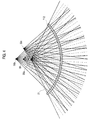
- the steering angle calculation unit 121 may locate: a first virtual common point 30a by moving the common point 30 toward the transducer array 112; a second virtual common point 30b by moving the common point 30 far from the transducer array 112; and a third virtual common point 30c by moving the common point 30 in parallel with the transducer array 112. It may then partition a plurality of scan lines into 3 groups according to the number of the located virtual common points.
- the steering angle calculation unit 121 may determine: transducers ⁇ T 1 , T 4 , T 7 , T 10 , ... ⁇ as a first transducer group; transducers ⁇ T 2 , T 5 , T 8 , T 11 , ... ⁇ as a second transducer group; and transducers ⁇ T 3 , T 6 , T 9 , T 12 , ... ⁇ as a third transducer group.
- the steering angle calculation unit 121 may determine: the first virtual common point 30a as a virtual common point corresponding to the first transducer group; the second virtual common point 30b as a virtual common point corresponding to the second transducer group; and the third virtual common point 30c as a virtual common point corresponding to the third transducer group. Thereafter, the steering angle calculation unit 121 calculates steering angles of the scan lines for the respective transducers based on the location of the corresponding virtual common points.
- the present invention partitions a plurality of transducers into three groups based on three virtual common points
- the present invention is not limited thereto. It is also possible to locate N number of virtual common points and to partition a plurality of transducers T 1 to T n based on the number N of the located virtual common points.
- the plurality of transducers T 1 to T n may be partitioned so that the transducers ⁇ T 1 , T N+1 , T 2N+1 , T 3N+1 , ... ⁇ constitute a first transducer group, the transducers ⁇ T 2 , T N+2 , T 2N+2 , T 3N+2 , ... constitute a second transducer group, and ⁇ T N , T 2N , T 3N , T 4N , ... constitute an Nth transducer group.
- the common point is moved into vertical and horizontal directions to locate a plurality of virtual common points.
- the present invention is not limited thereto. That is, the common point may be moved in various directions to locate a plurality of virtual common points.
- the scan-line group determination unit 122 determines scan-line groups to obtain a plurality of sub-frames. Assume that three virtual common points 30a, 30b and 30c are located by the steering angle calculation unit 121 and transducer groups are determined based on the three located virtual common points 30a, 30b and 30c in accordance with an embodiment of the present invention.
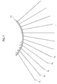
- the scan-line group determination unit 122 may determine, among a plurality of scan lines S 1 to S n : scan lines ⁇ S 1 , S 4 , S 7 , S 10 , ... ⁇ corresponding to the first transducer group as a first scan-line group to obtain a first sub-frame; scan lines ⁇ S 2 , S 5 , S 8 , S 11 , ... ⁇ corresponding to the second transducer group as a second scan-line group to obtain a second sub-frame; and scan lines ⁇ S 3 , S 6 , S 9 , S 12 , ... ⁇ as a third scan-line group to obtain a third sub-frame.
- the present invention is not limited thereto.
- the scan lines S 1 to S n may be partitioned so that the scan lines ⁇ S 1 , S N+1 , S 2N+1 , S 3N+1 , ... ⁇ constitute a first scan-line group, the scan lines ⁇ S 2 , S N+2 , S 2N+2 , S 3N+2 , ... ⁇ constitute a second scan-line group, and ⁇ S N , S 2N , S 3N , S 4N , ... ⁇ constitute an Nth scan-line group.
- the controller 123 performs control whenever the frame changes so that ultrasound signals are transmitted along the scan lines of the scan-line groups corresponding to the respective sub-frames.
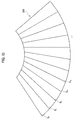
- the controller 123 performs control so that ultrasound signals are transmitted along the respective scan lines ⁇ S 1 , S 4 , S 7 , ..., S n-2 ⁇ of the first scan-line group as shown in FIG. 5.
- the controller 123 further performs control so that ultrasound signals are transmitted along the respective scan lines ⁇ S 2 , S 5 , S 8 , ..., S n-1 ⁇ of the second scan-line group as shown in FIG. 6.
- the ultrasound signals are transmitted along the respective scan lines ⁇ S 3 , S 6 , S 9 , ..., S n ⁇ of the third scan-line group as shown in FIG. 7 in order to obtain a third sub-frame 330 as shown in FIG. 10.
- the controller 123 also controls the processor 140 to synthesize a plurality of sub-frames based on the virtual common points, the steering angles, the transducer groups and the scan-line groups, thereby forming one frame of the ultrasound image.
- the beam-former 130 delays and sums up the ultrasound signals, which are transmitted and received by the transducers along scan lines corresponding to each of the scan-line groups.
- the processor 140 forms one frame by spatially synthesizing a plurality of sub-frames provided by the beam-former 130 under the control of the controller 123. It then forms an ultrasound image signal based on the synthesized frame.
- the processor 140 spatially synthesizes sub-frames 310 to 330 as shown in FIGS. 8 to 10 to form a frame 340 as shown in FIG. 11.
- the processor 140 may perform the synthesizing by calculating average of each pixel (e.g., averaged intensity of each pixel) through a plurality of sub-frames 310 to 330, or by providing different weights on the sub-frames.
- the processor 140 may further perform interpolation processing on each sub-frame using a variety of image interpolation methods before spatially synthesizing the sub-frames.
- the processor 140 may also include a storage unit to temporarily store the sub-frames.
- the display unit 150 receives the ultrasound image signal from the processor 140 and displays the ultrasound image.
- any reference in this specification to "one embodiment,” “an embodiment,” “example embodiment,” etc. means that a particular feature, structure or characteristic described in connection with the embodiment is included in at least one embodiment of the invention.
- the appearances of such phrases in various places in the specification are not necessarily all referring to the same embodiment.
Landscapes
- Engineering & Computer Science (AREA)
- Physics & Mathematics (AREA)
- Radar, Positioning & Navigation (AREA)
- Remote Sensing (AREA)
- Acoustics & Sound (AREA)
- General Physics & Mathematics (AREA)
- Computer Networks & Wireless Communication (AREA)
- Health & Medical Sciences (AREA)
- Life Sciences & Earth Sciences (AREA)
- Radiology & Medical Imaging (AREA)
- Molecular Biology (AREA)
- Pathology (AREA)
- Biophysics (AREA)
- Biomedical Technology (AREA)
- Heart & Thoracic Surgery (AREA)
- Medical Informatics (AREA)
- Nuclear Medicine, Radiotherapy & Molecular Imaging (AREA)
- Surgery (AREA)
- Animal Behavior & Ethology (AREA)
- General Health & Medical Sciences (AREA)
- Public Health (AREA)
- Veterinary Medicine (AREA)
- Ultra Sonic Daignosis Equipment (AREA)
- Investigating Or Analyzing Materials By The Use Of Ultrasonic Waves (AREA)
Abstract
Description
- The present application claims priority from
Korean Patent Application No. 10-2006-0090671 filed on September 19, 2006 - The present invention generally relates to an ultrasound system, and more particularly to an ultrasound system and method for forming an ultrasound image.
- An ultrasound system has become an important and popular diagnostic tool since it has a wide range of applications. Specifically, due to its non-invasive and nondestructive nature, the ultrasound system has been extensively used in the medical profession. Modem high-performance ultrasound systems and techniques are commonly used to produce two or three-dimensional diagnostic images of internal features of an object (e.g., human organs).
- The probe of an ultrasound system generally includes transducers for transmitting and receiving broadband ultrasound signals. When the transducers are electrically stimulated, ultrasound signals are generated and transmitted to the object. Signals reflected from the object and delivered to the transducers, which may be referred to as ultrasound echo signals, are electrically transformed. By performing amplification and signal processing on the transformed electrical signals, ultrasound image data can be generated.
- In particular, a number of ultrasound systems employ a curved linear probe to transmit and receive ultrasound signals. Since the curved linear probe transmits ultrasound signals in radial directions, it can obtain an ultrasound image in an area wider than the size of the probe. FIG. 1 shows a geometrical structure of scan lines for the respective transducers in a curved linear probe. As illustrated in FIG. 1, when the
respective scan lines 21 are extended back to the rear of thetransducers 12, there appears apoint 30, through which all the scan lines pass (hereinafter referred to as a "common point"). Conversely, steering angles of therespective scan lines 21 can be determined once the location of thecommon point 30 is determined. As shown in FIG. 2, when thecommon point 30 moves, the steering angles of therespective scan lines 21 change. Thereafter, by constructingnew scan lines 22 according to the newly determined steering angles, an ultrasound image having a wider view angle can be obtained. - However, in a conventional ultrasound system, gaps formed between the scan lines become greater as the common point moves for a wider view angle. This deteriorates the quality of the ultrasound image, and more particularly the quality of the object located around the center of the ultrasound image.
- Arrangements and embodiments may be described in detail with reference to the following drawings in which like reference numerals refer to like elements and wherein:
- FIG. 1 shows a geometrical structure of scan lines for respective transducers of a curved linear probe;
- FIG. 2 shows a geometrical structure of scan lines for respective transducers of a conventional curved linear probe with adjusted steering angles;
- FIG. 3 shows a configuration of an ultrasound system constructed in accordance with an embodiment of the present invention;
- FIG. 4 shows an example of determining steering angles in accordance with an embodiment of the present invention;
- FIGS. 5 to 7 show an example of determining groups of scan lines in accordance with an embodiment of the present invention;
- FIGS. 8 to 10 show an example of sub-frames of the respective scan-line groups in accordance with an embodiment of the present invention; and
- FIG. 11 shows an example of a frame formed by spatially synthesizing sub-frames in accordance with an embodiment of the present invention.
- A detailed description may be provided with reference to the accompanying drawings. One of ordinary skill in the art may realize that the following description is illustrative only and is not in any way limiting. Other embodiments of the present invention may readily suggest themselves to such skilled persons having the benefit of this disclosure.
- An ultrasound system constructed in accordance with an embodiment of the present invention includes a plurality of transducers, a determination unit, a controller and a processor. The transducers transmit and receive ultrasound signals along a plurality of scan lines to obtain sub-frames. The determination unit locates a common point where extensions of the scan lines with respect to the transducers intersect, and determines a plurality of virtual common points based on the located common point. The determination unit then determines a plurality of transducer groups, steering angles and a plurality of scan-line groups. Based on the transducer groups, the steering angles and the scan-line groups, the controller selects scan lines corresponding to the changed sub-frames and adjusts steering angles of the selected scan lines as the sub-frame changes. The processor synthesizes the sub-frames to form an ultrasound image.
- Hereinafter, an embodiment of the present invention will be described with reference to FIGS. 3 to 11. As shown in FIG. 3, an ultrasound system 100 constructed in accordance with an embodiment of the present invention includes a
probe 110, a scan-line determination unit 120, a beam-former 130, aprocessor 140 and adisplay unit 150. - The
probe 110 includes atransducer array 112 comprising a plurality of transducers. Theprobe 110 transmits ultrasound signals to an object along scan lines and receives ultrasound signals reflected by the object. In an embodiment, theprobe 110 may be a curved linear probe. - The scan-
line determination unit 120 includes a steeringangle calculation unit 121, a scan-linegroup determination unit 122 and acontroller 123. The steeringangle calculation unit 121 locates a plurality of virtual common points based on the common point where extensions of original scan lines for the respective transducers intersect. It then partitions a plurality of transducers into several groups based on the number of located virtual common points. Thereafter, the steeringangle calculation unit 121 matches virtual common points to the respective transducer groups and calculates adjusted steering angles of the scan lines for the respective transducers. - In an embodiment shown in FIG. 4, based on the location of the
common point 30 where extensions of theoriginal scan lines 21 with respect to the respective transducers intersect, the steeringangle calculation unit 121 may locate: a first virtualcommon point 30a by moving thecommon point 30 toward thetransducer array 112; a second virtualcommon point 30b by moving thecommon point 30 far from thetransducer array 112; and a third virtualcommon point 30c by moving thecommon point 30 in parallel with thetransducer array 112. It may then partition a plurality of scan lines into 3 groups according to the number of the located virtual common points. That is, among a plurality of transducers T1 to Tn, the steeringangle calculation unit 121 may determine: transducers {T1, T4, T7, T10, ...} as a first transducer group; transducers {T2, T5, T8, T11, ...}as a second transducer group; and transducers {T3, T6, T9, T12, ...} as a third transducer group. The steeringangle calculation unit 121 may determine: the first virtualcommon point 30a as a virtual common point corresponding to the first transducer group; the second virtualcommon point 30b as a virtual common point corresponding to the second transducer group; and the third virtualcommon point 30c as a virtual common point corresponding to the third transducer group. Thereafter, the steeringangle calculation unit 121 calculates steering angles of the scan lines for the respective transducers based on the location of the corresponding virtual common points. - Although the above embodiment partitions a plurality of transducers into three groups based on three virtual common points, the present invention is not limited thereto. It is also possible to locate N number of virtual common points and to partition a plurality of transducers T1 to Tn based on the number N of the located virtual common points. For example, the plurality of transducers T1 to Tn may be partitioned so that the transducers {T1, TN+1, T2N+1, T3N+1, ...} constitute a first transducer group, the transducers {T2, TN+2, T2N+2, T3N+2, ... constitute a second transducer group, and {TN, T2N, T3N, T4N, ... constitute an Nth transducer group.
- Further, in the above embodiment, the common point is moved into vertical and horizontal directions to locate a plurality of virtual common points. However, the present invention is not limited thereto. That is, the common point may be moved in various directions to locate a plurality of virtual common points.
- The scan-line
group determination unit 122 determines scan-line groups to obtain a plurality of sub-frames. Assume that three virtualcommon points angle calculation unit 121 and transducer groups are determined based on the three located virtualcommon points group determination unit 122 may determine, among a plurality of scan lines S1 to Sn: scan lines {S1, S4, S7, S10, ...} corresponding to the first transducer group as a first scan-line group to obtain a first sub-frame; scan lines {S2, S5, S8, S11, ...}corresponding to the second transducer group as a second scan-line group to obtain a second sub-frame; and scan lines {S3, S6, S9, S12, ...}as a third scan-line group to obtain a third sub-frame. Although the above embodiment describes partitioning a plurality of scan lines into three scan-line groups based on the three virtual common points, the present invention is not limited thereto. For example, it is also possible to partition a plurality of scan lines S1 to Sn based on the number N of located virtual common points. As a further example, the scan lines S1 to Sn may be partitioned so that the scan lines {S1, SN+1, S2N+1, S3N+1, ...} constitute a first scan-line group, the scan lines {S2, SN+2, S2N+2, S3N+2, ...} constitute a second scan-line group, and {SN, S2N, S3N, S4N, ...} constitute an Nth scan-line group. - In order to obtain a plurality of sub-frames, the
controller 123 performs control whenever the frame changes so that ultrasound signals are transmitted along the scan lines of the scan-line groups corresponding to the respective sub-frames. In an embodiment of the present invention, in order to obtain afirst sub-frame 310 as shown in FIG. 8, thecontroller 123 performs control so that ultrasound signals are transmitted along the respective scan lines {S1, S4, S7, ..., Sn-2} of the first scan-line group as shown in FIG. 5. Thecontroller 123 further performs control so that ultrasound signals are transmitted along the respective scan lines {S2, S5, S8, ..., Sn-1} of the second scan-line group as shown in FIG. 6. This is in order to obtain asecond sub-frame 320 as shown in FIG. 9. Further, the ultrasound signals are transmitted along the respective scan lines {S3, S6, S9, ..., Sn} of the third scan-line group as shown in FIG. 7 in order to obtain athird sub-frame 330 as shown in FIG. 10. Thecontroller 123 also controls theprocessor 140 to synthesize a plurality of sub-frames based on the virtual common points, the steering angles, the transducer groups and the scan-line groups, thereby forming one frame of the ultrasound image. - Under the control of the
controller 123, the beam-former 130 delays and sums up the ultrasound signals, which are transmitted and received by the transducers along scan lines corresponding to each of the scan-line groups. Theprocessor 140 forms one frame by spatially synthesizing a plurality of sub-frames provided by the beam-former 130 under the control of thecontroller 123. It then forms an ultrasound image signal based on the synthesized frame. In an embodiment of the present invention, theprocessor 140 spatially synthesizessub-frames 310 to 330 as shown in FIGS. 8 to 10 to form aframe 340 as shown in FIG. 11. In such a case, theprocessor 140 may perform the synthesizing by calculating average of each pixel (e.g., averaged intensity of each pixel) through a plurality ofsub-frames 310 to 330, or by providing different weights on the sub-frames. Theprocessor 140 may further perform interpolation processing on each sub-frame using a variety of image interpolation methods before spatially synthesizing the sub-frames. Theprocessor 140 may also include a storage unit to temporarily store the sub-frames. Thedisplay unit 150 receives the ultrasound image signal from theprocessor 140 and displays the ultrasound image. - Any reference in this specification to "one embodiment," "an embodiment," "example embodiment," etc., means that a particular feature, structure or characteristic described in connection with the embodiment is included in at least one embodiment of the invention. The appearances of such phrases in various places in the specification are not necessarily all referring to the same embodiment. Further, when a particular feature, structure or characteristic is described in connection with any embodiment, it is submitted that it is within the purview of one skilled in the art to affect such feature, structure or characteristic in connection with other ones of the embodiments.
- Although embodiments have been described with reference to a number of illustrative embodiments thereof, it should be understood that numerous other modifications and embodiments can be devised by those skilled in the art that will fall within the spirit and scope of the principles of this disclosure. More particularly, various variations and modifications are possible in the component parts and/or arrangements of the subject combination arrangement within the scope of the disclosure, the drawings and the appended claims. For example, although the embodiments have been described as employing a curved linear probe, the present invention is not limited thereto, and it is also possible to use a linear probe, in which case a plurality of virtual common points may be formed by moving a common point located in an infinite point. In addition to variations and modifications in the component parts and/or arrangements, alternative uses will also be apparent to those skilled in the art.
Claims (8)
- An ultrasound system for forming an ultrasound image by using a plurality of sub-frames, comprising:a plurality of transducers for transmitting and receiving ultrasound signals along a plurality of scan lines to obtain sub-frames;a determination unit for locating a common point where extensions of the scan lines with respect to the transducers intersect and determine a plurality of virtual common points based on the located common point, the determination unit further being configured to determine a plurality of transducer groups, steering angles and a plurality of scan-line groups;a controller for being responsive to a change of the sub-frames to select scan lines corresponding to the changed sub-frame and adjust steering angles of the selected scan lines based on the plurality of transducer groups, the steering angles and the plurality of scan-line groups; anda processor for synthesizing the plurality of sub-frames to form an ultrasound image.
- The ultrasound system of Claim 1, wherein the determination unit includes:a first determination unit for determining the plurality of transducer groups by grouping the plurality of transducers according to the number of the virtual common points;a second determination unit for matching the virtual common points with the plurality of transducer groups and determine the steering angles of the scan lines for the respective transducers; anda third determination unit for determining the plurality of scan-line groups by grouping the scan lines corresponding to the respective transducer groups.
- The ultrasound system of Claim 1, wherein the processor includes:a unit for calculating an averaged intensity of each pixel through the plurality of sub-frames and form the ultrasound image by synthesizing the plurality of sub-frames based on the calculated average intensity.
- The ultrasound system of Claim 1, wherein the processor includes:a unit for providing different weights on the plurality of sub-frames and form the ultrasound image by synthesizing the plurality of sub-frames provided with the different weights.
- A method of forming an ultrasound image by using a plurality of sub-frames formed with a plurality of transducers to transmit and receive ultrasound signals along a plurality of scan lines, comprising the steps of:(a) determining a plurality of virtual common points based on a common point where extensions of a plurality of scan lines intersect;(b) determining a plurality of transducer groups, steering angles and a plurality of scan-line groups based on the plurality of virtual common points;(c) in response to a change of sub-frames, selecting scan lines corresponding to the changed sub-frame and adjusting steering angles of the selected scan lines based on the plurality of transducer groups, the steering angles and the plurality of scan-line groups;(d) forming a plurality of sub-frames by transmitting and receiving ultrasound signals along the scan lines with the adjusted steering angles; and(e) forming an ultrasound image by synthesizing the plurality of sub-frames.
- The method of Claim 5, wherein the step (b) includes:(b1) determining the plurality of transducer groups by grouping a plurality of transducers according to the number of the virtual common points;(b2) matching the virtual common points with the plurality of transducer groups and determining the steering angles of the scan lines for the respective transducers; and(b3) determining the plurality of scan-line groups corresponding to the respective transducer groups.
- The method of Claim 5, wherein the step (e) includes:calculating averaged intensity of each pixel through the plurality of sub-frames and forming the ultrasound image by synthesizing the plurality of sub-frames based on the calculated average intensity.
- The method of Claim 5, wherein the step (e) includes:providing different weights on the plurality of sub-frames and forming the ultrasound image by synthesizing the plurality of sub-frames provided with the different weights.
Applications Claiming Priority (1)
| Application Number | Priority Date | Filing Date | Title |
|---|---|---|---|
| KR1020060090671A KR100923026B1 (en) | 2006-09-19 | 2006-09-19 | Ultrasound System and Method for Forming Ultrasound Images |
Publications (2)
| Publication Number | Publication Date |
|---|---|
| EP1903353A1 true EP1903353A1 (en) | 2008-03-26 |
| EP1903353B1 EP1903353B1 (en) | 2014-05-14 |
Family
ID=38721460
Family Applications (1)
| Application Number | Title | Priority Date | Filing Date |
|---|---|---|---|
| EP07011008.5A Active EP1903353B1 (en) | 2006-09-19 | 2007-06-05 | Ultrasound system and method for forming ultrasound images |
Country Status (4)
| Country | Link |
|---|---|
| US (1) | US7766835B2 (en) |
| EP (1) | EP1903353B1 (en) |
| JP (1) | JP4893488B2 (en) |
| KR (1) | KR100923026B1 (en) |
Cited By (4)
| Publication number | Priority date | Publication date | Assignee | Title |
|---|---|---|---|---|
| EP2187813A4 (en) * | 2007-09-12 | 2011-03-16 | Sonosite Inc | SYSTEM AND METHOD FOR SPATIAL COMBINATION USING PHASE CONTROL NETWORKS |
| JP2012086007A (en) * | 2010-10-19 | 2012-05-10 | Samsung Medison Co Ltd | Ultrasonic system and method for providing ultrasonic space combined video based on central line of ultrasonic image ultrasonic image |
| CN102895000A (en) * | 2012-11-06 | 2013-01-30 | 重庆大学 | Double-focusing beamforming method based on self-adaptive weighting |
| EP2296004A3 (en) * | 2009-09-02 | 2013-07-24 | Medison Co., Ltd. | Ultrasound system and method for providing an ultrasound spatial compound image considering steering angle |
Families Citing this family (8)
| Publication number | Priority date | Publication date | Assignee | Title |
|---|---|---|---|---|
| KR101175402B1 (en) * | 2009-08-31 | 2012-08-20 | 삼성메디슨 주식회사 | Ultrasound system and method for setting steering of scanlines based on virtual transducer element |
| KR101120820B1 (en) | 2009-11-19 | 2012-03-22 | 삼성메디슨 주식회사 | Ultrasound system and method for providing ultrasound spatial compound image |
| KR101175497B1 (en) | 2009-11-19 | 2012-08-20 | 삼성메디슨 주식회사 | Ultrasound system and method for providing ultrasound spatial compound iamge |
| KR101031504B1 (en) | 2009-11-19 | 2011-06-14 | 삼성메디슨 주식회사 | Ultrasound system and method for providing ultrasonic spatial composite image |
| KR101202510B1 (en) * | 2010-10-20 | 2012-11-20 | 삼성메디슨 주식회사 | Ultrasound system and method for providing ultrasound spatial compound image based on phased array probe |
| KR102120796B1 (en) * | 2014-05-13 | 2020-06-09 | 삼성전자주식회사 | A beamforming apparatus, a method for forming beams, an ultrasonic imaging apparatus and an ultrasonic probe |
| KR102438119B1 (en) * | 2015-10-16 | 2022-08-31 | 삼성전자주식회사 | Ultrasound device and ultrasound imaging method |
| KR20210050375A (en) | 2019-10-28 | 2021-05-07 | 염형진 | Peripheral Recognition Device Using Ultrasonic Sensors |
Citations (5)
| Publication number | Priority date | Publication date | Assignee | Title |
|---|---|---|---|---|
| US5261408A (en) * | 1990-02-12 | 1993-11-16 | Acuson Corporation | Variable origin-variable acoustic scanning method and apparatus |
| US6174286B1 (en) * | 1998-11-25 | 2001-01-16 | Acuson Corporation | Medical diagnostic ultrasound method and system for element switching |
| US6508770B1 (en) * | 2001-03-08 | 2003-01-21 | Acuson Corporation | Aperture compounding for medical imaging |
| US20040054284A1 (en) * | 2002-09-13 | 2004-03-18 | Acuson Corporation | Overlapped scanning for multi-directional compounding of ultrasound images |
| US6814701B1 (en) * | 2003-04-16 | 2004-11-09 | Aloka Co., Ltd. | Method and apparatus for ultrasound diagnostic imaging |
Family Cites Families (8)
| Publication number | Priority date | Publication date | Assignee | Title |
|---|---|---|---|---|
| US4159462A (en) * | 1977-08-18 | 1979-06-26 | General Electric Company | Ultrasonic multi-sector scanner |
| JP2557410B2 (en) * | 1987-09-22 | 1996-11-27 | 株式会社東芝 | Ultrasonic Doppler blood flow imaging device |
| US5235986A (en) | 1990-02-12 | 1993-08-17 | Acuson Corporation | Variable origin-variable angle acoustic scanning method and apparatus for a curved linear array |
| JPH07120244A (en) * | 1993-10-25 | 1995-05-12 | Hitachi Medical Corp | Visualizing method in supersonic photographing device |
| US5899861A (en) * | 1995-03-31 | 1999-05-04 | Siemens Medical Systems, Inc. | 3-dimensional volume by aggregating ultrasound fields of view |
| US6709395B2 (en) * | 2002-06-25 | 2004-03-23 | Koninklijke Philips Electronics N.V. | System and method for electronically altering ultrasound scan line origin for a three-dimensional ultrasound system |
| US20050131295A1 (en) * | 2003-12-11 | 2005-06-16 | Koninklijke Philips Electronics N.V. | Volumetric ultrasound imaging system using two-dimensional array transducer |
| KR101120675B1 (en) * | 2005-08-26 | 2012-03-30 | 삼성메디슨 주식회사 | Method of Compounding an Ultrasound Image Using a Spatial Compounding |
-
2006
- 2006-09-19 KR KR1020060090671A patent/KR100923026B1/en active Active
-
2007
- 2007-06-05 EP EP07011008.5A patent/EP1903353B1/en active Active
- 2007-06-07 US US11/759,703 patent/US7766835B2/en active Active
- 2007-06-15 JP JP2007158418A patent/JP4893488B2/en not_active Expired - Fee Related
Patent Citations (5)
| Publication number | Priority date | Publication date | Assignee | Title |
|---|---|---|---|---|
| US5261408A (en) * | 1990-02-12 | 1993-11-16 | Acuson Corporation | Variable origin-variable acoustic scanning method and apparatus |
| US6174286B1 (en) * | 1998-11-25 | 2001-01-16 | Acuson Corporation | Medical diagnostic ultrasound method and system for element switching |
| US6508770B1 (en) * | 2001-03-08 | 2003-01-21 | Acuson Corporation | Aperture compounding for medical imaging |
| US20040054284A1 (en) * | 2002-09-13 | 2004-03-18 | Acuson Corporation | Overlapped scanning for multi-directional compounding of ultrasound images |
| US6814701B1 (en) * | 2003-04-16 | 2004-11-09 | Aloka Co., Ltd. | Method and apparatus for ultrasound diagnostic imaging |
Cited By (8)
| Publication number | Priority date | Publication date | Assignee | Title |
|---|---|---|---|---|
| EP2187813A4 (en) * | 2007-09-12 | 2011-03-16 | Sonosite Inc | SYSTEM AND METHOD FOR SPATIAL COMBINATION USING PHASE CONTROL NETWORKS |
| US8137278B2 (en) | 2007-09-12 | 2012-03-20 | Sonosite, Inc. | System and method for spatial compounding using phased arrays |
| EP2296004A3 (en) * | 2009-09-02 | 2013-07-24 | Medison Co., Ltd. | Ultrasound system and method for providing an ultrasound spatial compound image considering steering angle |
| JP2012086007A (en) * | 2010-10-19 | 2012-05-10 | Samsung Medison Co Ltd | Ultrasonic system and method for providing ultrasonic space combined video based on central line of ultrasonic image ultrasonic image |
| EP2444821A3 (en) * | 2010-10-19 | 2013-11-13 | Samsung Medison Co., Ltd. | Providing an ultrasound spatial compound image based on center lines of ultrasound images in an ultrasound system |
| US9151841B2 (en) | 2010-10-19 | 2015-10-06 | Samsung Medison Co., Ltd. | Providing an ultrasound spatial compound image based on center lines of ultrasound images in an ultrasound system |
| CN102895000A (en) * | 2012-11-06 | 2013-01-30 | 重庆大学 | Double-focusing beamforming method based on self-adaptive weighting |
| CN102895000B (en) * | 2012-11-06 | 2014-06-18 | 重庆大学 | Double-focusing beamforming method based on self-adaptive weighting |
Also Published As
| Publication number | Publication date |
|---|---|
| JP2008073507A (en) | 2008-04-03 |
| KR100923026B1 (en) | 2009-10-22 |
| US7766835B2 (en) | 2010-08-03 |
| KR20080025903A (en) | 2008-03-24 |
| JP4893488B2 (en) | 2012-03-07 |
| EP1903353B1 (en) | 2014-05-14 |
| US20080071175A1 (en) | 2008-03-20 |
Similar Documents
| Publication | Publication Date | Title |
|---|---|---|
| US7766835B2 (en) | Ultrasound system and method for forming ultrasound images | |
| US6276211B1 (en) | Methods and systems for selective processing of transmit ultrasound beams to display views of selected slices of a volume | |
| JP4795675B2 (en) | Medical ultrasound system | |
| US7927276B2 (en) | Apparatus and method for forming an ultrasound image | |
| US10976422B2 (en) | Ultrasound imaging methods and systems | |
| EP2444821B1 (en) | Providing an ultrasound spatial compound image based on center lines of ultrasound images in an ultrasound system | |
| EP1914567A2 (en) | Apparatus and method for forming an ultrasound image | |
| US11602324B2 (en) | Flow imaging processing method and ultrasound imaging device | |
| US7789832B2 (en) | Ultrasound system and method for controlling steering angles of scan lines | |
| JP2002325768A (en) | Refraction delay error correction using agile beamformer | |
| EP1898233B1 (en) | Ultrasound system and method for controlling scan lines | |
| US8216141B2 (en) | Ultrasound system and method for forming BC-mode image | |
| JP4278343B2 (en) | 3D ultrasound imaging system | |
| CN114072063B (en) | Ultrasonic three-dimensional imaging method and device | |
| JP3474278B2 (en) | Ultrasound diagnostic equipment | |
| JP3174450B2 (en) | Ultrasound diagnostic equipment | |
| KR101300646B1 (en) | Apparatus and method for processing a 3-dimensional ultrasound image | |
| JP2784788B2 (en) | Ultrasound diagnostic equipment | |
| US20240085557A1 (en) | Coherent matrix of digital imaging systems on chip | |
| JP3340695B2 (en) | Ultrasound diagnostic equipment | |
| JP2003334193A (en) | Ultrasonic diagnostic equipment and ultrasonic image forming method |
Legal Events
| Date | Code | Title | Description |
|---|---|---|---|
| PUAI | Public reference made under article 153(3) epc to a published international application that has entered the european phase |
Free format text: ORIGINAL CODE: 0009012 |
|
| AK | Designated contracting states |
Kind code of ref document: A1 Designated state(s): AT BE BG CH CY CZ DE DK EE ES FI FR GB GR HU IE IS IT LI LT LU LV MC MT NL PL PT RO SE SI SK TR |
|
| AX | Request for extension of the european patent |
Extension state: AL BA HR MK YU |
|
| 17P | Request for examination filed |
Effective date: 20080613 |
|
| 17Q | First examination report despatched |
Effective date: 20080714 |
|
| AKX | Designation fees paid |
Designated state(s): DE FR IT |
|
| GRAP | Despatch of communication of intention to grant a patent |
Free format text: ORIGINAL CODE: EPIDOSNIGR1 |
|
| INTG | Intention to grant announced |
Effective date: 20131031 |
|
| GRAS | Grant fee paid |
Free format text: ORIGINAL CODE: EPIDOSNIGR3 |
|
| RAP1 | Party data changed (applicant data changed or rights of an application transferred) |
Owner name: SAMSUNG MEDISON CO., LTD. |
|
| GRAA | (expected) grant |
Free format text: ORIGINAL CODE: 0009210 |
|
| AK | Designated contracting states |
Kind code of ref document: B1 Designated state(s): DE FR IT |
|
| REG | Reference to a national code |
Ref country code: DE Ref legal event code: R096 Ref document number: 602007036659 Country of ref document: DE Effective date: 20140626 |
|
| RAP2 | Party data changed (patent owner data changed or rights of a patent transferred) |
Owner name: SAMSUNG MEDISON CO., LTD. |
|
| REG | Reference to a national code |
Ref country code: DE Ref legal event code: R097 Ref document number: 602007036659 Country of ref document: DE |
|
| PLBE | No opposition filed within time limit |
Free format text: ORIGINAL CODE: 0009261 |
|
| STAA | Information on the status of an ep patent application or granted ep patent |
Free format text: STATUS: NO OPPOSITION FILED WITHIN TIME LIMIT |
|
| 26N | No opposition filed |
Effective date: 20150217 |
|
| REG | Reference to a national code |
Ref country code: DE Ref legal event code: R097 Ref document number: 602007036659 Country of ref document: DE Effective date: 20150217 |
|
| REG | Reference to a national code |
Ref country code: FR Ref legal event code: PLFP Year of fee payment: 10 |
|
| REG | Reference to a national code |
Ref country code: FR Ref legal event code: PLFP Year of fee payment: 11 |
|
| REG | Reference to a national code |
Ref country code: FR Ref legal event code: PLFP Year of fee payment: 12 |
|
| PGFP | Annual fee paid to national office [announced via postgrant information from national office to epo] |
Ref country code: DE Payment date: 20250508 Year of fee payment: 19 |
|
| PGFP | Annual fee paid to national office [announced via postgrant information from national office to epo] |
Ref country code: IT Payment date: 20250512 Year of fee payment: 19 |
|
| PGFP | Annual fee paid to national office [announced via postgrant information from national office to epo] |
Ref country code: FR Payment date: 20250513 Year of fee payment: 19 |