EP1903335A1 - Method for the detection and preventive control of defects in parts that are made from composite materials - Google Patents
Method for the detection and preventive control of defects in parts that are made from composite materials Download PDFInfo
- Publication number
- EP1903335A1 EP1903335A1 EP05765625A EP05765625A EP1903335A1 EP 1903335 A1 EP1903335 A1 EP 1903335A1 EP 05765625 A EP05765625 A EP 05765625A EP 05765625 A EP05765625 A EP 05765625A EP 1903335 A1 EP1903335 A1 EP 1903335A1
- Authority
- EP
- European Patent Office
- Prior art keywords
- preventive
- areas
- composite material
- defect detection
- material parts
- Prior art date
- Legal status (The legal status is an assumption and is not a legal conclusion. Google has not performed a legal analysis and makes no representation as to the accuracy of the status listed.)
- Granted
Links
- 238000000034 method Methods 0.000 title claims abstract description 54
- 230000007547 defect Effects 0.000 title claims abstract description 49
- 230000003449 preventive effect Effects 0.000 title claims abstract description 27
- 238000001514 detection method Methods 0.000 title claims abstract description 19
- 239000002131 composite material Substances 0.000 title claims abstract description 13
- 230000008569 process Effects 0.000 claims abstract description 53
- 230000004075 alteration Effects 0.000 claims abstract description 18
- 238000007689 inspection Methods 0.000 claims abstract description 14
- 238000004519 manufacturing process Methods 0.000 claims abstract description 14
- 238000005070 sampling Methods 0.000 claims abstract description 6
- 238000004458 analytical method Methods 0.000 claims description 11
- 230000035945 sensitivity Effects 0.000 claims description 7
- 238000009826 distribution Methods 0.000 description 4
- 238000002592 echocardiography Methods 0.000 description 4
- 230000009467 reduction Effects 0.000 description 4
- 230000032798 delamination Effects 0.000 description 3
- 230000001066 destructive effect Effects 0.000 description 3
- 238000005259 measurement Methods 0.000 description 3
- 238000007619 statistical method Methods 0.000 description 3
- 230000009471 action Effects 0.000 description 2
- 230000002238 attenuated effect Effects 0.000 description 2
- 230000006399 behavior Effects 0.000 description 2
- 238000010586 diagram Methods 0.000 description 2
- 238000001914 filtration Methods 0.000 description 2
- 230000008439 repair process Effects 0.000 description 2
- 244000025254 Cannabis sativa Species 0.000 description 1
- 238000003070 Statistical process control Methods 0.000 description 1
- 230000005540 biological transmission Effects 0.000 description 1
- 230000007423 decrease Effects 0.000 description 1
- 230000003247 decreasing effect Effects 0.000 description 1
- 230000007812 deficiency Effects 0.000 description 1
- 230000002950 deficient Effects 0.000 description 1
- 230000000694 effects Effects 0.000 description 1
- 230000014509 gene expression Effects 0.000 description 1
- 238000012986 modification Methods 0.000 description 1
- 230000004048 modification Effects 0.000 description 1
- 238000012544 monitoring process Methods 0.000 description 1
- 230000003989 repetitive behavior Effects 0.000 description 1
- 208000013406 repetitive behavior Diseases 0.000 description 1
- 230000003252 repetitive effect Effects 0.000 description 1
- 238000003860 storage Methods 0.000 description 1
- 230000035899 viability Effects 0.000 description 1
Images




Classifications
-
- G—PHYSICS
- G01—MEASURING; TESTING
- G01N—INVESTIGATING OR ANALYSING MATERIALS BY DETERMINING THEIR CHEMICAL OR PHYSICAL PROPERTIES
- G01N29/00—Investigating or analysing materials by the use of ultrasonic, sonic or infrasonic waves; Visualisation of the interior of objects by transmitting ultrasonic or sonic waves through the object
- G01N29/44—Processing the detected response signal, e.g. electronic circuits specially adapted therefor
- G01N29/449—Statistical methods not provided for in G01N29/4409, e.g. averaging, smoothing and interpolation
-
- G—PHYSICS
- G01—MEASURING; TESTING
- G01N—INVESTIGATING OR ANALYSING MATERIALS BY DETERMINING THEIR CHEMICAL OR PHYSICAL PROPERTIES
- G01N29/00—Investigating or analysing materials by the use of ultrasonic, sonic or infrasonic waves; Visualisation of the interior of objects by transmitting ultrasonic or sonic waves through the object
- G01N29/04—Analysing solids
- G01N29/043—Analysing solids in the interior, e.g. by shear waves
-
- G—PHYSICS
- G01—MEASURING; TESTING
- G01N—INVESTIGATING OR ANALYSING MATERIALS BY DETERMINING THEIR CHEMICAL OR PHYSICAL PROPERTIES
- G01N29/00—Investigating or analysing materials by the use of ultrasonic, sonic or infrasonic waves; Visualisation of the interior of objects by transmitting ultrasonic or sonic waves through the object
- G01N29/44—Processing the detected response signal, e.g. electronic circuits specially adapted therefor
- G01N29/4454—Signal recognition, e.g. specific values or portions, signal events, signatures
-
- G—PHYSICS
- G01—MEASURING; TESTING
- G01N—INVESTIGATING OR ANALYSING MATERIALS BY DETERMINING THEIR CHEMICAL OR PHYSICAL PROPERTIES
- G01N29/00—Investigating or analysing materials by the use of ultrasonic, sonic or infrasonic waves; Visualisation of the interior of objects by transmitting ultrasonic or sonic waves through the object
- G01N29/44—Processing the detected response signal, e.g. electronic circuits specially adapted therefor
- G01N29/4472—Mathematical theories or simulation
-
- G—PHYSICS
- G01—MEASURING; TESTING
- G01N—INVESTIGATING OR ANALYSING MATERIALS BY DETERMINING THEIR CHEMICAL OR PHYSICAL PROPERTIES
- G01N2291/00—Indexing codes associated with group G01N29/00
- G01N2291/02—Indexing codes associated with the analysed material
- G01N2291/023—Solids
- G01N2291/0231—Composite or layered materials
-
- G—PHYSICS
- G01—MEASURING; TESTING
- G01N—INVESTIGATING OR ANALYSING MATERIALS BY DETERMINING THEIR CHEMICAL OR PHYSICAL PROPERTIES
- G01N2291/00—Indexing codes associated with group G01N29/00
- G01N2291/04—Wave modes and trajectories
- G01N2291/044—Internal reflections (echoes), e.g. on walls or defects
-
- G—PHYSICS
- G01—MEASURING; TESTING
- G01N—INVESTIGATING OR ANALYSING MATERIALS BY DETERMINING THEIR CHEMICAL OR PHYSICAL PROPERTIES
- G01N2291/00—Indexing codes associated with group G01N29/00
- G01N2291/26—Scanned objects
- G01N2291/269—Various geometry objects
- G01N2291/2694—Wings or other aircraft parts
Definitions
- the present invention refers to a preventive defect detection and control process in composite material parts carried out within the non-destructive inspection of composite material parts, and more particularly of parts used in aircraft.
- any reparable defect is detected during inspection it is repaired, and a corrective action is then established in the part manufacturing process so that the defect does not re-occur. It must be taken into account that not all defects are reparable since it may occur that a defect or a group of them generate "unserviceable parts", according to unacceptable criteria for size, occupied area or type of inspection of the area in which they are located.
- the process in turn requires parts or areas of the parts to be inspected where the likeliness of defects may be very low, with the subsequent cost increase.
- the present invention proposes a preventive defect detection and control process within the field of non-destructive inspection of mass produced composite material parts, comprising the following steps for each manufactured part:
- the process according to the invention has a preventive purpose and a required inspection reduction purpose.
- the preventive analysis is based on statistical process control by means of using control charts of the backwall echo attenuation and intermediate echo amplitude signals, which signals may be considered "key signals" due to their high occurrence and variation associated costs (repairs, HNCs).
- the first step 100 of the preventive defect detection and control process in composite material parts according to the present invention is automatic data acquisition.
- control variables used in the process for detecting "potentially preventive" porosity defects are the backwall echo and the intermediate echo and the values which they acquire are:
- This process could likewise control any defect initially considered to be “not preventive” (delamination, foreign objects, debonding %), monitoring the "standard” and “non-random” patterns associated to their ultrasonic echo variation in “classic” graphs, which is not the case in the corresponding improved sensitivity charts / Time weighted charts (since these defects are not usually preventable).
- Data acquisition is carried out by means of a known machine 1 transmitting an ultrasonic signal 5 on a part 3 and capturing the bounced signal 7 along its thickness T.
- FIG. 3 show the ultrasonic energy U variation of the signal along thickness T of the part, and it can be seen that the backwall echo 9 is attenuated with respect to the entrance eco (or backwall calibrated), generally indicating the existence of an overall porosity defect in the part when critical attenuation values are reached (tolerance) unless there are significant intermediate echoes (which represent another type of defects) or identification of attenuation signals inherent to the process and not the defect.
- the mentioned values are obtained automatically in each inspected part for one or several areas thereof, of constant thickness, subdivided into cells. Thickness uniformity in the analyzed cell allows filtering those "false” attenuations caused by guided bouncing of the ultrasonic signal in sloping areas or discontinuous changes on thickness.
- the analyzed areas will be those in which the corrective study has reflected the high defect generation probability (repetitive behaviors).
- the entire part may also be analyzed when process randomness generates defects in historically "healthy" areas.
- Each basic cell of the meshing defined by area includes the existing attenuation and intermediate echo values as the machine caliper tracks and inspects its associated area.
- Each inspected "point" or “basic area”, usually 4 mm 2 corresponds to a piece of data or measurement within the cell, including more or less values according to their basic size.
- the basic cell size for each analyzed area or zone with constant thickness will correspond to the software overflow - detection capability compromise, being standard practice to search for the largest sizes "possible” in the attempt to generate a "healthy” area in the cell when the defect evolves in said cell.
- the standard deviation will thus provide an additional efficient statistical alarm due to any potential defect generation.
- the process herein proposed could therefore obtain those statistically representative parameters (mean, mode, median, standard deviation and whole population) of all the values obtained in the cell.
- the data acquisition step 100 can be carried out within the part inspection process aimed at determining part compliance or non-compliance as a specific action of the process according to the present invention.
- the second step 110 of the process is the storage of the mentioned parameters of each cell in a database associated to a plurality of index data, such as the following:
- Attenuation values exceeding the maximum allowed by the "gate” chosen in the machine will not be included in order to avoid noise, let's take for example the approximate 18 dB under an 20% gate screen height for the backwall echo, upper tolerance limit representative of the "already" generated overall porosity defect. Should there be significant attenuation or intermediate echo values not related with the defect and "assignable" to different factors such as roughness, dirt or edge effect, said data will be acquired but will not be taken into account in the subsequent statistical analysis.
- the overall porosity study range is the one indicated by the If interval, in which the represented attenuation value of the backwall echo Eb is found, not being possible to include values exceeding the limit set in the machine (gate Ls).
- the range If will be defined by the maximum screen height of the backwall echo when there is no attenuation (aspect generally related to initial machine calibration) and the chosen value of gate Ls which normally brings a compromise between defect detection and noise filtering.
- the layer porosity study range is the one indicated by interval I1, in which the value of intermediate echoes E1, E2... are found, discarding those "false” values (noise or grass) filtered through the window L1.
- the layer porosity study range I1 is defined between window L1 and 30% screen height "already” reportable as layer porosity. Values exceeding 30 % screen height are included (no upper filter) but not considered within the preventive analysis (defect has already appear)
- the third step 120 of the process is the statistical analysis of all the stored data for a certain area of a certain part or a portion of the data (this is generally all the data of the area) chosen with a significant criterion (for example, only of the parts manufactured with the use of a certain machine in a certain period).
- a first substep 130 the data of the controlled characteristic (backwall echo or intermediate echo) is analyzed in order to identify isolated and significant alterations of the part manufacturing process by means of, for example, a "classic" sample mean chart such as that shown in Figure 5 , in which one point 11 is clearly identified as being outside UCL and LCL control limits representing the natural process variability, but within the tolerance limit representative of the "already" generated defect. The identification of such alterations will give rise to the corresponding preventive action.
- the existence of isolated and significant alterations in the scatter charts must similarly be identified.
- the scatter charts are "always" analyzed together with their corresponding individual measurements (or sample mean), a set of control charts usually known as "classic" charts.
- the process continues to the substep 140 in which the data of the controlled characteristic (backwall echo or intermediate echo) is analyzed in order to identify possible slow and permanent alterations by means of, for example, a "special" improved sensitivity charts (moving average/exponentially weighted moving average), such as that shown in Figure 6 , in which a problem from subgroup 28 is detected, being able to speculate that the manufacturing process deficiencies began again in subgroup 24 (more or less trend behavior).
- a "special" improved sensitivity charts moving average/exponentially weighted moving average
- substep 150 in which the data of the controlled characteristic (backwall echo or intermediate echo) is analyzed in order to identify inspection reduction possibilities due to the low probability of the occurrence of defects. This is carried out by means of analyzing the process capability index in the analyzed meshing cells, the index being "Cp" or "Cpk” (for non-centered distributions) and calculated in normal distributions by means of the following expressions:
- a process characterized by "centered" distributions will be capable ( Figure 7 ) if its natural variability between UNL and LNL natural limits, due exclusively to random causes of the process, is lower than the variability specified by the UTL and LTL tolerance limits.
- the "non-centering" of the process with respect to the tolerance interval decreases its capability value, taking this factor into account in calculating the "Cpk" index, a reference value to be analyzed in this type of distributions.
- the centering of the process will also increase the Cpk index up to a maximum value equal to the Cp index. This is why the Cp index is also known as "the process potential".
- step 120 of the process is carried out in a computer provided with suitable means for carrying out the mentioned statistical analyses with the data stored in the database after being acquired by the machine carrying out the ultrasonic scanning.
- the statistical charts used in the analysis correspond to the data obtained by the ultrasonic scanning of cell 25, belonging to area 23 in part 21, the suitable meshing of area 23 object of study having been previously established with the aforementioned criteria.
- Figure 9 shows the preventive warning of the improved sensitivity chart in performances prior to the occurrence of the defect, that is, prior to the existence of a value outside the tolerance range in the associated classic means charts.
- Figures 12 and 13 similarly show control charts of the presence of isolated and significant alterations and slow and permanent alterations, respectively.
Landscapes
- Physics & Mathematics (AREA)
- General Physics & Mathematics (AREA)
- Immunology (AREA)
- Life Sciences & Earth Sciences (AREA)
- Pathology (AREA)
- General Health & Medical Sciences (AREA)
- Biochemistry (AREA)
- Analytical Chemistry (AREA)
- Chemical & Material Sciences (AREA)
- Health & Medical Sciences (AREA)
- Engineering & Computer Science (AREA)
- Signal Processing (AREA)
- Mathematical Analysis (AREA)
- Pure & Applied Mathematics (AREA)
- Mathematical Physics (AREA)
- Algebra (AREA)
- Mathematical Optimization (AREA)
- Probability & Statistics with Applications (AREA)
- Acoustics & Sound (AREA)
- Investigating Or Analyzing Materials By The Use Of Ultrasonic Waves (AREA)
- General Factory Administration (AREA)
- Image Processing (AREA)
Abstract
a) Automatically obtaining representative parameters of backwall and intermediate echo signal results in each cell of a mesh predefined on the part.
b) Storing said parameters in a database.
c) Statistically analyzing the stored parameters corresponding to certain areas of a certain part for:
c1) detecting isolated and significant alterations in the part manufacturing process generating porosity defects; or
c2) detecting slow and permanent alterations in the part manufacturing process generating porosity defects; or
c3) detecting areas with a negligible defect generation probability in order to identify them as areas susceptible of inspection by sampling.
Description
- The present invention refers to a preventive defect detection and control process in composite material parts carried out within the non-destructive inspection of composite material parts, and more particularly of parts used in aircraft.
- Composite materials are currently widely used in the manufacture of aircraft parts due to their excellent mechanical features.
- However, since the manufacturing processes of these parts do not assure the inexistence of defects in the manufactured parts a non-destructive inspection of all the manufactured parts is required, subjecting them to ultrasonic signals to detect defects, especially porosity and delamination defects.
- If any reparable defect is detected during inspection it is repaired, and a corrective action is then established in the part manufacturing process so that the defect does not re-occur. It must be taken into account that not all defects are reparable since it may occur that a defect or a group of them generate "unserviceable parts", according to unacceptable criteria for size, occupied area or type of inspection of the area in which they are located.
- When this process is individually applied to each manufactured part, the scope of the measures used in the manufacturing process is merely corrective, being impossible to prevent the high inspection and repair costs generated in the majority of manufacture.
- The process in turn requires parts or areas of the parts to be inspected where the likeliness of defects may be very low, with the subsequent cost increase.
- Therefore additional control and detection processes are required, and the present invention is focused on this demand.
- The present invention proposes a preventive defect detection and control process within the field of non-destructive inspection of mass produced composite material parts, comprising the following steps for each manufactured part:
- a) Automatically obtaining representative parameters of backwall and intermediate echo signal results from pulse-echo ultrasonic scanning in each cell of a mesh predefined on the part or predetermined areas thereof. Areas considered to be "conflictive", where the occurrence of the defect is historically "repetitive", will preferably be analyzed, but an overall analysis of the entire part due to the randomness of the defect location and generation, similarly occurring in historically "healthy" areas, may be of interest.
- b) Storing said parameters in a database.
- c) Statistically analyzing the stored parameters corresponding to a certain area of a certain part for:
- c1) detecting isolated and significant alterations in the part manufacturing process generating porosity defects (overall and in layers) in the analyzed area in order to be able to perform the corresponding preventive action; or
- c2) detecting slow and permanent alterations in the part manufacturing process generating porosity defects (overall and in layers) in the analyzed area in order to be able to perform the corresponding preventive action; or
- c3) detecting areas with a negligible defect generation probability in order to identify them as areas susceptible of inspection by sampling. The inspection reduction must encompass all the defects existing in composite materials (porosity, delamination, debonding, foreign objects...), a required condition for the viability of any sampling.
- Therefore, the process according to the invention has a preventive purpose and a required inspection reduction purpose.
- The preventive analysis is based on statistical process control by means of using control charts of the backwall echo attenuation and intermediate echo amplitude signals, which signals may be considered "key signals" due to their high occurrence and variation associated costs (repairs, HNCs...).
- Analysis of the required inspection reduction possibility is based on the process capability index measurement.
- Other features and advantages of the present invention will be understood from the following detailed description thereof in relation to the attached figures.
-
-
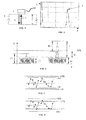
Figure 1 shows a diagram of the preventive defect detection and control process according to the present invention. -
Figure 2 schematically shows the transmission of an ultrasonic signal on an inspected part. -
Figure 3 schematically shows the backwall echo amplitude, slightly attenuated with respect to the entrance one (or backwall calibrated) once the ultrasonic signal crosses through the thickness of the part in the inspected area or point. -
Figure 4 schematically shows the overall porosity and layer porosity study ranges in the preventive detection and control process according to the present invention. -
Figure 5 shows a control chart used in the preventive detection and control process according to the present invention to analyze isolated and significant alterations. -
Figure 6 shows a control chart used in the preventive detection and control process according to the present invention to analyze slow and permanent alterations in the process. -
Figures 7 and 8 show "classic" control charts of two statistical cases representing different process capability statuses, the value quantified by means of the process capability index (Cp/Cpk or Pp/Ppk) used in the detection and control process according to the present invention. -
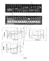
Figure 9 shows the meshing carried out in a predetermined area of a part and sampling mean, exponentially weighted moving average and standard deviation charts corresponding to each one of the cells. -
Figures 10-13 show computer screens with control charts such as those shown inFigures 5-8 corresponding to the control of "key" variables defined in "points or areas" of the part, both the variable and the zone being identified in the left portion of the screen. - Following the block diagram of
Figure 1 , thefirst step 100 of the preventive defect detection and control process in composite material parts according to the present invention is automatic data acquisition. - The control variables used in the process for detecting "potentially preventive" porosity defects (overall and in layers) are the backwall echo and the intermediate echo and the values which they acquire are:
- Backwall echo attenuation level expressed in dB or in % screen total height for overall porosity analysis.
- The value of the intermediate echo amplitude, generally expressed as % screen total height for layer porosity analysis.
- This process could likewise control any defect initially considered to be "not preventive" (delamination, foreign objects, debonding ...), monitoring the "standard" and "non-random" patterns associated to their ultrasonic echo variation in "classic" graphs, which is not the case in the corresponding improved sensitivity charts / Time weighted charts (since these defects are not usually preventable).
- Data acquisition is carried out by means of a known
machine 1 transmitting anultrasonic signal 5 on apart 3 and capturing the bouncedsignal 7 along its thickness T. - The example of
Figure 3 show the ultrasonic energy U variation of the signal along thickness T of the part, and it can be seen that thebackwall echo 9 is attenuated with respect to the entrance eco (or backwall calibrated), generally indicating the existence of an overall porosity defect in the part when critical attenuation values are reached (tolerance) unless there are significant intermediate echoes (which represent another type of defects) or identification of attenuation signals inherent to the process and not the defect. - The mentioned values are obtained automatically in each inspected part for one or several areas thereof, of constant thickness, subdivided into cells. Thickness uniformity in the analyzed cell allows filtering those "false" attenuations caused by guided bouncing of the ultrasonic signal in sloping areas or discontinuous changes on thickness.
- The analyzed areas will be those in which the corrective study has reflected the high defect generation probability (repetitive behaviors). The entire part may also be analyzed when process randomness generates defects in historically "healthy" areas.
- Each basic cell of the meshing defined by area includes the existing attenuation and intermediate echo values as the machine caliper tracks and inspects its associated area. Each inspected "point" or "basic area", usually 4 mm2, corresponds to a piece of data or measurement within the cell, including more or less values according to their basic size.
- The basic cell size for each analyzed area or zone with constant thickness will correspond to the software overflow - detection capability compromise, being standard practice to search for the largest sizes "possible" in the attempt to generate a "healthy" area in the cell when the defect evolves in said cell.
- This practice provides the standard deviation (its classic chart) with a high detection capability for the following reasons:
- The healthy and defective area combination within a single cell will cause significant alterations in the intermediate echoes or attenuation standard deviation.
- The larger the sampled population (the population of attenuations and intermediate echoes contained per basic cell), the greater the capability of the standard deviation to detect special causes for process variation.
- The standard deviation will thus provide an additional efficient statistical alarm due to any potential defect generation.
- The process herein proposed could therefore obtain those statistically representative parameters (mean, mode, median, standard deviation and whole population) of all the values obtained in the cell.
- The
data acquisition step 100 can be carried out within the part inspection process aimed at determining part compliance or non-compliance as a specific action of the process according to the present invention. - The
second step 110 of the process is the storage of the mentioned parameters of each cell in a database associated to a plurality of index data, such as the following: - Characteristic which the parameters correspond to (backwall echo or intermediate echo).
- Cell code.
- Code of the area the cell belongs to.
- Data identifying the part which the area belongs to.
- Data identifying relevant factors of the part manufacturing process (for example tools or machines used).
- Attenuation values exceeding the maximum allowed by the "gate" chosen in the machine (window Ls in
Figure 4 ) will not be included in order to avoid noise, let's take for example the approximate 18 dB under an 20% gate screen height for the backwall echo, upper tolerance limit representative of the "already" generated overall porosity defect. Should there be significant attenuation or intermediate echo values not related with the defect and "assignable" to different factors such as roughness, dirt or edge effect, said data will be acquired but will not be taken into account in the subsequent statistical analysis. - Lower tolerance limits are similarly set such that the process according to the present invention is applied to predetermined ranges. In the case shown in
Figure 4 , the overall porosity study range is the one indicated by the If interval, in which the represented attenuation value of the backwall echo Eb is found, not being possible to include values exceeding the limit set in the machine (gate Ls). The range If will be defined by the maximum screen height of the backwall echo when there is no attenuation (aspect generally related to initial machine calibration) and the chosen value of gate Ls which normally brings a compromise between defect detection and noise filtering. - For its part the layer porosity study range is the one indicated by interval I1, in which the value of intermediate echoes E1, E2... are found, discarding those "false" values (noise or grass) filtered through the window L1. The layer porosity study range I1 is defined between window L1 and 30% screen height "already" reportable as layer porosity. Values exceeding 30 % screen height are included (no upper filter) but not considered within the preventive analysis (defect has already appear)
- The
third step 120 of the process is the statistical analysis of all the stored data for a certain area of a certain part or a portion of the data (this is generally all the data of the area) chosen with a significant criterion (for example, only of the parts manufactured with the use of a certain machine in a certain period). - In a
first substep 130, the data of the controlled characteristic (backwall echo or intermediate echo) is analyzed in order to identify isolated and significant alterations of the part manufacturing process by means of, for example, a "classic" sample mean chart such as that shown inFigure 5 , in which onepoint 11 is clearly identified as being outside UCL and LCL control limits representing the natural process variability, but within the tolerance limit representative of the "already" generated defect. The identification of such alterations will give rise to the corresponding preventive action. - The existence of isolated and significant alterations in the scatter charts, such as, for example, the moving range charts shown in the lower part of
Figures 10 and11 , must similarly be identified. The scatter charts are "always" analyzed together with their corresponding individual measurements (or sample mean), a set of control charts usually known as "classic" charts. - Should no isolated alteration be detected, the process continues to the
substep 140 in which the data of the controlled characteristic (backwall echo or intermediate echo) is analyzed in order to identify possible slow and permanent alterations by means of, for example, a "special" improved sensitivity charts (moving average/exponentially weighted moving average), such as that shown inFigure 6 , in which a problem from subgroup 28 is detected, being able to speculate that the manufacturing process deficiencies began again in subgroup 24 (more or less trend behavior). The identification of such types of alterations will give rise to the corresponding preventive action. - Analysis of the graphs of
Figures 5 and 6 can identify relevant process trends, such as that shown inarea 15 ofFigure 6 (improved sensitivity graph), a non-random behavior also detected in its associated classic charts (Figure 5 ) by means of the identification of non-random patterns in area 13 (Western Electric Rules). - Also note the identification of
area 17 as a preventive action application boundary particularly after subgroup 28, the first observation out of control over the clear and decreasing trend of the improved sensitivity chart (EWMA) shown inFigure 6 . - Should no alteration be detected when having reached statistical control in both charts (classic and improved sensitivity (EWMA) graphs), the process continues to substep 150 in which the data of the controlled characteristic (backwall echo or intermediate echo) is analyzed in order to identify inspection reduction possibilities due to the low probability of the occurrence of defects. This is carried out by means of analyzing the process capability index in the analyzed meshing cells, the index being "Cp" or "Cpk" (for non-centered distributions) and calculated in normal distributions by means of the following expressions:
- Centered processes with respect to specification limits:

- Non-centered processes with respect to specification limits:

where Cpk(upper) = (UTL-X)/3σ and Cpk(lower)= (X- LTL)/3σ - A process characterized by "centered" distributions will be capable (
Figure 7 ) if its natural variability between UNL and LNL natural limits, due exclusively to random causes of the process, is lower than the variability specified by the UTL and LTL tolerance limits. - The "non-centering" of the process with respect to the tolerance interval decreases its capability value, taking this factor into account in calculating the "Cpk" index, a reference value to be analyzed in this type of distributions.
- The centering of the process will also increase the Cpk index up to a maximum value equal to the Cp index. This is why the Cp index is also known as "the process potential".
- In terms of capability index:
- Cpk > 1: Capable process
- Cpk = 1: Strictly capable process
- Cpk < 1: Non-capable process
- All those cases under control in which Cpk >> 1 will be susceptible of being inspected by sampling based on their negligible defect generation probability.
- Implementation of
step 120 of the process is carried out in a computer provided with suitable means for carrying out the mentioned statistical analyses with the data stored in the database after being acquired by the machine carrying out the ultrasonic scanning. As shown inFigure 9 , the statistical charts used in the analysis correspond to the data obtained by the ultrasonic scanning of cell 25, belonging toarea 23 inpart 21, the suitable meshing ofarea 23 object of study having been previously established with the aforementioned criteria.Figure 9 shows the preventive warning of the improved sensitivity chart in performances prior to the occurrence of the defect, that is, prior to the existence of a value outside the tolerance range in the associated classic means charts. - Results such as those shown in
Figures 10 to 13 are obtained in a preferred embodiment of the process. - Shown in the right hand portion of the screen in
Figures 10 and11 in relation to part 33 are the control charts of the "key" characteristic 31 identified in the left hand portion of the screen, and thecapability indices 35 are indicated on the lower bar. Upon analyzing their content, it can be seen that the chart ofFigure 10 represents a capable process (capability index greater than 1), whereas the chart ofFigure 11 represents a non-capable process (capability index less than 1). -
Figures 12 and13 similarly show control charts of the presence of isolated and significant alterations and slow and permanent alterations, respectively. - Any modifications comprised within the scope defined by the following claims may be introduced in the embodiments described above.
Claims (5)
- A preventive defect detection and control process in mass produced composite material parts, comprising the following steps:a) automatically obtaining, from pulse-echo ultrasonic scanning, representative parameters of backwall and intermediate echo signal results in each cell of a mesh predefined on the part or predetermined areas thereof;b) storing said parameters in a database; andc) statistically analyzing the stored parameters corresponding to certain areas of a certain part for:c1) detecting isolated and significant alterations in the part manufacturing process generating porosity defects (overall and in layers) in the analyzed area in order to be able to perform the corresponding preventive action; orc2) detecting slow and permanent alterations in the part manufacturing process generating porosity defects (overall and in layers) in the analyzed area in order to be able to perform the corresponding preventive action; orc3) detecting areas with a negligible defect generation probability in order to identify them as areas susceptible of inspection by sampling.
- A preventive defect detection and control process in composite material parts according to claim 1, characterized in that the areas subjected to control are of constant thickness.
- A preventive defect detection and control process in composite material parts according to claim 1, characterized in that the analysis of step c1) is carried out by means of classic sample mean and standard deviation charts.
- A preventive defect detection and control process in composite material parts according to claim 1, characterized in that the analysis of step c2) is carried out by means of improved sensitivity or weighted over time charts (MA/EWMA).
- A preventive defect detection and control process in composite material parts according to claim 1, characterized in that the analysis of step c3) is carried out by means of obtaining a process capability index (Cpk).
Applications Claiming Priority (1)
| Application Number | Priority Date | Filing Date | Title |
|---|---|---|---|
| PCT/ES2005/070094 WO2006136622A1 (en) | 2005-06-20 | 2005-06-20 | Method for the detection and preventive control of defects in parts that are made from composite materials |
Publications (2)
| Publication Number | Publication Date |
|---|---|
| EP1903335A1 true EP1903335A1 (en) | 2008-03-26 |
| EP1903335B1 EP1903335B1 (en) | 2017-03-08 |
Family
ID=37570130
Family Applications (1)
| Application Number | Title | Priority Date | Filing Date |
|---|---|---|---|
| EP05765625.8A Expired - Lifetime EP1903335B1 (en) | 2005-06-20 | 2005-06-20 | Process of ultrasonic detection and preventive control of defects in parts made from composite materials |
Country Status (4)
| Country | Link |
|---|---|
| US (1) | US7502712B2 (en) |
| EP (1) | EP1903335B1 (en) |
| ES (1) | ES2627494T3 (en) |
| WO (1) | WO2006136622A1 (en) |
Cited By (3)
| Publication number | Priority date | Publication date | Assignee | Title |
|---|---|---|---|---|
| CN105784852A (en) * | 2016-03-07 | 2016-07-20 | 杭州华新检测技术股份有限公司 | Concrete-structure-quality evaluating method based on ultrasonic CT |
| CN105911144A (en) * | 2016-05-17 | 2016-08-31 | 上海卫星装备研究所 | Device and method for detecting carbon fiber composite material truss bonding defects by ultrasonic phased array |
| JP2020004391A (en) * | 2018-04-24 | 2020-01-09 | エクスロン インターナショナル ゲゼルシャフト ミット ベシュレンクテル ハフツングYxlon International Gmbh | Method for obtaining at least one significant feature in a series of components of the same type and method for the classification of a component of such a series |
Families Citing this family (12)
| Publication number | Priority date | Publication date | Assignee | Title |
|---|---|---|---|---|
| JP2007188405A (en) * | 2006-01-16 | 2007-07-26 | Nec Electronics Corp | Abnormality detection system and abnormality detection method |
| US8626459B2 (en) * | 2008-09-25 | 2014-01-07 | The Regents Of The University Of California | Defect detection in objects using statistical approaches |
| EP2380015A4 (en) * | 2008-12-30 | 2016-10-26 | Sikorsky Aircraft Corp | Non-destructive inspection method with objective evaluation |
| SG187048A1 (en) * | 2010-07-12 | 2013-02-28 | Univ Ben Gurion | Analyzing ultrasonic signals using a dynamic signal processing window for an early detection of scaling in water processing equipment |
| AU2011314214A1 (en) * | 2010-09-29 | 2013-05-23 | Aerobotics, Inc. | Novel systems and methods for non-destructive inspection of airplanes |
| US9015018B2 (en) * | 2012-03-20 | 2015-04-21 | The Boeing Company | Boundary system designer for wireless aircraft networks |
| JP6061076B2 (en) * | 2012-10-29 | 2017-01-18 | 株式会社Ihi | Ultrasonic flaw detection method and apparatus |
| JP6061077B2 (en) * | 2012-10-29 | 2017-01-18 | 株式会社Ihi | Ultrasonic flaw detection method and apparatus |
| DE102015009728B4 (en) * | 2015-07-31 | 2018-10-25 | Airbus Defence and Space GmbH | Probabilistic error detection in laid fiber bands |
| CN106767580B (en) * | 2017-02-24 | 2019-10-18 | 中航复合材料有限责任公司 | The ultrasonic method of defect laying depth in a kind of determining composite layer laminated structure |
| CN114118170B (en) * | 2021-12-09 | 2025-07-15 | 杭州电力设备制造有限公司 | Distribution transformer winding defect identification method, system, device and storage medium |
| US20260120113A1 (en) * | 2024-10-24 | 2026-04-30 | Honeywell International Inc. | Corrective and preventive action configuration |
Family Cites Families (19)
| Publication number | Priority date | Publication date | Assignee | Title |
|---|---|---|---|---|
| US4674334A (en) * | 1986-05-13 | 1987-06-23 | The United States Of America As Represented By The Secretary Of The Air Force | Properties of composite laminates using leaky lamb waves |
| JP2904519B2 (en) * | 1989-12-14 | 1999-06-14 | 株式会社東芝 | Semiconductor tester |
| US5343750A (en) * | 1991-11-25 | 1994-09-06 | General Electric Company | Manual ultrasonic scanner for complex surfaces |
| WO1994001766A1 (en) * | 1992-07-14 | 1994-01-20 | Sierra Matrix, Inc. | Hands-free ultrasonic test view (hf-utv) |
| US5404754A (en) * | 1993-02-10 | 1995-04-11 | Shell Oil Company | Ultrasonic detection of high temperature hydrogen attack |
| US5445029A (en) * | 1993-11-08 | 1995-08-29 | General Electric Co. | Calibration and flaw detection method for ultrasonic inspection of acoustically noisy materials |
| JPH08110323A (en) * | 1994-10-07 | 1996-04-30 | Ishikawajima Harima Heavy Ind Co Ltd | Automatic evaluation system for ultrasonic flaw detection test results |
| US5679899A (en) * | 1995-03-06 | 1997-10-21 | Holographics Inc. | Method and apparatus for non-destructive testing of structures |
| FR2758186B1 (en) * | 1997-01-09 | 1999-02-05 | Snecma | NON-DESTRUCTIVE PROCESS FOR ESTIMATING THE AGING OF A PART MADE OF COMPOSITE MATERIAL |
| US6089095A (en) * | 1997-12-19 | 2000-07-18 | Texas Instruments Incorporated | Method and apparatus for nondestructive inspection and defect detection in packaged integrated circuits |
| WO1999036769A1 (en) * | 1998-01-16 | 1999-07-22 | Tosoh Smd, Inc. | Method of ultrasonic on-line texture characterization |
| US6128092A (en) * | 1999-07-13 | 2000-10-03 | National Research Council Of Canada | Method and system for high resolution ultrasonic imaging of small defects or anomalies. |
| JP2002207028A (en) * | 2001-01-11 | 2002-07-26 | Sumitomo Metal Ind Ltd | Defect discrimination method |
| US7024315B2 (en) * | 2001-02-08 | 2006-04-04 | University Of South Carolina | In-situ structural health monitoring, diagnostics and prognostics system utilizing thin piezoelectric sensors |
| JP2002257799A (en) * | 2001-02-28 | 2002-09-11 | Sumitomo Metal Ind Ltd | Flaw detection method and flaw detection device for solid shaft member |
| US6606909B2 (en) * | 2001-08-16 | 2003-08-19 | Lockheed Martin Corporation | Method and apparatus to conduct ultrasonic flaw detection for multi-layered structure |
| JP3961359B2 (en) * | 2002-07-18 | 2007-08-22 | 株式会社東芝 | Ultrasonic imaging device |
| US7006878B2 (en) * | 2004-02-05 | 2006-02-28 | Ford Motor Company | Computer-implemented method for analyzing a problem statement based on an integration of Six Sigma, Lean Manufacturing, and Kaizen analysis techniques |
| US7249512B2 (en) * | 2005-01-24 | 2007-07-31 | The Boeing Company | Non-destructive stringer inspection apparatus and method |
-
2005
- 2005-06-20 WO PCT/ES2005/070094 patent/WO2006136622A1/en not_active Ceased
- 2005-06-20 EP EP05765625.8A patent/EP1903335B1/en not_active Expired - Lifetime
- 2005-06-20 ES ES05765625.8T patent/ES2627494T3/en not_active Expired - Lifetime
- 2005-08-18 US US11/206,661 patent/US7502712B2/en active Active
Non-Patent Citations (1)
| Title |
|---|
| See references of WO2006136622A1 * |
Cited By (5)
| Publication number | Priority date | Publication date | Assignee | Title |
|---|---|---|---|---|
| CN105784852A (en) * | 2016-03-07 | 2016-07-20 | 杭州华新检测技术股份有限公司 | Concrete-structure-quality evaluating method based on ultrasonic CT |
| CN105784852B (en) * | 2016-03-07 | 2019-03-29 | 杭州华新检测技术股份有限公司 | A kind of concrete structure quality evaluation method based on ultrasound computed tomography |
| CN105911144A (en) * | 2016-05-17 | 2016-08-31 | 上海卫星装备研究所 | Device and method for detecting carbon fiber composite material truss bonding defects by ultrasonic phased array |
| JP2020004391A (en) * | 2018-04-24 | 2020-01-09 | エクスロン インターナショナル ゲゼルシャフト ミット ベシュレンクテル ハフツングYxlon International Gmbh | Method for obtaining at least one significant feature in a series of components of the same type and method for the classification of a component of such a series |
| US11651482B2 (en) | 2018-04-24 | 2023-05-16 | Yxlon International Gmbh | Method for obtaining at least one significant feature in a series of components of the same type and method for the classification of a component of such a series |
Also Published As
| Publication number | Publication date |
|---|---|
| US20060287836A1 (en) | 2006-12-21 |
| EP1903335B1 (en) | 2017-03-08 |
| WO2006136622A1 (en) | 2006-12-28 |
| ES2627494T3 (en) | 2017-07-28 |
| US7502712B2 (en) | 2009-03-10 |
Similar Documents
| Publication | Publication Date | Title |
|---|---|---|
| EP1903335B1 (en) | Process of ultrasonic detection and preventive control of defects in parts made from composite materials | |
| Pavlović et al. | Probability of detection as a function of multiple influencing parameters | |
| CN119559173B (en) | A PCB production line defect detection analysis method and system based on recognition model | |
| JP7314726B2 (en) | Crystal structure evaluation method and crystal structure evaluation device | |
| EP0242425A2 (en) | Method for evaluating residual fatigue life of mechanical parts | |
| CN120103225A (en) | A cable aging monitoring and early warning method and system | |
| CN119289908A (en) | Aluminum profile section thickness consistency detection method based on X-ray scanning | |
| CN120352523A (en) | Abnormal operation monitoring system for industrial circuit board | |
| CN118656586A (en) | Vulnerability analysis and toughness assessment method and system for substation structures under strong earthquakes | |
| EP3521795B1 (en) | Method and system for predicting engine performance | |
| EP2630437B1 (en) | Utilizing resonance inspection of in-service parts | |
| CN121385110B (en) | Aviation material detection method and system | |
| CN117672426A (en) | A metal fatigue life assessment and prediction method | |
| Ahmad et al. | Milling machine fault detection and identification based on a novel vitality index and temporal-residual network | |
| CN120741525B (en) | A detection and monitoring system for early warning of faults in the use of insulated slings | |
| KR101290928B1 (en) | Equipment and method for diagnosing malfunction using sound quality parameter | |
| CN118857562B (en) | Cabin cover confidentiality detection method and system based on sound wave analysis | |
| CN119619234A (en) | A non-sensing quality tracing method for the glass fiber industry | |
| CN117233347A (en) | A carbon steel spheroidization grade measurement method, system and equipment | |
| Lardner et al. | An expert-systems approach to automatically determining flaw depth within Candu pressure tubes | |
| CN119223604B (en) | A method and device for monitoring the structural health of an electric fuel pump based on stress waves | |
| CN118760937B (en) | A performance test data analysis method and system for punching and cutting device | |
| CN121298907B (en) | Bolt monitoring method and device based on electromagnetic ultrasonic and 3D phased array | |
| CN110806443A (en) | A Steel Plate Crack Assessment Method Based on Self-Organizing Statistical Model | |
| CN120427645B (en) | Quality detection method, system, device and medium for metal net |
Legal Events
| Date | Code | Title | Description |
|---|---|---|---|
| PUAI | Public reference made under article 153(3) epc to a published international application that has entered the european phase |
Free format text: ORIGINAL CODE: 0009012 |
|
| 17P | Request for examination filed |
Effective date: 20080114 |
|
| AK | Designated contracting states |
Kind code of ref document: A1 Designated state(s): AT BE BG CH CY CZ DE DK EE ES FI FR GB GR HU IE IS IT LI LT LU MC NL PL PT RO SE SI SK TR |
|
| DAX | Request for extension of the european patent (deleted) | ||
| 17Q | First examination report despatched |
Effective date: 20090717 |
|
| RAP1 | Party data changed (applicant data changed or rights of an application transferred) |
Owner name: AIRBUS OPERATIONS S.L. |
|
| REG | Reference to a national code |
Ref country code: DE Ref legal event code: R079 Ref document number: 602005051474 Country of ref document: DE Free format text: PREVIOUS MAIN CLASS: G01N0029070000 Ipc: G01N0029040000 |
|
| GRAP | Despatch of communication of intention to grant a patent |
Free format text: ORIGINAL CODE: EPIDOSNIGR1 |
|
| RIC1 | Information provided on ipc code assigned before grant |
Ipc: G01N 29/44 20060101ALI20161010BHEP Ipc: G01N 29/04 20060101AFI20161010BHEP |
|
| INTG | Intention to grant announced |
Effective date: 20161026 |
|
| GRAS | Grant fee paid |
Free format text: ORIGINAL CODE: EPIDOSNIGR3 |
|
| GRAA | (expected) grant |
Free format text: ORIGINAL CODE: 0009210 |
|
| AK | Designated contracting states |
Kind code of ref document: B1 Designated state(s): AT BE BG CH CY CZ DE DK EE ES FI FR GB GR HU IE IS IT LI LT LU MC NL PL PT RO SE SI SK TR |
|
| REG | Reference to a national code |
Ref country code: GB Ref legal event code: FG4D |
|
| RIN1 | Information on inventor provided before grant (corrected) |
Inventor name: MATEO MARTINEZ, ANTONIO MARIA |
|
| REG | Reference to a national code |
Ref country code: CH Ref legal event code: EP Ref country code: AT Ref legal event code: REF Ref document number: 873982 Country of ref document: AT Kind code of ref document: T Effective date: 20170315 |
|
| REG | Reference to a national code |
Ref country code: IE Ref legal event code: FG4D |
|
| REG | Reference to a national code |
Ref country code: DE Ref legal event code: R096 Ref document number: 602005051474 Country of ref document: DE |
|
| REG | Reference to a national code |
Ref country code: FR Ref legal event code: PLFP Year of fee payment: 13 |
|
| REG | Reference to a national code |
Ref country code: LT Ref legal event code: MG4D |
|
| REG | Reference to a national code |
Ref country code: NL Ref legal event code: MP Effective date: 20170308 |
|
| REG | Reference to a national code |
Ref country code: ES Ref legal event code: FG2A Ref document number: 2627494 Country of ref document: ES Kind code of ref document: T3 Effective date: 20170728 |
|
| PG25 | Lapsed in a contracting state [announced via postgrant information from national office to epo] |
Ref country code: LT Free format text: LAPSE BECAUSE OF FAILURE TO SUBMIT A TRANSLATION OF THE DESCRIPTION OR TO PAY THE FEE WITHIN THE PRESCRIBED TIME-LIMIT Effective date: 20170308 Ref country code: FI Free format text: LAPSE BECAUSE OF FAILURE TO SUBMIT A TRANSLATION OF THE DESCRIPTION OR TO PAY THE FEE WITHIN THE PRESCRIBED TIME-LIMIT Effective date: 20170308 Ref country code: GR Free format text: LAPSE BECAUSE OF FAILURE TO SUBMIT A TRANSLATION OF THE DESCRIPTION OR TO PAY THE FEE WITHIN THE PRESCRIBED TIME-LIMIT Effective date: 20170609 |
|
| REG | Reference to a national code |
Ref country code: AT Ref legal event code: MK05 Ref document number: 873982 Country of ref document: AT Kind code of ref document: T Effective date: 20170308 |
|
| PG25 | Lapsed in a contracting state [announced via postgrant information from national office to epo] |
Ref country code: SE Free format text: LAPSE BECAUSE OF FAILURE TO SUBMIT A TRANSLATION OF THE DESCRIPTION OR TO PAY THE FEE WITHIN THE PRESCRIBED TIME-LIMIT Effective date: 20170308 Ref country code: BG Free format text: LAPSE BECAUSE OF FAILURE TO SUBMIT A TRANSLATION OF THE DESCRIPTION OR TO PAY THE FEE WITHIN THE PRESCRIBED TIME-LIMIT Effective date: 20170608 |
|
| PG25 | Lapsed in a contracting state [announced via postgrant information from national office to epo] |
Ref country code: NL Free format text: LAPSE BECAUSE OF FAILURE TO SUBMIT A TRANSLATION OF THE DESCRIPTION OR TO PAY THE FEE WITHIN THE PRESCRIBED TIME-LIMIT Effective date: 20170308 |
|
| PG25 | Lapsed in a contracting state [announced via postgrant information from national office to epo] |
Ref country code: RO Free format text: LAPSE BECAUSE OF FAILURE TO SUBMIT A TRANSLATION OF THE DESCRIPTION OR TO PAY THE FEE WITHIN THE PRESCRIBED TIME-LIMIT Effective date: 20170308 Ref country code: EE Free format text: LAPSE BECAUSE OF FAILURE TO SUBMIT A TRANSLATION OF THE DESCRIPTION OR TO PAY THE FEE WITHIN THE PRESCRIBED TIME-LIMIT Effective date: 20170308 Ref country code: CZ Free format text: LAPSE BECAUSE OF FAILURE TO SUBMIT A TRANSLATION OF THE DESCRIPTION OR TO PAY THE FEE WITHIN THE PRESCRIBED TIME-LIMIT Effective date: 20170308 Ref country code: IT Free format text: LAPSE BECAUSE OF FAILURE TO SUBMIT A TRANSLATION OF THE DESCRIPTION OR TO PAY THE FEE WITHIN THE PRESCRIBED TIME-LIMIT Effective date: 20170308 Ref country code: AT Free format text: LAPSE BECAUSE OF FAILURE TO SUBMIT A TRANSLATION OF THE DESCRIPTION OR TO PAY THE FEE WITHIN THE PRESCRIBED TIME-LIMIT Effective date: 20170308 Ref country code: SK Free format text: LAPSE BECAUSE OF FAILURE TO SUBMIT A TRANSLATION OF THE DESCRIPTION OR TO PAY THE FEE WITHIN THE PRESCRIBED TIME-LIMIT Effective date: 20170308 |
|
| PG25 | Lapsed in a contracting state [announced via postgrant information from national office to epo] |
Ref country code: PT Free format text: LAPSE BECAUSE OF FAILURE TO SUBMIT A TRANSLATION OF THE DESCRIPTION OR TO PAY THE FEE WITHIN THE PRESCRIBED TIME-LIMIT Effective date: 20170710 Ref country code: PL Free format text: LAPSE BECAUSE OF FAILURE TO SUBMIT A TRANSLATION OF THE DESCRIPTION OR TO PAY THE FEE WITHIN THE PRESCRIBED TIME-LIMIT Effective date: 20170308 Ref country code: IS Free format text: LAPSE BECAUSE OF FAILURE TO SUBMIT A TRANSLATION OF THE DESCRIPTION OR TO PAY THE FEE WITHIN THE PRESCRIBED TIME-LIMIT Effective date: 20170708 |
|
| REG | Reference to a national code |
Ref country code: DE Ref legal event code: R097 Ref document number: 602005051474 Country of ref document: DE |
|
| PLBE | No opposition filed within time limit |
Free format text: ORIGINAL CODE: 0009261 |
|
| STAA | Information on the status of an ep patent application or granted ep patent |
Free format text: STATUS: NO OPPOSITION FILED WITHIN TIME LIMIT |
|
| PG25 | Lapsed in a contracting state [announced via postgrant information from national office to epo] |
Ref country code: DK Free format text: LAPSE BECAUSE OF FAILURE TO SUBMIT A TRANSLATION OF THE DESCRIPTION OR TO PAY THE FEE WITHIN THE PRESCRIBED TIME-LIMIT Effective date: 20170308 Ref country code: MC Free format text: LAPSE BECAUSE OF FAILURE TO SUBMIT A TRANSLATION OF THE DESCRIPTION OR TO PAY THE FEE WITHIN THE PRESCRIBED TIME-LIMIT Effective date: 20170308 |
|
| REG | Reference to a national code |
Ref country code: CH Ref legal event code: PL |
|
| 26N | No opposition filed |
Effective date: 20171211 |
|
| PG25 | Lapsed in a contracting state [announced via postgrant information from national office to epo] |
Ref country code: SI Free format text: LAPSE BECAUSE OF FAILURE TO SUBMIT A TRANSLATION OF THE DESCRIPTION OR TO PAY THE FEE WITHIN THE PRESCRIBED TIME-LIMIT Effective date: 20170308 |
|
| REG | Reference to a national code |
Ref country code: IE Ref legal event code: MM4A |
|
| PG25 | Lapsed in a contracting state [announced via postgrant information from national office to epo] |
Ref country code: CH Free format text: LAPSE BECAUSE OF NON-PAYMENT OF DUE FEES Effective date: 20170630 Ref country code: IE Free format text: LAPSE BECAUSE OF NON-PAYMENT OF DUE FEES Effective date: 20170620 Ref country code: LI Free format text: LAPSE BECAUSE OF NON-PAYMENT OF DUE FEES Effective date: 20170630 Ref country code: LU Free format text: LAPSE BECAUSE OF NON-PAYMENT OF DUE FEES Effective date: 20170620 |
|
| REG | Reference to a national code |
Ref country code: BE Ref legal event code: MM Effective date: 20170630 |
|
| REG | Reference to a national code |
Ref country code: FR Ref legal event code: PLFP Year of fee payment: 14 |
|
| PG25 | Lapsed in a contracting state [announced via postgrant information from national office to epo] |
Ref country code: BE Free format text: LAPSE BECAUSE OF NON-PAYMENT OF DUE FEES Effective date: 20170630 |
|
| PG25 | Lapsed in a contracting state [announced via postgrant information from national office to epo] |
Ref country code: HU Free format text: LAPSE BECAUSE OF FAILURE TO SUBMIT A TRANSLATION OF THE DESCRIPTION OR TO PAY THE FEE WITHIN THE PRESCRIBED TIME-LIMIT; INVALID AB INITIO Effective date: 20050620 |
|
| PGFP | Annual fee paid to national office [announced via postgrant information from national office to epo] |
Ref country code: DE Payment date: 20190619 Year of fee payment: 15 |
|
| PGFP | Annual fee paid to national office [announced via postgrant information from national office to epo] |
Ref country code: FR Payment date: 20190619 Year of fee payment: 15 |
|
| PG25 | Lapsed in a contracting state [announced via postgrant information from national office to epo] |
Ref country code: CY Free format text: LAPSE BECAUSE OF NON-PAYMENT OF DUE FEES Effective date: 20170308 |
|
| PGFP | Annual fee paid to national office [announced via postgrant information from national office to epo] |
Ref country code: GB Payment date: 20190619 Year of fee payment: 15 Ref country code: ES Payment date: 20190719 Year of fee payment: 15 |
|
| PG25 | Lapsed in a contracting state [announced via postgrant information from national office to epo] |
Ref country code: TR Free format text: LAPSE BECAUSE OF FAILURE TO SUBMIT A TRANSLATION OF THE DESCRIPTION OR TO PAY THE FEE WITHIN THE PRESCRIBED TIME-LIMIT Effective date: 20170308 |
|
| REG | Reference to a national code |
Ref country code: DE Ref legal event code: R119 Ref document number: 602005051474 Country of ref document: DE |
|
| GBPC | Gb: european patent ceased through non-payment of renewal fee |
Effective date: 20200620 |
|
| PG25 | Lapsed in a contracting state [announced via postgrant information from national office to epo] |
Ref country code: FR Free format text: LAPSE BECAUSE OF NON-PAYMENT OF DUE FEES Effective date: 20200630 Ref country code: GB Free format text: LAPSE BECAUSE OF NON-PAYMENT OF DUE FEES Effective date: 20200620 |
|
| PG25 | Lapsed in a contracting state [announced via postgrant information from national office to epo] |
Ref country code: DE Free format text: LAPSE BECAUSE OF NON-PAYMENT OF DUE FEES Effective date: 20210101 |
|
| PG25 | Lapsed in a contracting state [announced via postgrant information from national office to epo] |
Ref country code: ES Free format text: LAPSE BECAUSE OF NON-PAYMENT OF DUE FEES Effective date: 20200621 |