EP1903265B1 - Valve unit with a sliding valve plug and circuit comprising a valve of this type - Google Patents
Valve unit with a sliding valve plug and circuit comprising a valve of this type Download PDFInfo
- Publication number
- EP1903265B1 EP1903265B1 EP20070117205 EP07117205A EP1903265B1 EP 1903265 B1 EP1903265 B1 EP 1903265B1 EP 20070117205 EP20070117205 EP 20070117205 EP 07117205 A EP07117205 A EP 07117205A EP 1903265 B1 EP1903265 B1 EP 1903265B1
- Authority
- EP
- European Patent Office
- Prior art keywords
- plug
- chamber
- opening
- translation
- sliding
- Prior art date
- Legal status (The legal status is an assumption and is not a legal conclusion. Google has not performed a legal analysis and makes no representation as to the accuracy of the status listed.)
- Active
Links
Images







Classifications
-
- F—MECHANICAL ENGINEERING; LIGHTING; HEATING; WEAPONS; BLASTING
- F01—MACHINES OR ENGINES IN GENERAL; ENGINE PLANTS IN GENERAL; STEAM ENGINES
- F01P—COOLING OF MACHINES OR ENGINES IN GENERAL; COOLING OF INTERNAL-COMBUSTION ENGINES
- F01P7/00—Controlling of coolant flow
- F01P7/14—Controlling of coolant flow the coolant being liquid
-
- Y—GENERAL TAGGING OF NEW TECHNOLOGICAL DEVELOPMENTS; GENERAL TAGGING OF CROSS-SECTIONAL TECHNOLOGIES SPANNING OVER SEVERAL SECTIONS OF THE IPC; TECHNICAL SUBJECTS COVERED BY FORMER USPC CROSS-REFERENCE ART COLLECTIONS [XRACs] AND DIGESTS
- Y10—TECHNICAL SUBJECTS COVERED BY FORMER USPC
- Y10T—TECHNICAL SUBJECTS COVERED BY FORMER US CLASSIFICATION
- Y10T137/00—Fluid handling
- Y10T137/8593—Systems
- Y10T137/86493—Multi-way valve unit
- Y10T137/86501—Sequential distributor or collector type
-
- Y—GENERAL TAGGING OF NEW TECHNOLOGICAL DEVELOPMENTS; GENERAL TAGGING OF CROSS-SECTIONAL TECHNOLOGIES SPANNING OVER SEVERAL SECTIONS OF THE IPC; TECHNICAL SUBJECTS COVERED BY FORMER USPC CROSS-REFERENCE ART COLLECTIONS [XRACs] AND DIGESTS
- Y10—TECHNICAL SUBJECTS COVERED BY FORMER USPC
- Y10T—TECHNICAL SUBJECTS COVERED BY FORMER US CLASSIFICATION
- Y10T137/00—Fluid handling
- Y10T137/8593—Systems
- Y10T137/86493—Multi-way valve unit
- Y10T137/86509—Sequentially progressive opening or closing of plural ports
- Y10T137/86517—With subsequent closing of first port
Definitions
- the present invention concerns the field of controlling and checking the circulation of fluid, in particular of liquid, but also of gaseous fluid, particularly cooling liquid, in a complex circuit, for example with a plurality of partially parallel and mutually overlapping or interconnected loops, having common portions, such as the coolant circulation circuits of motor-vehicle internal combustion engines.
- the present invention relates, in the above-mentioned context, to a valve unit with a sliding throttle-chamber, regulating at least two outlets, and a cooling circuit having such a valve unit.
- a twofold problem therefore emerges, namely, that of spatially connecting the various circuit portions inside the unit (problem of overall size) and that of achieving different adjustments for the various circuit portions while respecting their hierarchy and the conditions whereby they are achieved, based on the general adjustment within the circuit as a whole.
- US-A-2 983 286 discloses a valve having a sliding plug that is movable within a valve body having a radial inlet and three radial outlet openings that are coplanar with one another.
- FR-A-623 231 discloses a three way button-operated valve having an axial inlet and radial outlet and vent ports.
- Both valves have a sliding plug with a composite structure including a plunge and a rod which are linked together with a non-driving area therebetween.
- the problem facing the present invention therefore basically consists in providing a multi-way adjustment device that requires only a simple means of actuation, for example by translation, comprising only one adjustment element and enabling connections in at least two perpendicular directions.
- the present invention relates to a valve unit with a sliding throttle-chamber, as claimed in claim 1.
- This valve unit 1 comprises a valve body 1' with an exchange or distribution chamber 3 at least partially shaped, adapted to receive a sliding plug 2 capable of being moved in a guided manner in the direction of shaped extension X of said chamber (defining an axial direction) and of which the position in translation in the chamber 3 defines the fluid communication ways between a primary or fluid inlet opening 4 and at least two secondary or fluid outlet openings 5, 6, 7 that can be selectively blocked and released by said plug.
- a secondary or outlet opening 5 opens axially into said chamber 3 and the other at least two openings 3, 6, 7 open radially therein, being offset at angles in relation to each other around the median axis and/or axis of symmetry X of said chamber, corresponding to the direction X of translation or direction of shaped extension of the chamber 3 (at least for that part of the volume of chamber 3 covered by the plug between its two extreme positions).
- the sliding plug 2 has a composite structure and consists of a first part 8 controlling the fluid communication of said, at least, one secondary or radial outlet opening 6, 7 with the chamber 3 and of a second part 9 controlling the fluid communication of the secondary or axial outlet opening 7 with the chamber 3, the two parts 8 and 9 of the plug 2 being connected together by a translation driving link with a dead or non-driving area between the two extreme translation positions of said plug 2.
- the non-driving area allows the state of release of the secondary axial opening 5 to be changed in relation to changes in the states of release of the secondary radial opening or openings 6, 7 along the length of the possible translation travel of the sliding plug 2.
- Each of the loops or circulation circuit portions connected to one of the secondary openings 5, 6, 7, will be able to have a special function or be connected to an element or module that fulfils a specific function, contributing to the general operation of the whole circulation circuit containing the valve unit 1.
- it will be necessary to choose for each one the secondary opening 5, 6, 7 to which it will be connected, as well as the way in which the two parts of the plug 8 and 9 control the flows passing through these openings and co-operate with each other with regard to the movement in translation of said plug 2.
- valve body 1' has at least three secondary or outlet openings 5, 6, 7, namely an axial secondary opening 5 and at least two radial secondary openings 6, 7, the latter being, if necessary, offset at angles and axially in relation to each other.
- the first part 8 thereof is advantageously arranged so that the inlet opening 4 is in fluid communication with the chamber 3, whatever the translation position of said plug 2.
- the valve unit 1 forms a two- or three-way valve (that is, with two or three secondary or outlet openings) and the movement in translation of the plug 2 from one extreme position to the other, starting from the extreme position corresponding to a total blocking of the two or three secondary or outlet openings 5, 6, 7 ( Figures 1A and 2A or 7A and 8A ), defines, taking into account the configuration and co-operation of the two parts 8 and 9 of the plug 2 between each other and with the chamber 3 of the valve body 1', the following sequence of different states of fluid communication:
- the non-driving area is used to defer the release of the secondary opening 5 at the end of travel of the sliding plug 2.
- the first part 8 of the plug 2 may be designed so that on the release of the secondary or axial outlet opening 5, the first secondary radial opening 6 stays released and the second secondary radial opening 7 is blocked.
- an arrangement may be made whereby only the first part 8 of the sliding throttle-chamber 2 is connected to an actuating means 10, 11 to cause its movement in translation, whereby the second part 9 of the sliding plug 2 is loaded, for example by a resilient means 12, towards a position of blocking the secondary or axial outlet opening 5 and whereby when the plug 2 moves in translation, starting from the extreme position corresponding to a blocking of the two or three secondary or outlet openings 5, 6, 7, only the first part 8 is actually moved in translation during a first driving stage corresponding to the dead or non-driving area of the connection between the two parts 8 and 9, the second part 9 not being moved in translation in order to release the secondary or axial outlet opening 5, against the above-mentioned load, except during a second stage of driving and movement in translation of the first part 8, corresponding to a positive driving engagement between the two parts 8 and 9.
- the second part 9 of the sliding plug 2 may have a thermal safety device 13, the sensitive part of which 14 is in contact with the fluid in the chamber 3 and which is capable of releasing the secondary or axial outlet opening 5, if necessary against a normal load when the blocking element 15 of the second part 9 closes and possibly also by moving the latter.
- Dispensing with the safety function (default state or position) of the actuator 11 allows simple and inexpensive actuators to be used.
- the first part 8 of the sliding plug 2 basically has the form of a hollow cylindrical sleeve, the constituent wall of which 8' has, on the one hand, an external shape adapted to slide at least partially guided inside the chamber 3 of the valve body 1' between two extreme near and far positions from the secondary or axial outlet opening 5 and, on the other hand, cut-outs 16, 16' which can be brought opposite one of the two secondary or radial outlet openings 6 and 7 during the movement in translation of the first part 8 of the sliding plug 2 between the two extreme positions, successively defining a plurality of states of fluid communication with the exchange chamber 3.
- cut-outs 16 and 16' depend on the desired sequence of the states of fluid communication.
- said cut-outs 16, 16' may have either a contour that corresponds exactly to the contour of the opening 6, 7 to which they are respectively associated (totally releasing the corresponding opening in one precise position of the first part 8), or a smaller contour than that of the associated opening (resulting in at most a partial release of the corresponding opening), or even a contour with a rectangular shape elongate in the direction of translation X or of the axis of symmetry of the sleeve 8', having the same or shorter length than the diameter of the associated opening, or having a variable width (controlled and preset variation of the section of released passage of the associated opening depending on the degree of movement of the first part 8).
- the cut-out 16" of the sleeve 8' designed to face the primary or inlet opening 4 will be of sufficient width and length for this opening 4 to be permanently released for the most part. It will therefore extend along most of the length of the sleeve 8' and will be at least the same width as the transverse dimension of the opening 4.
- the second part 9 of the sliding plug 2 basically comprises a blocking element 15 either indirectly or directly mounted on an elongate driving element 17 connected operationally, by a translation drive link with a dead or non-driving area, to the first part 8 of said plug 2, a resilient means 12 pushing the blocking element 15 in a closed position of the secondary or axial outlet opening 5, in the direction of translation X of said sliding plug 2 and said elongate drive element 17 extending into the first part 8 of the plug 2 in the form of a hollow sleeve.
- the hollow cylindrical sleeve 8' forming the body of the first part 8 of the plug 2 may, for example, have a cross-piece 18 connected to a control rod 10 which can be moved in translation by an actuator 11 and the elongate drive element 17 of the second part 9 of the plug 2, having a hollow cylindrical structure for example, may have a longitudinally extended through-slot that receives, with a possibility of limited free sliding, the above-mentioned cross-piece 18, said limited free sliding travel defining the dead or non-driving area of the drive link existing between the first and second parts 8, 9 of the plug 2.
- the through-slot 19 is in the form of two opposing cut-outs in the form of slots made in the wall of said hollow body.
- the resilient means 12 pushing the blocking element 15 of the second part 9 of the plug 2 into a closed position consists of a compression spring mounted on a support ring 20 located opposite the secondary or axial outlet opening 5 and held by a support structure 21, for example in the form of arms.
- these arms (21) can rest on the wall 3' of the chamber 3 opposite the secondary or axial outlet opening 5, the supporting ring 20 and its supporting structure 21 extending between the elongate drive element 17 and the wall 8' of the hollow sleeve forming the body of the first part 8 of the sliding plug 2.
- said ring 20 and said arms 21 can together form a stirrup resting on the valve body 1' in the region of the opening 5 and extending around the second part 9 of the sliding plug 2.
- the arms 21 of the stirrup thus rest on the internal surface portions 23 of the wall of the valve body 1' located around the axial opening 5 and a second compression spring 24 is mounted so as to rest under stress, for the one part, on the ring 20 or the arms 21 of the stirrup and, for the other part, on the cross-piece 18 of the body 8' of the first part of the throttle-chamber 2, the axial thrust provided by said second spring 24 through the stirrup being greater than the opposing axial thrust delivered by the first spring 12, so that the ends of the arms 21 of said stirrup rest against the internal surface portions 23, whatever the axial translation position of the body 8' of the first part 8 of the plug 2 in the valve body 1
- this second compression spring 24 by preloading, can limit the force to be provided by the actuator 11 to move the plug 2 into its position shown in Figures 1D , 2D , 7D and 8D (release of axial opening 5), so that an actuator 11 which provides a substantially unidirectional force can be chosen.
- the valve body 1' may have on its internal face, in the region of the surface portions 23, protuberant formations 25 forming with said surface portions 23 reception points for the ends of the arms 21 of the stirrup, resembling a bayonet fitting, and the cross-piece 18 of the body 8' of the first part 8 of the plug 2 may consist of two opposing projections 26 formed on the internal face of the wall of said first part 8 to which is affixed a nut 27 fitted with fastening arms 27', said nut 27 co-operating with the control rod 10 produced in the form of a threaded screw, and the first part 8 of the plug 2 being guided whilst sliding into the valve body 1' and locked in rotation around the axis of sliding X, for example by co-operation of longitudinal ribs 8" of the first part 8 with the internal grooves of the valve body 1' ( Figures 7 to 9 ).
- the latter may have, as is shown in Figures 1 to 6 , an exchange chamber 3 which is open on the side opposite the wall supporting the secondary or axial outlet opening 5, said open side being blocked tightly by the casing 11' of an actuator 11 allowing the movement in translation of the sliding plug 2 by means of a control rod 10.
- said chamber 3 advantageously has a lateral recess 3" forming a radial volume extension where the primary or inlet opening 4 emerges into said chamber 3.
- the thermal safety device 13 preferably consists of a wax cartridge module 14, bearing the blocking element 15 of the second part 9 of the sliding throttle-chamber 2 and fitted in a front portion 17' of the elongate drive element 17, said module 13 being designed to move the blocking element 15 out of its closed position, against the load exerted on said element.
- the module 14 is in contact with the liquid or gaseous fluid inside chamber 3 or circulating through the latter and is triggered when an upper threshold temperature is exceeded, releasing the opening 5 by moving the element 15 against the load of spring 12.
- the secondary or outlet openings 5, 6 and 7 may be externally extended by respective end-pieces 5', 6' and 7' and the valve body 1' may have connecting points 22 or 29" on its external face around the primary or inlet opening 4.
- the end-piece 5' may have a bearing 5" to hold and guide a part of the blocking element 15 or the thermal safety module 13.
- the valve body 1' may be formed of one or a plurality of parts, of a thermoplastic or other material, by injection moulding of one piece or by joining a plurality of parts which have been separately injection-moulded.
- the valve body 1' comprises two constituent parts joined together tightly, namely, a first main part 28 having a hollow substantially cylindrical overall structure, which has the inlet opening 4 and the secondary or radial outlet opening or openings 6, 7 and in which the plug 2 is slidably mounted, and a second part 28' in the form of a lid or cover which closes one of the end openings of the first cylindrical constituent part 28 and which incorporates the secondary or axial outlet opening 5, as well as an end-piece 5' extending said opening 5 towards the exterior, the other end opening of the first constituent part 28 being blocked, at least partially, by the casing 11' of an actuator 11, allowing the movement in translation of the sliding plug 2.
- the two parts 28 and 28' which are tightly joined, for example by vibration fusing, thus forming the chamber 3.
- the first main part 28 of the valve body 1' has a composite composition and comprises an internal cylindrical piece 29 forming a sliding guiding element for the first cylindrical part 8 of the plug 2 and an external piece 29' forming the structural body and having exterior joining or connecting points 29", 29''' in the region of the inlet opening 4, for the secondary radial opening or openings 5, 6, 7 and for the end opening closed by the second part 28' in the form of a lid or cover, the external piece 29' preferably being over-moulded onto said internal piece 29 and said two pieces 29 and 29' having coincident cut-outs defining the aforementioned inlet and radial openings.
- This composite composition of the valve body 1' results in an internal chamber 3 with very good cylindricity, enabling precise, smooth guidance without jamming, possibly aided by an appropriate choice of materials which have a low coefficient of friction and are resistant to wear (for example, PPS - polyphenylsiloxane).
- the over-moulding material forming the external body 29' preferably consists of a material of high mechanical strength which is inexpensive and easily injected (for example, polyamide which has possibly been reinforced).
- the end-pieces 6', 7' may possibly, as shown in Figures 7, 8 , 9 , 10 , 11 and 12 , have connection interface portions 6", 7" the conformation of which allows a tight joint at additional points 29'" formed in the region of the radial openings 6, 7, for example by vibration fusing or adhesion.
- the end-pieces 6', 7' may be separate ( Fig. 7, 8 , 12 ) or integral with a common connection interface portion 6", 7" ( Fig. 9 , 10 , 11 ).
- connection interface portion 7" of the end-piece 7' may if necessary be incorporated into the connection interface portion 7" of the end-piece 7', thus allowing the formation of a circulation unit in the form of a complex piece 36 affixed to the valve body 1' and either incorporating or not incorporating the end-piece 6' (cf. Fig. 9 and 12 ).
- the first part 8 of the sliding plug 2 consists of a composite piece 30, 32.
- This piece has a hollow cylindrical support structure 30 which can slide inside the chamber 3 of the valve body 1' and which basically consists of a perforated peripheral wall 8', of which a first aperture or a first series of apertures in the form of a cut-out or cut-outs 16" forms a travel opening and is to be positioned opposite the inlet opening 4 so as to allow communication between the latter and the chamber 3, whatever the translation position of the first part 8 of the plug 2, and of which at least one other aperture 31 receives an insert 32 in the form of a curved plate with a cut-out 16, 16' to be brought opposite an outlet or secondary radial opening 6, 7 during the sliding travel of the first part 8 of the plug 2 into the chamber 3 of the valve body 1'.
- the or each curved plate forming an insert 32 is fitted movably into the perforated cylindrical support structure 30 by being loaded radially towards the exterior by the action of a resilient load, provided, for example by one or more compression springs 33, the said plate 32 being guided radially and held in the support structure 30 by corresponding co-operating means of said plate 32 and said support 30, so as to allow a limited protuberant extension of the exterior surface of said plate 32 beyond the cylindrical surface defined by the exterior surface of the wall 8' of said support structure 30.
- a resilient load provided, for example by one or more compression springs 33
- the co-operating guidance and holding means for each plate 32 consist, for the one part, of a pair of shaped vanes 34 formed on the internal surface of said plate 32 and the free sides 34' of which are shaped into hooks and, for the other part, of internal projections 35 in the form of opposing fins of the support structure 30, the maximum extension position towards the exterior of the plate 32 being defined by the abutment of the hooks 34' of the vanes 34 of said plate 32 on said projections 35 and the radial movement of said plate 32 being guided by sliding support of said projections 35 on said vanes 34, and, if necessary, by lateral contact between the sides 32' of said plate 32 and the sides of the corresponding aperture 31 made in the wall 8' forming the support structure 30.
- the invention also relates to a cooling circuit for an internal combustion engine, characterised in that it comprises a valve unit 1 as described above and illustrated in the accompanying drawings, the primary or inlet opening 4 of which is directly connected to the outlet or inlet of the cooling circuit portions integral with the engine block.
- the secondary or axial outlet opening 5 is fluidly connected to a radiator, the first secondary or radial outlet opening 6 is connected fluidly to a unit heater and the second secondary or radial outlet opening 7 is connected fluidly to a by-pass circuit.
- the invention also relates to a process for manufacturing a valve unit as previously described, in particular with reference to Figures 7 to 11 .
- This process basically consists in providing, in the form of a pre-assembled sub-unit, a second part 9 of plug 2 comprising in particular a blocking element 15 mounted on an elongate driving body, a resilient means 12 and a stirrup having a support ring 20 and arms 21, as well as, if necessary, a second compression spring 24, in also providing the first and second parts 28 and 28' of the valve body 1', an actuating means 11 with a control rod 10 and a first part 8 of plug 2, in fitting the first part 8 of the throttle-chamber into the first part 28 of the valve body 1' and the actuating means 11 thereon, in operationally joining the first part 8 of the plug 2 to the control rod 10, in positioning the sub-unit forming the second part 9 of plug 2 in the first part 8 and in joining the second part 28' of the valve body 1' to the first part 28 so as to tightly close the chamber 3, whilst achieving the locked positioning of the
- the process may also consist in connecting at least some end-pieces 6', 7' extending the outlet or secondary radial opening or openings 6, 7 over the corresponding joining points 29", 29'" formed on the first part 28 of the valve body1', before or after fitting the other components.
Landscapes
- Engineering & Computer Science (AREA)
- Chemical & Material Sciences (AREA)
- Combustion & Propulsion (AREA)
- Mechanical Engineering (AREA)
- General Engineering & Computer Science (AREA)
- Multiple-Way Valves (AREA)
- Temperature-Responsive Valves (AREA)
- Lift Valve (AREA)
- Pens And Brushes (AREA)
- Slot Machines And Peripheral Devices (AREA)
- Lock And Its Accessories (AREA)
- Magnetically Actuated Valves (AREA)
Abstract
Description
- The present invention concerns the field of controlling and checking the circulation of fluid, in particular of liquid, but also of gaseous fluid, particularly cooling liquid, in a complex circuit, for example with a plurality of partially parallel and mutually overlapping or interconnected loops, having common portions, such as the coolant circulation circuits of motor-vehicle internal combustion engines.
- The present invention relates, in the above-mentioned context, to a valve unit with a sliding throttle-chamber, regulating at least two outlets, and a cooling circuit having such a valve unit.
- In view of the need to reduce manufacturing costs, space occupied and total weight, which is particularly pressing in the field of motorcar manufacture, there is strong demand to reduce the number of fluid-circulation adjustment and control elements in complex circuits and if possible to incorporate all the adjustment and control functions in one operational and structural assembly, operated by one actuator, thus producing one adjustment unit for a plurality of circuit portions of the same general circuit.
- Another possible way of reducing costs consists in fitting actuators that are cheap to manufacture and therefore uncomplicated and of a simple structure.
- A twofold problem therefore emerges, namely, that of spatially connecting the various circuit portions inside the unit (problem of overall size) and that of achieving different adjustments for the various circuit portions while respecting their hierarchy and the conditions whereby they are achieved, based on the general adjustment within the circuit as a whole.
- The above-mentioned problems arise principally with regard to the adjustment, by means of a structural device or single module, of the circulation of coolant within a circuit comprising a main portion and at least two, preferably three, secondary portions, namely, for example, not only the circuit running through the engine block, but also a loop passing through a radiator, a loop passing through a unit heater, and possibly a by-pass loop.
-
US-A-2 983 286 discloses a valve having a sliding plug that is movable within a valve body having a radial inlet and three radial outlet openings that are coplanar with one another. -
FR-A-623 231 - Both valves have a sliding plug with a composite structure including a plunge and a rod which are linked together with a non-driving area therebetween.
- The problem facing the present invention therefore basically consists in providing a multi-way adjustment device that requires only a simple means of actuation, for example by translation, comprising only one adjustment element and enabling connections in at least two perpendicular directions.
- For this purpose, the present invention relates to a valve unit with a sliding throttle-chamber, as claimed in
claim 1. - A better understanding of the invention will be facilitated by the following description which relates to a preferred embodiment, given by way of a non-limiting example and explained with reference to the appended schematic drawings, in which:
-
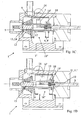
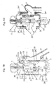
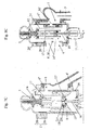
Figures 1A, 1B ,1C and 1D are cross-sections along a plane containing the axis of translation of the sliding plug, of a valve unit according to the invention, illustrating four different translation positions of said plug ; -
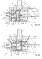
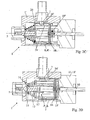
Figures 2A, 2B ,2C and 2D are similar views to those shown inFigures 1A, 1B ,1C and 1D respectively, along another plane containing the axis of translation of the sliding plug; -
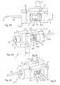
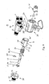
Figure 3 is an exploded perspective view of the valve unit shown inFigures 1 and2 ; -
Figure 4 is a perspective view in the assembled state of the valve shown inFigure 3 ; -
Figure 5 is a cutaway view through the body of the valve of the valve unit shown inFigure 4 , and -
Figures 6A, 6B and 6C are views from below (Figure 6A ) and in perspective respectively showing the primary or inlet opening, the sliding plug being substantially in a position similar to that shown inFigures 1D and2D . -
Figures 7A ,7B ,7C and7D are cross-sections along a plane containing the axis of translation of the sliding plug of a valve unit according to a variation of the invention, illustrating four different translation positions of said plug ; -
Figures 8A ,8B ,8C and8D are cross-sections similar to those shown inFigures 7A ,7B ,7C and7D respectively (same positions of the plug), along another plane containing the axis of translation of the sliding plug; -
Figure 9 is an exploded perspective view of a valve unit as shown inFigures 7 and 8 , with a complex piece incorporating the end-pieces of the first and second radial openings; -
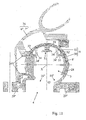
Figures 10A and 10B are offset cross-sections along a plane perpendicular to the axis of translation of the plug, illustrating in particular a possible composite composition of the first constituent part of the valve body forming part of the valve unit inFigures 7 to 9 ; -
Figure 11 is a cross-section identical to those shown inFigures 10A and 10B , to a different scale, showing a first part of plug with a composite structure forming part of the valve unit as shown inFigures 7 to 10 , and -
Figures 12A, 12B, 12C and 12D illustrate four consecutive stages of manufacture of a valve unit as shown inFigures 7 to 11 . - The accompanying drawings in
Figures 1 to 12 show amulti-way valve unit 1 with asliding plug 2. - This
valve unit 1 comprises avalve body 1' with an exchange ordistribution chamber 3 at least partially shaped, adapted to receive asliding plug 2 capable of being moved in a guided manner in the direction of shaped extension X of said chamber (defining an axial direction) and of which the position in translation in thechamber 3 defines the fluid communication ways between a primary or fluid inlet opening 4 and at least two secondary orfluid outlet openings - A secondary or outlet opening 5 opens axially into
said chamber 3 and the other at least twoopenings chamber 3 covered by the plug between its two extreme positions). - According to the invention, the
sliding plug 2 has a composite structure and consists of afirst part 8 controlling the fluid communication of said, at least, one secondary or radial outlet opening 6, 7 with thechamber 3 and of asecond part 9 controlling the fluid communication of the secondary or axial outlet opening 7 with thechamber 3, the twoparts plug 2 being connected together by a translation driving link with a dead or non-driving area between the two extreme translation positions of saidplug 2. - Owing to the above-mentioned arrangements, it is possible, with one operational element moved by a simple movement in translation, to control the circulation of liquid or gaseous fluid through at least two
openings valve body 1', notably with asecondary opening 5 facing the direction of translation X (positioned axially) and the other secondary opening oropenings - Moreover, the non-driving area allows the state of release of the secondary
axial opening 5 to be changed in relation to changes in the states of release of the secondary radial opening oropenings sliding plug 2. - Each of the loops or circulation circuit portions connected to one of the
secondary openings valve unit 1. Thus, when taking into account the role to be played by each of the loops or circuit portions, as well as their spatial arrangement, it will be necessary to choose for each one thesecondary opening plug plug 2. - Although the present invention can apply fully in the case of two-way valves (that is, with two outlet or
secondary openings 5 and 6), it can apply even more advantageously when producing valves with at least three ways, and in this latter case, thevalve body 1' has at least three secondary oroutlet openings secondary opening 5 and at least two radialsecondary openings - Furthermore, in order to ensure a permanent supply to the
chamber 3, whatever the state ofvalve 1, thefirst part 8 thereof is advantageously arranged so that the inlet opening 4 is in fluid communication with thechamber 3, whatever the translation position of saidplug 2. - According to a preferred embodiment of the invention, shown in
Figures 1 and2 , and inFigures 7 and 8 , thevalve unit 1 forms a two- or three-way valve (that is, with two or three secondary or outlet openings) and the movement in translation of theplug 2 from one extreme position to the other, starting from the extreme position corresponding to a total blocking of the two or three secondary oroutlet openings Figures 1A and2A or7A and 8A ), defines, taking into account the configuration and co-operation of the twoparts plug 2 between each other and with thechamber 3 of thevalve body 1', the following sequence of different states of fluid communication: - release of the or a first secondary or radial outlet opening 6 (
Figures 1B and2B or7B and 8B ); - release, if necessary, of the second secondary or radial outlet opening 7, the first
radial opening 6 remaining free (Figures 1C and2C or7C and 8C ); - release of the secondary or axial outlet opening 5, if necessary, while keeping the radial opening or at least one of the two
radial openings Figures 1D and2D or7E and 8D ). - In this preferred variation, the non-driving area is used to defer the release of the
secondary opening 5 at the end of travel of thesliding plug 2. According to another characteristic of the invention, also shown inFigures 1 and2 , as well as inFigures 7 and 8 , in the case of a three-way valve, thefirst part 8 of theplug 2 may be designed so that on the release of the secondary or axial outlet opening 5, the first secondaryradial opening 6 stays released and the second secondaryradial opening 7 is blocked. - According to a possible embodiment of the invention that enables, for example, an operating sequence as previously described based on the movement of the
plug 2, an arrangement may be made whereby only thefirst part 8 of the sliding throttle-chamber 2 is connected to an actuating means 10, 11 to cause its movement in translation, whereby thesecond part 9 of the slidingplug 2 is loaded, for example by aresilient means 12, towards a position of blocking the secondary or axial outlet opening 5 and whereby when theplug 2 moves in translation, starting from the extreme position corresponding to a blocking of the two or three secondary oroutlet openings first part 8 is actually moved in translation during a first driving stage corresponding to the dead or non-driving area of the connection between the twoparts second part 9 not being moved in translation in order to release the secondary or axial outlet opening 5, against the above-mentioned load, except during a second stage of driving and movement in translation of thefirst part 8, corresponding to a positive driving engagement between the twoparts - Furthermore, when the loop or circuit portion connected to the secondary
axial opening 5 is a back-up or positive safety circuit for the entire circuit incorporating the valve unit, thesecond part 9 of thesliding plug 2 may have athermal safety device 13, the sensitive part of which 14 is in contact with the fluid in thechamber 3 and which is capable of releasing the secondary or axial outlet opening 5, if necessary against a normal load when the blockingelement 15 of thesecond part 9 closes and possibly also by moving the latter. - Dispensing with the safety function (default state or position) of the
actuator 11 allows simple and inexpensive actuators to be used. - According to a practical embodiment of the invention, having a three-way valve structure (that is with three outlet or
secondary openings first part 8 of thesliding plug 2 basically has the form of a hollow cylindrical sleeve, the constituent wall of which 8' has, on the one hand, an external shape adapted to slide at least partially guided inside thechamber 3 of thevalve body 1' between two extreme near and far positions from the secondary or axial outlet opening 5 and, on the other hand, cut-outs 16, 16' which can be brought opposite one of the two secondary orradial outlet openings first part 8 of thesliding plug 2 between the two extreme positions, successively defining a plurality of states of fluid communication with theexchange chamber 3. - The shape, dimensions and arrangement of the cut-
outs 16 and 16' depend on the desired sequence of the states of fluid communication. - Thus, said cut-
outs 16, 16' may have either a contour that corresponds exactly to the contour of theopening - The cut-out 16" of the sleeve 8' designed to face the primary or inlet
opening 4 will be of sufficient width and length for thisopening 4 to be permanently released for the most part. It will therefore extend along most of the length of the sleeve 8' and will be at least the same width as the transverse dimension of theopening 4. - According to another characteristic of the above-described practical variation and as is also shown in the accompanying drawings, the
second part 9 of thesliding plug 2 basically comprises a blockingelement 15 either indirectly or directly mounted on anelongate driving element 17 connected operationally, by a translation drive link with a dead or non-driving area, to thefirst part 8 of saidplug 2, aresilient means 12 pushing the blockingelement 15 in a closed position of the secondary or axial outlet opening 5, in the direction of translation X of said slidingplug 2 and saidelongate drive element 17 extending into thefirst part 8 of theplug 2 in the form of a hollow sleeve. - In order to create the drive link between the first and
second parts sliding plug 2 in a simple manner, the hollow cylindrical sleeve 8' forming the body of thefirst part 8 of theplug 2 may, for example, have across-piece 18 connected to acontrol rod 10 which can be moved in translation by anactuator 11 and theelongate drive element 17 of thesecond part 9 of theplug 2, having a hollow cylindrical structure for example, may have a longitudinally extended through-slot that receives, with a possibility of limited free sliding, the above-mentionedcross-piece 18, said limited free sliding travel defining the dead or non-driving area of the drive link existing between the first andsecond parts plug 2. - If the
elongate element 17 is in the form of a hollow body, in particular with a cylindrical structure, the through-slot 19 is in the form of two opposing cut-outs in the form of slots made in the wall of said hollow body. - Moreover, so that the
cross-piece 18, either formed or not formed in one piece with the wall of the sleeve 8', can be fitted easily into saidslot 19, the longitudinal cut-outs forming the latter by co-operation may emerge at the trailing end of the elongate element 17 (the end opposite portion 17'), theslot 19 being delimited in this direction by a clip 19' or a similar inserted piece forming a stop for thecross-piece 18. - Advantageously, the resilient means 12 pushing the blocking
element 15 of thesecond part 9 of theplug 2 into a closed position consists of a compression spring mounted on asupport ring 20 located opposite the secondary or axial outlet opening 5 and held by asupport structure 21, for example in the form of arms. - According to a first constructional variation, shown in
Figures 1 to 6 , these arms (21) can rest on the wall 3' of thechamber 3 opposite the secondary or axial outlet opening 5, the supportingring 20 and its supportingstructure 21 extending between theelongate drive element 17 and the wall 8' of the hollow sleeve forming the body of thefirst part 8 of thesliding plug 2. - According to a second constructional variation, shown in
Figures 7 to 12 , saidring 20 and saidarms 21 can together form a stirrup resting on thevalve body 1' in the region of theopening 5 and extending around thesecond part 9 of thesliding plug 2. - As is shown in
Figures 7 and9 in particular, thearms 21 of the stirrup thus rest on theinternal surface portions 23 of the wall of thevalve body 1' located around theaxial opening 5 and asecond compression spring 24 is mounted so as to rest under stress, for the one part, on thering 20 or thearms 21 of the stirrup and, for the other part, on thecross-piece 18 of the body 8' of the first part of the throttle-chamber 2, the axial thrust provided by saidsecond spring 24 through the stirrup being greater than the opposing axial thrust delivered by thefirst spring 12, so that the ends of thearms 21 of said stirrup rest against theinternal surface portions 23, whatever the axial translation position of the body 8' of thefirst part 8 of theplug 2 in thevalve body 1 - Moreover, this
second compression spring 24, by preloading, can limit the force to be provided by theactuator 11 to move theplug 2 into its position shown inFigures 1D ,2D ,7D and 8D (release of axial opening 5), so that anactuator 11 which provides a substantially unidirectional force can be chosen. - According to another characteristic of the invention, the
valve body 1' may have on its internal face, in the region of thesurface portions 23,protuberant formations 25 forming with saidsurface portions 23 reception points for the ends of thearms 21 of the stirrup, resembling a bayonet fitting, and thecross-piece 18 of the body 8' of thefirst part 8 of theplug 2 may consist of twoopposing projections 26 formed on the internal face of the wall of saidfirst part 8 to which is affixed anut 27 fitted with fastening arms 27', saidnut 27 co-operating with thecontrol rod 10 produced in the form of a threaded screw, and thefirst part 8 of theplug 2 being guided whilst sliding into thevalve body 1' and locked in rotation around the axis of sliding X, for example by co-operation oflongitudinal ribs 8" of thefirst part 8 with the internal grooves of thevalve body 1' (Figures 7 to 9 ). - To make it easier to create the
valve body 1' and fit thesliding plug 2 into theinternal exchange chamber 3 formed in said body, the latter may have, as is shown inFigures 1 to 6 , anexchange chamber 3 which is open on the side opposite the wall supporting the secondary or axial outlet opening 5, said open side being blocked tightly by the casing 11' of anactuator 11 allowing the movement in translation of thesliding plug 2 by means of acontrol rod 10. - Furthermore, said
chamber 3 advantageously has alateral recess 3" forming a radial volume extension where the primary orinlet opening 4 emerges intosaid chamber 3. - According to another characteristic of the invention, the
thermal safety device 13 preferably consists of awax cartridge module 14, bearing the blockingelement 15 of thesecond part 9 of the sliding throttle-chamber 2 and fitted in a front portion 17' of theelongate drive element 17, saidmodule 13 being designed to move the blockingelement 15 out of its closed position, against the load exerted on said element. - The
module 14 is in contact with the liquid or gaseous fluid insidechamber 3 or circulating through the latter and is triggered when an upper threshold temperature is exceeded, releasing theopening 5 by moving theelement 15 against the load ofspring 12. - Regarding notably an application of the invention in the context of engine cooling, the secondary or
outlet openings valve body 1' may have connectingpoints inlet opening 4. - The end-piece 5' may have a bearing 5" to hold and guide a part of the blocking
element 15 or thethermal safety module 13. - The
valve body 1' may be formed of one or a plurality of parts, of a thermoplastic or other material, by injection moulding of one piece or by joining a plurality of parts which have been separately injection-moulded. - According to a variation of the invention, shown in particular in
Figures 7, 8 ,9 and12 , thevalve body 1' comprises two constituent parts joined together tightly, namely, a firstmain part 28 having a hollow substantially cylindrical overall structure, which has theinlet opening 4 and the secondary or radial outlet opening oropenings plug 2 is slidably mounted, and asecond part 28' in the form of a lid or cover which closes one of the end openings of the first cylindricalconstituent part 28 and which incorporates the secondary oraxial outlet opening 5, as well as an end-piece 5' extending saidopening 5 towards the exterior, the other end opening of the firstconstituent part 28 being blocked, at least partially, by the casing 11' of anactuator 11, allowing the movement in translation of the slidingplug 2. - The two
parts chamber 3. - Advantageously, the first
main part 28 of thevalve body 1' has a composite composition and comprises an internalcylindrical piece 29 forming a sliding guiding element for the firstcylindrical part 8 of theplug 2 and an external piece 29' forming the structural body and having exterior joining or connectingpoints 29", 29''' in the region of theinlet opening 4, for the secondary radial opening oropenings second part 28' in the form of a lid or cover, the external piece 29' preferably being over-moulded onto saidinternal piece 29 and said twopieces 29 and 29' having coincident cut-outs defining the aforementioned inlet and radial openings. - This composite composition of the
valve body 1' results in aninternal chamber 3 with very good cylindricity, enabling precise, smooth guidance without jamming, possibly aided by an appropriate choice of materials which have a low coefficient of friction and are resistant to wear (for example, PPS - polyphenylsiloxane). The over-moulding material forming the external body 29' preferably consists of a material of high mechanical strength which is inexpensive and easily injected (for example, polyamide which has possibly been reinforced). - The end-pieces 6', 7' may possibly, as shown in
Figures 7, 8 ,9 ,10 ,11 and12 , haveconnection interface portions 6", 7" the conformation of which allows a tight joint at additional points 29'" formed in the region of theradial openings - The end-pieces 6', 7' may be separate (
Fig. 7, 8 ,12 ) or integral with a commonconnection interface portion 6", 7" (Fig. 9 ,10 ,11 ). - Moreover, the end-piece connections of other circuit portions may if necessary be incorporated into the
connection interface portion 7" of the end-piece 7', thus allowing the formation of a circulation unit in the form of acomplex piece 36 affixed to thevalve body 1' and either incorporating or not incorporating the end-piece 6' (cf.Fig. 9 and12 ). - According to another characteristic of the invention, shown in particular in
Figures 9 and11 , thefirst part 8 of the slidingplug 2 consists of acomposite piece cylindrical support structure 30 which can slide inside thechamber 3 of thevalve body 1' and which basically consists of a perforated peripheral wall 8', of which a first aperture or a first series of apertures in the form of a cut-out or cut-outs 16" forms a travel opening and is to be positioned opposite theinlet opening 4 so as to allow communication between the latter and thechamber 3, whatever the translation position of thefirst part 8 of theplug 2, and of which at least oneother aperture 31 receives aninsert 32 in the form of a curved plate with a cut-out 16, 16' to be brought opposite an outlet or secondaryradial opening first part 8 of theplug 2 into thechamber 3 of thevalve body 1'. - Advantageously, the or each curved plate forming an
insert 32 is fitted movably into the perforatedcylindrical support structure 30 by being loaded radially towards the exterior by the action of a resilient load, provided, for example by one or more compression springs 33, the saidplate 32 being guided radially and held in thesupport structure 30 by corresponding co-operating means of saidplate 32 and saidsupport 30, so as to allow a limited protuberant extension of the exterior surface of saidplate 32 beyond the cylindrical surface defined by the exterior surface of the wall 8' of saidsupport structure 30. - This arrangement results in an improved seal in the region of the aforementioned cut-out 16 and/or 16' by permanent intimate contact between the corresponding plate and the internal face of the
chamber 3. - According to a possible practical embodiment, shown in
Figure 11 , the co-operating guidance and holding means for eachplate 32 consist, for the one part, of a pair of shapedvanes 34 formed on the internal surface of saidplate 32 and the free sides 34' of which are shaped into hooks and, for the other part, ofinternal projections 35 in the form of opposing fins of thesupport structure 30, the maximum extension position towards the exterior of theplate 32 being defined by the abutment of the hooks 34' of thevanes 34 of saidplate 32 on saidprojections 35 and the radial movement of saidplate 32 being guided by sliding support of saidprojections 35 on saidvanes 34, and, if necessary, by lateral contact between the sides 32' of saidplate 32 and the sides of the correspondingaperture 31 made in the wall 8' forming thesupport structure 30. - The invention also relates to a cooling circuit for an internal combustion engine, characterised in that it comprises a
valve unit 1 as described above and illustrated in the accompanying drawings, the primary or inlet opening 4 of which is directly connected to the outlet or inlet of the cooling circuit portions integral with the engine block. - Advantageously, the secondary or
axial outlet opening 5 is fluidly connected to a radiator, the first secondary orradial outlet opening 6 is connected fluidly to a unit heater and the second secondary orradial outlet opening 7 is connected fluidly to a by-pass circuit. - Finally, the invention also relates to a process for manufacturing a valve unit as previously described, in particular with reference to
Figures 7 to 11 . - This process, four main stages of which are shown in
Figures 12A, 12B, 12C and 12D , basically consists in providing, in the form of a pre-assembled sub-unit, asecond part 9 ofplug 2 comprising in particular a blockingelement 15 mounted on an elongate driving body, a resilient means 12 and a stirrup having asupport ring 20 andarms 21, as well as, if necessary, asecond compression spring 24, in also providing the first andsecond parts valve body 1', an actuating means 11 with acontrol rod 10 and afirst part 8 ofplug 2, in fitting thefirst part 8 of the throttle-chamber into thefirst part 28 of thevalve body 1' and the actuating means 11 thereon, in operationally joining thefirst part 8 of theplug 2 to thecontrol rod 10, in positioning the sub-unit forming thesecond part 9 ofplug 2 in thefirst part 8 and in joining thesecond part 28' of thevalve body 1' to thefirst part 28 so as to tightly close thechamber 3, whilst achieving the locked positioning of the stirrup. - Moreover, the process may also consist in connecting at least some end-pieces 6', 7' extending the outlet or secondary radial opening or
openings points 29", 29'" formed on thefirst part 28 of the valve body1', before or after fitting the other components. - Clearly, the invention is not limited to the embodiments described and illustrated in the accompanying drawings. Modifications remain possible, in particular from the point of view of the composition of the various elements or by replacing them with technical equivalents, without departing from the scope of the claims.
Claims (26)
- Valve unit (1) with a sliding plug (2), comprising a valve body (1') with an exchange or distribution chamber (3) which is at least partly shaped and adapted to receive a sliding plug (2) that can be moved in a guided manner along an axis of said chamber (3) and the position of translation of which in the chamber (3) between two extreme positions, defines ways of fluid communication between a primary or fluid inlet opening (4) and at least two secondary or fluid outlet openings (5,6,7) that can be selectively blocked and released by said plug (2), a secondary or outlet opening (5) opening axially into said chamber (3) and the, at least two other openings (6,7) opening radially therein, the secondary openings being distributed over a plurality of sides of the valve body (1') and being angularly offset in relation to each other around said axis of said chamber (3); the sliding plug (2) having a composite structure and consisting of a first part (8) controlling the fluid communication of said, at least, one secondary or radial outlet opening (6, 7) with the chamber (3) and of a second part (9) controlling the fluid communication of the secondary or axial outlet opening (5) with the chamber (3), the two parts (8 and 9) of the plug (2) being linked together by a driving link in translation with a dead or non-driving area between the two extreme translation positions of said plug (2).
- Valve unit according to claim 1, characterised in that the valve body (1') has at least three secondary or outlet openings (5, 6, 7), namely an axial secondary opening (5) and at least two radial secondary openings (6, 7), the latter being, if necessary, offset at angles and axially in relation to each other.
- Valve unit according to any one of claims 1 and 2, characterised in that the first part (8) thereof is advantageously arranged so that the inlet opening (4) is in fluid communication with the chamber (3), whatever the translation position of said plug (2).
- Valve unit according to any one of claims 1 to 3, characterised in that the movement in translation of the plug (2) from one extreme position to the other, starting from the extreme position corresponding to a total blocking of the two or three secondary or outlet openings (5, 6, 7) defines, taking into account the configuration and co-operation of the two parts (8 and 9) of the throttle-chamber (2) between each other and with the chamber (3) of the valve body (1'), the following sequence of different states of fluid communication:- release of the or a first secondary or radial outlet opening (6);- release, if necessary, of the second secondary or radial outlet opening (7), the first radial opening (6) remaining free;- release of the secondary or axial outlet opening (5), if necessary, while keeping the radial opening or at least one of the two radial openings (6, 7) released.
- Valve unit according to claim 4, characterised in that the first part (8) of the plug (2) may be designed so that on the release of the secondary or axial outlet opening (5), the first secondary radial opening (6) stays released and the second secondary radial opening (7) is blocked.
- Valve unit according to any one of claims 1 to 5, characterised in that only the first part (8) of the sliding plug (2) is connected to an actuating means (10, 11) to cause its motion in translation, in that the second part (9) of the sliding plug (2) is loaded, for example by a resilient means (12), towards a position of blocking the secondary or axial outlet opening (5) and in that when the plug (2) moves in translation, starting from the extreme position corresponding to a blocking of the two or three secondary or outlet openings (5, 6, 7), only the first part (8) is actually moved in translation during a first driving stage corresponding to the dead or non-driving area of the connection between the two parts (8 and 9), the second part (9) not being moved in translation in order to release the secondary or axial outlet opening (5), against the above-mentioned load, except during a second stage of driving and movement in translation of the first part (8), corresponding to a positive driving engagement between the two parts (8 and 9).
- Valve unit according to any one of claims 1 to 6, characterised in that the second part (9) of the sliding plug (2) has a thermal safety device (13), the sensitive part (14) of which is in contact with the fluid in the chamber (3) and which is capable of releasing the secondary or axial outlet opening (5), if necessary against a normal load when the blocking element (15) of the second part (9) closes and possibly also by moving the latter.
- Valve unit according to any one of claims 1 to 7, characterised in that the first part (8) of the sliding plug (2) basically has the form of a hollow cylindrical sleeve, the constituent wall (8') of which has, on the one hand, an external shape adapted to slide at least partially guided inside the chamber (3) of the valve body (1') between the two extreme near and far positions from the secondary or axial outlet opening (5) and, on the other hand, cut-outs (16, 16') which can be brought opposite one of the two secondary or radial outlet openings (6 and 7) during the motion in translation of the first part (8) of the sliding throttle-chamber (2) between the two extreme positions, successively defining a plurality of states of fluid communication with the exchange chamber (3).
- Valve unit according to any one of claims 1 to 8, characterised in that the second part (9) of the sliding plug (2) basically comprises a blocking element (15) either indirectly or directly mounted on an elongate driving element (17) connected operationally, by a translation drive link with a dead or non-driving area, to the first part (8) of said plug (2), a resilient means (12) pushing the blocking element (15) in a closed position of the secondary or axial outlet opening (5), in the direction of translation (X) of said sliding plug (2) and said elongate drive element (17) extending into the first part (8) of the plug (2) in the form of a hollow sleeve.
- Valve unit according to claims 8 and 9, characterised in that the hollow cylindrical sleeve (8') forming the body of the first part (8) of the plug (2) has a cross-piece (18) connected to a control rod (10) which can be moved in translation by an actuator (11) and in that the elongate drive element (17) of the second part (9) of the plug (2), having a hollow cylindrical structure for example, has a longitudinally extended through-slot (19) that receives, with a possibility of limited free sliding, the above-mentioned cross-piece (18), said limited free sliding travel defining the dead or non-driving area of the drive link existing between the first and second parts (8, 9) of the plug (2).
- Valve unit according to any one of claims 9 and 10, characterised in that the resilient means (12) pushing the blocking element (15) of the second part (9) of the throttle-chamber (2) into a closed position consists of a compression spring mounted on a support ring (20) located opposite the secondary or axial outlet opening (5) and held by a support structure (21), for example in the form of arms resting on the wall (3') of the chamber (3) opposite the secondary or axial outlet opening (5), the supporting ring (20) and its supporting structure (21) extending between the elongate drive element (17) and the wall (8') of the hollow sleeve forming the body of the first part (8) of the sliding plug (2).
- Valve unit according to claim 10, characterised in that the resilient means (12) pushing the blocking element (15) of the second part (9) of the plug (2) into a closed position consists of a compression spring mounted on a support ring (20) located opposite the secondary or axial outlet opening (5) and held by a support structure (21), for example in the form of arms, said ring (20) and said arms (21) together forming a stirrup resting on the valve body (1') in the region of the opening (5) and extending around the second part (9) of the sliding plug (2).
- Valve unit according to claim 12, characterised in that the arms (21) of the stirrup rest on the internal surface portions (23) of the wall of the valve body (1') located around the axial opening (5), and in that a second compression spring (23) is mounted so as to rest under stress, for the one part, on the ring (20) or the arms (21) of the stirrup and, for the other part, on the cross-piece (18) of the body (8') of the first part (8) of the plug (2), the axial thrust provided by said second spring (24) through the stirrup being greater than the opposing axial thrust delivered by the first spring (12), so that the ends of the arms (21) of said stirrup rest against the internal surface portions (23), whatever the axial translation position of the body (8') of the first part (8) of the plug (2) inside the valve body (1').
- Valve unit according to claim 13, characterised in that the valve body (1') has on its internal face, inside the surface portions (23), protuberant formations (25) forming with said surface portions (23) the reception points for the ends of the arms (21) of the stirrup, resembling a bayonet fitting, and in that the cross-piece (18) of the body (8') of the first part (8) of the plug (2) consists of two opposing projections (26) formed on the internal face of the wall of said first part (8) to which is affixed a nut (27) with fastening arms (27'), said nut (27) co-operating with the control rod (10) produced in the form of a threaded screw, and the first part (8) of the plug (2) being guided whilst sliding into the valve body (1') and locked in rotation around the axis of sliding (X).
- Valve unit according to any one of claims 1 to 14, characterised in that the valve body (1') has an exchange chamber (3) which is open on the side opposite the wall supporting the secondary or axial outlet opening (5), said open side being blocked tightly by the casing (11') of an actuator (11) allowing the motion in translation of the sliding plug (2) by means of a control rod (10) and in that said chamber (3) has a lateral recess (3") forming a radial volume extension where the primary or inlet opening (4) emerges into said chamber (3).
- Valve unit according to claims 7 and 9, characterised in that the thermal safety device (13) consists of a wax cartridge module (14), bearing the blocking element (15) of the second part (9) of the sliding plug (2) and fitted in a front portion (17') of the elongate drive element (17), said module (13) being designed to move the blocking element (15) out of its closed position, against the load exerted on said element.
- Valve unit according to any one of claims 1 to 6, characterised in that the secondary or outlet openings (5, 6 and 7) are externally extended by respective end-pieces (5', 6' and 7') and in that the valve body (1') has connecting points (22) on its external face around the end-piece externally extending the primary or inlet opening (4).
- Valve unit according to any one of claims 1 to 17, characterised in that the valve body (1') comprises two constituent parts joined together tightly, namely, a first main part (28) having a hollow substantially cylindrical overall structure which has the inlet opening (4) and the secondary or radial outlet opening or openings (6, 7) and in which the plug (2) is slidably mounted, and a second part (28') in the form of a lid or cover, which closes one of the end openings of the first cylindrical constituent part (28) and which incorporates the secondary or axial outlet opening (5), as well as an end-piece (5') extending said opening (5) towards the exterior, the other end opening of the first constituent part (28) being blocked, at least partially, by the casing (11') of an actuator (11) allowing the motion in translation of the sliding plug (2).
- Valve unit according to claim 18, characterised in that the first main part (28) of the valve body (1') has a composite composition and comprises one internal cylindrical piece (29) forming a sliding guiding element for the first cylindrical part (8) of the plug (2) and an external piece (29') forming the structural body and having external joining or connecting points (29", 29"') in the region of the inlet opening (4), for the secondary radial opening or openings (5, 6, 7) and for the end opening closed by the second part (28') in the form of a lid or cover, the external piece (29') preferably being cast moulded onto said internal piece (29) and said two pieces (29 and 29') having coincident cut-outs defining the aforementioned inlet and radial openings.
- Valve unit according to any one of claims 1 to 7, characterised in that the first part (8) of the sliding plug (2) consists of a composite piece (30, 32), which comprises a hollow cylindrical support structure (30), capable of sliding inside the chamber (3) of the valve body (1') and which basically consists of a perforated peripheral wall (8'), of which a first aperture or a first series of apertures in the form of cut-outs (16") forms a travel opening and is to be positioned opposite the inlet opening (4) so as to allow a communication between the latter and the chamber (3), whatever the translation position of the first part (8) of the plug (2), and of which at least one other aperture of which (31) receives an insert (32) in the form of a curved plate with a cut-out (16, 16') to be brought opposite an outlet or secondary radial opening (6, 7) during the sliding travel of the first part (8) of the plug (2) into the chamber (3) of the valve body (1').
- Valve unit according to claim 20, characterised in that the or each curved plate forming an insert (32) is fitted movably into the perforated cylindrical support structure (30) by being loaded radially towards the exterior by a resilient pushing action, provided, for example, by one or more compression springs (33), the said plate (32) being guided radially and held inside the support structure (30) by corresponding co-operating means of said plate (32) and of said support (30), so as to allow a limited protuberant extension of the external surface of said plate (32) beyond the cylindrical surface defined by the external surface of the wall (8') of said support structure (30).
- Valve unit according to claim 21, characterised in that the co-operating guidance and holding means for each plate (32) consist, on the one part, of a pair of shaped vanes (34) formed on the internal surface of said plate (32) and the free sides (34') of which are shaped into hooks and, for the other part, of internal projections (35) in the form of opposing fins of the support structure (30), the maximum extension position towards the exterior of the plate (32) being defined by the abutment of the hooks (34') of the vanes (34) of said plate (32) on said projections (35) and the radial movement of said plate (32) being guided by sliding support of said projections (35) on said vanes (34) and, if necessary, by lateral contact between the sides (32') of said plate (32) and the sides of the corresponding aperture (31) made in the wall (8') forming the support structure (30).
- Cooling circuit for an internal combustion engine, characterised in that it comprises a valve unit (1) according to any one of claims 1 to 22, the primary or inlet opening (4) of which is directly connected to the outlet or inlet of the cooling circuit portions integral with the engine block.
- Circuit according to claim 23, characterised in that the secondary or axial outlet opening (5) is fluidly connected to a radiator, the first secondary or radial outlet opening (6) is connected fluidly to a unit heater and the second secondary or radial outlet opening (7) is connected fluidly to a by-pass circuit.
- Process for manufacturing a valve unit according to any one of claims 6 to 22, and in particular according to claims 9 and 18, characterised in that it basically consists in providing, in the form of a pre-assembled sub-unit, a second part (9) of plug (2) comprising in particular a blocking element (15) mounted on an elongate driving body, a resilient means (12) and a stirrup having a support ring (20) and arms (21), as well as, if necessary, a second compression spring (24), in also providing the first and second parts (28 and 28') of the valve body (1'), an actuating means (11) with a control rod (10) and a first part (8) of plug (2), in fitting the first part (8) of plug (2) into the first part (28) of the valve body (1') and the actuating means (11) thereon, in operationally joining the first part (8) of the plug (2) to the control rod (10), in positioning the sub-unit forming the second part (9) of the plug (2) in the first part (8) and in joining the second part (28') of the valve body (1') to the first part (28) so as to tightly close the chamber (3), whilst achieving the locked positioning of the stirrup.
- Process according to claim 25, characterised in that it also consists in connecting at least some end-pieces (6', 7') extending the outlet or secondary radial opening or openings over the corresponding joining points (29", 29''') formed on the first part (28) of the valve body (1'), before or after fitting the other components.
Applications Claiming Priority (1)
| Application Number | Priority Date | Filing Date | Title |
|---|---|---|---|
| FR0608388A FR2906334B1 (en) | 2006-09-25 | 2006-09-25 | SLIDING BOOM VALVE UNIT AND CIRCUIT COMPRISING SUCH VALVE |
Publications (2)
| Publication Number | Publication Date |
|---|---|
| EP1903265A1 EP1903265A1 (en) | 2008-03-26 |
| EP1903265B1 true EP1903265B1 (en) | 2011-01-19 |
Family
ID=38009598
Family Applications (1)
| Application Number | Title | Priority Date | Filing Date |
|---|---|---|---|
| EP20070117205 Active EP1903265B1 (en) | 2006-09-25 | 2007-09-25 | Valve unit with a sliding valve plug and circuit comprising a valve of this type |
Country Status (6)
| Country | Link |
|---|---|
| US (1) | US8474483B2 (en) |
| EP (1) | EP1903265B1 (en) |
| JP (1) | JP5327933B2 (en) |
| AT (1) | ATE496248T1 (en) |
| DE (1) | DE602007012031D1 (en) |
| FR (1) | FR2906334B1 (en) |
Cited By (1)
| Publication number | Priority date | Publication date | Assignee | Title |
|---|---|---|---|---|
| CN111255556A (en) * | 2018-12-03 | 2020-06-09 | 沃尔沃汽车公司 | Thermostat for controlling coolant flow path |
Families Citing this family (11)
| Publication number | Priority date | Publication date | Assignee | Title |
|---|---|---|---|---|
| FR2955167B1 (en) * | 2010-01-13 | 2012-02-10 | Mark Iv Systemes Moteurs Sa | DRAWER VALVE DEVICE AND CIRCUIT COMPRISING SUCH VALVE |
| US20120267393A1 (en) * | 2011-04-21 | 2012-10-25 | Fres-Co System Usa, Inc. | Fitment and pouch for connection to a probe and pump-out metering system |
| DE102013209965A1 (en) * | 2013-05-28 | 2014-12-04 | Behr Thermot-Tronik Gmbh | thermostatic valve |
| CN104791538A (en) * | 2014-01-22 | 2015-07-22 | 无锡市鸿声船用玻璃钢有限公司 | Diesel engine throttle valve |
| CN103791113A (en) * | 2014-03-03 | 2014-05-14 | 北京航空航天大学 | Pressure regulating valve |
| CN103821982B (en) * | 2014-03-06 | 2016-03-16 | 北京航空航天大学 | Pressure regulator valve |
| GB2552692B (en) * | 2016-08-04 | 2018-08-08 | Ford Global Tech Llc | A Throttle valve assembly |
| EP3610143A4 (en) * | 2017-04-14 | 2020-10-14 | Kirpart Otomotiv Parçalari Sanayi Ve Ticaret A.S. | THERMOSTAT ARRANGEMENT WITH PRESSURE-BALANCED HOSE VALVE STRUCTURE WITH DOUBLE FLOW |
| DE102018117140A1 (en) * | 2018-07-16 | 2020-01-16 | Schaeffler Technologies AG & Co. KG | Tire valve and method for filling and emptying a motor vehicle tire |
| DE102019104018A1 (en) * | 2019-02-18 | 2020-08-20 | Friedrich Boysen Gmbh & Co. Kg | FLAP DEVICE |
| CN114962719B (en) * | 2021-12-31 | 2025-12-02 | 重庆海尔热水器有限公司 | Water inlet device and water heater |
Family Cites Families (12)
| Publication number | Priority date | Publication date | Assignee | Title |
|---|---|---|---|---|
| FR623231A (en) * | 1926-10-16 | 1927-06-21 | Three-way valve, push-operated | |
| US2314512A (en) | 1941-03-17 | 1943-03-23 | Arthur L Parker | Valve assembly for fuel systems |
| US2983286A (en) * | 1959-01-19 | 1961-05-09 | Ranco Inc | Reversing valve |
| JPS484098Y1 (en) * | 1968-06-19 | 1973-02-01 | ||
| US3945401A (en) * | 1972-01-13 | 1976-03-23 | International Telephone & Telegraph Corporation | Combination valve |
| US4027474A (en) * | 1976-03-05 | 1977-06-07 | United Technologies Corporation | Fuel prefill and distributor valve construction |
| JPS58149668A (en) | 1982-03-02 | 1983-09-06 | Iseki & Co Ltd | Fruit unbagging device |
| JPS6025020Y2 (en) | 1982-03-31 | 1985-07-26 | アイシン精機株式会社 | thermo valve |
| IT1309954B1 (en) * | 1999-12-30 | 2002-02-05 | Lucio Berto | SAFETY VALVE STRUCTURE PARTICULARLY FOR GAS. |
| DE20021258U1 (en) * | 2000-12-15 | 2001-07-19 | SCHOLLEN RACING e.K., 52072 Aachen | Thermostatic valve |
| FR2840953B1 (en) * | 2002-06-12 | 2004-09-03 | Mark Iv Systemes Moteurs Sa | WATER OUTLET HOUSING PROVIDED WITH THERMOSTAT AND MANUFACTURING METHOD |
| FR2868811B1 (en) * | 2004-04-07 | 2006-07-14 | Mark Iv Systemes Moteurs Sa | DEVICE FOR REGULATING THE WATER OUTLET HOUSING TYPE |
-
2006
- 2006-09-25 FR FR0608388A patent/FR2906334B1/en not_active Expired - Fee Related
-
2007
- 2007-09-24 US US11/860,408 patent/US8474483B2/en not_active Expired - Fee Related
- 2007-09-25 AT AT07117205T patent/ATE496248T1/en not_active IP Right Cessation
- 2007-09-25 JP JP2007247807A patent/JP5327933B2/en not_active Expired - Fee Related
- 2007-09-25 DE DE200760012031 patent/DE602007012031D1/en active Active
- 2007-09-25 EP EP20070117205 patent/EP1903265B1/en active Active
Cited By (1)
| Publication number | Priority date | Publication date | Assignee | Title |
|---|---|---|---|---|
| CN111255556A (en) * | 2018-12-03 | 2020-06-09 | 沃尔沃汽车公司 | Thermostat for controlling coolant flow path |
Also Published As
| Publication number | Publication date |
|---|---|
| JP5327933B2 (en) | 2013-10-30 |
| ATE496248T1 (en) | 2011-02-15 |
| JP2008101773A (en) | 2008-05-01 |
| FR2906334B1 (en) | 2011-04-15 |
| DE602007012031D1 (en) | 2011-03-03 |
| US20080111092A1 (en) | 2008-05-15 |
| EP1903265A1 (en) | 2008-03-26 |
| FR2906334A1 (en) | 2008-03-28 |
| US8474483B2 (en) | 2013-07-02 |
Similar Documents
| Publication | Publication Date | Title |
|---|---|---|
| US8474483B2 (en) | Valve unit with a sliding throttle-chamber and circuit comprising a valve | |
| US7721973B2 (en) | Valve | |
| US8740097B2 (en) | Single-control thermostatic cartridge and mixer faucet including such a cartridge | |
| US8690072B2 (en) | Radiator bypass valve | |
| CN102224367B (en) | Thermal by-pass valve with pressure relief capability | |
| AU2014231763B2 (en) | Water temperature regulating valve | |
| US6772958B1 (en) | Thermal flow control valve | |
| CN101910693B (en) | Hot and cold water mixing plug | |
| US8511262B2 (en) | Valve device with a drawer and circuit comprising such a valve | |
| US20130334327A1 (en) | Self-Contained Thermally Actuated Flow-Control Assembly | |
| US5738276A (en) | Valve | |
| FI93052B (en) | Mixing valve for sanitary fittings | |
| US20040169090A1 (en) | Vehicle cooling device | |
| CN113614343A (en) | Constant temperature device | |
| RU2059082C1 (en) | Thermostat of internal combustion engine cooling system | |
| EP1747361B1 (en) | Regulating device of the water outlet chamber type | |
| US12311324B2 (en) | Pump device with a centrifugal pump and a mixing unit | |
| CN113646724A (en) | Thermostatic valve core | |
| CN112780761A (en) | Valve apparatus for vehicle | |
| JP2014163303A (en) | Thermostat device for water-cooled engine | |
| EP3714142A2 (en) | Extending of operating temperature range of wax based thermostat | |
| CN101400929A (en) | Temperature limiting device applicable to single lever valves for mixing hot and cold liquids with an improved inlet port | |
| CN110630784A (en) | thermostat valve | |
| CN114458796A (en) | Water return valve and water supply system |
Legal Events
| Date | Code | Title | Description |
|---|---|---|---|
| PUAI | Public reference made under article 153(3) epc to a published international application that has entered the european phase |
Free format text: ORIGINAL CODE: 0009012 |
|
| AK | Designated contracting states |
Kind code of ref document: A1 Designated state(s): AT BE BG CH CY CZ DE DK EE ES FI FR GB GR HU IE IS IT LI LT LU LV MC MT NL PL PT RO SE SI SK TR |
|
| AX | Request for extension of the european patent |
Extension state: AL BA HR MK YU |
|
| RAP1 | Party data changed (applicant data changed or rights of an application transferred) |
Owner name: MARK IV SYSTEMES MOTEURS (SAS) |
|
| 17P | Request for examination filed |
Effective date: 20080925 |
|
| 17Q | First examination report despatched |
Effective date: 20081028 |
|
| AKX | Designation fees paid |
Designated state(s): AT BE BG CH CY CZ DE DK EE ES FI FR GB GR HU IE IS IT LI LT LU LV MC MT NL PL PT RO SE SI SK TR |
|
| GRAP | Despatch of communication of intention to grant a patent |
Free format text: ORIGINAL CODE: EPIDOSNIGR1 |
|
| GRAS | Grant fee paid |
Free format text: ORIGINAL CODE: EPIDOSNIGR3 |
|
| RAP1 | Party data changed (applicant data changed or rights of an application transferred) |
Owner name: MARK IV SYSTEMES MOTEURS (SAS) |
|
| GRAA | (expected) grant |
Free format text: ORIGINAL CODE: 0009210 |
|
| AK | Designated contracting states |
Kind code of ref document: B1 Designated state(s): AT BE BG CH CY CZ DE DK EE ES FI FR GB GR HU IE IS IT LI LT LU LV MC MT NL PL PT RO SE SI SK TR |
|
| REG | Reference to a national code |
Ref country code: GB Ref legal event code: FG4D |
|
| REG | Reference to a national code |
Ref country code: CH Ref legal event code: EP |
|
| REG | Reference to a national code |
Ref country code: IE Ref legal event code: FG4D |
|
| REF | Corresponds to: |
Ref document number: 602007012031 Country of ref document: DE Date of ref document: 20110303 Kind code of ref document: P |
|
| REG | Reference to a national code |
Ref country code: DE Ref legal event code: R096 Ref document number: 602007012031 Country of ref document: DE Effective date: 20110303 |
|
| REG | Reference to a national code |
Ref country code: NL Ref legal event code: VDEP Effective date: 20110119 |
|
| LTIE | Lt: invalidation of european patent or patent extension |
Effective date: 20110119 |
|
| PG25 | Lapsed in a contracting state [announced via postgrant information from national office to epo] |
Ref country code: PT Free format text: LAPSE BECAUSE OF FAILURE TO SUBMIT A TRANSLATION OF THE DESCRIPTION OR TO PAY THE FEE WITHIN THE PRESCRIBED TIME-LIMIT Effective date: 20110519 Ref country code: LV Free format text: LAPSE BECAUSE OF FAILURE TO SUBMIT A TRANSLATION OF THE DESCRIPTION OR TO PAY THE FEE WITHIN THE PRESCRIBED TIME-LIMIT Effective date: 20110119 Ref country code: ES Free format text: LAPSE BECAUSE OF FAILURE TO SUBMIT A TRANSLATION OF THE DESCRIPTION OR TO PAY THE FEE WITHIN THE PRESCRIBED TIME-LIMIT Effective date: 20110430 Ref country code: GR Free format text: LAPSE BECAUSE OF FAILURE TO SUBMIT A TRANSLATION OF THE DESCRIPTION OR TO PAY THE FEE WITHIN THE PRESCRIBED TIME-LIMIT Effective date: 20110420 Ref country code: IS Free format text: LAPSE BECAUSE OF FAILURE TO SUBMIT A TRANSLATION OF THE DESCRIPTION OR TO PAY THE FEE WITHIN THE PRESCRIBED TIME-LIMIT Effective date: 20110519 Ref country code: SE Free format text: LAPSE BECAUSE OF FAILURE TO SUBMIT A TRANSLATION OF THE DESCRIPTION OR TO PAY THE FEE WITHIN THE PRESCRIBED TIME-LIMIT Effective date: 20110119 Ref country code: LT Free format text: LAPSE BECAUSE OF FAILURE TO SUBMIT A TRANSLATION OF THE DESCRIPTION OR TO PAY THE FEE WITHIN THE PRESCRIBED TIME-LIMIT Effective date: 20110119 |
|
| PG25 | Lapsed in a contracting state [announced via postgrant information from national office to epo] |
Ref country code: FI Free format text: LAPSE BECAUSE OF FAILURE TO SUBMIT A TRANSLATION OF THE DESCRIPTION OR TO PAY THE FEE WITHIN THE PRESCRIBED TIME-LIMIT Effective date: 20110119 Ref country code: CY Free format text: LAPSE BECAUSE OF FAILURE TO SUBMIT A TRANSLATION OF THE DESCRIPTION OR TO PAY THE FEE WITHIN THE PRESCRIBED TIME-LIMIT Effective date: 20110119 Ref country code: BG Free format text: LAPSE BECAUSE OF FAILURE TO SUBMIT A TRANSLATION OF THE DESCRIPTION OR TO PAY THE FEE WITHIN THE PRESCRIBED TIME-LIMIT Effective date: 20110419 Ref country code: BE Free format text: LAPSE BECAUSE OF FAILURE TO SUBMIT A TRANSLATION OF THE DESCRIPTION OR TO PAY THE FEE WITHIN THE PRESCRIBED TIME-LIMIT Effective date: 20110119 Ref country code: AT Free format text: LAPSE BECAUSE OF FAILURE TO SUBMIT A TRANSLATION OF THE DESCRIPTION OR TO PAY THE FEE WITHIN THE PRESCRIBED TIME-LIMIT Effective date: 20110119 Ref country code: NL Free format text: LAPSE BECAUSE OF FAILURE TO SUBMIT A TRANSLATION OF THE DESCRIPTION OR TO PAY THE FEE WITHIN THE PRESCRIBED TIME-LIMIT Effective date: 20110119 Ref country code: SI Free format text: LAPSE BECAUSE OF FAILURE TO SUBMIT A TRANSLATION OF THE DESCRIPTION OR TO PAY THE FEE WITHIN THE PRESCRIBED TIME-LIMIT Effective date: 20110119 Ref country code: PL Free format text: LAPSE BECAUSE OF FAILURE TO SUBMIT A TRANSLATION OF THE DESCRIPTION OR TO PAY THE FEE WITHIN THE PRESCRIBED TIME-LIMIT Effective date: 20110119 |
|
| PG25 | Lapsed in a contracting state [announced via postgrant information from national office to epo] |
Ref country code: DK Free format text: LAPSE BECAUSE OF FAILURE TO SUBMIT A TRANSLATION OF THE DESCRIPTION OR TO PAY THE FEE WITHIN THE PRESCRIBED TIME-LIMIT Effective date: 20110119 Ref country code: EE Free format text: LAPSE BECAUSE OF FAILURE TO SUBMIT A TRANSLATION OF THE DESCRIPTION OR TO PAY THE FEE WITHIN THE PRESCRIBED TIME-LIMIT Effective date: 20110119 |
|
| PLBE | No opposition filed within time limit |
Free format text: ORIGINAL CODE: 0009261 |
|
| STAA | Information on the status of an ep patent application or granted ep patent |
Free format text: STATUS: NO OPPOSITION FILED WITHIN TIME LIMIT |
|
| PG25 | Lapsed in a contracting state [announced via postgrant information from national office to epo] |
Ref country code: CZ Free format text: LAPSE BECAUSE OF FAILURE TO SUBMIT A TRANSLATION OF THE DESCRIPTION OR TO PAY THE FEE WITHIN THE PRESCRIBED TIME-LIMIT Effective date: 20110119 Ref country code: SK Free format text: LAPSE BECAUSE OF FAILURE TO SUBMIT A TRANSLATION OF THE DESCRIPTION OR TO PAY THE FEE WITHIN THE PRESCRIBED TIME-LIMIT Effective date: 20110119 Ref country code: RO Free format text: LAPSE BECAUSE OF FAILURE TO SUBMIT A TRANSLATION OF THE DESCRIPTION OR TO PAY THE FEE WITHIN THE PRESCRIBED TIME-LIMIT Effective date: 20110119 |
|
| 26N | No opposition filed |
Effective date: 20111020 |
|
| PG25 | Lapsed in a contracting state [announced via postgrant information from national office to epo] |
Ref country code: IT Free format text: LAPSE BECAUSE OF FAILURE TO SUBMIT A TRANSLATION OF THE DESCRIPTION OR TO PAY THE FEE WITHIN THE PRESCRIBED TIME-LIMIT Effective date: 20110119 |
|
| REG | Reference to a national code |
Ref country code: DE Ref legal event code: R097 Ref document number: 602007012031 Country of ref document: DE Effective date: 20111020 |
|
| PG25 | Lapsed in a contracting state [announced via postgrant information from national office to epo] |
Ref country code: MC Free format text: LAPSE BECAUSE OF NON-PAYMENT OF DUE FEES Effective date: 20110930 |
|
| REG | Reference to a national code |
Ref country code: CH Ref legal event code: PL |
|
| GBPC | Gb: european patent ceased through non-payment of renewal fee |
Effective date: 20110925 |
|
| REG | Reference to a national code |
Ref country code: IE Ref legal event code: MM4A |
|
| PG25 | Lapsed in a contracting state [announced via postgrant information from national office to epo] |
Ref country code: CH Free format text: LAPSE BECAUSE OF NON-PAYMENT OF DUE FEES Effective date: 20110930 Ref country code: LI Free format text: LAPSE BECAUSE OF NON-PAYMENT OF DUE FEES Effective date: 20110930 Ref country code: IE Free format text: LAPSE BECAUSE OF NON-PAYMENT OF DUE FEES Effective date: 20110925 |
|
| PG25 | Lapsed in a contracting state [announced via postgrant information from national office to epo] |
Ref country code: GB Free format text: LAPSE BECAUSE OF NON-PAYMENT OF DUE FEES Effective date: 20110925 |
|
| REG | Reference to a national code |
Ref country code: AT Ref legal event code: MK05 Ref document number: 496248 Country of ref document: AT Kind code of ref document: T Effective date: 20110119 |
|
| PG25 | Lapsed in a contracting state [announced via postgrant information from national office to epo] |
Ref country code: MT Free format text: LAPSE BECAUSE OF FAILURE TO SUBMIT A TRANSLATION OF THE DESCRIPTION OR TO PAY THE FEE WITHIN THE PRESCRIBED TIME-LIMIT Effective date: 20110119 |
|
| PG25 | Lapsed in a contracting state [announced via postgrant information from national office to epo] |
Ref country code: LU Free format text: LAPSE BECAUSE OF NON-PAYMENT OF DUE FEES Effective date: 20110925 |
|
| PG25 | Lapsed in a contracting state [announced via postgrant information from national office to epo] |
Ref country code: TR Free format text: LAPSE BECAUSE OF FAILURE TO SUBMIT A TRANSLATION OF THE DESCRIPTION OR TO PAY THE FEE WITHIN THE PRESCRIBED TIME-LIMIT Effective date: 20110119 |
|
| PG25 | Lapsed in a contracting state [announced via postgrant information from national office to epo] |
Ref country code: HU Free format text: LAPSE BECAUSE OF FAILURE TO SUBMIT A TRANSLATION OF THE DESCRIPTION OR TO PAY THE FEE WITHIN THE PRESCRIBED TIME-LIMIT Effective date: 20110119 |
|
| REG | Reference to a national code |
Ref country code: DE Ref legal event code: R082 Ref document number: 602007012031 Country of ref document: DE Representative=s name: GEITZ TRUCKENMUELLER LUCHT, PATENTANWAELTE, DE Ref country code: DE Ref legal event code: R082 Ref document number: 602007012031 Country of ref document: DE Representative=s name: GEITZ TRUCKENMUELLER LUCHT CHRIST PATENTANWAEL, DE Ref country code: DE Ref legal event code: R082 Ref document number: 602007012031 Country of ref document: DE Representative=s name: GEITZ PATENTANWAELTE PARTG MBB, DE |
|
| REG | Reference to a national code |
Ref country code: FR Ref legal event code: PLFP Year of fee payment: 10 |
|
| REG | Reference to a national code |
Ref country code: FR Ref legal event code: PLFP Year of fee payment: 11 |
|
| REG | Reference to a national code |
Ref country code: FR Ref legal event code: PLFP Year of fee payment: 12 |
|
| P01 | Opt-out of the competence of the unified patent court (upc) registered |
Effective date: 20230620 |
|
| PGFP | Annual fee paid to national office [announced via postgrant information from national office to epo] |
Ref country code: FR Payment date: 20250929 Year of fee payment: 19 |
|
| REG | Reference to a national code |
Ref country code: DE Ref legal event code: R082 Ref document number: 602007012031 Country of ref document: DE Representative=s name: TRUCKENMUELLER, FRANK, DIPL.-ING. DR.-ING., DE |
|
| PGFP | Annual fee paid to national office [announced via postgrant information from national office to epo] |
Ref country code: DE Payment date: 20250929 Year of fee payment: 19 |