EP1903190A2 - Lash adjuster - Google Patents
Lash adjuster Download PDFInfo
- Publication number
- EP1903190A2 EP1903190A2 EP07017150A EP07017150A EP1903190A2 EP 1903190 A2 EP1903190 A2 EP 1903190A2 EP 07017150 A EP07017150 A EP 07017150A EP 07017150 A EP07017150 A EP 07017150A EP 1903190 A2 EP1903190 A2 EP 1903190A2
- Authority
- EP
- European Patent Office
- Prior art keywords
- pressure chamber
- plunger
- return spring
- valve
- lash adjuster
- Prior art date
- Legal status (The legal status is an assumption and is not a legal conclusion. Google has not performed a legal analysis and makes no representation as to the accuracy of the status listed.)
- Granted
Links
Images


Classifications
-
- F—MECHANICAL ENGINEERING; LIGHTING; HEATING; WEAPONS; BLASTING
- F01—MACHINES OR ENGINES IN GENERAL; ENGINE PLANTS IN GENERAL; STEAM ENGINES
- F01L—CYCLICALLY OPERATING VALVES FOR MACHINES OR ENGINES
- F01L1/00—Valve-gear or valve arrangements, e.g. lift-valve gear
- F01L1/20—Adjusting or compensating clearance
- F01L1/22—Adjusting or compensating clearance automatically, e.g. mechanically
- F01L1/24—Adjusting or compensating clearance automatically, e.g. mechanically by fluid means, e.g. hydraulically
- F01L1/2405—Adjusting or compensating clearance automatically, e.g. mechanically by fluid means, e.g. hydraulically by means of a hydraulic adjusting device located between the cylinder head and rocker arm
Definitions
- the present invention relates to a hydraulic lash adjuster used in a valve train of an internal combustion engine.
- This lash adjuster includes a cylinder having a base and fixed to a cylinder head, a plunger fitted in the cylinder so as to be movable up and down, and a return spring that powers the plunger in an upwards direction.
- An upper end part of the plunger at an end that protrudes from the cylinder, supports a rocker arm.
- a low-pressure chamber is provided in the plunger, and a high-pressure chamber is provided in a lower end part of the cylinder. The high-pressure and low-pressure chambers are separated by a base wall of the plunger.
- Operating oil is supplied to the low-pressure chamber via a through hole provided in a circumferential wall of the cylinder, a through hole provided in a circumferential wall of the plunger, and an oil gallery provided in the cylinder head.
- a valve hole is provided in the base wall of the plunger, and the operating oil flows into the high-pressure chamber from the low-pressure chamber via the valve hole.
- a spherical valve body and a return spring are provided in the high-pressure chamber.
- the return spring powers the valve body in the upwards direction so that the valve body closes the valve hole.
- the valve body and the return spring form a non-return valve for opening and closing the valve hole.
- the return spring provided in the high-pressure chamber is a compression coil spring.
- a coil diameter of the compression coil spring is constant along an entire length (from an upper end to a lower end).
- a return spring axial direction (the up-down direction) dimension when the plunger is down and the return spring is in a maximally compressed state corresponds to a dimension that is a number windings multiplied by a thickness of the spring wire.
- a high-pressure chamber height must accommodate at least the up-down dimension of the return spring when in a maximally compressed state and a plunger stroke length in the up-down direction. Therefore, when the up-down direction dimension of the return spring is large, the height of the high-pressure chamber increases, and an overall height of the lash adjuster has to increase.
- the present invention was conceived after considering the above-described problem, and has an object of reducing the height of the lash adjuster.
- a first invention is a lash adjuster including: a cylinder having a base; a plunger that is movable up and down in contact with an inner circumferential peripheral surface of the cylinder; a low-pressure chamber provided in the plunger; a high-pressure chamber provided in a lower end part of the cylinder; a return spring provided in the high-pressure chamber; and a non-return valve that opens and closes a valve hole provided in a base wall of the plunger, wherein the low-pressure chamber holds operating oil, the high-pressure chamber is filled with the operating oil, the high-pressure chamber and the low-pressure chamber are separated by the base wall of the plunger, the return spring is a compression coil spring provided so that its axial direction aligns with the up-down direction, the return spring is provided in the high-pressure chamber, the return spring powers the plunger in an upwards direction, and the return spring has a coil diameter that varies along the axial direction.
- the coil diameter varies along the axial direction, and so the axial direction (up-down direction) dimension of the return spring when in a maximally compressed state is smaller than a dimension that is the spring wire thickness multiplied by the number of windings.
- a second invention is a lash adjuster in which the coil diameter of the return spring becomes progressively smaller from a top section to a bottom section.
- the coil diameter of the return spring becomes progressively smaller from a top section to a bottom section, and so contact interference between the non-return valve and the return spring can be avoided.
- a third invention is a lash adjuster characterized in which the non-return valve is constructed from a valve member provided in the high-pressure chamber, the valve member is a single body that includes a retainer part fixed to the plunger base wall and an elastic bending piece that opens and closes the valve hole by bending in the up-down direction.
- the valve member is formed from a single body that includes a retainer part and an elastic bending piece, and so a number of parts that make up a valve member can be reduced (in other words, the conventional construction of the non-return valve in which a valve spring powers the spherical valve body towards the valve hole is no longer necessary).
- the fourth invention is a lash adjuster in which the retainer part and the elastic bending piece are formed in substantially a same plane, and are substantial plate-like.
- a thickness of the valve member can be reduced. Hence, the height of the lash adjuster can be reduced.
- the fifth invention is a lash adjuster in which a seal part with a curved surface is formed on the elastic bending piece, and the seal part is line-contactable with an edge of the valve hole.
- the seal part formed on the elastic bending piece is line-contactable with an edge of the valve hole, and so the sealing of the valve hole is favorable.
- the sixth invention is a lash adjuster in which a recessed portion is provided in a lower surface of the base wall of the plunger, and the retainer part is forcibly inserted into the recessed portion.
- a dedicated part is not required as a means to fix the retainer part to the base wall, and so the number of parts can be reduced.
- FIG. 1 is cross-sectional diagram of a lash adjuster of a first embodiment
- FIG. 2 is an enlarged partial cross-sectional diagram showing a non-return valve in a closed state
- FIG. 3 is an enlarged partial cross-sectional diagram showing the non-return valve in an open state
- FIG. 4 is an enlarged partial cross-sectional diagram showing the non-return valve in a closed state and the plunger in a pushed-down state;
- FIG. 5 shows a cross-section through X-X with a return spring omitted
- FIG. 6 shows a cross-section through X-X with valve member omitted
- FIG. 7 is a plan view of a valve member
- FIG. 8 is a plan view of the return spring
- FIG. 9 is an enlarged partial cross-sectional diagram of a lash adjuster of a second embodiment
- FIG. 10 is a cross-section through Y-Y of FIG. 9;
- FIG. 11 is an enlarged partial cross-sectional diagram showing the non-return valve of a third embodiment in a closed state
- FIG. 12 is an enlarged partial cross-sectional diagram showing the non-return valve of the third embodiment in an open state.
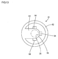
- FIG. 13 is a plan view of the valve member.
- a hydraulic lash adjuster A includes a cylinder 10, a plunger 20, and a non-return valve 30.
- the cylinder 10 is a cylinder having a base, and includes a disk-shaped base wall part 11, and a pipe-form circumferential wall part 12 that rises from a circumferential edge of the base wall part 11.
- the cylinder 10 is fixed into an attachment hole 41 provided in an upper surface of a cylinder head 40.
- An external through hole 13 is provided piercing the circumferential wall part 12 of the cylinder 10 in an internal-external direction.
- the external through hole 13 communicates with an operating oil supply way 42 provided in the cylinder head 40.
- the plunger 20 is a cylinder having a base, and includes a disk-shaped base wall part 21, and a pipe-form circumferential wall part 22 that rises from a circumferential edge of the base wall part 21.
- a low-pressure chamber 23 is provided in the plunger 20.
- a vertically pierced circular valve hole 24 is provided at a center of the base wall part 21 of the plunger 20.
- a horizontal (i.e. perpendicular to a movement direction of the plunger 20) seat surface 25 is provided around an edge of the valve hole 24 (see FIG. 2).
- a recessed portion 21a with an internal diameter larger than the valve hole 24 and a same center as the valve hole 24 is formed in the lower surface of the base wall part 21.
- a small diameter section 26 which has a smaller diameter than other sections, is formed in the circumferential wall 22 of the plunger 20. At the small diameter section 26, an internal through hole 27 pierces the circumferential wall 22 in an internal-external direction.
- Operating oil in the supply way 42 is supplied to the low-pressure chamber 23 by way of the external through hole 13, the small diameter part 26, and the internal through hole 27 in the order described.
- a substantially hemispherical (dome-form) supporting part 28 is formed at an upper end part of the plunger 20.
- a rocker arm (not shown in the drawings) contacts an external surface of the supporting part 28 from above. The rocker arm is arranged to oscillate with the supporting point 28 as a fulcrum.
- a circular air hole 29 vertically pierces a central region of an uppermost part of the supporting part 28.
- the plunger 20 is fitted into the cylinder 10.
- the plunger 20 is capable of movement in the up-down direction (an axial direction for the cylinder 10 and the plunger 20) while maintaining contact with an inner circumferential surface of the cylinder 10.
- a high-pressure chamber 14 is provided in an internal lower end part of the cylinder 10.
- the low-pressure chamber 23 and the high-pressure chamber 14 are separated by the base wall part 21 of the plunger 20.
- a non-return valve 30 for opening and closing the valve hole 24 is provided in the high-pressure chamber 14.
- the non-return valve 30 is constructed using a valve member 31.
- the valve member 31 is a plate-form metal member from which a predetermined section has been removed.
- the valve member 31 is a single body that includes a ring-form retainer part 32 and a substantially elliptical elastic bending piece 33.
- the retainer part 32 and the elastic bending piece 33 are formed to lie substantially in a same plane.
- a base end part (one end part) of the elastic bending piece 33 connects to the inner circumferential edge of the retainer part 32.
- a leading end part (the other end part) of the elastic banding piece 33 is substantially semi-circular, and an upper surface of the leading end part forms a seal surface 34.
- the elastic bending piece 33 is capable of deforming elastically in the up-down direction with the base end part as a fulcrum.
- the retainer part 32 is forcibly inserted in the recessed portion 21a of the plunger 20. This fixes the valve member 31 in the base wall part 21 of the plunger 20.
- an upper surface of the retainer part 32 and the upper surface of the elastic bending piece 33 are in surface contact with the lower surface of the base wall part 21 (a seat surface 25). Moreover, a lower surface side of the valve hole 24 is closed by the leading end part of the elastic bending piece 33.
- a return spring 35 constructed from a compression coil spring is provided in the high-pressure chamber 14.
- the return spring 35 is installed so as to have a same axis as the valve hole 24.
- the return spring 35 is formed using band-form spring wire 36.
- the spring wire 36 is a rectangle that is long in the horizontal direction. In plan view, the spring wire 36 forms a spiral.
- a coil diameter in the return spring 35 is largest at an upper end part, and becomes progressively smaller in a downwards direction.
- the return spring 35 is inverted-cone-shaped.
- the coil diameter of the return spring 35 is largest and is substantially the same as an inner diameter of the retainer part 32 in the valve member 31.
- the return spring 35 is elastically deformable in the up-down direction.
- the return spring 35 is formed so that, when in a state of maximum compression, the spring wire 36 that makes up the return spring 35 does not interfere with itself. This means that, when in the state of maximum compression, the total thickness of the return spring 35 is substantially the same as an up-down direction plate thickness of the spring wire 36.
- the return spring 35 is attached in an elastically compressed state between a lower surface of the retainer part 32 of the valve member 31 and a lower surface of the high-pressure chamber 14. Hence, the plunger 20 is always powered upwards by an elastic returning force stored in the return spring 35.
- the bending piece 33 elastically deforms so as to move downwards relative to the plunger 20. Since a gap then opens between the elastic bending piece 33 and the seat surface 25 (see FIG. 3), the operating oil flows from the low-pressure chamber 23 to the high-pressure chamber 14, and a state of the high-pressure chamber 14 being full of the operating oil is maintained.
- the elastic returning force generated in the elastic bending piece 33 causes the elastic bending piece 33 to return upwards and make contact with the seat surface 25. Since the valve hole 24 is then closed by the elastic bending piece 33, the high-pressure chamber 14 is in a closed state and full of the operating oil.
- an axial direction dimension (up-down direction dimension) of the return spring 35 when in the maximally compressed state is less than a dimension that is the thickness of the spring wire 36 multiplied by the number of coil turns.
- an overall height of the lash adjuster A can be reduced in comparison to a case in which a conventional return spring with a constant diameter of the coil diameter along an entire length is used.
- the coil diameter of the return spring 35 reduces progressively in a downwards direction from an uppermost end. Hence, when the elastic banding piece 33 that opens and closes the valve hole 24 has changed an up-down position in the high-pressure chamber 14, elastic bending piece 33 is prevented from interfering with the return spring 35.
- the substantially plate-form valve member 31 functions both as a valve body for opening and closing the valve hole 24, and as a valve spring for powering the valve body in a valve-closing direction. This eliminates the need for a spherical valve body and a valve spring to power the valve body from below. As a result, it becomes possible to reduce the height of the high-pressure chamber 14.
- the elastic bending piece 33 that forms the valve member 31 functions both as a valve body for opening and closing the valve hole 24, and as a valve spring for powering the valve body towards the valve hole 24.
- this construction has an advantage of using fewer parts than a construction in which separate parts are used for the valve body and the valve spring.
- the retainer part 32 of the valve member 31 is forcibly inserted into the recessed portion 21a of the base wall part 21. Hence, a dedicated part for fixing the valve member 31 to the base wall part 21 is unnecessary, and the advantage of a construction with fewer parts can be obtained.
- the retainer part 32 and the elastic bending piece 33 are formed in substantially the same plane, and have a substantial plate-like form, it is possible to reduce a thickness of the valve member 31 and the thus the height of the lash adjuster A.
- FIGS. 9 and 10 A second embodiment of the present invention is described with reference to FIGS. 9 and 10.
- valve member 50 and the seat surface 25a differ from corresponding parts in the first embodiment.
- parts that are substantially the same as those of the first embodiment are labeled with the same symbols, and a description of these parts is omitted.
- the vertically pierced circular valve hole 24 is provided at a center of the base wall part 21 of the plunger 20.
- An arc-form seat surface 25a is formed at a hole edge on a lower side (a high-pressure chamber 14 side) of the valve hole 24.
- the seat surface 25a has a diameter that increases progressively as a distance to the high-pressure chamber 14 side reduces, so as to have a downwardly widening profile.
- a valve member 51 that forms a non-return valve 50 is made up of a retainer part 52 and an elastic bending piece 53.
- a curved-surface (hemispherical) seal part 54 is formed on an upper surface of a free end of the elastic bending piece 53.
- a largest external diameter of the seal part 54 is larger than a smallest internal diameter of the valve hole 24.
- an external surface of the curved-surface seal part 54 makes line contact around a circle having substantially a same center as the valve hole 24.
- a valve member 61 that forms a non-return valve 60 differs from a corresponding part in the first embodiment, but other parts are substantially the same as corresponding parts in the first embodiment.
- parts that are substantially the same as those of the first embodiment are labeled with the same symbols, and a description of these parts is omitted.
- the valve member 61 that forms the non-return valve 60 is made up of a retainer part 62 and an elastic bending piece 63.
- a plurality (three in the present embodiment) of spring pieces 64 is provided so as to protrude in a diagonal upwards direction from an external circumferential edge part of a free end of the elastic bending piece 63 towards an exterior.
- the spring pieces 64 are capable of bending elastically.
- the spring pieces 64 are provided at a constant interval in a circumferential direction (at an interval of 90° in the present embodiment).
- a spherical valve body and a valve spring that is formed from a compression coil spring and powers the valve body from below may be used in place of the valve member.
- Spring wire having a circular cross-section may be used to form the return spring.
- the coil diameter may be set so that the spring wire in the coils makes partial contact with itself when the return spring is maximally compressed.
- the return spring is not limited to being an inverted-cone shape.
- a spindle shape in which a coil diameter is largest at an up-down direction middle section and becomes progressively smaller towards the top and bottom of the return spring, may be used.
- Another possibility is a drum shape in which the coil diameter is smallest at an up-down direction middle section and becomes progressively larger towards the top and bottom of the return spring.
- the return spring is not limited to having an inverted-cone shape in which the coil diameter progressively reduces from a top section to a bottom section.
- a return spring in which the coil diameter progressively increases from a top section to a bottom section may be used.
Abstract
Description
- The present invention relates to a hydraulic lash adjuster used in a valve train of an internal combustion engine.
- One well-known hydraulic lash adjuster is described in
Japanese Patent Laid-Open No. 61-066811 - In the above-described lash adjuster, a spherical valve body and a return spring are provided in the high-pressure chamber. The return spring powers the valve body in the upwards direction so that the valve body closes the valve hole. Together the valve body and the return spring form a non-return valve for opening and closing the valve hole.
- When the rocker arm is pressing down the plunger, the valve hole is closed by the valve body, and the high-pressure chamber is in sealed state. Thus, oil pressure in the operating oil that fills the high-pressure chamber supports the plunger, preventing downwards movement.
- When the rocker arm is not pressing down the plunger, the valve body moves downwards, opening the valve hole, and so operating oil flows into the high-pressure chamber from the low-pressure chamber. Thus, the volume of the high-pressure chamber increases, and the plunger is allowed to rise.
- In the above-described conventional lash adjuster, the return spring provided in the high-pressure chamber is a compression coil spring. A coil diameter of the compression coil spring is constant along an entire length (from an upper end to a lower end). Hence, a return spring axial direction (the up-down direction) dimension when the plunger is down and the return spring is in a maximally compressed state corresponds to a dimension that is a number windings multiplied by a thickness of the spring wire.
- It should be noted that a high-pressure chamber height must accommodate at least the up-down dimension of the return spring when in a maximally compressed state and a plunger stroke length in the up-down direction. Therefore, when the up-down direction dimension of the return spring is large, the height of the high-pressure chamber increases, and an overall height of the lash adjuster has to increase.
- The present invention was conceived after considering the above-described problem, and has an object of reducing the height of the lash adjuster.
- A first invention is a lash adjuster including: a cylinder having a base; a plunger that is movable up and down in contact with an inner circumferential peripheral surface of the cylinder; a low-pressure chamber provided in the plunger; a high-pressure chamber provided in a lower end part of the cylinder; a return spring provided in the high-pressure chamber; and a non-return valve that opens and closes a valve hole provided in a base wall of the plunger, wherein the low-pressure chamber holds operating oil, the high-pressure chamber is filled with the operating oil, the high-pressure chamber and the low-pressure chamber are separated by the base wall of the plunger, the return spring is a compression coil spring provided so that its axial direction aligns with the up-down direction, the return spring is provided in the high-pressure chamber, the return spring powers the plunger in an upwards direction, and the return spring has a coil diameter that varies along the axial direction.
- According to the first invention, the coil diameter varies along the axial direction, and so the axial direction (up-down direction) dimension of the return spring when in a maximally compressed state is smaller than a dimension that is the spring wire thickness multiplied by the number of windings. The height of the high-pressure chamber, and as a result, the height of the entire lash adjuster can therefore be reduced.
- A second invention is a lash adjuster in which the coil diameter of the return spring becomes progressively smaller from a top section to a bottom section.
- According to the second invention, the coil diameter of the return spring becomes progressively smaller from a top section to a bottom section, and so contact interference between the non-return valve and the return spring can be avoided.
- A third invention is a lash adjuster characterized in which the non-return valve is constructed from a valve member provided in the high-pressure chamber, the valve member is a single body that includes a retainer part fixed to the plunger base wall and an elastic bending piece that opens and closes the valve hole by bending in the up-down direction.
- According to the third invention, the valve member is formed from a single body that includes a retainer part and an elastic bending piece, and so a number of parts that make up a valve member can be reduced (in other words, the conventional construction of the non-return valve in which a valve spring powers the spherical valve body towards the valve hole is no longer necessary).
- The fourth invention is a lash adjuster in which the retainer part and the elastic bending piece are formed in substantially a same plane, and are substantial plate-like.
- According to the fourth invention, a thickness of the valve member can be reduced. Hence, the height of the lash adjuster can be reduced.
- The fifth invention is a lash adjuster in which a seal part with a curved surface is formed on the elastic bending piece, and the seal part is line-contactable with an edge of the valve hole.
- According to the fifth invention, the seal part formed on the elastic bending piece is line-contactable with an edge of the valve hole, and so the sealing of the valve hole is favorable.
- The sixth invention is a lash adjuster in which a recessed portion is provided in a lower surface of the base wall of the plunger, and the retainer part is forcibly inserted into the recessed portion.
- According to the sixth invention, a dedicated part is not required as a means to fix the retainer part to the base wall, and so the number of parts can be reduced.
- FIG. 1 is cross-sectional diagram of a lash adjuster of a first embodiment;
- FIG. 2 is an enlarged partial cross-sectional diagram showing a non-return valve in a closed state;
- FIG. 3 is an enlarged partial cross-sectional diagram showing the non-return valve in an open state;
- FIG. 4 is an enlarged partial cross-sectional diagram showing the non-return valve in a closed state and the plunger in a pushed-down state;
- FIG. 5 shows a cross-section through X-X with a return spring omitted;
- FIG. 6 shows a cross-section through X-X with valve member omitted;
- FIG. 7 is a plan view of a valve member;
- FIG. 8 is a plan view of the return spring;
- FIG. 9 is an enlarged partial cross-sectional diagram of a lash adjuster of a second embodiment;
- FIG. 10 is a cross-section through Y-Y of FIG. 9;
- FIG. 11 is an enlarged partial cross-sectional diagram showing the non-return valve of a third embodiment in a closed state;
- FIG. 12 is an enlarged partial cross-sectional diagram showing the non-return valve of the third embodiment in an open state; and
- FIG. 13 is a plan view of the valve member.
- The following describes a first embodiment of the present invention with reference to FIGS. 1 to 8.
- As shown in FIG. 1, a hydraulic lash adjuster A includes a
cylinder 10, aplunger 20, and anon-return valve 30. - The
cylinder 10 is a cylinder having a base, and includes a disk-shapedbase wall part 11, and a pipe-formcircumferential wall part 12 that rises from a circumferential edge of thebase wall part 11. - The
cylinder 10 is fixed into anattachment hole 41 provided in an upper surface of acylinder head 40. - An external through
hole 13 is provided piercing thecircumferential wall part 12 of thecylinder 10 in an internal-external direction. The external throughhole 13 communicates with an operatingoil supply way 42 provided in thecylinder head 40. - The
plunger 20 is a cylinder having a base, and includes a disk-shapedbase wall part 21, and a pipe-formcircumferential wall part 22 that rises from a circumferential edge of thebase wall part 21. - A low-
pressure chamber 23 is provided in theplunger 20. - A vertically pierced
circular valve hole 24 is provided at a center of thebase wall part 21 of theplunger 20. - On a lower surface (a surface facing a high-
pressure chamber 14, which is described later) of thebase wall part 21, a horizontal (i.e. perpendicular to a movement direction of the plunger 20)seat surface 25 is provided around an edge of the valve hole 24 (see FIG. 2). - Also, a
recessed portion 21a with an internal diameter larger than thevalve hole 24 and a same center as thevalve hole 24 is formed in the lower surface of thebase wall part 21. - A
small diameter section 26, which has a smaller diameter than other sections, is formed in thecircumferential wall 22 of theplunger 20. At thesmall diameter section 26, an internal throughhole 27 pierces thecircumferential wall 22 in an internal-external direction. - Operating oil in the
supply way 42 is supplied to the low-pressure chamber 23 by way of the external throughhole 13, thesmall diameter part 26, and the internal throughhole 27 in the order described. - A substantially hemispherical (dome-form) supporting
part 28 is formed at an upper end part of theplunger 20. A rocker arm (not shown in the drawings) contacts an external surface of the supportingpart 28 from above. The rocker arm is arranged to oscillate with the supportingpoint 28 as a fulcrum. Acircular air hole 29 vertically pierces a central region of an uppermost part of the supportingpart 28. - The
plunger 20 is fitted into thecylinder 10. Theplunger 20 is capable of movement in the up-down direction (an axial direction for thecylinder 10 and the plunger 20) while maintaining contact with an inner circumferential surface of thecylinder 10. - A high-
pressure chamber 14 is provided in an internal lower end part of thecylinder 10. The low-pressure chamber 23 and the high-pressure chamber 14 are separated by thebase wall part 21 of theplunger 20. - A
non-return valve 30 for opening and closing thevalve hole 24 is provided in the high-pressure chamber 14. Thenon-return valve 30 is constructed using avalve member 31. - As shown in FIG. 5, the
valve member 31 is a plate-form metal member from which a predetermined section has been removed. Thevalve member 31 is a single body that includes a ring-form retainer part 32 and a substantially ellipticalelastic bending piece 33. Theretainer part 32 and theelastic bending piece 33 are formed to lie substantially in a same plane. - A base end part (one end part) of the
elastic bending piece 33 connects to the inner circumferential edge of theretainer part 32. A leading end part (the other end part) of theelastic banding piece 33 is substantially semi-circular, and an upper surface of the leading end part forms aseal surface 34. Theelastic bending piece 33 is capable of deforming elastically in the up-down direction with the base end part as a fulcrum. - As shown in FIG. 2, the
retainer part 32 is forcibly inserted in the recessedportion 21a of theplunger 20. This fixes thevalve member 31 in thebase wall part 21 of theplunger 20. - When the
valve member 31 has been fixed in place, an upper surface of theretainer part 32 and the upper surface of the elastic bending piece 33 (the seal surface 34) are in surface contact with the lower surface of the base wall part 21 (a seat surface 25). Moreover, a lower surface side of thevalve hole 24 is closed by the leading end part of theelastic bending piece 33. - As shown in FIGS. 2 and 3, a
return spring 35 constructed from a compression coil spring is provided in the high-pressure chamber 14. Thereturn spring 35 is installed so as to have a same axis as thevalve hole 24. Thereturn spring 35 is formed using band-form spring wire 36. In cross-section, thespring wire 36 is a rectangle that is long in the horizontal direction. In plan view, thespring wire 36 forms a spiral. - A coil diameter in the
return spring 35 is largest at an upper end part, and becomes progressively smaller in a downwards direction. In other words thereturn spring 35 is inverted-cone-shaped. - Thus, at an uppermost end, the coil diameter of the
return spring 35 is largest and is substantially the same as an inner diameter of theretainer part 32 in thevalve member 31. - The
return spring 35 is elastically deformable in the up-down direction. Thereturn spring 35 is formed so that, when in a state of maximum compression, thespring wire 36 that makes up thereturn spring 35 does not interfere with itself. This means that, when in the state of maximum compression, the total thickness of thereturn spring 35 is substantially the same as an up-down direction plate thickness of thespring wire 36. - The
return spring 35 is attached in an elastically compressed state between a lower surface of theretainer part 32 of thevalve member 31 and a lower surface of the high-pressure chamber 14. Hence, theplunger 20 is always powered upwards by an elastic returning force stored in thereturn spring 35. - As shown in FIG. 4, when the
plunger 20 is maximally compressed within a normal-use range for a lash adjuster A (i.e. theplunger 20 is in a fully pushed-down state), a inverted-cone-shapedspace 37 formed by thespring wire 36 is maintained below theelastic bending piece 33. Thus, even when theelastic bending piece 33 is elastically deformed downwards, interference with thespring wire 36 is prevented. - The following describes operations of the lash adjuster A of the present embodiment.
- When a pressing force from a rocker arm side is working in a downward direction on the
plunger 20, theelastic bending piece 33 is in contact with theseat surface 25, and thevalve hole 24 is closed. Since the high-pressure chamber 14 is then in a closed state, downwards movement of theplunger 20 is prevented by the operating oil that fills the high-pressure chamber 14 (see FIG. 2). - Conversely, when the
plunger 20 has risen, and a volume of the high-pressure chamber 14 has increased, the bendingpiece 33 elastically deforms so as to move downwards relative to theplunger 20. Since a gap then opens between theelastic bending piece 33 and the seat surface 25 (see FIG. 3), the operating oil flows from the low-pressure chamber 23 to the high-pressure chamber 14, and a state of the high-pressure chamber 14 being full of the operating oil is maintained. - When the rise of the
plunger 20 stops, the elastic returning force generated in theelastic bending piece 33 causes theelastic bending piece 33 to return upwards and make contact with theseat surface 25. Since thevalve hole 24 is then closed by theelastic bending piece 33, the high-pressure chamber 14 is in a closed state and full of the operating oil. - Since the coil diameter of the
return spring 35 varies along the axial direction, an axial direction dimension (up-down direction dimension) of thereturn spring 35 when in the maximally compressed state is less than a dimension that is the thickness of thespring wire 36 multiplied by the number of coil turns. Hence, an overall height of the lash adjuster A can be reduced in comparison to a case in which a conventional return spring with a constant diameter of the coil diameter along an entire length is used. - The coil diameter of the
return spring 35 reduces progressively in a downwards direction from an uppermost end. Hence, when theelastic banding piece 33 that opens and closes thevalve hole 24 has changed an up-down position in the high-pressure chamber 14,elastic bending piece 33 is prevented from interfering with thereturn spring 35. - The substantially plate-
form valve member 31 functions both as a valve body for opening and closing thevalve hole 24, and as a valve spring for powering the valve body in a valve-closing direction. This eliminates the need for a spherical valve body and a valve spring to power the valve body from below. As a result, it becomes possible to reduce the height of the high-pressure chamber 14. - The
elastic bending piece 33 that forms thevalve member 31 functions both as a valve body for opening and closing thevalve hole 24, and as a valve spring for powering the valve body towards thevalve hole 24. Hence, this construction has an advantage of using fewer parts than a construction in which separate parts are used for the valve body and the valve spring. - The
retainer part 32 of thevalve member 31 is forcibly inserted into the recessedportion 21a of thebase wall part 21. Hence, a dedicated part for fixing thevalve member 31 to thebase wall part 21 is unnecessary, and the advantage of a construction with fewer parts can be obtained. - Since the
retainer part 32 and theelastic bending piece 33 are formed in substantially the same plane, and have a substantial plate-like form, it is possible to reduce a thickness of thevalve member 31 and the thus the height of the lash adjuster A. - A second embodiment of the present invention is described with reference to FIGS. 9 and 10.
- As shown in FIGS. 9 and 10, in the lash adjuster B of the second embodiment, the
valve member 50 and theseat surface 25a differ from corresponding parts in the first embodiment. In the following, parts that are substantially the same as those of the first embodiment are labeled with the same symbols, and a description of these parts is omitted. - The vertically pierced
circular valve hole 24 is provided at a center of thebase wall part 21 of theplunger 20. An arc-form seat surface 25a is formed at a hole edge on a lower side (a high-pressure chamber 14 side) of thevalve hole 24. Theseat surface 25a has a diameter that increases progressively as a distance to the high-pressure chamber 14 side reduces, so as to have a downwardly widening profile. - A
valve member 51 that forms anon-return valve 50, like thevalve member 31 of the first embodiment, is made up of aretainer part 52 and anelastic bending piece 53. - A curved-surface (hemispherical)
seal part 54 is formed on an upper surface of a free end of theelastic bending piece 53. A largest external diameter of theseal part 54 is larger than a smallest internal diameter of thevalve hole 24. - When the
non-return valve 30 is closing thevalve hole 24, an external surface of the curved-surface seal part 54 makes line contact around a circle having substantially a same center as thevalve hole 24. - Since, in the lash adjuster B of the second embodiment, the
elastic bending piece 53 and the hole edge (theseat surface 25a) of thevalve hole 24 are in line contact, sealing of thevalve hole 24 is favorable in comparison to when surface contact is used. - The following describes a third embodiment of the present invention with reference to FIGS. 11 to 13.
- As shown in FIGS. 11 to 13, in a lash adjuster C of a third embodiment, a
valve member 61 that forms anon-return valve 60 differs from a corresponding part in the first embodiment, but other parts are substantially the same as corresponding parts in the first embodiment. Thus, in the following, parts that are substantially the same as those of the first embodiment are labeled with the same symbols, and a description of these parts is omitted. - The
valve member 61 that forms thenon-return valve 60, like thevalve member 31 of the first embodiment, is made up of aretainer part 62 and anelastic bending piece 63. - On the
elastic bending piece 63, a plurality (three in the present embodiment) ofspring pieces 64 is provided so as to protrude in a diagonal upwards direction from an external circumferential edge part of a free end of theelastic bending piece 63 towards an exterior. Thespring pieces 64 are capable of bending elastically. Thespring pieces 64 are provided at a constant interval in a circumferential direction (at an interval of 90° in the present embodiment). - As shown in FIG. 12, when a pressing force is being strongly applied from the rocker-arm side downwards on the
plunger 20, thespring pieces 64 elastically deform, and make surface contacts with theseat surface 25. At this point, theelastic bending piece 63 and thespring pieces 64 are in a substantially same plane, and aseal surface 65 of the bendingpiece 63 is in surface contact with theseat surface 25. As a result, thevalve hole 24 is completely closed by thenon-return valve 60, and the flow of operating oil between the low-pressure chamber 23 and the high-pressure chamber 14 is blocked. - As shown in FIG. 11, when a pressing force is being weakly applied from the rocker-arm side downwards on the
plunger 20, thespring pieces 64 hardly elastically deform at all, and so the leading ends (free ends) of thespring pieces 64 are in line contact or point contact with theseat surface 25. At this point, a small gap corresponding to a height of thespring pieces 64 is secured between an upper surface (the seal surface 25) of theelastic bending piece 63 and theseat surface 25. This secures a flow of a small amount of operating oil between the low-pressure chamber 23 and the high-pressure chamber 14. - When the
plunger 20 moves upwards, theelastic bending piece 63 elastically deforms downwards by a large amount, and so thespring parts 64 separate from theseat surface 25. - The present invention is not limited to the embodiments that are described above with reference to the drawings. Examples of the type described below are also included within the technical scope of the present invention.
- (1) A spherical valve body and a valve spring that is formed from a compression coil spring and powers the valve body from below may be used in place of the valve member.
- (2) Spring wire having a circular cross-section may be used to form the return spring. When spring wire with a circular cross-section is used, the coil diameter may be set so that the spring wire in the coils makes partial contact with itself when the return spring is maximally compressed.
- (3) The return spring is not limited to being an inverted-cone shape. A spindle shape, in which a coil diameter is largest at an up-down direction middle section and becomes progressively smaller towards the top and bottom of the return spring, may be used. Another possibility is a drum shape in which the coil diameter is smallest at an up-down direction middle section and becomes progressively larger towards the top and bottom of the return spring.
- (4) The return spring is not limited to having an inverted-cone shape in which the coil diameter progressively reduces from a top section to a bottom section. A return spring in which the coil diameter progressively increases from a top section to a bottom section may be used.
Claims (6)
- A lash adjuster comprising:a cylinder having a base;a plunger that is movable up and down in contact with an internal peripheral surface of the cylinder;a low-pressure chamber provided in the plunger;a high-pressure chamber provided in a lower end part of the cylinder;a return spring provided in the high-pressure chamber; anda non-return valve that opens and closes a valve hole provided in a base wall of the plunger, whereinthe low-pressure chamber holds operating oil,the high-pressure chamber is filled with the operating oil,the high-pressure chamber and the low-pressure chamber are separated by the base wall of the plunger,the return spring is a compression coil spring provided so that its axial direction aligns with the up-down direction,the return spring is provided in the high-pressure chamber,the return spring powers the plunger in an upwards direction, andthe return spring has a coil diameter that varies along the axial direction.
- The lash adjuster according to claim 1, wherein
the coil diameter of the return spring becomes progressively smaller from a top section to a bottom section. - The lash adjuster according to claim 1 or 2, wherein
the non-return valve is constructed from a valve member provided in the high-pressure chamber,
the valve member is a single body that includes a retainer part fixed to the plunger base wall and an elastic bending piece that opens and closes the valve hole by bending in the up-down direction. - The lash adjuster according to claim 3, wherein
the retainer part and the elastic bending piece are formed in substantially a same plane, and are substantial plate-like. - The lash adjuster according to claim 3, wherein
a seal part with a curved surface is formed on the elastic bending piece, and
the seal part is line-contactable with an edge of the valve hole. - The lash adjuster according to claims 3 to 5, wherein
a recessed portion is provided in a lower surface of the base wall of the plunger, and
the retainer part is forcibly inserted into the recessed portion.
Applications Claiming Priority (1)
| Application Number | Priority Date | Filing Date | Title |
|---|---|---|---|
| JP2006254752A JP2008075519A (en) | 2006-09-20 | 2006-09-20 | Lash adjuster |
Publications (3)
| Publication Number | Publication Date |
|---|---|
| EP1903190A2 true EP1903190A2 (en) | 2008-03-26 |
| EP1903190A3 EP1903190A3 (en) | 2009-04-29 |
| EP1903190B1 EP1903190B1 (en) | 2012-02-22 |
Family
ID=38859087
Family Applications (1)
| Application Number | Title | Priority Date | Filing Date |
|---|---|---|---|
| EP07017150A Not-in-force EP1903190B1 (en) | 2006-09-20 | 2007-08-31 | Lash adjuster |
Country Status (4)
| Country | Link |
|---|---|
| US (1) | US8056524B2 (en) |
| EP (1) | EP1903190B1 (en) |
| JP (1) | JP2008075519A (en) |
| AT (1) | ATE546618T1 (en) |
Families Citing this family (2)
| Publication number | Priority date | Publication date | Assignee | Title |
|---|---|---|---|---|
| JP5110032B2 (en) | 2009-04-17 | 2012-12-26 | 富士通株式会社 | Enclosure |
| JP5313040B2 (en) * | 2009-05-18 | 2013-10-09 | 株式会社オティックス | Rush adjuster |
Citations (3)
| Publication number | Priority date | Publication date | Assignee | Title |
|---|---|---|---|---|
| US4864982A (en) | 1983-02-10 | 1989-09-12 | Motomak Motorenbau, Maschinen- Und Werkzeugfabrik, Konstruktionen Gmbh | Inner element for an hydraulic valve play compensation element |
| EP0608925A1 (en) | 1993-01-28 | 1994-08-03 | General Motors Corporation | Compact valve-lifters |
| EP1267046A1 (en) | 2001-06-15 | 2002-12-18 | EATON AUTOMOTIVE S.p.A. | Hydraulic lash adjuster |
Family Cites Families (10)
| Publication number | Priority date | Publication date | Assignee | Title |
|---|---|---|---|---|
| GB751705A (en) * | 1953-11-12 | 1956-07-04 | Eaton Mfg Co | Improvements in or relating to a hydraulic tappet for an internal combustion engine valve gear |
| US3262434A (en) | 1963-03-02 | 1966-07-26 | Motomak Motorenbau Maschinenun | Self-adjusting hydraulic valve lifter for piston engines |
| US3267918A (en) * | 1964-08-03 | 1966-08-23 | Eaton Mfg Co | Fluid metering valve structure |
| JPS6166811A (en) | 1984-09-07 | 1986-04-05 | Odai Tekko Kk | Tappet mechanism with suspension function in internal-combustion engine |
| US4807575A (en) * | 1987-11-23 | 1989-02-28 | General Motors Corporation | Hydraulic lash adjuster with multi-directional check valve |
| JPH03172633A (en) | 1989-11-30 | 1991-07-26 | Masao Akimoto | Helical spring |
| JPH0510257A (en) * | 1991-07-03 | 1993-01-19 | Toyota Autom Loom Works Ltd | Valve device for reciprocating compressor |
| JPH05318012A (en) | 1992-05-19 | 1993-12-03 | Toshiba Corp | Spring and manufacture thereof |
| US6006710A (en) * | 1998-08-31 | 1999-12-28 | Ford Global Technologies, Inc. | Hydraulic lash adjuster mechanism with pressure controlled leak down |
| EP1267045A1 (en) * | 2001-06-15 | 2002-12-18 | EATON AUTOMOTIVE S.p.A. | Hydraulic lash adjuster for a valve train in an internal combustion engine |
-
2006
- 2006-09-20 JP JP2006254752A patent/JP2008075519A/en active Pending
-
2007
- 2007-08-31 AT AT07017150T patent/ATE546618T1/en active
- 2007-08-31 EP EP07017150A patent/EP1903190B1/en not_active Not-in-force
- 2007-09-06 US US11/896,896 patent/US8056524B2/en not_active Expired - Fee Related
Patent Citations (3)
| Publication number | Priority date | Publication date | Assignee | Title |
|---|---|---|---|---|
| US4864982A (en) | 1983-02-10 | 1989-09-12 | Motomak Motorenbau, Maschinen- Und Werkzeugfabrik, Konstruktionen Gmbh | Inner element for an hydraulic valve play compensation element |
| EP0608925A1 (en) | 1993-01-28 | 1994-08-03 | General Motors Corporation | Compact valve-lifters |
| EP1267046A1 (en) | 2001-06-15 | 2002-12-18 | EATON AUTOMOTIVE S.p.A. | Hydraulic lash adjuster |
Also Published As
| Publication number | Publication date |
|---|---|
| US8056524B2 (en) | 2011-11-15 |
| JP2008075519A (en) | 2008-04-03 |
| EP1903190A3 (en) | 2009-04-29 |
| EP1903190B1 (en) | 2012-02-22 |
| ATE546618T1 (en) | 2012-03-15 |
| US20080066705A1 (en) | 2008-03-20 |
Similar Documents
| Publication | Publication Date | Title |
|---|---|---|
| US8955550B2 (en) | Damper device | |
| EP1657438B1 (en) | High pressure fuel pump | |
| US8863716B2 (en) | Tappet | |
| EP2267281B1 (en) | Rocker arm unit and method of assembling rocker arm unit | |
| EP0030781A1 (en) | Hydraulic tappet for direct-acting valve gear | |
| KR101570889B1 (en) | Lash adjuster | |
| EP2295738A1 (en) | Rocker arm unit | |
| JP6050698B2 (en) | Rush adjuster | |
| EP1903190A2 (en) | Lash adjuster | |
| JP4865740B2 (en) | Rush adjuster | |
| US20220082072A1 (en) | Metal Diaphragm Metal Damper and Fuel Pump Provided With Same | |
| EP3078819B1 (en) | Lash adjuster | |
| US20070272185A1 (en) | Hydraulic lash adjuster for an internal combustion engine | |
| US4715334A (en) | Self contained hydraulic bucket lifter | |
| US6536391B2 (en) | Compact hydraulic lash adjuster | |
| US20050183686A1 (en) | Hydraulic lash adjuster | |
| JP4731521B2 (en) | Rash adjuster and retainer assembly method | |
| JP7264757B2 (en) | valve train | |
| JP5313040B2 (en) | Rush adjuster | |
| CN213205782U (en) | Check valve and hydraulic lash adjuster | |
| JP2020023916A (en) | Tappet structure | |
| JP2005221000A (en) | Sealed hydraulic damper | |
| JP6599735B2 (en) | Rush adjuster | |
| JPS59162311A (en) | Sealed type oil-hydraulic lifter | |
| JP2003083010A (en) | Hydraulic lash adjuster |
Legal Events
| Date | Code | Title | Description |
|---|---|---|---|
| PUAI | Public reference made under article 153(3) epc to a published international application that has entered the european phase |
Free format text: ORIGINAL CODE: 0009012 |
|
| AK | Designated contracting states |
Kind code of ref document: A2 Designated state(s): AT BE BG CH CY CZ DE DK EE ES FI FR GB GR HU IE IS IT LI LT LU LV MC MT NL PL PT RO SE SI SK TR |
|
| AX | Request for extension of the european patent |
Extension state: AL BA HR MK YU |
|
| PUAL | Search report despatched |
Free format text: ORIGINAL CODE: 0009013 |
|
| AK | Designated contracting states |
Kind code of ref document: A3 Designated state(s): AT BE BG CH CY CZ DE DK EE ES FI FR GB GR HU IE IS IT LI LT LU LV MC MT NL PL PT RO SE SI SK TR |
|
| AX | Request for extension of the european patent |
Extension state: AL BA HR MK RS |
|
| 17P | Request for examination filed |
Effective date: 20091029 |
|
| AKX | Designation fees paid |
Designated state(s): AT BE BG CH CY CZ DE DK EE ES FI FR GB GR HU IE IS IT LI LT LU LV MC MT NL PL PT RO SE SI SK TR |
|
| GRAP | Despatch of communication of intention to grant a patent |
Free format text: ORIGINAL CODE: EPIDOSNIGR1 |
|
| GRAS | Grant fee paid |
Free format text: ORIGINAL CODE: EPIDOSNIGR3 |
|
| GRAA | (expected) grant |
Free format text: ORIGINAL CODE: 0009210 |
|
| AK | Designated contracting states |
Kind code of ref document: B1 Designated state(s): AT BE BG CH CY CZ DE DK EE ES FI FR GB GR HU IE IS IT LI LT LU LV MC MT NL PL PT RO SE SI SK TR |
|
| REG | Reference to a national code |
Ref country code: GB Ref legal event code: FG4D |
|
| REG | Reference to a national code |
Ref country code: CH Ref legal event code: EP |
|
| REG | Reference to a national code |
Ref country code: AT Ref legal event code: REF Ref document number: 546618 Country of ref document: AT Kind code of ref document: T Effective date: 20120315 |
|
| REG | Reference to a national code |
Ref country code: IE Ref legal event code: FG4D |
|
| REG | Reference to a national code |
Ref country code: DE Ref legal event code: R096 Ref document number: 602007020794 Country of ref document: DE Effective date: 20120419 |
|
| REG | Reference to a national code |
Ref country code: NL Ref legal event code: VDEP Effective date: 20120222 |
|
| LTIE | Lt: invalidation of european patent or patent extension |
Effective date: 20120222 |
|
| PG25 | Lapsed in a contracting state [announced via postgrant information from national office to epo] |
Ref country code: IS Free format text: LAPSE BECAUSE OF FAILURE TO SUBMIT A TRANSLATION OF THE DESCRIPTION OR TO PAY THE FEE WITHIN THE PRESCRIBED TIME-LIMIT Effective date: 20120622 Ref country code: LT Free format text: LAPSE BECAUSE OF FAILURE TO SUBMIT A TRANSLATION OF THE DESCRIPTION OR TO PAY THE FEE WITHIN THE PRESCRIBED TIME-LIMIT Effective date: 20120222 Ref country code: NL Free format text: LAPSE BECAUSE OF FAILURE TO SUBMIT A TRANSLATION OF THE DESCRIPTION OR TO PAY THE FEE WITHIN THE PRESCRIBED TIME-LIMIT Effective date: 20120222 |
|
| PG25 | Lapsed in a contracting state [announced via postgrant information from national office to epo] |
Ref country code: PT Free format text: LAPSE BECAUSE OF FAILURE TO SUBMIT A TRANSLATION OF THE DESCRIPTION OR TO PAY THE FEE WITHIN THE PRESCRIBED TIME-LIMIT Effective date: 20120622 Ref country code: FI Free format text: LAPSE BECAUSE OF FAILURE TO SUBMIT A TRANSLATION OF THE DESCRIPTION OR TO PAY THE FEE WITHIN THE PRESCRIBED TIME-LIMIT Effective date: 20120222 Ref country code: BE Free format text: LAPSE BECAUSE OF FAILURE TO SUBMIT A TRANSLATION OF THE DESCRIPTION OR TO PAY THE FEE WITHIN THE PRESCRIBED TIME-LIMIT Effective date: 20120222 Ref country code: GR Free format text: LAPSE BECAUSE OF FAILURE TO SUBMIT A TRANSLATION OF THE DESCRIPTION OR TO PAY THE FEE WITHIN THE PRESCRIBED TIME-LIMIT Effective date: 20120523 Ref country code: LV Free format text: LAPSE BECAUSE OF FAILURE TO SUBMIT A TRANSLATION OF THE DESCRIPTION OR TO PAY THE FEE WITHIN THE PRESCRIBED TIME-LIMIT Effective date: 20120222 |
|
| REG | Reference to a national code |
Ref country code: AT Ref legal event code: MK05 Ref document number: 546618 Country of ref document: AT Kind code of ref document: T Effective date: 20120222 |
|
| PG25 | Lapsed in a contracting state [announced via postgrant information from national office to epo] |
Ref country code: CY Free format text: LAPSE BECAUSE OF FAILURE TO SUBMIT A TRANSLATION OF THE DESCRIPTION OR TO PAY THE FEE WITHIN THE PRESCRIBED TIME-LIMIT Effective date: 20120222 |
|
| PG25 | Lapsed in a contracting state [announced via postgrant information from national office to epo] |
Ref country code: PL Free format text: LAPSE BECAUSE OF FAILURE TO SUBMIT A TRANSLATION OF THE DESCRIPTION OR TO PAY THE FEE WITHIN THE PRESCRIBED TIME-LIMIT Effective date: 20120222 Ref country code: DK Free format text: LAPSE BECAUSE OF FAILURE TO SUBMIT A TRANSLATION OF THE DESCRIPTION OR TO PAY THE FEE WITHIN THE PRESCRIBED TIME-LIMIT Effective date: 20120222 Ref country code: SI Free format text: LAPSE BECAUSE OF FAILURE TO SUBMIT A TRANSLATION OF THE DESCRIPTION OR TO PAY THE FEE WITHIN THE PRESCRIBED TIME-LIMIT Effective date: 20120222 Ref country code: SE Free format text: LAPSE BECAUSE OF FAILURE TO SUBMIT A TRANSLATION OF THE DESCRIPTION OR TO PAY THE FEE WITHIN THE PRESCRIBED TIME-LIMIT Effective date: 20120222 Ref country code: RO Free format text: LAPSE BECAUSE OF FAILURE TO SUBMIT A TRANSLATION OF THE DESCRIPTION OR TO PAY THE FEE WITHIN THE PRESCRIBED TIME-LIMIT Effective date: 20120222 Ref country code: EE Free format text: LAPSE BECAUSE OF FAILURE TO SUBMIT A TRANSLATION OF THE DESCRIPTION OR TO PAY THE FEE WITHIN THE PRESCRIBED TIME-LIMIT Effective date: 20120222 Ref country code: CZ Free format text: LAPSE BECAUSE OF FAILURE TO SUBMIT A TRANSLATION OF THE DESCRIPTION OR TO PAY THE FEE WITHIN THE PRESCRIBED TIME-LIMIT Effective date: 20120222 |
|
| PG25 | Lapsed in a contracting state [announced via postgrant information from national office to epo] |
Ref country code: SK Free format text: LAPSE BECAUSE OF FAILURE TO SUBMIT A TRANSLATION OF THE DESCRIPTION OR TO PAY THE FEE WITHIN THE PRESCRIBED TIME-LIMIT Effective date: 20120222 Ref country code: IT Free format text: LAPSE BECAUSE OF FAILURE TO SUBMIT A TRANSLATION OF THE DESCRIPTION OR TO PAY THE FEE WITHIN THE PRESCRIBED TIME-LIMIT Effective date: 20120222 |
|
| PLBE | No opposition filed within time limit |
Free format text: ORIGINAL CODE: 0009261 |
|
| STAA | Information on the status of an ep patent application or granted ep patent |
Free format text: STATUS: NO OPPOSITION FILED WITHIN TIME LIMIT |
|
| 26N | No opposition filed |
Effective date: 20121123 |
|
| PG25 | Lapsed in a contracting state [announced via postgrant information from national office to epo] |
Ref country code: AT Free format text: LAPSE BECAUSE OF FAILURE TO SUBMIT A TRANSLATION OF THE DESCRIPTION OR TO PAY THE FEE WITHIN THE PRESCRIBED TIME-LIMIT Effective date: 20120222 |
|
| REG | Reference to a national code |
Ref country code: DE Ref legal event code: R097 Ref document number: 602007020794 Country of ref document: DE Effective date: 20121123 |
|
| REG | Reference to a national code |
Ref country code: CH Ref legal event code: PL |
|
| PG25 | Lapsed in a contracting state [announced via postgrant information from national office to epo] |
Ref country code: MC Free format text: LAPSE BECAUSE OF NON-PAYMENT OF DUE FEES Effective date: 20120831 |
|
| PG25 | Lapsed in a contracting state [announced via postgrant information from national office to epo] |
Ref country code: CH Free format text: LAPSE BECAUSE OF NON-PAYMENT OF DUE FEES Effective date: 20120831 Ref country code: ES Free format text: LAPSE BECAUSE OF FAILURE TO SUBMIT A TRANSLATION OF THE DESCRIPTION OR TO PAY THE FEE WITHIN THE PRESCRIBED TIME-LIMIT Effective date: 20120602 Ref country code: LI Free format text: LAPSE BECAUSE OF NON-PAYMENT OF DUE FEES Effective date: 20120831 |
|
| REG | Reference to a national code |
Ref country code: IE Ref legal event code: MM4A |
|
| PG25 | Lapsed in a contracting state [announced via postgrant information from national office to epo] |
Ref country code: IE Free format text: LAPSE BECAUSE OF NON-PAYMENT OF DUE FEES Effective date: 20120831 Ref country code: BG Free format text: LAPSE BECAUSE OF FAILURE TO SUBMIT A TRANSLATION OF THE DESCRIPTION OR TO PAY THE FEE WITHIN THE PRESCRIBED TIME-LIMIT Effective date: 20120522 |
|
| PG25 | Lapsed in a contracting state [announced via postgrant information from national office to epo] |
Ref country code: MT Free format text: LAPSE BECAUSE OF FAILURE TO SUBMIT A TRANSLATION OF THE DESCRIPTION OR TO PAY THE FEE WITHIN THE PRESCRIBED TIME-LIMIT Effective date: 20120222 |
|
| PG25 | Lapsed in a contracting state [announced via postgrant information from national office to epo] |
Ref country code: TR Free format text: LAPSE BECAUSE OF FAILURE TO SUBMIT A TRANSLATION OF THE DESCRIPTION OR TO PAY THE FEE WITHIN THE PRESCRIBED TIME-LIMIT Effective date: 20120222 |
|
| PG25 | Lapsed in a contracting state [announced via postgrant information from national office to epo] |
Ref country code: LU Free format text: LAPSE BECAUSE OF NON-PAYMENT OF DUE FEES Effective date: 20120831 |
|
| PG25 | Lapsed in a contracting state [announced via postgrant information from national office to epo] |
Ref country code: HU Free format text: LAPSE BECAUSE OF FAILURE TO SUBMIT A TRANSLATION OF THE DESCRIPTION OR TO PAY THE FEE WITHIN THE PRESCRIBED TIME-LIMIT Effective date: 20070831 |
|
| REG | Reference to a national code |
Ref country code: FR Ref legal event code: PLFP Year of fee payment: 10 |
|
| REG | Reference to a national code |
Ref country code: FR Ref legal event code: PLFP Year of fee payment: 11 |
|
| REG | Reference to a national code |
Ref country code: FR Ref legal event code: PLFP Year of fee payment: 12 |
|
| PGFP | Annual fee paid to national office [announced via postgrant information from national office to epo] |
Ref country code: DE Payment date: 20180821 Year of fee payment: 12 Ref country code: FR Payment date: 20180712 Year of fee payment: 12 |
|
| PGFP | Annual fee paid to national office [announced via postgrant information from national office to epo] |
Ref country code: GB Payment date: 20180829 Year of fee payment: 12 |
|
| REG | Reference to a national code |
Ref country code: DE Ref legal event code: R119 Ref document number: 602007020794 Country of ref document: DE |
|
| GBPC | Gb: european patent ceased through non-payment of renewal fee |
Effective date: 20190831 |
|
| PG25 | Lapsed in a contracting state [announced via postgrant information from national office to epo] |
Ref country code: FR Free format text: LAPSE BECAUSE OF NON-PAYMENT OF DUE FEES Effective date: 20190831 Ref country code: DE Free format text: LAPSE BECAUSE OF NON-PAYMENT OF DUE FEES Effective date: 20200303 |
|
| PG25 | Lapsed in a contracting state [announced via postgrant information from national office to epo] |
Ref country code: GB Free format text: LAPSE BECAUSE OF NON-PAYMENT OF DUE FEES Effective date: 20190831 |