EP1903169A2 - Knob operated electromechanical lock cylinder - Google Patents
Knob operated electromechanical lock cylinder Download PDFInfo
- Publication number
- EP1903169A2 EP1903169A2 EP07116833A EP07116833A EP1903169A2 EP 1903169 A2 EP1903169 A2 EP 1903169A2 EP 07116833 A EP07116833 A EP 07116833A EP 07116833 A EP07116833 A EP 07116833A EP 1903169 A2 EP1903169 A2 EP 1903169A2
- Authority
- EP
- European Patent Office
- Prior art keywords
- knob
- shaft
- lock cylinder
- electromechanical lock
- locking
- Prior art date
- Legal status (The legal status is an assumption and is not a legal conclusion. Google has not performed a legal analysis and makes no representation as to the accuracy of the status listed.)
- Withdrawn
Links
- 230000008878 coupling Effects 0.000 claims abstract description 6
- 238000010168 coupling process Methods 0.000 claims abstract description 6
- 238000005859 coupling reaction Methods 0.000 claims abstract description 6
- 238000013475 authorization Methods 0.000 description 8
- 238000000034 method Methods 0.000 description 2
- 230000005540 biological transmission Effects 0.000 description 1
- 238000004891 communication Methods 0.000 description 1
- 230000006835 compression Effects 0.000 description 1
- 238000007906 compression Methods 0.000 description 1
- 238000005553 drilling Methods 0.000 description 1
Images

Classifications
-
- E—FIXED CONSTRUCTIONS
- E05—LOCKS; KEYS; WINDOW OR DOOR FITTINGS; SAFES
- E05B—LOCKS; ACCESSORIES THEREFOR; HANDCUFFS
- E05B47/00—Operating or controlling locks or other fastening devices by electric or magnetic means
- E05B47/06—Controlling mechanically-operated bolts by electro-magnetically-operated detents
- E05B47/0611—Cylinder locks with electromagnetic control
- E05B47/0638—Cylinder locks with electromagnetic control by disconnecting the rotor
- E05B47/0646—Cylinder locks with electromagnetic control by disconnecting the rotor radially
- E05B47/0649—Cylinder locks with electromagnetic control by disconnecting the rotor radially with a rectilinearly moveable coupling element
-
- E—FIXED CONSTRUCTIONS
- E05—LOCKS; KEYS; WINDOW OR DOOR FITTINGS; SAFES
- E05B—LOCKS; ACCESSORIES THEREFOR; HANDCUFFS
- E05B47/00—Operating or controlling locks or other fastening devices by electric or magnetic means
- E05B47/06—Controlling mechanically-operated bolts by electro-magnetically-operated detents
- E05B47/0676—Controlling mechanically-operated bolts by electro-magnetically-operated detents by disconnecting the handle
- E05B47/0684—Controlling mechanically-operated bolts by electro-magnetically-operated detents by disconnecting the handle radially
- E05B47/0692—Controlling mechanically-operated bolts by electro-magnetically-operated detents by disconnecting the handle radially with a rectilinearly moveable coupling element
-
- E—FIXED CONSTRUCTIONS
- E05—LOCKS; KEYS; WINDOW OR DOOR FITTINGS; SAFES
- E05B—LOCKS; ACCESSORIES THEREFOR; HANDCUFFS
- E05B15/00—Other details of locks; Parts for engagement by bolts of fastening devices
- E05B15/16—Use of special materials for parts of locks
- E05B15/1614—Use of special materials for parts of locks of hard materials, to prevent drilling
-
- E—FIXED CONSTRUCTIONS
- E05—LOCKS; KEYS; WINDOW OR DOOR FITTINGS; SAFES
- E05B—LOCKS; ACCESSORIES THEREFOR; HANDCUFFS
- E05B47/00—Operating or controlling locks or other fastening devices by electric or magnetic means
- E05B47/0001—Operating or controlling locks or other fastening devices by electric or magnetic means with electric actuators; Constructional features thereof
- E05B2047/0014—Constructional features of actuators or power transmissions therefor
- E05B2047/0015—Output elements of actuators
- E05B2047/0016—Output elements of actuators with linearly reciprocating motion
-
- E—FIXED CONSTRUCTIONS
- E05—LOCKS; KEYS; WINDOW OR DOOR FITTINGS; SAFES
- E05B—LOCKS; ACCESSORIES THEREFOR; HANDCUFFS
- E05B47/00—Operating or controlling locks or other fastening devices by electric or magnetic means
- E05B47/0001—Operating or controlling locks or other fastening devices by electric or magnetic means with electric actuators; Constructional features thereof
- E05B2047/0014—Constructional features of actuators or power transmissions therefor
- E05B2047/0018—Details of actuator transmissions
- E05B2047/0024—Cams
- E05B2047/0025—Cams in the form of grooves
-
- E—FIXED CONSTRUCTIONS
- E05—LOCKS; KEYS; WINDOW OR DOOR FITTINGS; SAFES
- E05B—LOCKS; ACCESSORIES THEREFOR; HANDCUFFS
- E05B47/00—Operating or controlling locks or other fastening devices by electric or magnetic means
- E05B47/0001—Operating or controlling locks or other fastening devices by electric or magnetic means with electric actuators; Constructional features thereof
- E05B47/0012—Operating or controlling locks or other fastening devices by electric or magnetic means with electric actuators; Constructional features thereof with rotary electromotors
-
- Y—GENERAL TAGGING OF NEW TECHNOLOGICAL DEVELOPMENTS; GENERAL TAGGING OF CROSS-SECTIONAL TECHNOLOGIES SPANNING OVER SEVERAL SECTIONS OF THE IPC; TECHNICAL SUBJECTS COVERED BY FORMER USPC CROSS-REFERENCE ART COLLECTIONS [XRACs] AND DIGESTS
- Y10—TECHNICAL SUBJECTS COVERED BY FORMER USPC
- Y10T—TECHNICAL SUBJECTS COVERED BY FORMER US CLASSIFICATION
- Y10T70/00—Locks
- Y10T70/70—Operating mechanism
- Y10T70/7051—Using a powered device [e.g., motor]
- Y10T70/7062—Electrical type [e.g., solenoid]
- Y10T70/7102—And details of blocking system [e.g., linkage, latch, pawl, spring]
Definitions
- the invention concerns an electromechanical lock cylinder comprising a housing in which a rotatable shaft is mounted which is connected to a lock tappet to operate a locking mechanism, and at least one knob for turning said shaft.
- the object is solved by the invention in that, in a rest position, the knob is freely turnably arranged on said shaft and that electromechanically driven locking means are provided in said shaft or in said knob for, in an operating position, coupling the shaft with the knob.
- the rotating parts can be easily adapted to the locking mechanism.
- the locking means comprise at least one locking pin which is movable between a rest position in which it is not engaged with said knob or shaft and an operating position in which it is engaged with said knob or shaft.
- the locking pin may be moved by an eccentric which is driven by an electric motor drive. Such an eccentric with an electric motor drive can be placed in the shaft without any problems.
- the locking pin is moved by an electromechanical drive.
- an electromechanical device requires only little built-in space and is controllable in an easy manner.
- the locking pin is engageable with said shaft or knob in more than one position of the knob relative to the shaft. Then, the knob must only be turned until the next engaging position is reached for allowing the locking pin to become engaged.
- the locking pin is moved and held in the operating position under tension. Then, an engagement of the knob and the shaft is possible even if the locking pin is not in the position to engage the corresponding recess or hole within the shaft or knob.
- the knob must only be turned until the next engaging position is reached. Then, the locking pin is moved into the recess or hole due to the tension. With such an arrangement it is only required to generate one single authorization signal upon which the locking pin is moved into a position in which it is able to connect the shaft to the knob. If the knob is turned accordingly, the locking pin will engage the corresponding locking hole. Upon a release signal, the locking pin will be moved in a position in which no engagement is possible.
- the knob is fixed on said shaft. This has the advantage that the knob cannot be pulled off the shaft. The lock can only be operated by said knob and any misuse is prevented.
- the lock cylinder can be a half-cylinder comprising one knob on the one end and the locking tappet on the opposite end of the housing. It is also possible that the lock cylinder is a double-sided cylinder comprising on its both sides a knob.
- the arrangement of the driving means and the access control unit means is arbitrary. However, it is preferred that the driving means are arranged in said shaft and an access control unit for generating an access signal upon which the driving means will couple the knob with the shaft is arranged in said knob. With that, the mechanical locking parts may be located on or in the shaft only and the access control unit means may be arranged in the knob. Then, it is only required to change the knob in order to install other access control techniques. It is also possible that the driving means and locking means are arranged in the knob and an access control unit for generating an access signal upon which the driving means will couple the knob with the shaft is arranged in said shaft.
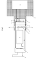
- Figs. 1 and 2 the shaft 1 of a lock cylinder is shown.
- the shaft is provided with a lock tappet 3 on the one end and a knob 2 on the opposite end.
- the lock tappet 3 is firmly connected to the shaft 1 so that rotation of the lock tappet 3 is realized.
- the knob 2 serves for turning the shaft 1 in the housing (not shown) of the lock cylinder.
- the knob 2 can freely rotate on the shaft 1 or it may engage and rotate the shaft 1.
- There are fixing means provided which hold the knob 2 on the shaft 1 in the axial direction.
- the lock cylinder is further provided with an access control unit 8 which generates an authorization signal after receiving an access signal from a key or key-card.
- the access signal may be transmitted via wireless communication.
- an electric motor drive 7 arranged in a recess of the shaft 1 drives a locking pin 5 into a recess or hole 6 in the socket 4 of the knob 2.
- the electric motor drive 7 turns an eccentric 13 which moves a rod 14 connected to the locking pin 5.
- the locking pin 5 is movable in the shaft 1 in the radial direction between a recessed position and an extended position.
- the rod 14 is movable against the force of a spring 16 within a sleeve 15 of the locking pin 5. With this arrangement it is possible to move the rod 14 into its extended position, the operating or engaging position, even if the locking pin 5 is not in an aligned position or in an engaged position with the recess or hole 6 of the socket 4 of the knob 2. If the knob 2 is turned until the recess or hole 6 is opposite to or aligned with the locking pin 5, as it is shown in Fig. 2, the locking pin 5 is forced into the recess or hole 6 by the expansion of the spring 16. As shown in Fig.
- a sensor 17 may be provided to detect the position of the locking pin 5.
- the sensor 17 may be a hall sensor or any other suitable type of sensor capable of detecting the presence or lack thereof of the sleeve 15 in one of the holes 6. The sensor 17 then relays the presence information to a control unit 11 and access control unit 8.
- the authorization signal for operating the electric motor drive 7 is transmitted to the control unit 11 and access control unit 8 by a slip ring arrangement.
- three contact rings 9 of increasing diameter are placed on the front face of the shaft 1.
- the pins 10 are in electric contact with the contact rings 9. Wireless transmission of the authorization signal between the control unit 11 and the access control unit 8 may also be possible.
- the knob 2 with the access control unit 8 can be easily changed. It is only required to provide a knob with the desired access control technique which can be mounted on the free end of the shaft 1.
- a drill plate 12 may be provided in front of the locking pin 5 within the shaft 1 in order to prevent drilling and tampering of the locking means.
- the housing of the lock cylinder preferably has a size such that the recesses or holes 6 are covered.
- a protection shield (not shown) may be provided which extends to the knob 5 such that the socket 4 cannot be reached.
- the access control unit 8 receives the access signal. After detecting the authorized access signal an authorization signal is generated by the access control unit 8 and is transmitted to the control unit 11. The control unit 11 generates an electric signal upon which the electric motor drive 7 turns the eccentric 13. The eccentric 13 extends the rod 14 radially outwards. If the sleeve 15 of the locking pin 5 is aligned with a locking hole 6 of the socket 4 of the knob, the locking pin 5 engages the hole 6. The shaft can be turned by the knob.
- the rod 14 is moved into the sleeve 15 and compresses the spring 16.
- the sleeve is now under compression with the effect that, upon turning the knob 5 until a locking hole 6 of the socket 4 of the knob 5 is opposite to the sleeve 15, the sleeve will be forced into the recess or hole 6. Then, the shaft 1 can be turned by the knob 5.
- the lock tappet 3 of the lock can be turned for opening or closing the lock. It may be provided that, after a predetermined time or after the operation of the lock, a signal is generated for moving the eccentric 13 and the rod 14 to its recessed or radially withdrawn position.
Landscapes
- Physics & Mathematics (AREA)
- Electromagnetism (AREA)
- Lock And Its Accessories (AREA)
Abstract
Description
- The invention concerns an electromechanical lock cylinder comprising a housing in which a rotatable shaft is mounted which is connected to a lock tappet to operate a locking mechanism, and at least one knob for turning said shaft.
- Such electromechanical lock cylinders are well known in the prior art.
Document EP 1 065 335 A1 discloses a lock cylinder which is operated by a knob on the one side and by a key on the other side. The knob is firmly connected to a shaft. On the opposite side of the cylinder housing there is provided a slot for inserting the key. The lock cylinder is further provided with electric coupling means which couple the lock core with the lock tappet upon receiving an authorization signal from an access control unit which reads an access signal from the key. After authorization has been detected and the coupling means has coupled the lock core with the lock tappet, the lock can be opened by the key. The knob is firmly connected to the lock tappet and the lock mechanism can be opened or closed. - Document
WO 2005/001224 A1 discloses a knob operated lock cylinder where the lock tappet of which is freely rotatably mounted on the knob shaft. A locking pin is forced into a hole of a ring by an electric motor drive in which the ring carries the lock tappet. The access control unit is located in the knob which is firmly connected to the shaft. - In some situations it is not possible to arrange the coupling means between the locking tappet and the shaft or the lock core. It is an object of the invention to provide an electromechanical lock cylinder which can be used in many different kinds of doors or lock casings.
- The object is solved by the invention in that, in a rest position, the knob is freely turnably arranged on said shaft and that electromechanically driven locking means are provided in said shaft or in said knob for, in an operating position, coupling the shaft with the knob. With that, the rotating parts can be easily adapted to the locking mechanism.
- According to a preferred embodiment of the invention the locking means comprise at least one locking pin which is movable between a rest position in which it is not engaged with said knob or shaft and an operating position in which it is engaged with said knob or shaft. The locking pin may be moved by an eccentric which is driven by an electric motor drive. Such an eccentric with an electric motor drive can be placed in the shaft without any problems.
- In an alternative embodiment of the invention the locking pin is moved by an electromechanical drive. Such an electromechanical device requires only little built-in space and is controllable in an easy manner.
- Preferably, the locking pin is engageable with said shaft or knob in more than one position of the knob relative to the shaft. Then, the knob must only be turned until the next engaging position is reached for allowing the locking pin to become engaged.
- Further, it can be provided that the locking pin is moved and held in the operating position under tension. Then, an engagement of the knob and the shaft is possible even if the locking pin is not in the position to engage the corresponding recess or hole within the shaft or knob. The knob must only be turned until the next engaging position is reached. Then, the locking pin is moved into the recess or hole due to the tension. With such an arrangement it is only required to generate one single authorization signal upon which the locking pin is moved into a position in which it is able to connect the shaft to the knob. If the knob is turned accordingly, the locking pin will engage the corresponding locking hole. Upon a release signal, the locking pin will be moved in a position in which no engagement is possible.
- It is preferable that, in the axial direction of the shaft, the knob is fixed on said shaft. This has the advantage that the knob cannot be pulled off the shaft. The lock can only be operated by said knob and any misuse is prevented.
- The lock cylinder can be a half-cylinder comprising one knob on the one end and the locking tappet on the opposite end of the housing. It is also possible that the lock cylinder is a double-sided cylinder comprising on its both sides a knob.
- Within the lock cylinder, the arrangement of the driving means and the access control unit means is arbitrary. However, it is preferred that the driving means are arranged in said shaft and an access control unit for generating an access signal upon which the driving means will couple the knob with the shaft is arranged in said knob. With that, the mechanical locking parts may be located on or in the shaft only and the access control unit means may be arranged in the knob. Then, it is only required to change the knob in order to install other access control techniques. It is also possible that the driving means and locking means are arranged in the knob and an access control unit for generating an access signal upon which the driving means will couple the knob with the shaft is arranged in said shaft.
- The invention is described below in detail with the help of the attached schematic drawings wherein
- Fig. 1
- is a longitudinal sectional view of the lock cylinder of the invention, and
- Fig. 2
- is a cross-sectional view along line A-A in Fig. 1.
- In Figs. 1 and 2, the
shaft 1 of a lock cylinder is shown. The shaft is provided with a lock tappet 3 on the one end and aknob 2 on the opposite end. Thelock tappet 3 is firmly connected to theshaft 1 so that rotation of thelock tappet 3 is realized. Theknob 2 serves for turning theshaft 1 in the housing (not shown) of the lock cylinder. Theknob 2 can freely rotate on theshaft 1 or it may engage and rotate theshaft 1. There are fixing means provided which hold theknob 2 on theshaft 1 in the axial direction. - The lock cylinder is further provided with an
access control unit 8 which generates an authorization signal after receiving an access signal from a key or key-card. The access signal may be transmitted via wireless communication. Upon generation of the authorization signal an electric motor drive 7 arranged in a recess of theshaft 1 drives a locking pin 5 into a recess orhole 6 in thesocket 4 of theknob 2. The electric motor drive 7 turns an eccentric 13 which moves arod 14 connected to the locking pin 5. With this arrangement a connection between theknob 2 andshaft 1 is provided. Thelock tappet 3 can then be turned by theknob 2. - The locking pin 5 is movable in the
shaft 1 in the radial direction between a recessed position and an extended position. Therod 14 is movable against the force of aspring 16 within asleeve 15 of the locking pin 5. With this arrangement it is possible to move therod 14 into its extended position, the operating or engaging position, even if the locking pin 5 is not in an aligned position or in an engaged position with the recess orhole 6 of thesocket 4 of theknob 2. If theknob 2 is turned until the recess orhole 6 is opposite to or aligned with the locking pin 5, as it is shown in Fig. 2, the locking pin 5 is forced into the recess orhole 6 by the expansion of thespring 16. As shown in Fig. 3, there may be provided a plurality of receses or holes 6 in thesocket 4 of theknob 2. In the example of Fig. 2, an engaging position is provided each 90° along the periphery of thesocket 4. Asensor 17 may be provided to detect the position of the locking pin 5. Thesensor 17 may be a hall sensor or any other suitable type of sensor capable of detecting the presence or lack thereof of thesleeve 15 in one of theholes 6. Thesensor 17 then relays the presence information to acontrol unit 11 andaccess control unit 8. - The authorization signal for operating the electric motor drive 7 is transmitted to the
control unit 11 andaccess control unit 8 by a slip ring arrangement. In the embodiment of Fig. 2, threecontact rings 9 of increasing diameter are placed on the front face of theshaft 1. There are corresponding contact pins 10 provided on the inner side of the knob 5 facing the front face of theshaft 1. Thepins 10 are in electric contact with the contact rings 9. Wireless transmission of the authorization signal between thecontrol unit 11 and theaccess control unit 8 may also be possible. - The
knob 2 with theaccess control unit 8 can be easily changed. It is only required to provide a knob with the desired access control technique which can be mounted on the free end of theshaft 1. For further security adrill plate 12 may be provided in front of the locking pin 5 within theshaft 1 in order to prevent drilling and tampering of the locking means. The housing of the lock cylinder preferably has a size such that the recesses orholes 6 are covered. A protection shield (not shown) may be provided which extends to the knob 5 such that thesocket 4 cannot be reached. - For operating the lock a key or key-card is held in front of the
knob 2. Theaccess control unit 8 receives the access signal. After detecting the authorized access signal an authorization signal is generated by theaccess control unit 8 and is transmitted to thecontrol unit 11. Thecontrol unit 11 generates an electric signal upon which the electric motor drive 7 turns the eccentric 13. The eccentric 13 extends therod 14 radially outwards. If thesleeve 15 of the locking pin 5 is aligned with alocking hole 6 of thesocket 4 of the knob, the locking pin 5 engages thehole 6. The shaft can be turned by the knob. - If the
sleeve 15 is not in an engaging position aligned with a recess orhole 6, therod 14 is moved into thesleeve 15 and compresses thespring 16. The sleeve is now under compression with the effect that, upon turning the knob 5 until alocking hole 6 of thesocket 4 of the knob 5 is opposite to thesleeve 15, the sleeve will be forced into the recess orhole 6. Then, theshaft 1 can be turned by the knob 5. - After this engagement the
lock tappet 3 of the lock can be turned for opening or closing the lock. It may be provided that, after a predetermined time or after the operation of the lock, a signal is generated for moving the eccentric 13 and therod 14 to its recessed or radially withdrawn position.
Claims (10)
- Electromechanical lock cylinder comprising:a housing in which a rotatable shaft is mounted that is connected to a lock tappet to operate a locking mechanism; andat least one knob for turning said shaft, characterized in that, in a rest position, the knob is freely turnably arranged on said shaft and that electromechanically driven locking means are provided in said shaft or in said knob for, in an operating position, coupling the shaft with the knob.
- Electromechanical lock cylinder according to claim 1, characterized in that the locking means comprise at least one locking pin which is movable between a rest position in which it is not engaged with said knob or shaft and an operating position in which it is engaged with said knob or shaft.
- Electromechanical lock cylinder according to claim 2, characterized in that the locking pin is moved by an eccentric which is driven by an electric motor drive.
- Electromechanical lock cylinder according to claim 2, characterized in that the locking pin is moved by an electromechanical drive.
- Electromechanical lock cylinder according to claim 2, characterized in that the locking pin is engageable with said shaft or knob in more than one position of the knob relative to the shaft.
- Electromechanical lock cylinder according to claim 1, characterized in that the knob is fixed on said shaft in an axial direction of the shaft.
- Electromechanical lock cylinder according to claim 1, characterized in that said lock cylinder includes a half-cylinder comprising one knob on the one end and the locking tappet on the opposite end of the housing.
- Electromechanical lock cylinder according to claim 1, characterized in that said lock cylinder includes a double-sided cylinder comprising on both sides a knob.
- Electromechanical lock cylinder according to claim 1, characterized in that the driving means and locking means are arranged in said shaft and an access control unit for generating an access signal upon which the driving means will couple the knob with the shaft is arranged in said knob.
- Electromechanical lock cylinder according to claim 1, characterized in that the driving means and locking means are arranged in said knob and an access control unit for generating an access signal upon which the driving means will couple the knob with the shaft is arranged in said shaft.
Applications Claiming Priority (1)
| Application Number | Priority Date | Filing Date | Title |
|---|---|---|---|
| US11/534,509 US20080072636A1 (en) | 2006-09-22 | 2006-09-22 | Knob operated electromechanical lock cylinder |
Publications (2)
| Publication Number | Publication Date |
|---|---|
| EP1903169A2 true EP1903169A2 (en) | 2008-03-26 |
| EP1903169A3 EP1903169A3 (en) | 2008-10-15 |
Family
ID=38823563
Family Applications (1)
| Application Number | Title | Priority Date | Filing Date |
|---|---|---|---|
| EP20070116833 Withdrawn EP1903169A3 (en) | 2006-09-22 | 2007-09-20 | Knob operated electromechanical lock cylinder |
Country Status (4)
| Country | Link |
|---|---|
| US (1) | US20080072636A1 (en) |
| EP (1) | EP1903169A3 (en) |
| AU (1) | AU2007216769A1 (en) |
| CA (1) | CA2603617A1 (en) |
Cited By (5)
| Publication number | Priority date | Publication date | Assignee | Title |
|---|---|---|---|---|
| ES2331864A1 (en) * | 2008-07-15 | 2010-01-18 | Salto Systems, S.L. | Electromechanical cylinder for a lock |
| EP2453085A3 (en) * | 2010-11-10 | 2014-10-22 | BKS GmbH | Locking device |
| WO2020205863A1 (en) | 2019-04-05 | 2020-10-08 | Dormakaba Usa Inc. | Electro-mechanical lock core with a cam member tailpiece |
| US11421447B2 (en) * | 2015-02-25 | 2022-08-23 | Triteq Lock And Security, Llc | Lock |
| US11952801B2 (en) | 2019-04-05 | 2024-04-09 | dormakaba USA, Inc | Electro-mechanical lock core with a cam member tailpiece |
Families Citing this family (12)
| Publication number | Priority date | Publication date | Assignee | Title |
|---|---|---|---|---|
| EP1739631B1 (en) * | 2005-06-24 | 2012-10-24 | Assa Abloy Ab | Modular cylinder lock |
| DE102008018906B4 (en) * | 2008-04-14 | 2011-06-30 | ASTRA Gesellschaft für Asset Management mbH & Co. KG, 30890 | Lock cylinder arrangement |
| US8474290B2 (en) * | 2009-12-03 | 2013-07-02 | Pioptima, Inc. | Locking handle and power module assembly |
| US8978428B2 (en) * | 2011-09-08 | 2015-03-17 | Medeco Security Locks, Inc. | Apparatus for automatically returning a lock to a desired orientation |
| AR109978A1 (en) | 2016-10-19 | 2019-02-13 | Best Access Solutions Inc | ELECTROMECHANICAL LOCK CORE |
| CN107060501A (en) * | 2017-06-21 | 2017-08-18 | 北京洛克欧乐科技股份有限公司 | Knob electronic lock |
| EP3679207B1 (en) | 2017-09-08 | 2022-08-03 | Dormakaba USA Inc. | Electro-mechanical lock core |
| AU2019252796B2 (en) | 2018-04-13 | 2022-04-28 | Dormakaba Usa Inc. | Electro-mechanical lock core |
| US11466473B2 (en) | 2018-04-13 | 2022-10-11 | Dormakaba Usa Inc | Electro-mechanical lock core |
| US11655653B1 (en) | 2022-04-15 | 2023-05-23 | Digilock Asia Ltd. | Electronically operated lock cylinder |
| US12152409B2 (en) | 2022-04-15 | 2024-11-26 | Security People, Inc. | Electronic mortise lock cylinder |
| DE102023136459A1 (en) * | 2023-12-22 | 2025-06-26 | ASTRA Gesellschaft für Asset Management mbH & Co. KG | Electric locking unit |
Family Cites Families (37)
| Publication number | Priority date | Publication date | Assignee | Title |
|---|---|---|---|---|
| US4073527A (en) * | 1977-01-12 | 1978-02-14 | Schlage Lock Company | Electrically controlled door lock |
| FR2591265B1 (en) * | 1985-12-11 | 1988-03-25 | Llort Oscar | ELECTRICALLY CONTROLLED ARM LOCK USING AN ELECTROMAGNET |
| CH671800A5 (en) * | 1987-02-09 | 1989-09-29 | Berchtold Ag | |
| US4856310A (en) * | 1987-04-29 | 1989-08-15 | Raoul Parienti | Electronic lock |
| US4810014A (en) * | 1987-08-20 | 1989-03-07 | Mcgourty Thomas K | Motor driven lock control |
| US4901545A (en) * | 1987-12-28 | 1990-02-20 | Rising Star Technologies (A Partnership) | Self-contained electromechanical locking device |
| DE3902992C1 (en) * | 1989-02-02 | 1990-03-29 | Dom-Sicherheitstechnik Gmbh & Co Kg, 5040 Bruehl, De | |
| US5027629A (en) * | 1990-01-22 | 1991-07-02 | Liu Yin Chic | Control mechanism of electronic lock |
| SE505493C2 (en) * | 1992-03-26 | 1997-09-08 | Assa Ab | Cylinder |
| US5848541A (en) * | 1994-03-30 | 1998-12-15 | Dallas Semiconductor Corporation | Electrical/mechanical access control systems |
| GB9417748D0 (en) * | 1994-09-03 | 1994-10-19 | Yale Security Prod Ltd | Electrically operable cylinder lock |
| ES2106668B1 (en) * | 1994-11-18 | 1998-06-01 | Azbe B Zubia S A | IMPROVEMENTS INTRODUCED IN ELECTRONIC-MECHANICAL SEALING CYLINDERS. |
| DE19517728C2 (en) * | 1995-05-15 | 1998-12-03 | Keso Gmbh | Locking device |
| US6564601B2 (en) * | 1995-09-29 | 2003-05-20 | Hyatt Jr Richard G | Electromechanical cylinder plug |
| DE29703559U1 (en) * | 1996-03-27 | 1997-04-30 | Hainzlmaier, Hermann, 85290 Geisenfeld | Door lock |
| AT407175B (en) * | 1997-04-25 | 2001-01-25 | Roto Frank Eisenwaren | CONTROL DEVICE |
| DE19754923C1 (en) * | 1997-12-10 | 1999-04-01 | Sesam Elektronische Sicherheit | Door mounting for closing-locking mechanism of door with latching facility |
| US6374653B1 (en) * | 1997-12-22 | 2002-04-23 | Security People, Inc. | Mechanical/electronic lock and key therefor |
| US6826935B2 (en) * | 1997-12-22 | 2004-12-07 | Security People, Inc. | Mechanical/electronic lock and key therefor |
| US6442986B1 (en) * | 1998-04-07 | 2002-09-03 | Best Lock Corporation | Electronic token and lock core |
| FR2779168B1 (en) * | 1998-05-27 | 2001-01-26 | Euronetics France | ELECTRONIC LOCK WITH MECHANICAL CLUTCH |
| DE19824713A1 (en) * | 1998-06-03 | 1999-12-16 | Dom Sicherheitstechnik | Door lock cylinder with internal rotating members |
| AUPP400798A0 (en) * | 1998-06-11 | 1998-07-02 | Lockwood Security Products Pty Limited | Electrically controlled lock |
| DE19834691A1 (en) * | 1998-07-31 | 2000-02-03 | Wilke Heinrich Hewi Gmbh | Locking system |
| DE19854879C1 (en) * | 1998-11-27 | 2000-08-03 | Ulf Klenk | Remotely controllable closure device for doors with integral antenna for radio operation formed by door fitting(s) or operating element electrically connected to integrated electronics |
| US6286347B1 (en) * | 1999-08-09 | 2001-09-11 | Harrow Products, Inc. | Clutch mechanism with moveable injector retainer wall for door lock system |
| US6523377B1 (en) * | 1999-09-21 | 2003-02-25 | Berchtold Ag | Blocking device for a cylinder lock |
| US6578396B2 (en) * | 2000-03-29 | 2003-06-17 | Medeco Security Locks, Inc. | Removable cylindrical lock core |
| ES2191522B1 (en) * | 2000-12-11 | 2004-11-01 | Talleres De Escoriaza, S.A. | CLUTCH DEVICE FOR LOCKER. |
| JP3553025B2 (en) * | 2001-03-30 | 2004-08-11 | 株式会社加貫ローラ製作所 | Cleaning sheet for printing press cylinder and method of manufacturing the same |
| JP2003135808A (en) * | 2001-11-06 | 2003-05-13 | Kpe Inc | Locking device, key, and locking method |
| US20030200778A1 (en) * | 2002-04-24 | 2003-10-30 | Intellikey Corporation | Biometric electronic key with build in proximity detector and infrared communication as dual verification |
| DE10230344B3 (en) * | 2002-07-03 | 2004-01-22 | Dom-Sicherheitstechnik Gmbh & Co. Kg | Tamper-proof electromagnet assembly, electronic lock cylinder and method for preventing manipulation of a solenoid assembly |
| GB2390394B (en) * | 2002-07-03 | 2004-05-26 | Shyang Feng Electric & Machine | Improved electronic lock |
| US6865916B2 (en) * | 2002-08-28 | 2005-03-15 | Ilan Goldman | Door cylinder lock |
| US6725693B2 (en) * | 2002-08-30 | 2004-04-27 | Jer Ming Yu | Door lock with a clutch having a cam-styled axle sleeve |
| DE10328297A1 (en) * | 2003-06-23 | 2005-01-20 | Buga Technologies Gmbh | Electromechanical lock cylinder |
-
2006
- 2006-09-22 US US11/534,509 patent/US20080072636A1/en not_active Abandoned
-
2007
- 2007-09-13 AU AU2007216769A patent/AU2007216769A1/en not_active Abandoned
- 2007-09-20 EP EP20070116833 patent/EP1903169A3/en not_active Withdrawn
- 2007-09-21 CA CA 2603617 patent/CA2603617A1/en not_active Abandoned
Cited By (11)
| Publication number | Priority date | Publication date | Assignee | Title |
|---|---|---|---|---|
| ES2331864A1 (en) * | 2008-07-15 | 2010-01-18 | Salto Systems, S.L. | Electromechanical cylinder for a lock |
| WO2010007196A1 (en) * | 2008-07-15 | 2010-01-21 | Salto Systems, S.L. | Electromechanical cylinder for a lock |
| ES2331864B1 (en) * | 2008-07-15 | 2010-10-28 | Salto Systems, S.L. | ELECTROMECHANICAL CYLINDER FOR LOCK. |
| EP2453085A3 (en) * | 2010-11-10 | 2014-10-22 | BKS GmbH | Locking device |
| EP2453085B1 (en) | 2010-11-10 | 2017-12-06 | BKS GmbH | Locking device |
| DE102010043705B4 (en) | 2010-11-10 | 2024-02-08 | Bks Gmbh | Locking device |
| US11421447B2 (en) * | 2015-02-25 | 2022-08-23 | Triteq Lock And Security, Llc | Lock |
| US20230125284A1 (en) * | 2015-02-25 | 2023-04-27 | Triteq Lock And Security, Llc | Lock |
| WO2020205863A1 (en) | 2019-04-05 | 2020-10-08 | Dormakaba Usa Inc. | Electro-mechanical lock core with a cam member tailpiece |
| EP3927919A4 (en) * | 2019-04-05 | 2022-11-23 | Dormakaba USA Inc. | ELECTROMECHANICAL LOCK CORE WITH CAM ELEMENT BOLT TAIL |
| US11952801B2 (en) | 2019-04-05 | 2024-04-09 | dormakaba USA, Inc | Electro-mechanical lock core with a cam member tailpiece |
Also Published As
| Publication number | Publication date |
|---|---|
| AU2007216769A1 (en) | 2008-04-10 |
| CA2603617A1 (en) | 2008-03-22 |
| US20080072636A1 (en) | 2008-03-27 |
| EP1903169A3 (en) | 2008-10-15 |
Similar Documents
| Publication | Publication Date | Title |
|---|---|---|
| CA2603617A1 (en) | Knob operated electromechanical lock cylinder | |
| US7874190B2 (en) | Electromechanical lock cylinder | |
| US7845202B2 (en) | Interchangeable electromechanical lock core | |
| US11459794B2 (en) | Door lock assembly | |
| KR100989001B1 (en) | Door cylinder lock | |
| CA2551000C (en) | Modular electromechanical locking cylinder | |
| HUP0002410A2 (en) | Locking device | |
| JP2003525364A (en) | Locking device for cylinder lock | |
| CN104487642A (en) | Locking device comprising a deactivation mechanism | |
| EP4038583B1 (en) | Electromechanical lock assembly | |
| WO2015065944A1 (en) | Electromechanical lock cylinder | |
| JP2012180739A (en) | Closing device | |
| FI83904B (en) | ELEKTRISKT ELLER ELEKTRONISKT DOERRLAOS, SAERSKILT STICKLAOS. | |
| AU2022402347B2 (en) | Blocking device for a closure element or a switching element | |
| EP4038251B1 (en) | Electromechanical lock assembly with annular element, blocking and retaining devices | |
| KR101513928B1 (en) | Module for Locking Door in Electrical Operation and System Having The Same | |
| EP4448895B1 (en) | Lock device and lock system | |
| KR200363382Y1 (en) | A Deadbolt Operating Device | |
| HK1117884B (en) | Closing device |
Legal Events
| Date | Code | Title | Description |
|---|---|---|---|
| PUAI | Public reference made under article 153(3) epc to a published international application that has entered the european phase |
Free format text: ORIGINAL CODE: 0009012 |
|
| AK | Designated contracting states |
Kind code of ref document: A2 Designated state(s): AT BE BG CH CY CZ DE DK EE ES FI FR GB GR HU IE IS IT LI LT LU LV MC MT NL PL PT RO SE SI SK TR |
|
| AX | Request for extension of the european patent |
Extension state: AL BA HR MK YU |
|
| RAP1 | Party data changed (applicant data changed or rights of an application transferred) |
Owner name: ASSA ABLOY AB |
|
| PUAL | Search report despatched |
Free format text: ORIGINAL CODE: 0009013 |
|
| AK | Designated contracting states |
Kind code of ref document: A3 Designated state(s): AT BE BG CH CY CZ DE DK EE ES FI FR GB GR HU IE IS IT LI LT LU LV MC MT NL PL PT RO SE SI SK TR |
|
| AX | Request for extension of the european patent |
Extension state: AL BA HR MK RS |
|
| 17P | Request for examination filed |
Effective date: 20090415 |
|
| AKX | Designation fees paid |
Designated state(s): AT BE BG CH CY CZ DE DK EE ES FI FR GB GR HU IE IS IT LI LT LU LV MC MT NL PL PT RO SE SI SK TR |
|
| 17Q | First examination report despatched |
Effective date: 20090701 |
|
| STAA | Information on the status of an ep patent application or granted ep patent |
Free format text: STATUS: THE APPLICATION IS DEEMED TO BE WITHDRAWN |
|
| 18D | Application deemed to be withdrawn |
Effective date: 20091112 |