EP1902872A1 - Suspension device for vehicle - Google Patents
Suspension device for vehicle Download PDFInfo
- Publication number
- EP1902872A1 EP1902872A1 EP06757235A EP06757235A EP1902872A1 EP 1902872 A1 EP1902872 A1 EP 1902872A1 EP 06757235 A EP06757235 A EP 06757235A EP 06757235 A EP06757235 A EP 06757235A EP 1902872 A1 EP1902872 A1 EP 1902872A1
- Authority
- EP
- European Patent Office
- Prior art keywords
- wheel
- contact point
- camber angle
- virtual link
- rotation
- Prior art date
- Legal status (The legal status is an assumption and is not a legal conclusion. Google has not performed a legal analysis and makes no representation as to the accuracy of the status listed.)
- Ceased
Links
Images


Classifications
-
- B—PERFORMING OPERATIONS; TRANSPORTING
- B60—VEHICLES IN GENERAL
- B60G—VEHICLE SUSPENSION ARRANGEMENTS
- B60G3/00—Resilient suspensions for a single wheel
- B60G3/18—Resilient suspensions for a single wheel with two or more pivoted arms, e.g. parallelogram
- B60G3/20—Resilient suspensions for a single wheel with two or more pivoted arms, e.g. parallelogram all arms being rigid
- B60G3/26—Means for maintaining substantially-constant wheel camber during suspension movement ; Means for controlling the variation of the wheel position during suspension movement
-
- B—PERFORMING OPERATIONS; TRANSPORTING
- B60—VEHICLES IN GENERAL
- B60G—VEHICLE SUSPENSION ARRANGEMENTS
- B60G7/00—Pivoted suspension arms; Accessories thereof
- B60G7/008—Attaching arms to unsprung part of vehicle
-
- B—PERFORMING OPERATIONS; TRANSPORTING
- B60—VEHICLES IN GENERAL
- B60G—VEHICLE SUSPENSION ARRANGEMENTS
- B60G2200/00—Indexing codes relating to suspension types
- B60G2200/10—Independent suspensions
- B60G2200/14—Independent suspensions with lateral arms
- B60G2200/144—Independent suspensions with lateral arms with two lateral arms forming a parallelogram
-
- B—PERFORMING OPERATIONS; TRANSPORTING
- B60—VEHICLES IN GENERAL
- B60G—VEHICLE SUSPENSION ARRANGEMENTS
- B60G2200/00—Indexing codes relating to suspension types
- B60G2200/10—Independent suspensions
- B60G2200/18—Multilink suspensions, e.g. elastokinematic arrangements
-
- B—PERFORMING OPERATIONS; TRANSPORTING
- B60—VEHICLES IN GENERAL
- B60G—VEHICLE SUSPENSION ARRANGEMENTS
- B60G2200/00—Indexing codes relating to suspension types
- B60G2200/40—Indexing codes relating to the wheels in the suspensions
- B60G2200/46—Indexing codes relating to the wheels in the suspensions camber angle
-
- B—PERFORMING OPERATIONS; TRANSPORTING
- B60—VEHICLES IN GENERAL
- B60G—VEHICLE SUSPENSION ARRANGEMENTS
- B60G2204/00—Indexing codes related to suspensions per se or to auxiliary parts
- B60G2204/10—Mounting of suspension elements
- B60G2204/14—Mounting of suspension arms
- B60G2204/148—Mounting of suspension arms on the unsprung part of the vehicle, e.g. wheel knuckle or rigid axle
-
- B—PERFORMING OPERATIONS; TRANSPORTING
- B60—VEHICLES IN GENERAL
- B60G—VEHICLE SUSPENSION ARRANGEMENTS
- B60G2204/00—Indexing codes related to suspensions per se or to auxiliary parts
- B60G2204/40—Auxiliary suspension parts; Adjustment of suspensions
- B60G2204/422—Links for mounting suspension elements
Definitions
- the conventional suspension device capable of varying the camber angle of a wheel independently of the up-and-down movement of the wheel is a suspension structure having a layout newly provided with a link so as to set an instantaneous rotation center of movement of a wheel in the camber angle direction at a desired position.
- the instantaneous rotation center of movement in the camber angle direction is set at a position located away from the ground surface below the ground surface, the wheel moves in the camber angle direction about the instantaneous rotation of movement in the camber angle direction, and therefore the tire ground contact point moves laterally with the generation of the camber angle.
- This link 6 is shaped like an inverted T.
- the lower end portions of links 4 and 5 are connected, respectively, with both ends of a horizontal portion 6a of the link 6, rotatably through rotational members 4b and 5b.
- the horizontal portion 6a of link 6 extends substantially in a horizontal direction.
- Links 4 and 5 are arranged so that an intersection point of extensions of axes of links 4 and 5 is located below a ground surface.
- a spring member 10 is connected rotatably between link 8 and vehicle body 1.
- Spring member 10 extends substantially in the up-and-down direction, and spring member 10 can support the weight of the vehicle body.
- Spring member 10 corresponds to a shock absorber or the like.
- link 6 is supported so that link 6 can move in the up-and-down direction relative to vehicle body 1, in response to input of a force in the up-and-down direction from the road surface.
- rotation support member 3 is supported so that rotation support member 3 can move in a lateral direction relative to link 6 in response to input of a force in the lateral direction from the road surface.
- Wheel load variation ⁇ W can be expressed as a function of lateral force Fy acting on the tire, as a variable, as expressed by equation (9).
- equation (9) the relationship exists between lateral force Fy acting on the tire and wheel load variation ⁇ W in a vehicle driving state. Therefore, from the position of the center of gravity of the vehicle body, the roll stiffness, the wheel load distribution, and the height of the roll center, it is possible to set the instantaneous rotation center B with respect to the instantaneous rotation center A so as to make the camber angle and the lateral displacement of the tire ground contact point equal to desired values in a given vehicle driving state.
- the suspension system can improve the vehicle response against the addition of the camber angle.
- the bushes are used as the elastic member.
- the present invention is not limited to this. It is possible to employ a member, such as a spring member, which can deform elastically.
- the third embodiment is identical to the first embodiment except for the method for setting the instantaneous rotation centers A and B. Accordingly, the same parts are given the same reference numerals and detailed explanation on the same parts is omitted.
- the instantaneous rotation center B is set with respect to instantaneous rotation center A so that a lateral movement amount ⁇ yl1u of an upper portion of wheel 2 in the direction to the inner side of the turn caused by the inclination of first virtual link 11 in the camber angle direction becomes substantially equal to the lateral movement amount ⁇ yl2 of the tire ground contact point by second virtual link 12.
Landscapes
- Engineering & Computer Science (AREA)
- Mechanical Engineering (AREA)
- Vehicle Body Suspensions (AREA)
Abstract
Description
- The present invention relates to vehicle suspension device or apparatus capable of controlling the posture of a vehicle body, and more specifically to a vehicle suspension device or apparatus arranged to control a camber angle by utilizing a tire lateral force acting on a tire.
- As a suspension device to vary a camber angle by utilizing a tire lateral force, there has been proposed a suspension device, as recited in a
Patent Document 1, capable of varying the camber angle independently of an up-down movement of a wheel. This suspension device is arranged so that an instantaneous rotation center of movement of a wheel in a camber angle direction is set at a position below a ground surface, and that, in the case of the application of a tire lateral force, this suspension device can provide a negative camber to an outer wheel on the outer side of a turn and a positive camber to an inner wheel on the inner side of the turn. When the instantaneous rotation center of movement in the camber angle direction is set at a position above the ground surface near the ground surface, the suspension device is arranged to control the camber angle with actuators or the like.
Patent Document 1: PublishedJapanese translation of PCT Application Publication No. 2003-528771 - The conventional suspension device capable of varying the camber angle of a wheel independently of the up-and-down movement of the wheel is a suspension structure having a layout newly provided with a link so as to set an instantaneous rotation center of movement of a wheel in the camber angle direction at a desired position.
When the instantaneous rotation center of movement in the camber angle direction is set at a position located away from the ground surface below the ground surface, the wheel moves in the camber angle direction about the instantaneous rotation of movement in the camber angle direction, and therefore the tire ground contact point moves laterally with the generation of the camber angle. - That is, when a tire lateral force acts in a state of steady driving of the vehicle, a wheel on the outer side of a turn inclines to a negative camber direction about the instantaneous rotation center of movement in the camber angle direction located away from the ground surface and a wheel on the inner side of the turn inclines to a positive camber direction about the instantaneous rotation center of movement in the camber angle direction located away from the ground surface. Therefore, the tire ground contact point moves instantaneously to the inner side of the turn at a speed. By this movement, a tire lateral force is produced in a direction to impede the turn, that is, the direction toward the outer side of the turn, and the response of the vehicle is deteriorated by the addition of the camber angle.
- In order to reduce this lateral displacement of the tire ground contact point to zero, it is possible to set the instantaneous rotation center of movement in the camber angle direction at a position near the ground surface. The setting of the instantaneous rotation center of movement in the camber angle direction near the ground surface decreases the camber angle toward zero, and hence impairs the effect of the camber angle.
Accordingly, in order to control the camber angle to an adequate value, and at the same time to decrease the lateral displacement of the tire ground contact point, the suspension system requires actuators for controlling the camber angle and the lateral displacement of the tire ground contact point, respectively. However, the addition of such actuators increases the cost.
Therefore, the present invention is devised in view of these problems. An object of the invention is to provide a vehicle suspension device or apparatus capable of controlling the camber angle to an adequate value by utilizing a lateral force acting on a tire without impairing the effect of variation of the camber angle. - To achieve the above-mentioned object, a vehicle suspension device or apparatus according to the present invention comprises a link mechanism replaceable equivalently by first and second virtual links. The first virtual link is a virtual link which, when a lateral force acts at a tire ground contact point, inclines a wheel in a camber angle direction with respect to a vehicle body and in a direction increasing the lateral force, independently of displacement of the wheel in an up-and-down direction. The second virtual link is a virtual link which is connected virtually and rotatably between the first virtual link and the vehicle body and which is arranged to allow the wheel to move in the up-and-down direction with respect to the vehicle body in accordance with a load variation of the wheel in the up-and-down direction. A rotation center in the camber angle direction, of the wheel with respect to the vehicle body and a rotation center in the up-and-down direction, of the wheel with respect to the vehicle body are so arranged that, in a state in which the lateral force acts at the tire ground contact point, a displacement of the tire ground contact point due to a change in the position of the first virtual link is canceled by a displacement of the tire ground contact point due to a change in the position of the second virtual link.
- The vehicle suspension device according to the present invention is constructed to include the link mechanism replaceable equivalently by the first virtual link which, when a lateral force acts at a tire ground contact point, inclines the wheel in the camber angle direction with respect to the vehicle body and in the direction increasing the lateral force, independently of displacement of the wheel in the up-and-down direction, and the second virtual link which is connected virtually and rotatably between the first virtual link and the vehicle body and which is arranged to allow the wheel to move in the up-and-down direction with respect to the vehicle body in accordance with a load variation of the wheel in the up-and-down direction. The rotation center in the camber angle direction, of the wheel with respect to the vehicle body and the rotation center in the up-and-down direction, of the wheel with respect to the vehicle body are arranged so that, in the state in which the lateral force acts at the tire ground contact point, the displacement of the tire ground contact point due to a change in the position of the first virtual link is canceled by the displacement of the tire ground contact point due to a change in the position of the second virtual link. Therefore, the vehicle suspension device can adjust the camber angle in accordance with a lateral force while causing no displacement of the tire ground contact point or decreasing the displacement of the tire ground contact point.
-
-
FIG. 1 is a schematic construction view showing a vehicle suspension device or apparatus in one example according to a first embodiment of the present invention. -
FIG. 2 is a view for illustrating a first virtual link and a second virtual link in the suspension device ofFIG. 1 . -
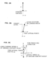
FIG. 3A is a view (R/View) in a steady state, for illustrating a force acting on a tire when a tire lateral force is applied. -
FIG. 3B is a view (R/View) for illustrating a force acting on a tire in the case of application of a tire lateral force, in a state of occurrence of a tire lateral force. -
FIG. 3C is a view (P/View) for illustrating a force acting on a tire in the case of application of a tire lateral force, to show a tire lateral slip due to a shift of a ground contact point. -
FIG. 4A is a view for illustrating operation of the first embodiment of the present invention, to show a lateral movement amount Δyl1. -
FIG. 4B is a view for illustrating operation of the first embodiment of the present invention, to show a lateral movement amount Δyl2. -
FIG. 5A is a view for illustrating a method of calculating the lateral movement amount Δyl1 of a tire ground contact point and a camber angle γ. -
FIG. 5B is a view for illustrating a method of calculating the lateral movement amount Δyl2 of the tire ground contact point. -
FIG. 6 is a view for illustrating a virtual spring Kδ. -
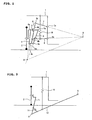
FIG. 7 is a view for illustrating the operation of the first embodiment. -
FIG. 8 is a schematic construction view showing a vehicle suspension device or apparatus in one example according to a second embodiment. -
FIG. 9 is a view for illustrating the operation of the second embodiment. -
FIG. 10 is a view for illustrating a method of calculating a lateral movement amount Δy1lu of an upper portion of a wheel. -
FIG. 11 is a view for illustrating the operation of a third embodiment. - Embodiments of the present invention will be explained hereinafter.
A first embodiment will be explained first.
FIG. 1 is a view as viewed from the rear of a vehicle body, for illustrating the principle of a suspension device or apparatus for a vehicle according to the present invention.
InFIG. 1 , a vehicle includes avehicle body 1 and awheel 2.Wheel 2 is supported rotatably by a rotation support member 3. Upper end portions oflinks 4 and 5 are rotatably connected with this rotation support member 3 throughrotational members Links 4 and 5 extend substantially in an up-and-down direction, and serve as up-and-down direction links. Lower end portions oflinks 4 and 5 are rotatably connected with a link 6 as an inverted-T-shaped link. This link 6 is shaped like an inverted T. The lower end portions oflinks 4 and 5 are connected, respectively, with both ends of ahorizontal portion 6a of the link 6, rotatably throughrotational members horizontal portion 6a of link 6 extends substantially in a horizontal direction.Links 4 and 5 are arranged so that an intersection point of extensions of axes oflinks 4 and 5 is located below a ground surface. -
Links links vehicle body 1, rotatably throughrotational members link 7 is connected, rotatably through arotational member 7b, with an end portion of avertical portion 6b of link 6. Thisvertical portion 6b of link 6 extends substantially in a vertical direction. A wheel's side end portion oflink 8 is connected, rotatably through arotational member 8b, withvertical portion 6b of link 6 at a position closer tohorizontal portion 6a.Links links - A
spring member 10 is connected rotatably betweenlink 8 andvehicle body 1.Spring member 10 extends substantially in the up-and-down direction, andspring member 10 can support the weight of the vehicle body.Spring member 10 corresponds to a shock absorber or the like.
Thus, link 6 is supported so that link 6 can move in the up-and-down direction relative tovehicle body 1, in response to input of a force in the up-and-down direction from the road surface. Moreover, the above-mentioned rotation support member 3 is supported so that rotation support member 3 can move in a lateral direction relative to link 6 in response to input of a force in the lateral direction from the road surface. In this case, an instantaneous rotation center A of movement of rotation support member 3 in the lateral direction is located at the intersection point of extensions of the axes oflinks 4 and 5. An instantaneous rotation center B of movement of link 6 in the up-and-down direction is located at the intersection point of extensions of the axes oflinks - Therefore, it is possible to consider geometrically that
wheel 2 moves in the up-and-down direction relative tovehicle body 1 by input of a force in the up-and-down direction from the road surface, and moves in a camber angle direction relative tovehicle body 1 by input of a force in the lateral direction from the road surface. Moreover, it is possible to consider that an instantaneous rotation center B ofwheel 2 in the up-and-down direction is located at the intersection point of extensions of the axes oflinks 7 and 8 (each of the extensions is a straight line connecting the connection points at both ends oflink 7 or 8); and an instantaneous rotation center A ofwheel 2 in the camber angle direction is located at the intersection point of extensions of the axes of links 4 and 5 (each of the extensions is a straight line connecting the connection points at both ends of link 4 or 5). - Rotation support member 3 supports
wheel 2 rotatably, and determines the instantaneous rotation center A in the camber angle direction together with link 4, link 5 and link 6. Therefore, it is possible to replace the rotation support member 3,links 4 and 5 and link 6 shown inFIG. 1 , equivalently with a firstvirtual link 11 connecting the instantaneous rotation center A in the camber angle direction withwheel 2, as shown inFIG. 2 . Furthermore, links 6, 7 and 8 determine the instantaneous rotation center B in the up-and-down direction, and it is possible to consider thatlinks virtual link 11. Therefore, it is possible to replacelinks virtual link 12 which is connected virtually with firstvirtual link 11 at instantaneous rotation center A in the camber angle direction, and which virtually connects the instantaneous rotation center A in the camber angle direction with the instantaneous rotation center B in the up-and-down direction. - In
FIG. 1 ,spring member 10 is connected withlink 8. However, it is optional to connectspring member 10 with any one of suspension constituent components constituting secondvirtual link 12 determining the position ofwheel 2 in the up-and-down direction.
Furthermore, inFIG. 2 , avirtual spring 14 is provided between first and secondvirtual links virtual spring 14 corresponds to a factor which can be assumed to be formed by an overturning moment caused by displacement of the tire in the camber angle direction, the friction of the suspension links constituting firstvirtual link 11, and spring components of the rotational members. Thisvirtual spring 14 is considered to be connected between first and secondvirtual links - Explanation has been directed to the suspension of a double wishbone type as shown in
FIG. 1 to illustrate the first and secondvirtual links virtual links - The following is explanation on a method for setting instantaneous rotation center A in the camber angle direction and instantaneous rotation center B in the up-and-down direction.
A camber angle control type suspension device of earlier technology is arranged to vary the camber angle when a tire lateral force is applied, as mentioned before. Therefore, this suspension device is considered to have the firstvirtual link 11 ofFIG. 2 , and arranged to determine the position of the instantaneous rotation center of firstvirtual link 11, that is, instantaneous rotation center A in the camber angle direction so as to add a camber angle with firstvirtual link 11. - This suspension device can control the camber angle in accordance with a lateral force, as mentioned above. However, in this suspension device, the addition of the camber angle causes lateral movement of a tire ground contact point, and accordingly the response of the vehicle is deteriorated by the addition of the camber angle. In other words, when the instantaneous rotation center A of
wheel 2 in the camber angle direction is set at a position below the ground surface, as shown inFIG. 3 , in a steady state (FIG. 3A , rear view) in which the camber angle is not controlled, thewheel 2 rotates about the instantaneous rotation center A in the camber angle direction by the application of a lateral force on the tire, as shown inFIG. 3B (rear view). Accordingly, the tire ground contact point moves instantaneously toward the inner side of a turn or turning motion of the vehicle. Thus, the tire ground contact point moves toward the inner side of the vehicle turning motion at a speed Vy. As a result, an angle αy is formed between a longitudinal speed V of the center of the tire ground contact point and a tire traveling direction, and a tire lateral force is produced in a direction impeding the turning motion (FIG. 3C , plan view). - According to the first embodiment, therefore, the suspension device (or apparatus) adjusts a lateral movement amount Δyl1 which is an amount of lateral movement of the tire ground contact point due to variation of the camber angle by first
virtual link 11, about instantaneous rotation center A in the camber angle direction, with a lateral movement amount Δyl2 which is an amount of lateral movement of the tire ground contact point caused by rotation of secondvirtual link 12 about instantaneous rotation center B in the up-and-down direction. By providing firstvirtual link 11 and secondvirtual link 12, as mentioned above, it is possible, in a passive suspension system, to set a camber angle variation ofwheel 2 and a lateral displacement of the tire ground contact point on the occurrence of a tire lateral force, independently and arbitrarily. - When, as shown in
FIG. 4A , the camber angle is varied by a tire lateral force, the firstvirtual link 11 rotates about instantaneous rotation center A in the camber angle direction, andwheel 2 rotates. Therefore, the tire ground contact point moves laterally by the amount Δyl1. On the other hand, the wheel load varies in association with the rotation of firstvirtual link 11 by the tire lateral force, and secondvirtual link 12 determining the position of the vehicle body in the up-and-down direction is rotated about instantaneous rotation center B in the up-and-down direction, in accordance with the wheel load variation. As a result, the tire ground contact point is moved laterally by the amount Δyl2 in the direction cancelling the lateral movement amount Δyl1. - The lateral movement amounts Δyl1 and Δyl2 of the tire ground contact point and the camber angle γ produced by rotation of first
virtual link 11 and secondvirtual link 12 are expressed by the following equations.


- In these equations, L1~L4 are values defined as shown in
FIG. 5 . As shown inFIG. 5A , L1 is a vertical distance from instantaneous rotation center A of the camber angle to the tire ground contact point; and L3 is an amount of movement of the tire ground contact point caused by the addition of a camber angle about instantaneous rotation center A. As shown inFIG. 5B , L2 is a horizontal distance between instantaneous rotation center A and instantaneous rotation center B in the up-and-down direction in a state before movement of secondvirtual link 12, that is the steady state; and L4 is a vertical distance between instantaneous rotation center A and instantaneous rotation center B in the steady state. - In the before-mentioned equations, Fy is a lateral force at the tire ground contact point; W is a wheel load in the steady state; ΔW (delta W) is a wheel load variation from the steady state; Kγ is a stiffness or rigidity in the camber angle direction by first
virtual link 11 such as overturning moment and bush stiffness; Kw is a virtual spring corresponding to a wheel end, provided in secondvirtual link 12; Kδ is a value corresponding to a spring formed by providing, in secondvirtual link 11 about instantaneous rotation center B, the virtual spring Kw provided in secondvirtual link 12, as a spring corresponding to the wheel end, as shown inFIG. 6 ; R is the length of second virtual link (i.e., the distance between instantaneous rotation centers A and B); β is an inclination angle of secondvirtual link 12; α is a variation of the inclination angle of secondvirtual link 12; and ΔZ is an up-down displacement of the tire ground contact point. - When a tire lateral force is inputted, the camber angle γ produced by first
virtual link 11 can be expressed by equation (2) from the balance about moment of the tire ground contact point. The quantity Kγ is a value corresponding to a spring (corresponding tovirtual spring 14 shown inFIG. 2 ) which acts, against a moment about instantaneous rotation center A, to prevent firstvirtual link 11 from producing a camber angle, an overturning moment of the tire and a repulsive force due to deformation of suspension members. - The lateral movement amount Δyl1 of the tire ground contact point produced by first
virtual link 11 with the camber angle γ produced by firstvirtual link 11 can be expressed by equation (1) from a geometrical relationship among the tire ground contact point, instantaneous rotation center A and camber angle γ.
The lateral movement amount Δyl2 of the tire ground contact point produced by secondvirtual link 12 is expressed by equation (3), and R, β and α appearing in equation (3) are expressed, respectively, by equations (4), (5) and (6). Quantity ΔZ in equation (6) is expressed by the equation (7), and determined by the wheel load of the vehicle body, the lateral force acting on the tire and the moment produced about instantaneous rotation center A by firstvirtual link 11. - Wheel load variation ΔW can be expressed as a function of lateral force Fy acting on the tire, as a variable, as expressed by equation (9). Thus, the relationship exists between lateral force Fy acting on the tire and wheel load variation ΔW in a vehicle driving state. Therefore, from the position of the center of gravity of the vehicle body, the roll stiffness, the wheel load distribution, and the height of the roll center, it is possible to set the instantaneous rotation center B with respect to the instantaneous rotation center A so as to make the camber angle and the lateral displacement of the tire ground contact point equal to desired values in a given vehicle driving state.
- That is, camber angle γ produced by first
virtual link 11 is determined by instantaneous rotation center A and stiffness Kγ. The lateral displacement of the tire ground contact point is a sum of an amount of a lateral displacement of the tire ground contact point due to a camber angle variation by firstvirtual link 11, and an mount of a lateral displacement of the tire ground contact point due to rotation of secondvirtual link 11 about instantaneous rotation center B. Thus, a desired camber angle in a state quantity is determined by firstvirtual link 11, and by setting instantaneous rotation center B with respect to that characteristic, it is possible to adjust the variation of the camber angle and the lateral displacement of the tire ground contact point independently from each other. - According to the first embodiment, the instantaneous rotation center B is set with respect to instantaneous rotation center A so that lateral movement amount Δyl2 of the tire ground contact point by second
virtual link 12 becomes greater than lateral movement amount Δyl1 of the tire ground contact point to the inner side of the turn caused by the inclination of firstvirtual link 11 in the camber angle direction. That is, the instantaneous rotation center B is so set that the lateral displacements of the tire ground contact point defined by equations (1) and (3) satisfy the condition of |Δyl2|≥|Δyl1|. - By this setting, the tire ground contact point is moved to the outer side of the turn at least from the position in the steady state, as shown in
FIG. 7 . Therefore, this suspension system can achieve a desired camber angle, and at the same time prevent the vehicle response from being deteriorated by the addition of the camber angle, by preventing the tire ground contact point from moving to the inner side of the turn from the position in the steady state, and thereby preventing occurrence of a tire lateral force in a direction impeding the turn of the vehicle. As shown inFIG. 7 , the tire ground contact point is moved to the outer side of the turn from the position in the steady state, and hence a tire lateral force is produced toward the inner side of the turn. Therefore, this suspension system can improve the response of the vehicle with respect to the addition of the camber angle. - The tire lateral force toward the inner side of the turn becomes greater as the lateral movement amount Δyl2 of the tire ground contact point by second
virtual link 12 becomes greater than lateral movement amount Δyl1 of the tire ground contact point to the inner side of the turn caused by the inclination of firstvirtual link 11 in the camber angle direction. Therefore, the suspension system can further improve the vehicle response with respect to the addition of the camber angle.
Moreover, as expressed by equations (1)~(9), it is possible to define camber angle γ produced by firstvirtual link 11, lateral movement amount Δyl1 of the tire ground contact point produced by firstvirtual link 11 and lateral movement amount Δyl2 of the tire ground contact point produced by secondvirtual link 12, and to determine these quantities numerically. Therefore, it is possible to readily determine the positions of instantaneous rotation centers A and B by calculating these positions so as to satisfy a predetermined relationship of lateral movement amounts Δyl1 and Δyl2; and to achieve the calculated positions readily without the need for an actuator or other addition device. - Further, this suspension system can control the camber angle and control the displacement of the tire ground contact point without using actuators or other devices. Thus, since the suspension system can adjust the camber angle without using actuators, it is possible to reduce the cost significantly by eliminating the need for providing an actuator for each wheel.
- The following is explanation on a second embodiment of the present invention.
FIG. 8 is a schematic view showing the construction of a vehicle suspension device or apparatus in one example according to the second embodiment, as viewed from the rear of the vehicle.
As shown inFIG. 8 , awheel 32 and abrake rotor 33 are connected to aknuckle arm 31. Alink 34 extending in the up-and-down direction is connected with thisknuckle arm 31 through two bushes (elastic members) 35 and 36. An axial direction of eachbush bushes bush 35 and an orthogonal axis which is an axis perpendicular to the axial direction ofbush 36 is located below the ground surface. - The upper and lower ends of the above-mentioned
link 34 are connected, throughpillow balls lower links lower links lower links lower links - When a lateral force is applied to the tire,
bushes wheel 32. Upper andlower links wheel 32 to move in the up-and-down direction. InFIG. 8 , anitem 39 is a brake caliper, and anitem 40 is a wheel hub.
In this suspension system, the intersection point of the orthogonal axes perpendicular to the axial directions ofbushes lower links - In the second embodiment,
knuckle arm 31 supports wheel 32 rotatably, and determines the instantaneous rotation center A in the camber angle direction together withbushes bushes knuckle arm 31 can be replaced equivalently by firstvirtual link 11 connecting the instantaneous rotation center A in the camber angle direction andwheel 2. The instantaneous rotation center B in the up-and-down direction is determined by upper andlower links link 34, and upper andlower links virtual link 11 throughlink 34. Therefore, upper andlower links virtual link 12 connected between instantaneous rotation center A in the camber angle direction and instantaneous rotation center B in the up-and-down direction as shown inFIG. 2 . - By the application of a lateral force to
wheel 32,bushes FIG. 8 deform,knuckle arm 31 rotates about instantaneous rotation center A, and the camber angle is varied. In this case, since the instantaneous rotation center A is set at the position below the ground surface, the tire ground contact point moves in the lateral direction. Accordingly, the instantaneous rotation center B in the up-and-down direction is so set as to prevent the lateral displacement of the tire ground contact point toward the inner side of the turn. - According to the second embodiment, the instantaneous rotation center B in the up-and-down direction is set with respect to instantaneous rotation center A in the camber angle direction so that lateral movement amount Δyl1 of the tire ground contact point to the inner side of the turn caused by the inclination of first
virtual link 11 in the camber angle direction becomes substantially equal to lateral movement amount Δyl2 of the tire ground contact point by secondvirtual link 12 to the inner side of the turn. Specifically, the lateral movement amounts Δyl1 and Δyl2 of the tire ground contact point defined by equations (1) and (3) are so set that |Δyl2|=|Δyl1|. That is, instantaneous rotation centers A and B are set so as to satisfy the following equation (10).
- Accordingly, even if the camber angle is varied by the application of a lateral force to
wheel 32, the lateral movement amounts Δyl1 and Δyl2 cancel out each other. Therefore, as shown inFIG. 9 , the lateral displacement of the tire ground contact point is approximately equal to zero. Thus, the suspension system can prevent a lateral force from being produced in the direction to impede the turn of the vehicle by a lateral displacement of the tire ground contact point, and thereby prevent the vehicle response from being deteriorated by the generation of such a lateral force.
Moreover, as compared to the arrangement in which first and secondvirtual links structure using bushes - In the second embodiment, the instantaneous rotation centers A and B are so set as to reduce the lateral displacement of the tire ground contact point approximately to zero, as shown in
FIG. 9 . However, the present invention is not limited to this arrangement. It is optional to employ the arrangement in which the instantaneous rotation center B is set with respect to instantaneous rotation center A so that lateral movement amount Δyl2 of the tire ground contact point by the rotation of secondvirtual link 12 becomes greater than lateral movement amount Δyl1 of the tire ground contact point by the rotation of firstvirtual link 11, and that the tire ground contact point moves to the outer side of the turn from the position in the steady state. In this case,wheel 32 receives a lateral force in the direction toward the inner side of the turn. Thus, the suspension system can improve the vehicle response against the addition of the camber angle.
In the illustrated example, the bushes are used as the elastic member. However, the present invention is not limited to this. It is possible to employ a member, such as a spring member, which can deform elastically. - The following is explanation on a third embodiment of the present invention.
The third embodiment is identical to the first embodiment except for the method for setting the instantaneous rotation centers A and B. Accordingly, the same parts are given the same reference numerals and detailed explanation on the same parts is omitted.
In the third embodiment, as shown inFIG. 10 , the instantaneous rotation center B is set with respect to instantaneous rotation center A so that a lateral movement amount Δyl1u of an upper portion ofwheel 2 in the direction to the inner side of the turn caused by the inclination of firstvirtual link 11 in the camber angle direction becomes substantially equal to the lateral movement amount Δyl2 of the tire ground contact point by secondvirtual link 12. - That is, instantaneous rotation centers A and B are so set that the lateral movement amount Δyl2 of the tire ground contact point defined by equation (3) and the lateral movement amount Δyl1u of the upper portion of
wheel 2 satisfy the condition that the absolute value of Δyl2 is substantially equal to the absolute value of Δyl1u.
Lateral movement amount Δyl1u of the upper portion ofwheel 2 can be expressed by the following equation (11).
wheel 2.
Therefore, it is possible to achieve the condition of |Δyl1u|≈|Δyl2|, that is, the absolute value of Δyl2 is substantially equal to the absolute value of Δyl1u, by setting the instantaneous rotation centers A and B so as to satisfy the following equation (12).
- By setting instantaneous rotation centers A and B so as to satisfy equation (12), as shown in
FIG. 11 , it is possible to prevent the tire ground contact point from being moved to the inner side of the turn by the variation of the camber angle, and to prevent the position of the upper portion ofwheel 2 from being moved to the inner side of the turn. Therefore, the suspension system of the third embodiment can provide the effects as in the first embodiment, and further prevent a change of the position of the upper portion ofwheel 2 as shown inFIG. 11 . - When the upper position of
wheel 2 is moved, a tire house clearance is varied by the change of the upper position ofwheel 2 specifically in the case in which the upper position ofwheel 2 is moved toward thevehicle body 1 inFIG. 11 , so that a conventional vehicle body structure cannot be used in some cases. In the third embodiment, by contrast to this, instantaneous rotation centers A and B are so set as to prevent movement of the upper position ofwheel 2. Therefore, the suspension system of the third embodiment can be applied to conventional vehicle body structures without problems. - The above explanation in the third embodiment is directed to the arrangement in which instantaneous rotation centers A and B are set so as to prevent movement of the upper position of
wheel 2 to the inner side of the turn. However, the third embodiment is not limited to such an arrangement. The third embodiment is also applicable to the arrangement in which the upper position ofwheel 2 is moved to the inner side of the turn as long as the tire house clearance is contained in an allowable range in spite of movement of the wheel upper position to the inner side.
In the above explanation, the third embodiment is applied to the structure of the first embodiment. However, it is possible to apply the third embodiment to the structure of the second embodiment. - According to the illustrated embodiments, a vehicle suspension device or apparatus includes at least a rotation support member to support a wheel of a vehicle rotatably; an intermediate member; a first adjusting mechanism arranged to connect the rotation support member with the intermediate member and to incline the wheel in a direction to vary a camber angle; and a second adjusting mechanism arranged to connect the intermediate member with a vehicle body, and to shift a tire ground contact point in a direction to cancel a lateral shift or lateral displacement of the tire ground contact point due to a change in the camber angle caused by the first adjusting mechanism. The vehicle suspension device may further includes a spring member which includes an upper end connected with the vehicle body and a lower end connected with one of the intermediate member and the second adjusting mechanism and which is arranged to support a vehicle body weight. In the illustrated examples, the first adjusting mechanism includes first and second connecting members connected between the support member and the intermediate member, and arranged to rotate the wheel in the direction to vary the camber angle; and the second adjusting mechanism includes an upper link extending from an outboard end connected with an upper portion of the intermediate member to an inboard end connected with an upper portion of a vehicle body member, and a lower link extending from an outboard end connected with a lower portion of the intermediate member to an inboard end connected with a lower portion of the vehicle body member. The lower link and upper link are arranged to allow the intermediate member to move up and down and to shift the tire contact point in the direction to cancel the lateral shift of the tire ground contact point due to a variation in the camber angle caused by the first and second connecting members.
- Rotation support member 3 in the first embodiment or
knuckle arm 31 can serve as the rotation support member. Link 6 in the first embodiment or link 34 of the second embodiment can serve as the intermediate member.Links 4 and 5 of the first embodiment orbushes
Claims (11)
- A vehicle suspension device comprising:a link mechanism replaceable equivalently by a first virtual link which, when a lateral force acts at a tire ground contact point, inclines a wheel in a camber angle direction with respect to a vehicle body and in a direction increasing the lateral force, independently of displacement of the wheel in an up-and-down direction, and a second virtual link which is connected virtually and rotatably between the first virtual link and the vehicle body and which is arranged to allow the wheel to move in the up-and-down direction with respect to the vehicle body in accordance with a load variation of the wheel in the up-and-down direction;wherein a rotation center of rotation, in the camber angle direction, of the wheel with respect to the vehicle body and a rotation center of rotation, in the up-and-down direction, of the wheel with respect to the vehicle body are arranged so that, in a state in which the lateral force acts at the tire ground contact point, a displacement of the tire ground contact point due to a change in a position of the first virtual link is canceled by a displacement of the tire ground contact point due to a change in a position of the second virtual link.
- The vehicle suspension device as recited in Claim 1, wherein the rotation center of rotation in the camber angle direction and the rotation center of rotation in the up-and-down direction are arranged so that, when the tire ground contact point moves to an inner side of a turn by the change of the position of the first virtual link, the displacement of the tire ground contact point caused by the change of the position of the second virtual link to an outer side of the turn becomes equal to or greater than the displacement of the tire ground contact point to the inner side of the turn caused by the change of the position of the first virtual link.
- The vehicle suspension device as recited in Claim 1, wherein the rotation center of rotation in the camber angle direction and the rotation center of rotation in the up-and-down direction are arranged so that the displacement of the tire ground contact point to an inner side of the turn caused by the change of the position of the first virtual link and the displacement of the tire ground contact point to an outer side of the turn caused by the change of the position of the second virtual link are substantially equal to each other.
- The vehicle suspension device as recited in one of Claims 1~3, wherein, when the rotation center of rotation in the camber angle direction is located below a ground surface, and the rotation center of rotation in the up-and-down direction is located, above the ground surface, on a side toward a wheel on an opposite lateral side, a lateral movement amount Δyl1 of the tire ground contact point due to the change of the position of the first virtual link, a lateral movement amount Δyl2 of the tire ground contact point due to the change of the position of the second virtual link, and a camber angle variation γ are defined by following equations, and the rotation center of rotation in the camber angle direction and the rotation center of rotation in the up-and-down direction are arranged according to the equations;


where R is a link length of the second virtual link, β is an inclination angle of the second virtual link in a steady state, α is a variation of the inclination angle of the second virtual link from the steady state, L1 is a vertical distance from the rotation center of rotation in the camber angle direction to a ground surface, Fy is a lateral force acting at the tire ground contact point, W is a wheel load in the steady state, ΔW is a wheel load variation from the steady state, L3 is a displacement of the tire ground contact point from the steady state, and Kγ is a stiffness in the camber angle direction by the first virtual link. - The vehicle suspension device as recited in Claim 1, wherein the rotation center of rotation in the camber angle direction and the rotation center of rotation in the up-and-down direction are arranged so that a relative distance between an upper portion of the wheel and the vehicle body when the wheel is inclined to a vehicle body's side by the change of the position of the first virtual link is greater than or equal to a threshold value.
- The vehicle suspension device as recited in Claim 4, wherein, when the rotation center of rotation in the camber angle direction is located below a ground surface, and the rotation center of rotation in the up-and-down direction is located, above the ground surface, on a side toward a wheel on an opposite lateral side, a lateral movement amount deltayl1u of an upper portion of the wheel due to the change of the position of the first virtual link, a lateral movement amount deltayl2 of the tire ground contact point due to the change of the position of the second virtual link, and a camber angle variation gamma are defined by following equations, and the rotation center of rotation in the camber angle direction and the rotation center of rotation in the up-and-down direction are arranged according to the equations;


where R is a link length of the second virtual link, β is an inclination angle of the second virtual link in a steady state, α is a variation of the inclination angle of the second virtual link from the steady state, L1 is a vertical distance from the rotation center of rotation in the camber angle direction to a ground surface, r is a radius of the wheel, Fy is a lateral force acting at the tire ground contact point, W is a wheel load in the steady state, ΔW is a wheel load variation from the steady state, L3 is a displacement of the tire ground contact point from the steady state, and Kγ is a stiffness in the camber angle direction by the first virtual link. - The vehicle suspension device as recited in one of Claims 1~6, wherein the first virtual link is arranged to vary the camber angle by using a rigidity of an elastic member.
- A vehicle suspension device comprising:a rotation support member to support a wheel rotatably;a pair of up-and-down direction links including upper end portions arranged in a pair in a vehicle widthwise direction and connected rotatably with the rotation support member, the up-and-down direction links being arranged so that an intersection point of extensions of axes of the up-and-down direction links in an up-and-down direction is located below a ground surface;an inverted-T-shaped link shaped in a form of an inverted letter T, and arranged so that lower end portions of the up-and-down direction links are connected rotatably with both end portions of a substantially horizontal member of the inverted-T-shaped link;a pair of vehicle widthwise direction links which extend in a vehicle widthwise direction, which are arranged in a pair in the up-and-down direction, which are rotatably connected between a substantially vertical member of the inverted-T-shaped link and a vehicle body member, and which are arranged so that an intersection point of extensions of axes of the vehicle widthwise direction links in the vehicle widthwise direction is located on an inner side in the vehicle widthwise direction; anda spring member which extends in the up-and-down direction, which is connected rotatably between the vehicle body member and one of the vehicle widthwise direction links and the horizontal member of the inverted-T-shaped link, and which is arranged to support a vehicle body weight.
- A vehicle suspension device comprising:a rotation support member to support a wheel of a vehicle rotatably;an intermediate member;a first adjusting mechanism arranged to connect the rotation support member with the intermediate member and to incline the wheel in a direction to vary a camber angle; anda second adjusting mechanism arranged to connect the intermediate member with a vehicle body, and to shift a tire contact point in a direction to cancel a lateral shift of the tire contact point due to a variation in the camber angle caused by the first adjusting mechanism.
- The vehicle suspension device as recited in Claim 9, wherein the suspension device further comprises a spring member which includes an upper end connected with the vehicle body and a lower end connected with one of the intermediate member and the second adjusting mechanism, and which is arranged to support a vehicle body weight.
- The vehicle suspension device as claimed in Claim 9 or 10,
wherein the first adjusting mechanism comprises:first and second connecting members connected between the support member and the intermediate member, and arranged to rotate the wheel in the direction to vary the camber angle; andwherein the second adjusting mechanism comprises:an upper link extending from an outboard end connected with an upper portion of the intermediate member to an inboard end connected with an upper portion of a vehicle body member, anda lower link extending from an outboard end connected with a lower portion of the intermediate member to an inboard end connected with a lower portion of the vehicle body member, the lower link and upper link being arranged to allow the intermediate member to move up and down and to shift the tire contact point in the direction to cancel the lateral shift of the tire contact point due to a variation in the camber angle caused by the first and second connecting members.
Applications Claiming Priority (2)
| Application Number | Priority Date | Filing Date | Title |
|---|---|---|---|
| JP2005203648A JP4844026B2 (en) | 2005-07-12 | 2005-07-12 | Vehicle suspension system |
| PCT/JP2006/311750 WO2007007501A1 (en) | 2005-07-12 | 2006-06-12 | Suspension device for vehicle |
Publications (2)
| Publication Number | Publication Date |
|---|---|
| EP1902872A1 true EP1902872A1 (en) | 2008-03-26 |
| EP1902872A4 EP1902872A4 (en) | 2010-01-13 |
Family
ID=37636900
Family Applications (1)
| Application Number | Title | Priority Date | Filing Date |
|---|---|---|---|
| EP06757235A Ceased EP1902872A4 (en) | 2005-07-12 | 2006-06-12 | Suspension device for vehicle |
Country Status (5)
| Country | Link |
|---|---|
| US (1) | US7793955B2 (en) |
| EP (1) | EP1902872A4 (en) |
| JP (1) | JP4844026B2 (en) |
| CN (1) | CN101213099B (en) |
| WO (1) | WO2007007501A1 (en) |
Families Citing this family (12)
| Publication number | Priority date | Publication date | Assignee | Title |
|---|---|---|---|---|
| US8882116B2 (en) * | 2006-10-23 | 2014-11-11 | University Of North Carolina At Charlotte | Passive vehicle suspension system providing optimal camber gain |
| DE102006061975B4 (en) * | 2006-12-21 | 2008-11-20 | Zf Friedrichshafen Ag | Arm |
| FR3013668B1 (en) * | 2013-11-22 | 2015-12-18 | Michel Raes | AUTOMATIC BODY ANGLE ADJUSTMENT DEVICE FOR A GROUND BONDING SYSTEM |
| CN104589943A (en) * | 2015-01-22 | 2015-05-06 | 石宇 | Output type multi-bearing-point independent suspension |
| WO2018104771A1 (en) * | 2016-12-07 | 2018-06-14 | Agco Corporation | A wheel axle for a combine harvester |
| KR102440585B1 (en) * | 2016-12-14 | 2022-09-06 | 현대자동차 주식회사 | car suspension |
| DE102017106810A1 (en) * | 2017-03-29 | 2018-10-04 | Emm! Solutions Gmbh | Arm |
| KR102463210B1 (en) * | 2018-06-05 | 2022-11-03 | 현대자동차 주식회사 | Active geometry control suspension |
| US11192584B2 (en) * | 2019-09-23 | 2021-12-07 | GM Global Technology Operations LLC | Method and apparatus for lateral movement control |
| JP7321126B2 (en) * | 2020-06-25 | 2023-08-04 | 株式会社クボタ | work vehicle |
| US11633997B2 (en) * | 2021-08-16 | 2023-04-25 | GM Global Technology Operations LLC | Suspension system providing desired wheel kinematics at prescribed conditions |
| US12187091B1 (en) * | 2023-12-07 | 2025-01-07 | Shock Therapy Suspension, Inc. | Upper control arm system |
Family Cites Families (46)
| Publication number | Priority date | Publication date | Assignee | Title |
|---|---|---|---|---|
| DE2333950C3 (en) * | 1973-07-04 | 1978-04-13 | Volkswagenwerk Ag, 3180 Wolfsburg | Steered strut axle |
| US4632413A (en) * | 1984-02-22 | 1986-12-30 | Honda Giken Kogyo Kabushiki Kaisha | Body banking suspension apparatus for a vehicle |
| EP0246116B1 (en) * | 1986-05-16 | 1992-04-15 | Honda Giken Kogyo Kabushiki Kaisha | Camber control system for a motor vehicle |
| JPS6418710A (en) * | 1987-07-13 | 1989-01-23 | Fuji Heavy Ind Ltd | Suspension for automobile |
| DE69009241T2 (en) * | 1989-03-08 | 1994-09-08 | Honda Motor Co Ltd | Suspension system for motor vehicles. |
| JPH02306808A (en) | 1989-05-19 | 1990-12-20 | Mazda Motor Corp | Suspension device of vehicle |
| DE4092219C2 (en) * | 1989-12-15 | 1995-06-08 | Yorozu Mfg Corp | Independent suspension system |
| US5114176A (en) * | 1990-01-09 | 1992-05-19 | Yamaha Hatsudoki Kabushiki Kaisha | Suspension mechanism for vehicles |
| DE4102313A1 (en) * | 1991-01-26 | 1992-07-30 | Zahnradfabrik Friedrichshafen | WHEEL SUSPENSION |
| JPH06183234A (en) * | 1992-06-29 | 1994-07-05 | Fujio Inoue | Suspension for vehicle |
| JPH06156034A (en) | 1992-11-25 | 1994-06-03 | Nissan Motor Co Ltd | Vehicle suspension system |
| KR0139520B1 (en) * | 1992-12-28 | 1998-07-01 | 전성원 | Suspension of automobile |
| KR0180370B1 (en) * | 1993-11-01 | 1999-03-20 | 전성원 | Steering wheel suspension |
| KR0180371B1 (en) * | 1993-11-01 | 1999-03-20 | 전성원 | Suspension of automobile |
| US5620199A (en) * | 1993-12-10 | 1997-04-15 | Hyundai Motor Company | Suspension system for vehicle |
| JP3085117B2 (en) | 1995-01-11 | 2000-09-04 | トヨタ自動車株式会社 | Suspension device |
| JP3381475B2 (en) * | 1995-09-13 | 2003-02-24 | 日産自動車株式会社 | Rear suspension for vehicles |
| GB9601104D0 (en) * | 1996-01-19 | 1996-03-20 | Jaguar Cars | Vehicle suspensions |
| US6039337A (en) * | 1997-11-03 | 2000-03-21 | Trw Inc. | Vehicle suspension with stroke-reducing linkage |
| DE19756064B4 (en) * | 1997-12-17 | 2005-08-04 | Daimlerchrysler Ag | Independent wheel suspension for front wheels of a motor vehicle with a wheel carrier pivotable for steering purposes |
| DE19756065A1 (en) * | 1997-12-17 | 1999-07-01 | Daimler Chrysler Ag | Independent suspension with a wheel carrier supported by a coupling rod |
| KR100320806B1 (en) * | 1997-12-30 | 2002-09-05 | 현대자동차주식회사 | suspension system for electric vehicles |
| US6203043B1 (en) * | 1999-01-22 | 2001-03-20 | James A. Lehman | Four-wheel, human powered cycle |
| FR2796594A1 (en) * | 1999-07-23 | 2001-01-26 | Michelin & Cie | MOTOR VEHICLE EQUIPPED WITH A SYSTEM FOR CHECKING THE BODY ANGLE OF THE WHEELS OF THE VEHICLE IN A TURN |
| WO2001054932A1 (en) * | 2000-01-25 | 2001-08-02 | Peter John Walker | Vehicle suspension system |
| JP3843209B2 (en) * | 2000-03-15 | 2006-11-08 | 本田技研工業株式会社 | Saddle-ride type vehicle |
| DE60134131D1 (en) * | 2000-03-27 | 2008-07-03 | Michelin Soc Tech | RECEIVING DEVICE OF A WHEEL AND WHEEL HANGER CONTAINING THIS RECORDING DEVICE |
| FR2819752A1 (en) | 2001-01-23 | 2002-07-26 | Michelin Soc Tech | Vehicle wheel support and suspension system has suspension rods giving wheel a degree of camber freedom |
| FR2806693A1 (en) * | 2000-03-27 | 2001-09-28 | Michelin & Cie | Vehicle wheel support and suspension system has suspension rods giving wheel a degree of camber freedom |
| WO2002058949A1 (en) * | 2001-01-23 | 2002-08-01 | Societe De Technologie Michelin | Suspension device of a motor vehicle wheel |
| ATE416939T1 (en) * | 2001-04-05 | 2008-12-15 | Michelin Soc Tech | VEHICLE SUSPENSION WITH CABER MODIFICATION |
| EP1275534A1 (en) * | 2001-07-10 | 2003-01-15 | Société de Technologie Michelin | Motor vehicle suspension with a variable camber |
| FR2833233B1 (en) * | 2001-12-12 | 2004-02-27 | Michelin Soc Tech | WHEEL SUSPENSION DEVICE |
| US6793228B2 (en) * | 2002-01-02 | 2004-09-21 | Adam Zadok | Anti-roll suspension for automobiles |
| WO2004009383A1 (en) * | 2002-07-22 | 2004-01-29 | Societe De Technologie Michelin | Vehicle wheel suspension device |
| DE10247663A1 (en) | 2002-10-11 | 2004-04-22 | Audi Ag | Wheel suspension, in particular for motor vehicles |
| DE60323140D1 (en) | 2002-12-11 | 2008-10-02 | Michelin Soc Tech | WHEEL CARRIER, WHEEL SUSPENSION AND VEHICLE WITH SUCH A WHEEL CARRIER |
| FR2849406A1 (en) * | 2002-12-27 | 2004-07-02 | Michelin Soc Tech | SUPPORT DEVICE FOR A TRIPLE HINGE WHEEL, SUSPENSION DEVICE AND VEHICLE COMPRISING SAID DEVICE, SUPPORT DEVICE |
| JP4177669B2 (en) * | 2003-01-08 | 2008-11-05 | 本田技研工業株式会社 | Vehicle suspension system |
| JP3944907B2 (en) * | 2003-03-14 | 2007-07-18 | マツダ株式会社 | Front suspension device for automobile |
| ATE524333T1 (en) * | 2003-08-18 | 2011-09-15 | Michelin Soc Tech | SUSPENSION DEVICE |
| US7500687B2 (en) * | 2004-01-31 | 2009-03-10 | Lockheed Martin Corporation | Vehicle suspension systems |
| JP4739807B2 (en) * | 2005-04-28 | 2011-08-03 | 本田技研工業株式会社 | Vehicle suspension system |
| WO2007041095A2 (en) * | 2005-09-30 | 2007-04-12 | Harley-Davidson Motor Company Group, Inc. | Leaning suspension mechanics |
| US7784805B2 (en) * | 2005-11-21 | 2010-08-31 | Dan Morgan | Progressive compression suspension |
| DE102006004959B4 (en) * | 2006-02-01 | 2010-04-22 | Zf Friedrichshafen Ag | Wheel suspension for a motor vehicle |
-
2005
- 2005-07-12 JP JP2005203648A patent/JP4844026B2/en not_active Expired - Fee Related
-
2006
- 2006-06-12 CN CN200680024337.XA patent/CN101213099B/en not_active Expired - Fee Related
- 2006-06-12 EP EP06757235A patent/EP1902872A4/en not_active Ceased
- 2006-06-12 US US11/995,245 patent/US7793955B2/en active Active
- 2006-06-12 WO PCT/JP2006/311750 patent/WO2007007501A1/en not_active Ceased
Also Published As
| Publication number | Publication date |
|---|---|
| US7793955B2 (en) | 2010-09-14 |
| JP4844026B2 (en) | 2011-12-21 |
| US20090256321A1 (en) | 2009-10-15 |
| CN101213099A (en) | 2008-07-02 |
| CN101213099B (en) | 2013-04-17 |
| EP1902872A4 (en) | 2010-01-13 |
| JP2007022162A (en) | 2007-02-01 |
| WO2007007501A1 (en) | 2007-01-18 |
Similar Documents
| Publication | Publication Date | Title |
|---|---|---|
| US6688620B2 (en) | Vehicle suspension with camber control | |
| US7427072B2 (en) | Active vehicle suspension | |
| US6776426B2 (en) | Suspension device permitting camber | |
| EP2423009B1 (en) | Suspension device | |
| EP2534001B1 (en) | A vehicle with a four bar link suspension system provided with improved roll characteristics | |
| US20030011157A1 (en) | Suspension system with a slider enabling camber | |
| JP2004224333A (en) | Vehicle suspension | |
| EP1902872A1 (en) | Suspension device for vehicle | |
| US8882116B2 (en) | Passive vehicle suspension system providing optimal camber gain | |
| EP3648993B1 (en) | Vehicle suspension | |
| CN1671567B (en) | Suspension system for motor vehicle wheels | |
| AU2007331881A1 (en) | Wheel suspension | |
| JP2006509676A (en) | Wheel support device, suspension system, and vehicle equipped with wheel support device | |
| EP1404535B1 (en) | Method and apparatus for suspending a vehicular wheel assembly | |
| CN1697739B (en) | Apparatus and method for suspending a vehicle | |
| US7896361B2 (en) | Passive vehicle suspension system providing optimal camber gain | |
| US5820153A (en) | Vehicle suspension system | |
| JP2006143013A (en) | Steering force adjustment mechanism | |
| US5184842A (en) | Vehicle suspension mechanism | |
| US5941546A (en) | Vehicle suspension system | |
| JP5158221B2 (en) | Vehicle suspension system | |
| JP3209467B2 (en) | Rear wheel suspension device for automobile | |
| JP3489268B2 (en) | Active suspension | |
| GB2327398A (en) | Vehicle suspension system | |
| JPH02212206A (en) | Suspension of vehicle |
Legal Events
| Date | Code | Title | Description |
|---|---|---|---|
| PUAI | Public reference made under article 153(3) epc to a published international application that has entered the european phase |
Free format text: ORIGINAL CODE: 0009012 |
|
| 17P | Request for examination filed |
Effective date: 20080110 |
|
| AK | Designated contracting states |
Kind code of ref document: A1 Designated state(s): DE FR GB |
|
| DAX | Request for extension of the european patent (deleted) | ||
| RBV | Designated contracting states (corrected) |
Designated state(s): DE FR GB |
|
| A4 | Supplementary search report drawn up and despatched |
Effective date: 20091211 |
|
| 17Q | First examination report despatched |
Effective date: 20100326 |
|
| DAX | Request for extension of the european patent (deleted) | ||
| REG | Reference to a national code |
Ref country code: DE Ref legal event code: R003 |
|
| STAA | Information on the status of an ep patent application or granted ep patent |
Free format text: STATUS: THE APPLICATION HAS BEEN REFUSED |
|
| 18R | Application refused |
Effective date: 20190506 |