EP1901900B1 - Vertical wheel machine and method for compression molding sealing liners - Google Patents
Vertical wheel machine and method for compression molding sealing liners Download PDFInfo
- Publication number
- EP1901900B1 EP1901900B1 EP06772063.1A EP06772063A EP1901900B1 EP 1901900 B1 EP1901900 B1 EP 1901900B1 EP 06772063 A EP06772063 A EP 06772063A EP 1901900 B1 EP1901900 B1 EP 1901900B1
- Authority
- EP
- European Patent Office
- Prior art keywords
- mold
- wheel
- set forth
- shells
- apparatus set
- Prior art date
- Legal status (The legal status is an assumption and is not a legal conclusion. Google has not performed a legal analysis and makes no representation as to the accuracy of the status listed.)
- Not-in-force
Links
- 238000000748 compression moulding Methods 0.000 title claims description 20
- 238000007789 sealing Methods 0.000 title claims description 18
- 238000000034 method Methods 0.000 title claims description 8
- 239000000463 material Substances 0.000 claims description 18
- 230000006835 compression Effects 0.000 claims description 17
- 238000007906 compression Methods 0.000 claims description 17
- 239000002826 coolant Substances 0.000 claims description 11
- 238000000465 moulding Methods 0.000 claims description 7
- 230000002093 peripheral effect Effects 0.000 claims description 2
- 230000000694 effects Effects 0.000 claims 1
- 238000012986 modification Methods 0.000 description 7
- 230000004048 modification Effects 0.000 description 7
- 239000007789 gas Substances 0.000 description 4
- 229920003023 plastic Polymers 0.000 description 4
- IJGRMHOSHXDMSA-UHFFFAOYSA-N Atomic nitrogen Chemical compound N#N IJGRMHOSHXDMSA-UHFFFAOYSA-N 0.000 description 2
- 238000004891 communication Methods 0.000 description 2
- 238000010586 diagram Methods 0.000 description 2
- 229910001873 dinitrogen Inorganic materials 0.000 description 2
- 238000005452 bending Methods 0.000 description 1
- 238000001816 cooling Methods 0.000 description 1
- 229920001903 high density polyethylene Polymers 0.000 description 1
- 239000000314 lubricant Substances 0.000 description 1
- 238000012423 maintenance Methods 0.000 description 1
- 238000004519 manufacturing process Methods 0.000 description 1
- 238000012856 packing Methods 0.000 description 1
- 239000008188 pellet Substances 0.000 description 1
- 239000011347 resin Substances 0.000 description 1
- 229920005989 resin Polymers 0.000 description 1
- 230000000717 retained effect Effects 0.000 description 1
- 239000003381 stabilizer Substances 0.000 description 1
Images





Classifications
-
- B—PERFORMING OPERATIONS; TRANSPORTING
- B29—WORKING OF PLASTICS; WORKING OF SUBSTANCES IN A PLASTIC STATE IN GENERAL
- B29C—SHAPING OR JOINING OF PLASTICS; SHAPING OF MATERIAL IN A PLASTIC STATE, NOT OTHERWISE PROVIDED FOR; AFTER-TREATMENT OF THE SHAPED PRODUCTS, e.g. REPAIRING
- B29C31/00—Handling, e.g. feeding of the material to be shaped, storage of plastics material before moulding; Automation, i.e. automated handling lines in plastics processing plants, e.g. using manipulators or robots
- B29C31/04—Feeding of the material to be moulded, e.g. into a mould cavity
- B29C31/042—Feeding of the material to be moulded, e.g. into a mould cavity using dispensing heads, e.g. extruders, placed over or apart from the moulds
- B29C31/048—Feeding of the material to be moulded, e.g. into a mould cavity using dispensing heads, e.g. extruders, placed over or apart from the moulds the material being severed at the dispensing head exit, e.g. as ring, drop or gob, and transported immediately into the mould, e.g. by gravity
-
- B—PERFORMING OPERATIONS; TRANSPORTING
- B29—WORKING OF PLASTICS; WORKING OF SUBSTANCES IN A PLASTIC STATE IN GENERAL
- B29C—SHAPING OR JOINING OF PLASTICS; SHAPING OF MATERIAL IN A PLASTIC STATE, NOT OTHERWISE PROVIDED FOR; AFTER-TREATMENT OF THE SHAPED PRODUCTS, e.g. REPAIRING
- B29C43/00—Compression moulding, i.e. applying external pressure to flow the moulding material; Apparatus therefor
- B29C43/02—Compression moulding, i.e. applying external pressure to flow the moulding material; Apparatus therefor of articles of definite length, i.e. discrete articles
- B29C43/04—Compression moulding, i.e. applying external pressure to flow the moulding material; Apparatus therefor of articles of definite length, i.e. discrete articles using movable moulds
- B29C43/06—Compression moulding, i.e. applying external pressure to flow the moulding material; Apparatus therefor of articles of definite length, i.e. discrete articles using movable moulds continuously movable in one direction, e.g. mounted on chains, belts
- B29C43/08—Compression moulding, i.e. applying external pressure to flow the moulding material; Apparatus therefor of articles of definite length, i.e. discrete articles using movable moulds continuously movable in one direction, e.g. mounted on chains, belts with circular movement, e.g. mounted on rolls, turntables
-
- B—PERFORMING OPERATIONS; TRANSPORTING
- B29—WORKING OF PLASTICS; WORKING OF SUBSTANCES IN A PLASTIC STATE IN GENERAL
- B29C—SHAPING OR JOINING OF PLASTICS; SHAPING OF MATERIAL IN A PLASTIC STATE, NOT OTHERWISE PROVIDED FOR; AFTER-TREATMENT OF THE SHAPED PRODUCTS, e.g. REPAIRING
- B29C43/00—Compression moulding, i.e. applying external pressure to flow the moulding material; Apparatus therefor
- B29C43/02—Compression moulding, i.e. applying external pressure to flow the moulding material; Apparatus therefor of articles of definite length, i.e. discrete articles
- B29C43/18—Compression moulding, i.e. applying external pressure to flow the moulding material; Apparatus therefor of articles of definite length, i.e. discrete articles incorporating preformed parts or layers, e.g. compression moulding around inserts or for coating articles
-
- B—PERFORMING OPERATIONS; TRANSPORTING
- B29—WORKING OF PLASTICS; WORKING OF SUBSTANCES IN A PLASTIC STATE IN GENERAL
- B29C—SHAPING OR JOINING OF PLASTICS; SHAPING OF MATERIAL IN A PLASTIC STATE, NOT OTHERWISE PROVIDED FOR; AFTER-TREATMENT OF THE SHAPED PRODUCTS, e.g. REPAIRING
- B29C43/00—Compression moulding, i.e. applying external pressure to flow the moulding material; Apparatus therefor
- B29C43/32—Component parts, details or accessories; Auxiliary operations
- B29C43/34—Feeding the material to the mould or the compression means
-
- B—PERFORMING OPERATIONS; TRANSPORTING
- B29—WORKING OF PLASTICS; WORKING OF SUBSTANCES IN A PLASTIC STATE IN GENERAL
- B29C—SHAPING OR JOINING OF PLASTICS; SHAPING OF MATERIAL IN A PLASTIC STATE, NOT OTHERWISE PROVIDED FOR; AFTER-TREATMENT OF THE SHAPED PRODUCTS, e.g. REPAIRING
- B29C43/00—Compression moulding, i.e. applying external pressure to flow the moulding material; Apparatus therefor
- B29C43/32—Component parts, details or accessories; Auxiliary operations
- B29C2043/3272—Component parts, details or accessories; Auxiliary operations driving means
- B29C2043/3283—Component parts, details or accessories; Auxiliary operations driving means for moving moulds or mould parts
- B29C2043/3288—Component parts, details or accessories; Auxiliary operations driving means for moving moulds or mould parts using cam drives
-
- B—PERFORMING OPERATIONS; TRANSPORTING
- B29—WORKING OF PLASTICS; WORKING OF SUBSTANCES IN A PLASTIC STATE IN GENERAL
- B29C—SHAPING OR JOINING OF PLASTICS; SHAPING OF MATERIAL IN A PLASTIC STATE, NOT OTHERWISE PROVIDED FOR; AFTER-TREATMENT OF THE SHAPED PRODUCTS, e.g. REPAIRING
- B29C43/00—Compression moulding, i.e. applying external pressure to flow the moulding material; Apparatus therefor
- B29C43/32—Component parts, details or accessories; Auxiliary operations
- B29C43/34—Feeding the material to the mould or the compression means
- B29C2043/3466—Feeding the material to the mould or the compression means using rotating supports, e.g. turntables or drums
-
- B—PERFORMING OPERATIONS; TRANSPORTING
- B29—WORKING OF PLASTICS; WORKING OF SUBSTANCES IN A PLASTIC STATE IN GENERAL
- B29C—SHAPING OR JOINING OF PLASTICS; SHAPING OF MATERIAL IN A PLASTIC STATE, NOT OTHERWISE PROVIDED FOR; AFTER-TREATMENT OF THE SHAPED PRODUCTS, e.g. REPAIRING
- B29C43/00—Compression moulding, i.e. applying external pressure to flow the moulding material; Apparatus therefor
- B29C43/32—Component parts, details or accessories; Auxiliary operations
- B29C43/36—Moulds for making articles of definite length, i.e. discrete articles
- B29C2043/3676—Moulds for making articles of definite length, i.e. discrete articles moulds mounted on rotating supporting constuctions
- B29C2043/3678—Moulds for making articles of definite length, i.e. discrete articles moulds mounted on rotating supporting constuctions on cylindrical supports with moulds or mould cavities provided on the periphery
- B29C2043/3684—Moulds for making articles of definite length, i.e. discrete articles moulds mounted on rotating supporting constuctions on cylindrical supports with moulds or mould cavities provided on the periphery opening/closing or acting radially, i.e. vertical to the rotation axis
-
- B—PERFORMING OPERATIONS; TRANSPORTING
- B29—WORKING OF PLASTICS; WORKING OF SUBSTANCES IN A PLASTIC STATE IN GENERAL
- B29L—INDEXING SCHEME ASSOCIATED WITH SUBCLASS B29C, RELATING TO PARTICULAR ARTICLES
- B29L2031/00—Other particular articles
- B29L2031/56—Stoppers or lids for bottles, jars, or the like, e.g. closures
- B29L2031/565—Stoppers or lids for bottles, jars, or the like, e.g. closures for containers
-
- Y—GENERAL TAGGING OF NEW TECHNOLOGICAL DEVELOPMENTS; GENERAL TAGGING OF CROSS-SECTIONAL TECHNOLOGIES SPANNING OVER SEVERAL SECTIONS OF THE IPC; TECHNICAL SUBJECTS COVERED BY FORMER USPC CROSS-REFERENCE ART COLLECTIONS [XRACs] AND DIGESTS
- Y10—TECHNICAL SUBJECTS COVERED BY FORMER USPC
- Y10S—TECHNICAL SUBJECTS COVERED BY FORMER USPC CROSS-REFERENCE ART COLLECTIONS [XRACs] AND DIGESTS
- Y10S425/00—Plastic article or earthenware shaping or treating: apparatus
- Y10S425/809—Seal, bottle caps only
Definitions
- the present invention is directed to a vertical wheel machine and method for compression molding sealing liners within premade closure shells.
- Machines for compression molding sealing liners within closure shells typically include a turret or carousel that rotates around a vertical axis. Machines of that type are illustrated in US-A 3,827,843 , US-A 3,439,718 and US-B 5,451,360 .
- a plurality of molds are provided around the periphery of the carousel in the form of male and female mold sections that are aligned along vertical axes parallel to the axis of rotation.
- Cams drive one or both of the mold sections of each pair between an open position, in which a molded part is removed from the mold and a premade shell and a charge of plastic liner material are placed in the female mold section, and a closed position in which the male and female mold sections are brought together to compression mold the liner within the shell.
- GB-A 0502977 discloses a machine for forming receptacle screw caps that comprises a vertical wheel rotating around a horizontal axis and carrying a number of mandrels for rotably supporting each a cap blank. The cap blanks are operated upon by stationary dies to result in screw caps.
- US 3,210,805 shows a molding machine for plastic packings from plastic tape, the machine comprising a vertical wheel rotating around a horizontal axis.
- US-A-3655 612 discloses a moulding machine for ecapsulating electronic parts by using moulds rotatable around a horizontal axis. Transferring plungers inject the material into the mould cavity. No moulds for making sealing liners are provided.
- the present invention involves a number of aspects that can be implemented separately from or in combination with each other.
- An apparatus for compression molding sealing liners in premade closure shells includes a shell loader for presenting premade closure shells in sequence, a mold charge placement device for placing charges of liner material into the premade shells, and a vertical wheel molding machine for receiving the closure shells in sequence from the loader and compression molding the mold charges to form sealing liners within the closure shells.
- the vertical wheel molding machine preferably includes a wheel mounted for rotation around a horizontal axis and a plurality of angularly spaced molds disposed around the wheel.
- Each of the molds preferably includes a first mold segment and a second mold segment disposed radially outwardly of the first mold segment.
- first and second mold segments is a female mold segment that includes a nest for receiving a premade closure shell.
- the other of the first and second mold segments, preferably the first mold segment is a male mold segment that includes a core for engaging and compression molding the mold charge of liner material within the shell.
- the mold charge of liner material either is placed within the premade closure shell prior to placement of the shell within the nest, or is placed within the shell after placement of the shell in the nest, preferably by placing the mold charge in a pocket on the mold core.
- the second mold segments preferably are moved radially inwardly and outwardly by at least one cam disposed adjacent to the wheel for engaging the second mold segments as the wheel rotates around its axis.
- a method of compression molding sealing liners within premade closure shells includes providing a wheel mounted for rotation around a horizontal axis and a plurality of angularly spaced molds disposed around the wheel.
- Each of the molds includes a first mold segment and a second mold segment disposed radially outwardly of the first mold segment.
- the second mold segments are moved in sequence radially with respect to the associated first mold segments between a radially inner closed position and a radially outer open position spaced from the associated first mold segment.
- closure shells with compression molded sealing liners are removed from the mold, and a premade closure shell and mold charge of liner material are placed in the mold.
- the mold segments are then closed as the wheel rotates to compression mold the mold charge of liner material between the mold segments.
- the mold charge of liner material is placed into the premade shells either before or after placing the shells into the molds.
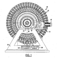
- FIGS. 1-9 illustrate a presently preferred embodiment of the present invention in the form of a machine 30 for compression molding sealing liners within plastic closure shells.
- Machine 30 includes a wheel 32 mounted on a shaft 34 ( FIG. 1 ) between spaced supports 36.
- Shaft 34 is coupled by a pulley 38, a belt 40 and a gear box 42 to a motor 44 for rotating shaft 34 and wheel 32 around a horizontal axis.
- Other suitable wheel drive means can be employed.
- Wheel 32 includes a hub (which may be part of shaft 34) and a support 46 ( FIGS. 3 , 4 and 5 ) extending radially from the hub.
- Support 46 in the illustrated embodiment of the invention is in the form of a circular plate 48.
- Plate 48 has a plurality of radially outwardly opening peripheral pockets 49 in an equally spaced circumferential array.
- a rod 50 is slidably supported by sleeve bearings 52 within each pocket 49.
- a pair of cam rollers 54, 55 are rotatably mounted on a shaft 56 at the outer end of each rod 50 and receive lubricant through a fitting 58.
- Each shaft 56 is carried by a mounting block 62 secured at or adjacent to the outer end of rod 50.
- a stabilizer bar 60 extends from each mounting block 62 and cooperates with spaced rollers 64, 66 ( FIG. 7 ) on plate 48 for preventing rotation of rod 50 within pocket 49.
- a pair of radially spaced external supports 68,70 are provided on support plate 48. As best seen in FIG. 2 , supports 68,70 preferably are in the form of respective circumferentially continuous radially inner and outer annular support rings.
- a plurality of angularly spaced molds 72 are disposed around wheel 32, preferably adjacent to the periphery of the wheel. Each mold 72 includes a radially inner first mold segment 76 and a second mold segment 78 in radially outward alignment with an associated first mold segment 76.
- the radially inner first mold segment 76 is a male mold segment
- the radially outer second mold segment 78 is a female mold segment, although these mold segments could be reversed in accordance with the broadest principles of the present invention.
- Molds 72 preferably are identical. FIGS. 3 and 4 show mold 72 open, and FIG. 5 shows mold 72 closed.
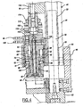
- male first mold segment 76 includes a core assembly 80 slidably mounted by a bearing 82 within a corresponding opening in outer support 70.
- Core assembly 82 includes a core tip 84 mounted on an inner pin 90, which is secured by screws 91 to a core manifold block 92 by springs 93 within pockets on the manifold block.
- Springs 93 cut through pins 95, which extend through openings in the base of inner pin 90, to engage the edge of collar 86.
- Pins 88 in collar 86 extend into slots on the skirt of tip 84 to limit outward movement of collar 86 with respect to tip 84.
- a coolant tube 94 extends from a first coolant fitting 96 on manifold block 92 through the hollow interior of pin 90 to a position adjacent to the inner face of tip 84. Coolant tube 90 is retained between the inner face of tip 84 and a counterbore in the end of pin 90. An annular passage 98, between pin 90 and the outer surface of tube 94, extends to a second coolant fitting 100 on block 92. Thus, coolant may be circulated from fitting 96 through tube 94 to the inner face of tip 84, and thence through passage 98 to fitting 100 (or in the opposite direction).
- a third fitting 102 ( FIG.
- manifold block 92 for selectively applying either vacuum or air under pressure through a passage 104 in block 92, through a passage 106 in pin 90, and then between sleeve 86 and tip 84.
- Fitting 102 may selectively be connected to vacuum for withdrawing air from the mold cavity during the compression molding operation to help reduce the occurrence of bubbles within the liner, and to air under pressure to assist removal of the closure and compression molded liner from the core assembly.
- a spring 108 ( FIGS. 3 , 4 and 18 ) is disposed between manifold block 92 and support 68 on support plate 48.
- Spring 108 in the preferred embodiment of the invention includes a coil spring 110 captured in compression between a head 112 and a base 114.
- Head 112 is adjustable with respect to base 114 by means of a screw 116 for adjusting the force applied by spring 110.
- Base 114 is mounted on support 68 by means of a screw 118.
- Head 112 is in abutting engagement with the radially inner end of manifold block 92.
- a stop 120 is mounted on manifold block 92 for engagement with outer support 72 to form an outer stop to movement of mold core assembly 76 under the force of spring 108.
- female second mold segment 78 is in the form of a nest, in which preformed closure shells 122 are placed on a platform 74 that is carried by block 62.
- a guide 124 is mounted on platform 74 for holding the shell in position.
- Guide 124 includes an opening for receiving core assembly 80 of male first mold segment 76 during radial inward motion of female second mold segment 78.
- Rollers 54, 55 on rod 50 and support block 62 engage cams 126, 128 ( FIGS. 1-3 and 5 ) that are disposed adjacent to the periphery of wheel 32.
- Cam 126 extends around the periphery of wheel 32 to move female second mold segments to the closed position ( FIG. 4 ) and hold the mold segments closed.
- Cam 128 is disposed adjacent to the lower portion of wheel 32 to pull second mold segments 78 open.
- directional words such as “upper” and “lower” are employed by way of description and not limitation with respect to the upright orientation of machine 30 illustrated in FIG. 1 .
- Directional words such as “radially inner” and “radially outer” are employed by way of description and not limitation with respect to the horizontal axis of wheel rotation).
- second mold segments 78 are pulled radially outwardly in sequence by cam 128 engaged with rollers 55, so that the second mold segments are opened radially outwardly with respect to first mold segments 76.
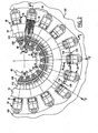
- closure shells 122 With the mold segments open, closure shells 122, with sealing liners compression molded therein, are extracted from second mold segments 78 by a molded part removal device 130 ( FIGS. 1 , 2 and 8 ).
- a premade plastic closure shell is then placed within the nest of second mold segment 78 by a mold charge placement device 132 ( FIGS. 1 , 2 and 9 ).
- the sealing liner mold charge is placed within the closure shell prior to placement of the shell into the nest.
- Continued rotation of wheel 32 functions through rollers 54 and cam 126 to close second mold segments 78 in sequence against first mold segments 76 to compression mold the charge of liner material within the closure shell.
- Springs 108 function to absorb excess force on first mold segments 76. The molds remain closed for cooling and set-up of the compression molded liner material until the molds are opened by cam 128 and rollers 55 as previously described.
- FIG. 8 schematically illustrates an embodiment of molded part removal device 130 in accordance with a presently preferred embodiment of the invention.
- Device 130 includes a stripper wheel 134 having angularly spaced pockets 136 for receiving closure shells 122 from mold segments 78 as the mold segments pass in sequence with the molds open.
- FIG. 9 schematically illustrates one embodiment of mold charge placement device 132 in accordance with the present invention.
- Device 132 includes a loader/placement wheel 138 having a circumferential array of angularly spaced pockets 140 for receiving premade closure shells in sequence from a shell loader or infeed 141.
- a series of pins 142 are carried by wheel 138 and extends radially into respective pockets 140.
- a coil spring 144 is captured in compression between each pin 142 and wheel 138 for biasing the pin radially outwardly (with respect to the axis of wheel 138) into the associated pocket 140.
- a guide rail 146 surrounds at least a portion of the periphery of wheel 138.
- Guide rail 146 includes a portion 148 that is linear and tangential to the axis of rotation of wheel 138.
- a mold charge placement apparatus 150 is disposed adjacent to wheel 138 and guide rail 146 for placing charges of compression moldable resin liner material into each premade closure shell 122 as the closure shell is moved along portion 148 of guide rail 146.
- shells 122 are biased by pins 142 and springs 144 into engagement with the inner surface of guide rail 146.
- the mold charges are placed in the shells in sequence as the shells travel along linear portion 148 for enhanced control of mold charge placement, which preferably is in the center of each closure shell for enhanced flow of material during the compression molding operation.
- Mold charge placement apparatus may be of any suitable type, such as that disclosed in U.S. Patent 5,603,964 for example.
- Wheel 134 in FIGS. 2 and 8 , and wheel 138 in FIGS. 2 and 9 are rotated in synchronism with rotation of wheel 32 ( FIG. 1 ).
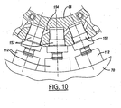
- FIG. 10 illustrates a modification to the embodiment of FIGS. 2-5 , in which the coil-type springs 108 in FIGS. 2-5 are replaced by gas springs 152, such as nitrogen gas springs.
- Gas springs 152 can be self-contained, or can be interconnected by passages 154. in inner support 68, with support 68 thus forming a spring gas manifold.
- FIGS. 11-22 illustrate a machine 160 for compression molding sealing liners within premade closure shells in accordance with another embodiment of the invention.
- Machine 160 of FIGS. 11-22 differs from machine 30 of FIGS. 1-9 primarily in that the premade closure shells and the mold charges of liner material are inserted into the molds in sequence when the molds are open. That is, the mold charges are placed within the premade shells after the shells are inserted into the molds, preferably by placing the mold charges into pockets on the faces of the male first mold segments when the mold segments are open.
- Parts or elements in FIGS. 11-22 (and 23) that are identical or similar to corresponding parts or elements in the embodiment of FIGS. 1-9 (and 10) are indicated by correspondingly identical reference numerals. The description of the embodiments of FIGS. 11-22 and 23 will be addressed primarily to the differences between these embodiments and the embodiments of FIGS. 1-9 and 10.
- Machine 160 includes wheel 162 that is rotatable around a horizontal axis.
- a plurality of molds 164 are disposed around wheel 162, preferably around the periphery of the wheel.
- Each mold 164 includes a first mold segment 166, preferably a male mold segment, and a second mold segment 78, preferably a female mold segment, disposed radially outwardly of the associated first mold segment 166.
- Female second mold segments 78 are engaged by cams 126, 128 disposed adjacent to wheel 162 to pull the female mold segments open to remove molded parts and insert shells and mold charges between the mold segments, and to push the female mold segments closed against the male mold segment to compression mold the liners.
- the molds are opened at the top of the wheel, rather than at the bottom of the wheel in FIGS. 1-9 .
- Mold segments 166 preferably are identical, and include a mold core assembly 168 slidably mounted on support 70 by bearings 82 and urged radially outwardly by springs 108.
- Each core assembly 168 includes a central core pin 170 mounted by a plate 171 ( FIGS. 12 , 13 and 21 ) within a support cup 172 ( FIGS. 12-13 and 20 ) slidably engaged with bearing 82.
- a core sleeve 174 ( FIGS. 12-14 ) slidably surrounds core pin 70.
- Core sleeve 174 is an assembly of an inner tube 176, which has a radially outwardly facing end wall 178, and an outer sleeve 180 that coaxially surrounds inner tube 176 and is secured to the outer periphery of end wall 178.
- the inner surface of inner tube 176 is slidably received on core pin 170, while an annular cavity 182 ( FIG. 14 ) is formed between the outer surface of inner tube 176 and the surrounding outer sleeve 180.
- An intermediate sleeve 184 ( FIGS. 12-13 and 19 ) is mounted to the outwardly flared inner end 186 of inner tube 176, and extends into annular cavity 182 so as to form in assembly an inner annular cavity 188 and an outer annular cavity 190 ( FIG. 13 ).
- a manifold block 192 ( FIGS. 12-13 and 17 ) is mounted on the radially inner end of outer sleeve 180.
- a first fitting 194 is mounted on manifold block 192 in communication with outer annular passage 190.
- a second fitting 196 is mounted on manifold block 192 in communication with inner annular passage 188.
- Manifold block 192 is secured to the end of sleeve 180 and is slidable within a support sleeve 207.
- Support sleeve 207 ( FIGS. 12-13 and 16 ) seats on plate 171 within support cup 172.
- coolant may be circulated from fitting 196 to inner annular passage 188 through an opening 198 adjacent to the radially inner end of intermediate sleeve 184, radially outwardly to outer annular passage 190 through passage 188 and a circumferential array of openings 200 at the opposing radially outer end of intermediate sleeve 184, radially inwardly along outer annular passage 190 through an opening 202 at the radially inner end of sleeve 180, and then through manifold block 192 to fitting 194.
- the flow direction can be reversed.
- Fittings 194, 196 extend laterally through an elongated opening 197 in support cup 172 to accommodate movement of manifold block 192 within support cup 172.
- a first coil spring 204 ( FIG. 13 ) is captured in compression between an outer flange 206 on sleeve 180 and the radially outer edge of support sleeve 207. Core sleeve 174 thus is biased by spring 204 radially outwardly with respect to core pin 170.
- a second coil spring 208 ( FIG. 13 ) is captured in compression between an outer shoulder on support sleeve 207 and an outer collar 210 ( FIGS. 12-13 and 15 ) surrounding the radially outer end of core sleeve 174. Outer collar thus is biased radially outwardly, with outward movement being limited by a stop ring 211 ( FIGS. 12-13 and 22 ) secured over the end of support cup 172 to complete core assembly 168.
- a pocket 212 is formed between the end of core pin 170 and surrounding core sleeve 174 urged radially outwardly by spring 204.
- a mold charge placement device 214 ( FIGS. 11-13 ) is disposed adj acent to wheel 164 for placing sequential mold charges into sequential pockets 212 as first mold segments 166 pass in sequence adjacent to the placement device.
- Mold charge placement device 214 is generally of the type disclosed in above-noted U.S. Patent 5,603,964 , the disclosure of which is incorporated herein by reference.
- a wheel 218 is rotatable around a vertical axis in synchronism with rotation of vertical mold wheel 162 and carries one or more nests 216. Nests 216 are connected by passages 220 in wheel 218 for application of vacuum and air under pressure to the interior of the nests.
- Nests 216 receive and cut mold charges from an extruder nozzle or the like (not shown), and carry the mold charges to a position overlying pockets 212 in mold segments 166 in sequence. At this position, air under pressure is applied to nest 216 so as to discharge the mold charge, illustrated schematically at 222 in FIGS. 12 and 13 , into pocket 212. Further rotation of wheel 162 clears pellet placement device 214, and second mold segment 78 is closed over first mold segment 166 by operation of cam 126 as previously described. After full rotation of wheel 164, as previously described, the closure shell with compression molded sealing liner is removed from the mold.
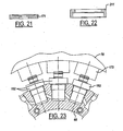
- FIG. 23 illustrates a modification to the embodiment of FIGS. 1-22 , in which coil-type springs 108 are replaced by gas springs 152, such as nitrogen gas springs.
Landscapes
- Engineering & Computer Science (AREA)
- Mechanical Engineering (AREA)
- Robotics (AREA)
- Casting Or Compression Moulding Of Plastics Or The Like (AREA)
- Moulds For Moulding Plastics Or The Like (AREA)
Description
- The present invention is directed to a vertical wheel machine and method for compression molding sealing liners within premade closure shells.
- Machines for compression molding sealing liners within closure shells typically include a turret or carousel that rotates around a vertical axis. Machines of that type are illustrated in
US-A 3,827,843 ,US-A 3,439,718 andUS-B 5,451,360 . A plurality of molds are provided around the periphery of the carousel in the form of male and female mold sections that are aligned along vertical axes parallel to the axis of rotation. Cams drive one or both of the mold sections of each pair between an open position, in which a molded part is removed from the mold and a premade shell and a charge of plastic liner material are placed in the female mold section, and a closed position in which the male and female mold sections are brought together to compression mold the liner within the shell. -
GB-A 0502977 US 3,210,805 shows a molding machine for plastic packings from plastic tape, the machine comprising a vertical wheel rotating around a horizontal axis.US-A-3655 612 discloses a moulding machine for ecapsulating electronic parts by using moulds rotatable around a horizontal axis. Transferring plungers inject the material into the mould cavity. No moulds for making sealing liners are provided. - Although vertical axis carousel-type machines of the noted type have enjoyed substantial commercial acceptance and success, innovation remains desirable. In particular, in vertical axis carousel-type machines, the weight of the rotating equipment is parallel to the vertical axis of rotation, creating a bending moment with respect to the axis of rotation and the bearings and shaft that support the carousel. Carousel-type machines also require a substantial amount of valuable floor space in a manufacturing facility.
- It is a general object of the present invention to provide an apparatus and method for compression molding sealing liners within premade closure shells that reduce the forces applied to the support frame and bearings, and/or reduce maintenance requirements and the amount of energy needed to operate the machine, and/or reduce the amount of floor space required per machine.
- The present invention involves a number of aspects that can be implemented separately from or in combination with each other.
- An apparatus for compression molding sealing liners in premade closure shells, in accordance with a first aspect of presently preferred embodiments of the invention, includes a shell loader for presenting premade closure shells in sequence, a mold charge placement device for placing charges of liner material into the premade shells, and a vertical wheel molding machine for receiving the closure shells in sequence from the loader and compression molding the mold charges to form sealing liners within the closure shells. The vertical wheel molding machine preferably includes a wheel mounted for rotation around a horizontal axis and a plurality of angularly spaced molds disposed around the wheel. Each of the molds preferably includes a first mold segment and a second mold segment disposed radially outwardly of the first mold segment. One of the first and second mold segments, preferably the second mold segment, is a female mold segment that includes a nest for receiving a premade closure shell. The other of the first and second mold segments, preferably the first mold segment, is a male mold segment that includes a core for engaging and compression molding the mold charge of liner material within the shell. In two disclosed embodiments of the invention, the mold charge of liner material either is placed within the premade closure shell prior to placement of the shell within the nest, or is placed within the shell after placement of the shell in the nest, preferably by placing the mold charge in a pocket on the mold core. The second mold segments preferably are moved radially inwardly and outwardly by at least one cam disposed adjacent to the wheel for engaging the second mold segments as the wheel rotates around its axis.
- A method of compression molding sealing liners within premade closure shells, in accordance with another aspect of the invention, includes providing a wheel mounted for rotation around a horizontal axis and a plurality of angularly spaced molds disposed around the wheel. Each of the molds includes a first mold segment and a second mold segment disposed radially outwardly of the first mold segment. As the wheel is rotated around its horizontal axis, the second mold segments are moved in sequence radially with respect to the associated first mold segments between a radially inner closed position and a radially outer open position spaced from the associated first mold segment. With the mold segments in the open position, closure shells with compression molded sealing liners are removed from the mold, and a premade closure shell and mold charge of liner material are placed in the mold. The mold segments are then closed as the wheel rotates to compression mold the mold charge of liner material between the mold segments. In the disclosed embodiments of the invention, the mold charge of liner material is placed into the premade shells either before or after placing the shells into the molds.
- The invention, together with additional objects, features, advantages and aspects thereof, will best be understood from the following description, the appended claims and the accompanying drawings, in which:
-
FIG. 1 is a side elevational view of a compression molding machine in accordance with one presently preferred embodiment of the invention; -
FIG. 2 is an enlargement of a lower portion of the machine inFIG. 1 ; -
FIGS. 3 is a sectional view taken substantially along the lines 3-3 inFIG. 2 ; -
FIG. 4 is an enlargement of a portion ofFIG. 3 ; -
FIG. 5 is a sectional view taken substantially along the line 5-5 inFIG. 2 ; -
FIG. 6 is a fragmentary sectional view taken substantially along the line 6-6 inFIG. 3 ; -
FIG. 7 is a fragmentary elevational view taken from thedirection 7 inFIG. 3 ; -
FIG. 8 is a schematic diagram of a molded part removal device, taken substantially from the direction 8 inFIG. 2 ; -
FIG. 9 is a schematic diagram of a mold charge placement device, being taken substantially from the direction 9 inFIG. 2 ; -
FIG. 10 is a fragmentary partially sectioned elevational view of a modification to the embodiment illustrated inFIGS. 1 and2 ; -
FIG. 11 is a fragmentary elevational view of a compression molding machine in accordance with another presently preferred embodiment of the invention; -
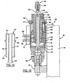
FIG. 12 is a fragmentary sectional view taken substantially along the line 12-12 inFIG. 11 ; -
FIG. 12A is a fragmentary elevational view taken from thedirection 12A inFIG. 12 ; -
FIG. 13 is an enlargement of a portion ofFIG. 12 ; -
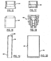
FIGS. 14-22 are sectional views of components in the mold core assembly illustrated inFIGS. 12 and13 ; and -
FIG. 23 is a fragmentary partially sectioned elevational view of a modification to the machine ofFIG. 11 . -
FIGS. 1-9 illustrate a presently preferred embodiment of the present invention in the form of amachine 30 for compression molding sealing liners within plastic closure shells.Machine 30 includes awheel 32 mounted on a shaft 34 (FIG. 1 ) betweenspaced supports 36.Shaft 34 is coupled by apulley 38, abelt 40 and agear box 42 to amotor 44 for rotatingshaft 34 andwheel 32 around a horizontal axis. Other suitable wheel drive means can be employed.Wheel 32 includes a hub (which may be part of shaft 34) and a support 46 (FIGS. 3 ,4 and5 ) extending radially from the hub.Support 46 in the illustrated embodiment of the invention is in the form of acircular plate 48.Plate 48 has a plurality of radially outwardly openingperipheral pockets 49 in an equally spaced circumferential array. Arod 50 is slidably supported bysleeve bearings 52 within eachpocket 49. A pair ofcam rollers shaft 56 at the outer end of eachrod 50 and receive lubricant through afitting 58. Eachshaft 56 is carried by amounting block 62 secured at or adjacent to the outer end ofrod 50. Astabilizer bar 60 extends from eachmounting block 62 and cooperates withspaced rollers 64, 66 (FIG. 7 ) onplate 48 for preventing rotation ofrod 50 withinpocket 49. - A pair of radially spaced
external supports support plate 48. As best seen inFIG. 2 , supports 68,70 preferably are in the form of respective circumferentially continuous radially inner and outer annular support rings. A plurality of angularly spacedmolds 72 are disposed aroundwheel 32, preferably adjacent to the periphery of the wheel. Eachmold 72 includes a radially innerfirst mold segment 76 and asecond mold segment 78 in radially outward alignment with an associatedfirst mold segment 76. In the preferred embodiments of the invention, the radially innerfirst mold segment 76 is a male mold segment, and the radially outersecond mold segment 78 is a female mold segment, although these mold segments could be reversed in accordance with the broadest principles of the present invention.Molds 72 preferably are identical.FIGS. 3 and4 show mold 72 open, andFIG. 5 showsmold 72 closed. - Referring to
FIGS. 3-5 , malefirst mold segment 76 includes acore assembly 80 slidably mounted by abearing 82 within a corresponding opening inouter support 70.Core assembly 82 includes acore tip 84 mounted on aninner pin 90, which is secured byscrews 91 to acore manifold block 92 bysprings 93 within pockets on the manifold block.Springs 93 cut throughpins 95, which extend through openings in the base ofinner pin 90, to engage the edge ofcollar 86.Pins 88 incollar 86 extend into slots on the skirt oftip 84 to limit outward movement ofcollar 86 with respect to tip 84. Acoolant tube 94 extends from a first coolant fitting 96 onmanifold block 92 through the hollow interior ofpin 90 to a position adjacent to the inner face oftip 84.Coolant tube 90 is retained between the inner face oftip 84 and a counterbore in the end ofpin 90. Anannular passage 98, betweenpin 90 and the outer surface oftube 94, extends to a second coolant fitting 100 onblock 92. Thus, coolant may be circulated from fitting 96 throughtube 94 to the inner face oftip 84, and thence throughpassage 98 to fitting 100 (or in the opposite direction). A third fitting 102 (FIG. 6 ) is carried bymanifold block 92 for selectively applying either vacuum or air under pressure through apassage 104 inblock 92, through apassage 106 inpin 90, and then betweensleeve 86 andtip 84. Fitting 102 may selectively be connected to vacuum for withdrawing air from the mold cavity during the compression molding operation to help reduce the occurrence of bubbles within the liner, and to air under pressure to assist removal of the closure and compression molded liner from the core assembly. - A spring 108 (
FIGS. 3 ,4 and18 ) is disposed betweenmanifold block 92 andsupport 68 onsupport plate 48.Spring 108 in the preferred embodiment of the invention includes acoil spring 110 captured in compression between ahead 112 and abase 114.Head 112 is adjustable with respect tobase 114 by means of ascrew 116 for adjusting the force applied byspring 110.Base 114 is mounted onsupport 68 by means of ascrew 118.Head 112 is in abutting engagement with the radially inner end ofmanifold block 92. Astop 120 is mounted onmanifold block 92 for engagement withouter support 72 to form an outer stop to movement ofmold core assembly 76 under the force ofspring 108. As noted above, femalesecond mold segment 78 is in the form of a nest, in which preformedclosure shells 122 are placed on aplatform 74 that is carried byblock 62. Aguide 124 is mounted onplatform 74 for holding the shell in position.Guide 124 includes an opening for receivingcore assembly 80 of malefirst mold segment 76 during radial inward motion of femalesecond mold segment 78.Rollers rod 50 andsupport block 62 engagecams 126, 128 (FIGS. 1-3 and5 ) that are disposed adjacent to the periphery ofwheel 32.Cam 126 extends around the periphery ofwheel 32 to move female second mold segments to the closed position (FIG. 4 ) and hold the mold segments closed.Cam 128 is disposed adjacent to the lower portion ofwheel 32 to pullsecond mold segments 78 open. (It will be appreciated that directional words such as "upper" and "lower" are employed by way of description and not limitation with respect to the upright orientation ofmachine 30 illustrated inFIG. 1 . Directional words such as "radially inner" and "radially outer" are employed by way of description and not limitation with respect to the horizontal axis of wheel rotation). - Thus, as
wheel 32 rotates in the clockwise direction inFIG. 1 , the counterclockwise direction inFIG. 2 and into the page inFIGS. 3 ,4 and5 ,second mold segments 78 are pulled radially outwardly in sequence bycam 128 engaged withrollers 55, so that the second mold segments are opened radially outwardly with respect tofirst mold segments 76. With the mold segments open,closure shells 122, with sealing liners compression molded therein, are extracted fromsecond mold segments 78 by a molded part removal device 130 (FIGS. 1 ,2 and8 ). A premade plastic closure shell is then placed within the nest ofsecond mold segment 78 by a mold charge placement device 132 (FIGS. 1 ,2 and9 ). In this embodiment of the invention, the sealing liner mold charge is placed within the closure shell prior to placement of the shell into the nest. Continued rotation ofwheel 32 functions throughrollers 54 andcam 126 to closesecond mold segments 78 in sequence againstfirst mold segments 76 to compression mold the charge of liner material within the closure shell.Springs 108 function to absorb excess force onfirst mold segments 76. The molds remain closed for cooling and set-up of the compression molded liner material until the molds are opened bycam 128 androllers 55 as previously described. -
FIG. 8 schematically illustrates an embodiment of moldedpart removal device 130 in accordance with a presently preferred embodiment of the invention.Device 130 includes astripper wheel 134 having angularly spacedpockets 136 for receivingclosure shells 122 frommold segments 78 as the mold segments pass in sequence with the molds open. -
FIG. 9 schematically illustrates one embodiment of moldcharge placement device 132 in accordance with the present invention.Device 132 includes a loader/placement wheel 138 having a circumferential array of angularly spaced pockets 140 for receiving premade closure shells in sequence from a shell loader orinfeed 141. A series ofpins 142 are carried bywheel 138 and extends radially into respective pockets 140. Acoil spring 144 is captured in compression between eachpin 142 andwheel 138 for biasing the pin radially outwardly (with respect to the axis of wheel 138) into the associated pocket 140. Aguide rail 146 surrounds at least a portion of the periphery ofwheel 138.Guide rail 146 includes aportion 148 that is linear and tangential to the axis of rotation ofwheel 138. A moldcharge placement apparatus 150 is disposed adjacent towheel 138 andguide rail 146 for placing charges of compression moldable resin liner material into eachpremade closure shell 122 as the closure shell is moved alongportion 148 ofguide rail 146. Thus,shells 122 are biased bypins 142 and springs 144 into engagement with the inner surface ofguide rail 146. The mold charges are placed in the shells in sequence as the shells travel alonglinear portion 148 for enhanced control of mold charge placement, which preferably is in the center of each closure shell for enhanced flow of material during the compression molding operation. Mold charge placement apparatus may be of any suitable type, such as that disclosed inU.S. Patent 5,603,964 for example.Wheel 134 inFIGS. 2 and8 , andwheel 138 inFIGS. 2 and9 , are rotated in synchronism with rotation of wheel 32 (FIG. 1 ). -
FIG. 10 illustrates a modification to the embodiment ofFIGS. 2-5 , in which the coil-type springs 108 inFIGS. 2-5 are replaced bygas springs 152, such as nitrogen gas springs. Gas springs 152 can be self-contained, or can be interconnected bypassages 154. ininner support 68, withsupport 68 thus forming a spring gas manifold. -
FIGS. 11-22 illustrate amachine 160 for compression molding sealing liners within premade closure shells in accordance with another embodiment of the invention.Machine 160 ofFIGS. 11-22 differs frommachine 30 ofFIGS. 1-9 primarily in that the premade closure shells and the mold charges of liner material are inserted into the molds in sequence when the molds are open. That is, the mold charges are placed within the premade shells after the shells are inserted into the molds, preferably by placing the mold charges into pockets on the faces of the male first mold segments when the mold segments are open. Parts or elements inFIGS. 11-22 (and 23) that are identical or similar to corresponding parts or elements in the embodiment ofFIGS. 1-9 (and 10) are indicated by correspondingly identical reference numerals. The description of the embodiments ofFIGS. 11-22 and23 will be addressed primarily to the differences between these embodiments and the embodiments ofFIGS. 1-9 and10. -
Machine 160 includeswheel 162 that is rotatable around a horizontal axis. A plurality ofmolds 164 are disposed aroundwheel 162, preferably around the periphery of the wheel. Eachmold 164 includes afirst mold segment 166, preferably a male mold segment, and asecond mold segment 78, preferably a female mold segment, disposed radially outwardly of the associatedfirst mold segment 166. Femalesecond mold segments 78 are engaged bycams wheel 162 to pull the female mold segments open to remove molded parts and insert shells and mold charges between the mold segments, and to push the female mold segments closed against the male mold segment to compression mold the liners. Inmachine 160, the molds are opened at the top of the wheel, rather than at the bottom of the wheel inFIGS. 1-9 . -
Mold segments 166 preferably are identical, and include amold core assembly 168 slidably mounted onsupport 70 bybearings 82 and urged radially outwardly bysprings 108. Eachcore assembly 168 includes acentral core pin 170 mounted by a plate 171 (FIGS. 12 ,13 and21 ) within a support cup 172 (FIGS. 12-13 and20 ) slidably engaged withbearing 82. A core sleeve 174 (FIGS. 12-14 ) slidably surroundscore pin 70.Core sleeve 174 is an assembly of aninner tube 176, which has a radially outwardly facingend wall 178, and anouter sleeve 180 that coaxially surroundsinner tube 176 and is secured to the outer periphery ofend wall 178.. The inner surface ofinner tube 176 is slidably received oncore pin 170, while an annular cavity 182 (FIG. 14 ) is formed between the outer surface ofinner tube 176 and the surroundingouter sleeve 180. An intermediate sleeve 184 (FIGS. 12-13 and19 ) is mounted to the outwardly flaredinner end 186 ofinner tube 176, and extends intoannular cavity 182 so as to form in assembly an innerannular cavity 188 and an outer annular cavity 190 (FIG. 13 ). - A manifold block 192 (
FIGS. 12-13 and17 ) is mounted on the radially inner end ofouter sleeve 180. Afirst fitting 194 is mounted onmanifold block 192 in communication with outerannular passage 190. Asecond fitting 196 is mounted onmanifold block 192 in communication with innerannular passage 188. Manifold block 192 is secured to the end ofsleeve 180 and is slidable within asupport sleeve 207. Support sleeve 207 (FIGS. 12-13 and16 ) seats onplate 171 withinsupport cup 172. Thus, coolant may be circulated from fitting 196 to innerannular passage 188 through anopening 198 adjacent to the radially inner end ofintermediate sleeve 184, radially outwardly to outerannular passage 190 throughpassage 188 and a circumferential array ofopenings 200 at the opposing radially outer end ofintermediate sleeve 184, radially inwardly along outerannular passage 190 through anopening 202 at the radially inner end ofsleeve 180, and then throughmanifold block 192 to fitting 194. The flow direction can be reversed.Fittings elongated opening 197 insupport cup 172 to accommodate movement ofmanifold block 192 withinsupport cup 172. - A first coil spring 204 (
FIG. 13 ) is captured in compression between anouter flange 206 onsleeve 180 and the radially outer edge ofsupport sleeve 207.Core sleeve 174 thus is biased byspring 204 radially outwardly with respect tocore pin 170. A second coil spring 208 (FIG. 13 ) is captured in compression between an outer shoulder onsupport sleeve 207 and an outer collar 210 (FIGS. 12-13 and15 ) surrounding the radially outer end ofcore sleeve 174. Outer collar thus is biased radially outwardly, with outward movement being limited by a stop ring 211 (FIGS. 12-13 and22 ) secured over the end ofsupport cup 172 to completecore assembly 168. When the mold segments are open (FIGS. 12 and13 ), apocket 212 is formed between the end ofcore pin 170 and surroundingcore sleeve 174 urged radially outwardly byspring 204. - A mold charge placement device 214 (
FIGS. 11-13 ) is disposed adj acent towheel 164 for placing sequential mold charges intosequential pockets 212 asfirst mold segments 166 pass in sequence adjacent to the placement device. Moldcharge placement device 214 is generally of the type disclosed in above-notedU.S. Patent 5,603,964 , the disclosure of which is incorporated herein by reference. A wheel 218 is rotatable around a vertical axis in synchronism with rotation ofvertical mold wheel 162 and carries one ormore nests 216.Nests 216 are connected bypassages 220 in wheel 218 for application of vacuum and air under pressure to the interior of the nests.Nests 216 receive and cut mold charges from an extruder nozzle or the like (not shown), and carry the mold charges to aposition overlying pockets 212 inmold segments 166 in sequence. At this position, air under pressure is applied to nest 216 so as to discharge the mold charge, illustrated schematically at 222 inFIGS. 12 and13 , intopocket 212. Further rotation ofwheel 162 clearspellet placement device 214, andsecond mold segment 78 is closed overfirst mold segment 166 by operation ofcam 126 as previously described. After full rotation ofwheel 164, as previously described, the closure shell with compression molded sealing liner is removed from the mold. -
FIG. 23 illustrates a modification to the embodiment ofFIGS. 1-22 , in which coil-type springs 108 are replaced bygas springs 152, such as nitrogen gas springs. - There thus have been disclosed an apparatus and method for compression molding sealing lines within premade closure shells, which fully satisfy all of the objects and aims previously set forth. The invention has been described in conjunction with several presently preferred embodiments, and a number of additional modifications and variations have been discussed. Other modifications and variations readily will suggest themselves to persons of ordinary skill in the art. The invention is intended to embrace all such modifications and variations as fall within the spirit and broad scope of the appended claims.
Claims (23)
- Apparatus for compression molding sealing liners in closure shells, which includes:a shell loader (141) for presenting premade closure shells (122) in sequence,a mold charge placement device (132 or 214) for placing mold charges of liner material into the premade shells (122, anda molding machine for receiving closure shells (122) in sequence from said loader (141) and for compression molding the mold charges to form sealing liners within the closure shells (122), characterized in thatsaid molding machine is a vertical wheel molding machine (30 or 160) that includes:a wheel mounted (32 or 162) for rotation around a horizontal axis and a plurality of angularly spaced molds (72 or 164) disposed around said wheel,each of said molds (72; 164) including a fist mold segment (76 or 166) and a second mold segment (78) disposed radially outwardly of said first mold segment,one of said first and second mold segments including a nest for receiving a premade closure shell (122), and the other of said first and second mold segments including a core (80 or 168) for engaging and compression molding a mold charge within the shell (122).
- The apparatus set forth in claim 1 including means (126, 128) for moving said second mold segments (78) in sequence radially inwardly and outwardly as said wheel (32; 162) rotates around said horizontal axis.
- The apparatus set forth in claim 2 wherein said means (126, 128) includes at least one cam disposed adjacent to said wheel (32; 162) for engaging said second mold segments in sequence as said wheel rotates around said axis.
- The apparatus set forth in claim 1 wherein said wheel (32 or 162) includes a radially extending support (46) on which said molds (72; 164) are mounted.
- The apparatus set forth in claim 4 wherein said molds (72 or 164) are mounted adjacent to a periphery of said support (46).
- The apparatus set forth in claim 5 wherein said support (46) includes a plurality of angularly spaced radially outwardly opening pockets (49), and wherein said second mold segments (78) arse mounted on rods (50) slidably carried in said pockets (49).
- The apparatus set forth in claim 4 wherein each of said first mold segments (76 or 166) is mounted between radially spaced inner and outer supports (68, 70).
- The apparatus set forth in claim 7 wherein each of said first mold segments (76; 166) is slidably mounted in said radially outer support (70) and is coupled by a spring (108 or 152) to said radially inner support (68).
- The apparatus set forth in claim 8 wherein said spring (108; 152) comprises a coil spring or a gas spring.
- The apparatus set forth in claim 1 wherein said second mold segments (78) include said nests and said first mold segments (76 or 166) include said cores (80 or 168).
- The apparatus set forth in claim 10 wherein said mold charge placement device (132) places mold charges into the premade closure shells (122) in sequence prior to placement of the shells into said nests.
- The apparatus set forth in claim 11 wherein said mold charge placement device (132) includes:a mold charge placement apparatus (150),a placement wheel (138) rotatable around a vertical axis synchronism with rotation of said vertical wheel (32; 162) around said horizontal axis, said placement wheel (138) having peripheral pockets (140) for receiving the closure shells (122) in sequence,a guide rail (146) surrounding at least a portion of said placement wheel (138), andsprings (144) on said placement wheel (138) for engaging shells (122) in said pockets (140) and urging the shells (122) against said guide rail (146) to locate the shells (122) relative to said mold charge placement apparatus (150).
- The apparatus set forth in claim 12 wherein said guide rail (146) includes a portion (148) that is linear and tangential to said vertical axis so that the shells (122) travel in a linear path along said portion of said guide rail adjacent to said mold charge placement apparatus (150).
- The apparatus set forth in claim 12 wherein said springs (144) engage pins (142) carried by said placement wheel (138) for urging the shells (122) against said guide rail (146).
- The apparatus set forth in claim 10 wherein said mold charge placement device (214) places mold charges into the premade closure shells (122) in sequence after placement of the shells into said nests.
- The apparatus set forth in claim 15 wherein said mold charge placement device (214) places mold charges onto said cores (168) in sequence, with said cores placing said mold charges into said premade shells (122) when said second mold segment (78) and nest are closed against said core (168).
- The apparatus set forth in claim 16 wherein each of said cores (168) includes;a core pin (170) coupled to said wheel (162),a core sleeve (174) surrounding said core pin, anda spring (204) biasing said core sleeve radially outwardly with respect to said core pin to form a pocket between said core pin and said core sleeve for receiving a mold charge,wherein closing of said second mold segment (78) against said first mold segment (166) effects moving said core sleeve (174) against said spring (204) to reduce said pocket and compression mold the mold charge.
- The apparatus set forth in claim 17 including means (194, 196) for directing coolant through said core sleeve (174) to cool said core (168).
- The apparatus set forth in claim 18 wherein said core sleeve (174) forms an annular coolant cavity (182), wherein said core (168) includes an intermediate sleeve (184) positioned to divide said annular coolant cavity (182) into inner and outer annular coolant cavities, said intermediate sleeve (184) including passages (198, 200) for feeding coolant between said inner and outer annular cavities.
- The apparatus set forth in claim 1 wherein each of said cores (168) includes a passage (104) for application of vacuum at a tip of said core to remove air during compression molding of the mold charge.
- A method of compression molding sealing liners within premade closure shells (122), which includes the steps of:(a) providing a wheel (30 or 160) mounted for rotation around a horizontal axis and a plurality of angularly spaced molds (72 or 164) disposed around said wheel, each of said molds including a first mold segment (76 or 166) and a second mold segment (78) disposed radially outwardly of said first mold segment,(b) rotating a wheel (30; 60) around a horizontal axis,(c) as said wheel (30; 60) rotates, radially moving each of said second mold segments (78)_ in sequence with respect to the associated first mold segment (76; 166) between a radially inner closed position with said first mold segment and a radially outer open position spaced from the associated first mold segment,(d) with said mold segments (76, 78; 166) in said open position, removing a closure shell (122) with compression molded liner from said mold (72; 164), and placing a premade closure shell (122) and a mold charge of liner material into said mold, and(e) closing said mold segments (76, 78; 166) as said wheel (30, 160) rotates to compression mold the mold charge of liner material between said mold segments.
- The method set forth in claim 21 wherein said mold charge of liner material is placed into the premade closure shells (122) in said step (d) prior to placing the closure shells into said mold.
- The method set forth in claim 21 wherein the mold charge of liner material is placed into the premade closure shell (122) in said step (d) after placing the closure shell into said mold.
Applications Claiming Priority (2)
| Application Number | Priority Date | Filing Date | Title |
|---|---|---|---|
| US11/155,275 US7556488B2 (en) | 2005-06-17 | 2005-06-17 | Vertical wheel machine and method for compression molding sealing liners |
| PCT/US2006/021610 WO2006138090A1 (en) | 2005-06-17 | 2006-06-05 | Vertical wheel machine and method for compression molding sealing liners |
Publications (2)
| Publication Number | Publication Date |
|---|---|
| EP1901900A1 EP1901900A1 (en) | 2008-03-26 |
| EP1901900B1 true EP1901900B1 (en) | 2014-01-08 |
Family
ID=37067591
Family Applications (1)
| Application Number | Title | Priority Date | Filing Date |
|---|---|---|---|
| EP06772063.1A Not-in-force EP1901900B1 (en) | 2005-06-17 | 2006-06-05 | Vertical wheel machine and method for compression molding sealing liners |
Country Status (12)
| Country | Link |
|---|---|
| US (1) | US7556488B2 (en) |
| EP (1) | EP1901900B1 (en) |
| JP (1) | JP5205553B2 (en) |
| CN (1) | CN100584562C (en) |
| AU (1) | AU2006259759B9 (en) |
| BR (1) | BRPI0613143A2 (en) |
| CA (1) | CA2596815C (en) |
| MX (1) | MX2007009739A (en) |
| NZ (1) | NZ556798A (en) |
| RU (1) | RU2406605C2 (en) |
| WO (1) | WO2006138090A1 (en) |
| ZA (1) | ZA200707500B (en) |
Families Citing this family (4)
| Publication number | Priority date | Publication date | Assignee | Title |
|---|---|---|---|---|
| ITMO20130324A1 (en) | 2013-11-29 | 2015-05-30 | Sacmi | FORMING APPARATUS |
| ITUA20161676A1 (en) | 2016-03-15 | 2017-09-15 | Sacmi | Method and tool for assembling a female mold, and female mold arrangement. |
| JP6845318B2 (en) * | 2016-10-24 | 2021-03-17 | ダウ グローバル テクノロジーズ エルエルシー | Composite material forming and cutting tools |
| IT202300008304A1 (en) * | 2023-04-27 | 2024-10-27 | Sacmi | Compression molding method and apparatus |
Family Cites Families (20)
| Publication number | Priority date | Publication date | Assignee | Title |
|---|---|---|---|---|
| GB502977A (en) | 1937-10-01 | 1939-03-29 | Augustus Ludovic Merolle | Method of and apparatus for forming receptacle screw caps |
| SU99161A1 (en) * | 1950-10-28 | 1953-11-30 | Р.В. Григорьев | Installation for continuous vulcanization of molded products |
| US3210805A (en) | 1961-02-28 | 1965-10-12 | Hanai Mikihiko | Molding machines |
| US3439718A (en) | 1967-04-27 | 1969-04-22 | Continental Can Co | Rotary air-flow control valve for compound gun of crown cap lining machine |
| US3635612A (en) | 1969-10-29 | 1972-01-18 | Fortin Latchford Ltd | Molding machine |
| US3827843A (en) | 1972-01-26 | 1974-08-06 | Sycamore Mfg Co Inc | Apparatus for lining bottle crowns with thermoplastic material |
| JPS5462079A (en) * | 1977-10-24 | 1979-05-18 | Osaka Eiriyuu Kougiyou Kk | Device for making packing on bottle lid |
| JPS56151517A (en) | 1980-04-28 | 1981-11-24 | Japan Crown Cork Co Ltd | Embossing tool for embossing liner onto inside of crown cap shell |
| JPH033383Y2 (en) * | 1986-10-01 | 1991-01-29 | ||
| JP3062829B2 (en) * | 1991-02-13 | 2000-07-12 | 日本クラウンコルク株式会社 | Annular liner molding equipment |
| US5451360A (en) | 1993-10-14 | 1995-09-19 | Owens-Illinois Closure Inc. | Method and apparatus for compression molding closure liners |
| ITBO940242A1 (en) | 1994-05-23 | 1995-11-23 | Sacmi | EQUIPMENT FOR PRESSURE MOLDING OF ARTICLES IN PLASTIC MATERIAL, SUCH AS CAPSULES FOR THE CLOSING OF CONTAINERS AND SIMILAR. |
| US5947311A (en) | 1997-05-06 | 1999-09-07 | Owens-Illinois Closure Inc. | Plastic closure with liner having a periphery spaced from the skirt of the closure and a sealing surface angled axially with respect to the base wall of the closure |
| US6187235B1 (en) | 1998-08-31 | 2001-02-13 | Zapata Technologies Incorporated | Method for processing bottle caps |
| US6306330B1 (en) | 1999-07-23 | 2001-10-23 | Alena Closure Systems International | Two-step molding of liner components for a closure |
| US6422854B1 (en) | 1999-11-22 | 2002-07-23 | Alcoa Closure Systems International | Rotary cutter for cutting, measuring, and dispensing molten plastic |
| US6368094B1 (en) | 1999-11-22 | 2002-04-09 | Alcoa Closure Systems International | Multi-path compression molding apparatus |
| IT1321322B1 (en) * | 2000-05-05 | 2004-01-08 | Sacmi | CAROUSEL EQUIPMENT FOR THE MANUFACTURE, THROUGH THE OPENING MOLDING, OF PLASTIC CAPSULES |
| DE10026731C2 (en) | 2000-05-17 | 2002-08-14 | Fette Wilhelm Gmbh | Rotary tablet press for the production of multilayer tablets |
| US7331777B2 (en) * | 2005-04-19 | 2008-02-19 | Owens Illinois Closure Inc. | Compression molding machine |
-
2005
- 2005-06-17 US US11/155,275 patent/US7556488B2/en not_active Expired - Fee Related
-
2006
- 2006-06-05 ZA ZA200707500A patent/ZA200707500B/en unknown
- 2006-06-05 MX MX2007009739A patent/MX2007009739A/en active IP Right Grant
- 2006-06-05 AU AU2006259759A patent/AU2006259759B9/en not_active Ceased
- 2006-06-05 BR BRPI0613143-3A patent/BRPI0613143A2/en not_active IP Right Cessation
- 2006-06-05 JP JP2008516922A patent/JP5205553B2/en not_active Expired - Fee Related
- 2006-06-05 WO PCT/US2006/021610 patent/WO2006138090A1/en not_active Ceased
- 2006-06-05 CN CN200680021799.6A patent/CN100584562C/en not_active Expired - Fee Related
- 2006-06-05 NZ NZ556798A patent/NZ556798A/en not_active IP Right Cessation
- 2006-06-05 EP EP06772063.1A patent/EP1901900B1/en not_active Not-in-force
- 2006-06-05 CA CA2596815A patent/CA2596815C/en not_active Expired - Fee Related
- 2006-06-05 RU RU2008101803/05A patent/RU2406605C2/en not_active IP Right Cessation
Also Published As
| Publication number | Publication date |
|---|---|
| BRPI0613143A2 (en) | 2009-06-16 |
| NZ556798A (en) | 2009-11-27 |
| AU2006259759B9 (en) | 2011-03-31 |
| AU2006259759A1 (en) | 2006-12-28 |
| CA2596815A1 (en) | 2006-12-28 |
| RU2406605C2 (en) | 2010-12-20 |
| AU2006259759B2 (en) | 2010-11-11 |
| CA2596815C (en) | 2013-08-06 |
| MX2007009739A (en) | 2007-09-25 |
| JP2008543613A (en) | 2008-12-04 |
| RU2008101803A (en) | 2009-07-27 |
| CN100584562C (en) | 2010-01-27 |
| JP5205553B2 (en) | 2013-06-05 |
| US7556488B2 (en) | 2009-07-07 |
| WO2006138090A1 (en) | 2006-12-28 |
| EP1901900A1 (en) | 2008-03-26 |
| US20060284339A1 (en) | 2006-12-21 |
| ZA200707500B (en) | 2008-12-31 |
| CN101198452A (en) | 2008-06-11 |
Similar Documents
| Publication | Publication Date | Title |
|---|---|---|
| US7638082B2 (en) | Compression molding machine | |
| US7934920B2 (en) | Molding machine | |
| CA2596815C (en) | Vertical wheel machine and method for compression molding sealing liners | |
| US7566215B2 (en) | Apparatus for placing mold charges into a compression molding machine | |
| US7247014B2 (en) | Compression molding machine | |
| EP1954465B1 (en) | Method and machine for compression molding closure shells | |
| EP1901904B1 (en) | Compression molding machine | |
| US20090269431A1 (en) | Compression molding an annular closure shell | |
| KR20070031901A (en) | Method and apparatus for compression molding plastic articles |
Legal Events
| Date | Code | Title | Description |
|---|---|---|---|
| PUAI | Public reference made under article 153(3) epc to a published international application that has entered the european phase |
Free format text: ORIGINAL CODE: 0009012 |
|
| 17P | Request for examination filed |
Effective date: 20071004 |
|
| AK | Designated contracting states |
Kind code of ref document: A1 Designated state(s): AT BE BG CH CY CZ DE DK EE ES FI FR GB GR HU IE IS IT LI LT LU LV MC NL PL PT RO SE SI SK TR |
|
| DAX | Request for extension of the european patent (deleted) | ||
| RAP1 | Party data changed (applicant data changed or rights of an application transferred) |
Owner name: REXAM CLOSURE SYSTEMS INC. |
|
| RAP1 | Party data changed (applicant data changed or rights of an application transferred) |
Owner name: REXAM CLOSURE SYSTEMS INC. |
|
| DAX | Request for extension of the european patent (deleted) | ||
| 17Q | First examination report despatched |
Effective date: 20110509 |
|
| RIC1 | Information provided on ipc code assigned before grant |
Ipc: B29C 43/08 20060101ALI20120515BHEP Ipc: B29C 31/04 20060101AFI20120515BHEP Ipc: B29C 43/34 20060101ALI20120515BHEP Ipc: B29C 43/18 20060101ALN20120515BHEP Ipc: B29L 31/56 20060101ALI20120515BHEP |
|
| RAP1 | Party data changed (applicant data changed or rights of an application transferred) |
Owner name: BERRY PLASTICS CORPORATION |
|
| GRAP | Despatch of communication of intention to grant a patent |
Free format text: ORIGINAL CODE: EPIDOSNIGR1 |
|
| INTG | Intention to grant announced |
Effective date: 20130912 |
|
| RIC1 | Information provided on ipc code assigned before grant |
Ipc: B29C 43/34 20060101ALI20130902BHEP Ipc: B29C 43/18 20060101ALN20130902BHEP Ipc: B29C 31/04 20060101AFI20130902BHEP Ipc: B29L 31/56 20060101ALI20130902BHEP Ipc: B29C 43/08 20060101ALI20130902BHEP |
|
| GRAS | Grant fee paid |
Free format text: ORIGINAL CODE: EPIDOSNIGR3 |
|
| GRAA | (expected) grant |
Free format text: ORIGINAL CODE: 0009210 |
|
| AK | Designated contracting states |
Kind code of ref document: B1 Designated state(s): AT BE BG CH CY CZ DE DK EE ES FI FR GB GR HU IE IS IT LI LT LU LV MC NL PL PT RO SE SI SK TR |
|
| REG | Reference to a national code |
Ref country code: GB Ref legal event code: FG4D |
|
| REG | Reference to a national code |
Ref country code: CH Ref legal event code: EP |
|
| REG | Reference to a national code |
Ref country code: IE Ref legal event code: FG4D |
|
| REG | Reference to a national code |
Ref country code: AT Ref legal event code: REF Ref document number: 648418 Country of ref document: AT Kind code of ref document: T Effective date: 20140215 |
|
| REG | Reference to a national code |
Ref country code: DE Ref legal event code: R096 Ref document number: 602006039976 Country of ref document: DE Effective date: 20140220 |
|
| REG | Reference to a national code |
Ref country code: AT Ref legal event code: MK05 Ref document number: 648418 Country of ref document: AT Kind code of ref document: T Effective date: 20140108 |
|
| REG | Reference to a national code |
Ref country code: NL Ref legal event code: VDEP Effective date: 20140108 |
|
| REG | Reference to a national code |
Ref country code: LT Ref legal event code: MG4D |
|
| PG25 | Lapsed in a contracting state [announced via postgrant information from national office to epo] |
Ref country code: LT Free format text: LAPSE BECAUSE OF FAILURE TO SUBMIT A TRANSLATION OF THE DESCRIPTION OR TO PAY THE FEE WITHIN THE PRESCRIBED TIME-LIMIT Effective date: 20140108 Ref country code: IS Free format text: LAPSE BECAUSE OF FAILURE TO SUBMIT A TRANSLATION OF THE DESCRIPTION OR TO PAY THE FEE WITHIN THE PRESCRIBED TIME-LIMIT Effective date: 20140508 |
|
| PG25 | Lapsed in a contracting state [announced via postgrant information from national office to epo] |
Ref country code: PT Free format text: LAPSE BECAUSE OF FAILURE TO SUBMIT A TRANSLATION OF THE DESCRIPTION OR TO PAY THE FEE WITHIN THE PRESCRIBED TIME-LIMIT Effective date: 20140508 Ref country code: AT Free format text: LAPSE BECAUSE OF FAILURE TO SUBMIT A TRANSLATION OF THE DESCRIPTION OR TO PAY THE FEE WITHIN THE PRESCRIBED TIME-LIMIT Effective date: 20140108 Ref country code: FI Free format text: LAPSE BECAUSE OF FAILURE TO SUBMIT A TRANSLATION OF THE DESCRIPTION OR TO PAY THE FEE WITHIN THE PRESCRIBED TIME-LIMIT Effective date: 20140108 Ref country code: CY Free format text: LAPSE BECAUSE OF FAILURE TO SUBMIT A TRANSLATION OF THE DESCRIPTION OR TO PAY THE FEE WITHIN THE PRESCRIBED TIME-LIMIT Effective date: 20140108 Ref country code: SE Free format text: LAPSE BECAUSE OF FAILURE TO SUBMIT A TRANSLATION OF THE DESCRIPTION OR TO PAY THE FEE WITHIN THE PRESCRIBED TIME-LIMIT Effective date: 20140108 Ref country code: NL Free format text: LAPSE BECAUSE OF FAILURE TO SUBMIT A TRANSLATION OF THE DESCRIPTION OR TO PAY THE FEE WITHIN THE PRESCRIBED TIME-LIMIT Effective date: 20140108 Ref country code: ES Free format text: LAPSE BECAUSE OF FAILURE TO SUBMIT A TRANSLATION OF THE DESCRIPTION OR TO PAY THE FEE WITHIN THE PRESCRIBED TIME-LIMIT Effective date: 20140108 |
|
| PG25 | Lapsed in a contracting state [announced via postgrant information from national office to epo] |
Ref country code: LV Free format text: LAPSE BECAUSE OF FAILURE TO SUBMIT A TRANSLATION OF THE DESCRIPTION OR TO PAY THE FEE WITHIN THE PRESCRIBED TIME-LIMIT Effective date: 20140108 Ref country code: BE Free format text: LAPSE BECAUSE OF FAILURE TO SUBMIT A TRANSLATION OF THE DESCRIPTION OR TO PAY THE FEE WITHIN THE PRESCRIBED TIME-LIMIT Effective date: 20140108 |
|
| REG | Reference to a national code |
Ref country code: DE Ref legal event code: R097 Ref document number: 602006039976 Country of ref document: DE |
|
| PG25 | Lapsed in a contracting state [announced via postgrant information from national office to epo] |
Ref country code: RO Free format text: LAPSE BECAUSE OF FAILURE TO SUBMIT A TRANSLATION OF THE DESCRIPTION OR TO PAY THE FEE WITHIN THE PRESCRIBED TIME-LIMIT Effective date: 20140108 Ref country code: DK Free format text: LAPSE BECAUSE OF FAILURE TO SUBMIT A TRANSLATION OF THE DESCRIPTION OR TO PAY THE FEE WITHIN THE PRESCRIBED TIME-LIMIT Effective date: 20140108 Ref country code: EE Free format text: LAPSE BECAUSE OF FAILURE TO SUBMIT A TRANSLATION OF THE DESCRIPTION OR TO PAY THE FEE WITHIN THE PRESCRIBED TIME-LIMIT Effective date: 20140108 Ref country code: CZ Free format text: LAPSE BECAUSE OF FAILURE TO SUBMIT A TRANSLATION OF THE DESCRIPTION OR TO PAY THE FEE WITHIN THE PRESCRIBED TIME-LIMIT Effective date: 20140108 |
|
| PLBE | No opposition filed within time limit |
Free format text: ORIGINAL CODE: 0009261 |
|
| STAA | Information on the status of an ep patent application or granted ep patent |
Free format text: STATUS: NO OPPOSITION FILED WITHIN TIME LIMIT |
|
| PG25 | Lapsed in a contracting state [announced via postgrant information from national office to epo] |
Ref country code: SK Free format text: LAPSE BECAUSE OF FAILURE TO SUBMIT A TRANSLATION OF THE DESCRIPTION OR TO PAY THE FEE WITHIN THE PRESCRIBED TIME-LIMIT Effective date: 20140108 Ref country code: PL Free format text: LAPSE BECAUSE OF FAILURE TO SUBMIT A TRANSLATION OF THE DESCRIPTION OR TO PAY THE FEE WITHIN THE PRESCRIBED TIME-LIMIT Effective date: 20140108 |
|
| 26N | No opposition filed |
Effective date: 20141009 |
|
| REG | Reference to a national code |
Ref country code: DE Ref legal event code: R119 Ref document number: 602006039976 Country of ref document: DE |
|
| REG | Reference to a national code |
Ref country code: DE Ref legal event code: R097 Ref document number: 602006039976 Country of ref document: DE Effective date: 20141009 |
|
| PG25 | Lapsed in a contracting state [announced via postgrant information from national office to epo] |
Ref country code: LU Free format text: LAPSE BECAUSE OF FAILURE TO SUBMIT A TRANSLATION OF THE DESCRIPTION OR TO PAY THE FEE WITHIN THE PRESCRIBED TIME-LIMIT Effective date: 20140605 Ref country code: MC Free format text: LAPSE BECAUSE OF FAILURE TO SUBMIT A TRANSLATION OF THE DESCRIPTION OR TO PAY THE FEE WITHIN THE PRESCRIBED TIME-LIMIT Effective date: 20140108 |
|
| REG | Reference to a national code |
Ref country code: CH Ref legal event code: PL |
|
| GBPC | Gb: european patent ceased through non-payment of renewal fee |
Effective date: 20140605 |
|
| REG | Reference to a national code |
Ref country code: IE Ref legal event code: MM4A |
|
| REG | Reference to a national code |
Ref country code: DE Ref legal event code: R119 Ref document number: 602006039976 Country of ref document: DE Effective date: 20150101 |
|
| REG | Reference to a national code |
Ref country code: FR Ref legal event code: ST Effective date: 20150227 |
|
| PG25 | Lapsed in a contracting state [announced via postgrant information from national office to epo] |
Ref country code: CH Free format text: LAPSE BECAUSE OF NON-PAYMENT OF DUE FEES Effective date: 20140630 Ref country code: DE Free format text: LAPSE BECAUSE OF NON-PAYMENT OF DUE FEES Effective date: 20150101 Ref country code: LI Free format text: LAPSE BECAUSE OF NON-PAYMENT OF DUE FEES Effective date: 20140630 Ref country code: IE Free format text: LAPSE BECAUSE OF NON-PAYMENT OF DUE FEES Effective date: 20140605 |
|
| PG25 | Lapsed in a contracting state [announced via postgrant information from national office to epo] |
Ref country code: SI Free format text: LAPSE BECAUSE OF FAILURE TO SUBMIT A TRANSLATION OF THE DESCRIPTION OR TO PAY THE FEE WITHIN THE PRESCRIBED TIME-LIMIT Effective date: 20140108 Ref country code: GB Free format text: LAPSE BECAUSE OF NON-PAYMENT OF DUE FEES Effective date: 20140605 Ref country code: FR Free format text: LAPSE BECAUSE OF NON-PAYMENT OF DUE FEES Effective date: 20140630 |
|
| PG25 | Lapsed in a contracting state [announced via postgrant information from national office to epo] |
Ref country code: BG Free format text: LAPSE BECAUSE OF FAILURE TO SUBMIT A TRANSLATION OF THE DESCRIPTION OR TO PAY THE FEE WITHIN THE PRESCRIBED TIME-LIMIT Effective date: 20140108 |
|
| PG25 | Lapsed in a contracting state [announced via postgrant information from national office to epo] |
Ref country code: GR Free format text: LAPSE BECAUSE OF FAILURE TO SUBMIT A TRANSLATION OF THE DESCRIPTION OR TO PAY THE FEE WITHIN THE PRESCRIBED TIME-LIMIT Effective date: 20140409 Ref country code: IT Free format text: LAPSE BECAUSE OF FAILURE TO SUBMIT A TRANSLATION OF THE DESCRIPTION OR TO PAY THE FEE WITHIN THE PRESCRIBED TIME-LIMIT Effective date: 20140108 |
|
| PG25 | Lapsed in a contracting state [announced via postgrant information from national office to epo] |
Ref country code: HU Free format text: LAPSE BECAUSE OF FAILURE TO SUBMIT A TRANSLATION OF THE DESCRIPTION OR TO PAY THE FEE WITHIN THE PRESCRIBED TIME-LIMIT; INVALID AB INITIO Effective date: 20060605 Ref country code: TR Free format text: LAPSE BECAUSE OF FAILURE TO SUBMIT A TRANSLATION OF THE DESCRIPTION OR TO PAY THE FEE WITHIN THE PRESCRIBED TIME-LIMIT Effective date: 20140108 |