EP1901417A1 - Electric motor - Google Patents
Electric motor Download PDFInfo
- Publication number
- EP1901417A1 EP1901417A1 EP06291451A EP06291451A EP1901417A1 EP 1901417 A1 EP1901417 A1 EP 1901417A1 EP 06291451 A EP06291451 A EP 06291451A EP 06291451 A EP06291451 A EP 06291451A EP 1901417 A1 EP1901417 A1 EP 1901417A1
- Authority
- EP
- European Patent Office
- Prior art keywords
- sub
- motor
- electric motor
- housing
- output shaft
- Prior art date
- Legal status (The legal status is an assumption and is not a legal conclusion. Google has not performed a legal analysis and makes no representation as to the accuracy of the status listed.)
- Granted
Links
Images
Classifications
-
- F—MECHANICAL ENGINEERING; LIGHTING; HEATING; WEAPONS; BLASTING
- F04—POSITIVE - DISPLACEMENT MACHINES FOR LIQUIDS; PUMPS FOR LIQUIDS OR ELASTIC FLUIDS
- F04D—NON-POSITIVE-DISPLACEMENT PUMPS
- F04D13/00—Pumping installations or systems
- F04D13/02—Units comprising pumps and their driving means
- F04D13/06—Units comprising pumps and their driving means the pump being electrically driven
- F04D13/08—Units comprising pumps and their driving means the pump being electrically driven for submerged use
- F04D13/10—Units comprising pumps and their driving means the pump being electrically driven for submerged use adapted for use in mining bore holes
-
- E—FIXED CONSTRUCTIONS
- E21—EARTH OR ROCK DRILLING; MINING
- E21B—EARTH OR ROCK DRILLING; OBTAINING OIL, GAS, WATER, SOLUBLE OR MELTABLE MATERIALS OR A SLURRY OF MINERALS FROM WELLS
- E21B4/00—Drives for drilling, used in the borehole
- E21B4/04—Electric drives
-
- H—ELECTRICITY
- H02—GENERATION; CONVERSION OR DISTRIBUTION OF ELECTRIC POWER
- H02K—DYNAMO-ELECTRIC MACHINES
- H02K16/00—Machines with more than one rotor or stator
-
- H—ELECTRICITY
- H02—GENERATION; CONVERSION OR DISTRIBUTION OF ELECTRIC POWER
- H02K—DYNAMO-ELECTRIC MACHINES
- H02K5/00—Casings; Enclosures; Supports
- H02K5/04—Casings or enclosures characterised by the shape, form or construction thereof
- H02K5/12—Casings or enclosures characterised by the shape, form or construction thereof specially adapted for operating in liquid or gas
- H02K5/132—Submersible electric motors
-
- H—ELECTRICITY
- H02—GENERATION; CONVERSION OR DISTRIBUTION OF ELECTRIC POWER
- H02K—DYNAMO-ELECTRIC MACHINES
- H02K7/00—Arrangements for handling mechanical energy structurally associated with dynamo-electric machines, e.g. structural association with mechanical driving motors or auxiliary dynamo-electric machines
- H02K7/003—Couplings; Details of shafts
Definitions
- This invention relates to electric motors and specifically to their use in downhole tools such as are used in exploration and production of hydrocarbons.
- Electric motors are widely used in downhole equipment in the hydrocarbon exploration and production industries. Such motors can be powered via cable from the surface, downhole generators powered by fluid flow, or batteries.
- a significant limitation concerning the use of electric motors is the limited diameter (OD) available for them to be fitted into downhole equipment, and consequently their limited volume.
- Current electric motor technology therefore provides a limit to the maximum power that can be provided within this limited volume.
- thermal limitations for electric motors the cooling capability mostly being proportional to the external surface of the stator (convection with the well fluid is often the predominant mechanism for heat transfer). Consequently for a given rating of motor, its possible power loss is proportional to its length; at a first order (constant efficiency), this means that the possible mechanical power of such an electric motor is also proportional to its length.
- a given stator may be assembled to a variety of desired lengths by connecting the appropriate number of modular components.
- US 6388353 (CAMCO INT) 14.05.2002 discloses a permanent magnet AC synchronous motor having an elongated housing, of the type used in progressive cavity pumping applications.
- a multi-section rotor is rotatably mounted.
- the rotor includes a plurality of rotor sections that are angularly offset from each other.
- the rotor sections are mounted on a drive shaft, and the sum of the offsets is generally comparable to the angular displacement undergone by the drive shaft under a normal operating load.
- An objective of this invention is to provide an electric motor with increased power rating for a given OD. This objective is achieved by providing a motor with multiple, independently controllable stators that are coupled together
- a first aspect of the invention comprises an electric motor for use in a borehole tool, comprising
- the output shaft comprises a single shaft with the rotors disposed thereon.
- the output shaft comprises a plurality of sub-shafts connected end to end.
- each rotor can be disposed on an associated sub-shaft.
- the sub-shafts can connected by means of articulated connections, and the housing can be articulated in the region of the connections.
- the sub-shafts are connected by means of homocinetic couplings such that the instantaneous angle between the rotor and its associated stator is substantially identical for each motor sub-unit.
- the control systems are typically arranged to drive the phases of the motor sub-units together.
- the stator windings can be provided in a variety of configurations and the control system arranged to address the stators so as to modify the characteristics of the motor.
- the sub-shafts are connected by non-homocinetic couplings such that the instantaneous angle between each rotor and its associated stator is independent of those of the neighbouring motor sub-units to which it is connected.
- the control systems are typically arranged to drive the phases of each motor sub-units independently.
- Another aspect of the invention provides borehole tool comprising an electric motor according to the first aspect of the invention.
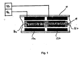
- Figure 1 shows a schematic view of part of a motor section of a borehole tool according to a first embodiment of the invention
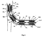
- Figure 2 shows a schematic view of a second embodiment of the invention.
- FIG. 1 shows a schematic view of part of a motor section of a borehole tool such as a drilling tool for drilling lateral boreholes.
- the motor comprises a cylindrical housing 10 of normal size for placement in a borehole.
- Stator windings 12a, 12b are provided inside the housing 10, spaced apart in the axial direction.
- An output shaft 14 is mounted for rotation inside the housing so as to be coaxial with the stators 12a, 12b.
- Rotors 16a, 16b are mounted on the output shaft 14 and positioned to align with the stator windings 12a, 12b so as to define motor sub-units.
- Each sub-unit is connected to a respective power supply and control system 18a, 18b.
- motor sub-unit is formed from stators and rotors of the type used in conventional motors for borehole tools.
- motors are commonly synchronous brushless motors which are preferred for their great power density and high reliability, but other forms of motor such as asynchronous AC motors and DC motors can also be used.
- the torque from the stacked motor is multiplied by the number of sub-units stacked together, compared to a standard electrical motor composed of one rotor and one stator (i.e. one sub-unit).
- a standard electrical motor composed of one rotor and one stator (i.e. one sub-unit).
- the entire motor assembly can be treated as a single motor and the control systems 18a, 18b operated so that the phase of each motor is driven together.
- FIG. 2 shows a schematic view of an embodiment of this approach used to power a drilling tool that is used to drill a lateral borehole 6 being drilled from a main borehole 8.
- each motor sub-unit 20a-d comprises a housing 22a-d having a stator winding 24a-d disposed therein and a shaft 26a-d on which is mounted a rotor 28a-d.
- Each sub unit 20a-d is connected to its own power supply and control system 30a-d.
- Articulated joints 32a-c are used to connect the shafts 26 of adjacent motor sub-units 20 and to transmit torque, articulated housings 34a-c being provided around the joints 32a-c.
- the shaft 26d of the final motor sub-unit 20d is connected to a drilling tool (not shown).
- the articulated joints 32a-c There are two possibilities for the articulated joints 32a-c: homocinetic couplings or non-homocinetic couplings.
- homocinetic couplings e.g. two universal joints
- non-homocinetic couplings e.g. flexible joints
- the instantaneous angle of the rotor and its stator is not considered as identical for every motor sub-unit 20.
- each motor sub-unit 20a-d is controlled independently to obtain optimal efficiency for the entire assembly.
- One such approach is to fix a target speed for the output shaft of the assembly (i.e. shaft 26d) and to provide equal current to each motor sub-unit 20a-d of the assembly so that each provides its nominal power, and the assembly will be used at its optimal efficiency.
- this option provides built-in redundancy for the system. If a motor sub-unit fails, the motor failure will be detected by its control system and this single motor sub-unit can be disconnected from its drive electronics, leaving the rest of the assembly working on its own.
- the large number of stators provides the opportunity to recombine stator windings in a homocinetic system in a large variety of configuration (Star vs. Delta, Series vs. Parallel) and consequently modify the characteristics of the assembled stacked motor as a mechanical gearbox would do.
- This 'electrical' gearbox does not require any mechanical parts.
- the gearbox ratio can be modified electrically downhole by rearranging the windings in a different pattern.
- the control system can be arranged to provide active or passive load sharing by means of open or closed loop control.
Landscapes
- Engineering & Computer Science (AREA)
- Mining & Mineral Resources (AREA)
- Geology (AREA)
- Mechanical Engineering (AREA)
- Life Sciences & Earth Sciences (AREA)
- General Engineering & Computer Science (AREA)
- Environmental & Geological Engineering (AREA)
- General Life Sciences & Earth Sciences (AREA)
- Geochemistry & Mineralogy (AREA)
- Physics & Mathematics (AREA)
- Power Engineering (AREA)
- Fluid Mechanics (AREA)
- Connection Of Motors, Electrical Generators, Mechanical Devices, And The Like (AREA)
- Iron Core Of Rotating Electric Machines (AREA)
- Electric Propulsion And Braking For Vehicles (AREA)
- Turning (AREA)
- Windings For Motors And Generators (AREA)
- Control Of Throttle Valves Provided In The Intake System Or In The Exhaust System (AREA)
- Devices For Conveying Motion By Means Of Endless Flexible Members (AREA)
- Valve Device For Special Equipments (AREA)
Abstract
Description
- This invention relates to electric motors and specifically to their use in downhole tools such as are used in exploration and production of hydrocarbons.
- Electric motors are widely used in downhole equipment in the hydrocarbon exploration and production industries. Such motors can be powered via cable from the surface, downhole generators powered by fluid flow, or batteries. A significant limitation concerning the use of electric motors is the limited diameter (OD) available for them to be fitted into downhole equipment, and consequently their limited volume. Current electric motor technology therefore provides a limit to the maximum power that can be provided within this limited volume. There are also thermal limitations for electric motors, the cooling capability mostly being proportional to the external surface of the stator (convection with the well fluid is often the predominant mechanism for heat transfer). Consequently for a given rating of motor, its possible power loss is proportional to its length; at a first order (constant efficiency), this means that the possible mechanical power of such an electric motor is also proportional to its length.
- For conventional electric motors used in the oilfield industries (the rotor being internal and the stator being wound internally), winding becomes very challenging when the length of the stator exceeds three times its OD. This means that most such long motors are hand-built as proper production tooling often does not exist to produce such designs. This can result in difficulty in ensuring a proper manufacturing process and for proper inspection of the inner winding for a long stator.
US 6288470 (CAMCO INT) 11.09.2001 discloses a modular stator for use in an electric motor. The modular stator includes a plurality of stator sections and a plurality of connectors. The plurality of stator sections have conductors extending therethrough with exposed terminal ends. The connectors have corresponding conductive elements with receptacles for receiving the terminal ends. Thus, a given stator may be assembled to a variety of desired lengths by connecting the appropriate number of modular components.US 6388353 (CAMCO INT) 14.05.2002 discloses a permanent magnet AC synchronous motor having an elongated housing, of the type used in progressive cavity pumping applications. Within the stator, a multi-section rotor is rotatably mounted. The rotor includes a plurality of rotor sections that are angularly offset from each other. The rotor sections are mounted on a drive shaft, and the sum of the offsets is generally comparable to the angular displacement undergone by the drive shaft under a normal operating load. - An objective of this invention is to provide an electric motor with increased power rating for a given OD. This objective is achieved by providing a motor with multiple, independently controllable stators that are coupled together
- A first aspect of the invention comprises an electric motor for use in a borehole tool, comprising
- a housing;
- a plurality of stator windings spaced along the inside of the housing;
- an output shaft located in the housing;
- a plurality of rotors disposed on the output shaft and aligned with the stators so as to define a plurality of motor sub-units; and
- separate power supplies and control systems for each motor sub-unit; wherein each motor sub-unit is separately controllable by means of its associated power supply and control system.
- In one embodiment, the output shaft comprises a single shaft with the rotors disposed thereon.
- In another embodiment, the output shaft comprises a plurality of sub-shafts connected end to end. In this case, each rotor can be disposed on an associated sub-shaft. The sub-shafts can connected by means of articulated connections, and the housing can be articulated in the region of the connections.
- In one preferred embodiment, the sub-shafts are connected by means of homocinetic couplings such that the instantaneous angle between the rotor and its associated stator is substantially identical for each motor sub-unit. The control systems are typically arranged to drive the phases of the motor sub-units together.
- The stator windings can be provided in a variety of configurations and the control system arranged to address the stators so as to modify the characteristics of the motor.
- In another preferred embodiment, the sub-shafts are connected by non-homocinetic couplings such that the instantaneous angle between each rotor and its associated stator is independent of those of the neighbouring motor sub-units to which it is connected. The control systems are typically arranged to drive the phases of each motor sub-units independently.
- Another aspect of the invention provides borehole tool comprising an electric motor according to the first aspect of the invention.
- Figure 1 shows a schematic view of part of a motor section of a borehole tool according to a first embodiment of the invention; and
Figure 2 shows a schematic view of a second embodiment of the invention. - Figure 1 shows a schematic view of part of a motor section of a borehole tool such as a drilling tool for drilling lateral boreholes. The motor comprises a cylindrical housing 10 of normal size for placement in a borehole.
Stator windings 12a, 12b are provided inside the housing 10, spaced apart in the axial direction. Anoutput shaft 14 is mounted for rotation inside the housing so as to be coaxial with thestators 12a, 12b. Rotors 16a, 16b are mounted on theoutput shaft 14 and positioned to align with thestator windings 12a, 12b so as to define motor sub-units. Each sub-unit is connected to a respective power supply and control system 18a, 18b. One particularly preferred form of motor sub-unit is formed from stators and rotors of the type used in conventional motors for borehole tools. Such motors are commonly synchronous brushless motors which are preferred for their great power density and high reliability, but other forms of motor such as asynchronous AC motors and DC motors can also be used. - By 'stacking' the motor sub-units, the torque from the stacked motor is multiplied by the number of sub-units stacked together, compared to a standard electrical motor composed of one rotor and one stator (i.e. one sub-unit). Thus an improved torque performance can be obtained for a given tool OD using essentially standard motor components.
- Because the rotors 16a, 16b are mounted on a single shaft, the instantaneous speed of each rotor is the same, and the instantaneous angle between the rotor and its associated stator is identical on every motor sub-unit. Therefore, the entire motor assembly can be treated as a single motor and the control systems 18a, 18b operated so that the phase of each motor is driven together.
- Proper mounting of the rotor in the stack of stators is important. For larger multiples of sub-units, manufacturing of the rotors on the shaft can become more complex in order to achieve the necessary clearance to be fitted into a stack of stators. Therefore, in another embodiment of the invention, multiple motor sub-units are coupled together, rather than using a single rotor. Figure 2 shows a schematic view of an embodiment of this approach used to power a drilling tool that is used to drill a lateral borehole 6 being drilled from a main borehole 8.
- In the embodiment of Figure 2, each motor sub-unit 20a-d comprises a housing 22a-d having a stator winding 24a-d disposed therein and a shaft 26a-d on which is mounted a rotor 28a-d. Each sub unit 20a-d is connected to its own power supply and control system 30a-d.
- Articulated joints 32a-c are used to connect the shafts 26 of adjacent motor sub-units 20 and to transmit torque, articulated housings 34a-c being provided around the joints 32a-c.
- The shaft 26d of the
final motor sub-unit 20d is connected to a drilling tool (not shown). - There are two possibilities for the articulated joints 32a-c: homocinetic couplings or non-homocinetic couplings. In homocinetic couplings (e.g. two universal joints) the tool behaves essentially in the same way as the embodiment of Figure 1 described above and can be controlled in a likewise manner. In non-homocinetic couplings (e.g. flexible joints), the instantaneous angle of the rotor and its stator is not considered as identical for every motor sub-unit 20. In this case, each motor sub-unit 20a-d is controlled independently to obtain optimal efficiency for the entire assembly. One such approach is to fix a target speed for the output shaft of the assembly (i.e. shaft 26d) and to provide equal current to each motor sub-unit 20a-d of the assembly so that each provides its nominal power, and the assembly will be used at its optimal efficiency.
- As the motor phases are driven separately in this scenario, this option provides built-in redundancy for the system. If a motor sub-unit fails, the motor failure will be detected by its control system and this single motor sub-unit can be disconnected from its drive electronics, leaving the rest of the assembly working on its own.
- The large number of stators provides the opportunity to recombine stator windings in a homocinetic system in a large variety of configuration (Star vs. Delta, Series vs. Parallel) and consequently modify the characteristics of the assembled stacked motor as a mechanical gearbox would do. This 'electrical' gearbox does not require any mechanical parts. The gearbox ratio can be modified electrically downhole by rearranging the windings in a different pattern.
- The control system can be arranged to provide active or passive load sharing by means of open or closed loop control.
- Other changes can be made while staying within the scope of the invention.
Claims (12)
- An electric motor for use in a borehole tool, comprising- a housing;- a plurality of stator windings spaced along the inside of the housing;- an output shaft located in the housing;- a plurality of rotors disposed on the output shaft and aligned with the stators so as to define a plurality of motor sub-units; and- separate power supplies and control systems for each motor sub-unit; wherein each motor sub-unit is separately controllable by means of its associated power supply and control system.
- An electric motor as claimed in claim 1, wherein the output shaft comprises a single shaft with the rotors disposed thereon.
- An electric motor as claimed in claim 1, wherein the output shaft comprises a plurality of sub-shafts connected end to end.
- An electric motor as claimed in claim 3, wherein each rotor is disposed on an associated sub-shaft.
- An electric motor as claimed in claim 3 or 4, wherein the sub-shafts are connected by means of articulated connections.
- An electric motor as claimed in claim 5, wherein the housing is articulated in the region of the connections.
- An electric motor as claimed in claim 5 or 6, wherein the sub-shafts are connected by means of homocinetic couplings such that the instantaneous angle between the rotor and its associated stator is substantially identical for each motor sub-unit.
- An electric motor as claimed in claim 7, wherein the control systems are arranged to drive the phases of the motor sub-units together.
- An electric motor as claimed in claim 7 or 8, wherein the stator windings are provided in a variety of configurations and the control system is arranged to address the stators so as to modify the characteristics of the motor.
- An electric motor as claimed in claim 5 or 6, wherein the sub-shafts are connected by non-homocinetic couplings such that the instantaneous angle between each rotor and its associated stator is independent of those of the neighbouring motor sub-units to which it is connected.
- An electric motor as claimed in claim 10, wherein the control systems are arranged to drive the phases of each motor sub-units independently.
- A borehole tool comprising an electric motor as claimed in any preceding claim.
Priority Applications (5)
| Application Number | Priority Date | Filing Date | Title |
|---|---|---|---|
| EP06291451A EP1901417B1 (en) | 2006-09-13 | 2006-09-13 | Electric motor |
| AT06291451T ATE505840T1 (en) | 2006-09-13 | 2006-09-13 | ELECTRIC MOTOR |
| DE602006021308T DE602006021308D1 (en) | 2006-09-13 | 2006-09-13 | Electric engine |
| US11/854,370 US20080061647A1 (en) | 2006-09-13 | 2007-09-12 | Electronic Motor |
| RU2007134115/09A RU2007134115A (en) | 2006-09-13 | 2007-09-12 | ELECTRICAL ENGINE |
Applications Claiming Priority (1)
| Application Number | Priority Date | Filing Date | Title |
|---|---|---|---|
| EP06291451A EP1901417B1 (en) | 2006-09-13 | 2006-09-13 | Electric motor |
Publications (2)
| Publication Number | Publication Date |
|---|---|
| EP1901417A1 true EP1901417A1 (en) | 2008-03-19 |
| EP1901417B1 EP1901417B1 (en) | 2011-04-13 |
Family
ID=37685839
Family Applications (1)
| Application Number | Title | Priority Date | Filing Date |
|---|---|---|---|
| EP06291451A Not-in-force EP1901417B1 (en) | 2006-09-13 | 2006-09-13 | Electric motor |
Country Status (5)
| Country | Link |
|---|---|
| US (1) | US20080061647A1 (en) |
| EP (1) | EP1901417B1 (en) |
| AT (1) | ATE505840T1 (en) |
| DE (1) | DE602006021308D1 (en) |
| RU (1) | RU2007134115A (en) |
Cited By (2)
| Publication number | Priority date | Publication date | Assignee | Title |
|---|---|---|---|---|
| WO2009047729A3 (en) * | 2007-10-12 | 2009-06-04 | Schlumberger Ca Ltd | Downhole load sharing motor assembly |
| WO2011074972A1 (en) * | 2009-12-16 | 2011-06-23 | Smartmotor As | System for driving elongated electric machines |
Families Citing this family (16)
| Publication number | Priority date | Publication date | Assignee | Title |
|---|---|---|---|---|
| US6464003B2 (en) * | 2000-05-18 | 2002-10-15 | Western Well Tool, Inc. | Gripper assembly for downhole tractors |
| US8245796B2 (en) * | 2000-12-01 | 2012-08-21 | Wwt International, Inc. | Tractor with improved valve system |
| US7583063B2 (en) * | 2003-05-27 | 2009-09-01 | Pratt & Whitney Canada Corp. | Architecture for electric machine |
| WO2005090739A1 (en) * | 2004-03-17 | 2005-09-29 | Western Well Tool, Inc. | Roller link toggle gripper for downhole tractor |
| US7624808B2 (en) | 2006-03-13 | 2009-12-01 | Western Well Tool, Inc. | Expandable ramp gripper |
| CA2669151C (en) * | 2006-11-14 | 2013-05-14 | Rudolph Ernst Krueger V | Variable linkage assisted gripper |
| US20100283347A1 (en) * | 2009-05-07 | 2010-11-11 | Clynton Caines | Novel ganged alternating current generator |
| US8485278B2 (en) * | 2009-09-29 | 2013-07-16 | Wwt International, Inc. | Methods and apparatuses for inhibiting rotational misalignment of assemblies in expandable well tools |
| EP2479871B1 (en) * | 2011-01-19 | 2016-06-15 | GE Energy Power Conversion Technology Limited | Electrical machines |
| CN102199989B (en) * | 2011-03-08 | 2013-06-19 | 王学明 | Automatic drilling machine without drill rod |
| US9447648B2 (en) | 2011-10-28 | 2016-09-20 | Wwt North America Holdings, Inc | High expansion or dual link gripper |
| NO334163B1 (en) * | 2012-03-30 | 2013-12-23 | Techni Holding As | Torsjonskompensator |
| US9255474B2 (en) | 2012-07-09 | 2016-02-09 | Baker Hughes Incorporated | Flexibility of downhole fluid analyzer pump module |
| US9488020B2 (en) | 2014-01-27 | 2016-11-08 | Wwt North America Holdings, Inc. | Eccentric linkage gripper |
| US11601027B2 (en) * | 2018-10-31 | 2023-03-07 | Rlt Holdings, Llc | Methods and systems for permanent magnet motors powering electric submersible pumps |
| US11962193B2 (en) * | 2019-09-17 | 2024-04-16 | Rlt Holdings, Llc | Rotor system for permanent magnet motors powering electric submersible pumps |
Citations (3)
| Publication number | Priority date | Publication date | Assignee | Title |
|---|---|---|---|---|
| US4227584A (en) * | 1978-12-19 | 1980-10-14 | Driver W B | Downhole flexible drive system |
| US20030116323A1 (en) * | 2001-12-26 | 2003-06-26 | Dana Robert Pettigrew | System for, and a method of pumping fluids from a well |
| WO2004114498A2 (en) * | 2003-06-21 | 2004-12-29 | Weatherford/Lamb, Inc. | Electric submersible pumps |
Family Cites Families (22)
| Publication number | Priority date | Publication date | Assignee | Title |
|---|---|---|---|---|
| GB956594A (en) * | 1960-04-27 | 1964-04-29 | Vismara Francesco Spa | Bis-(ª-hydroxy-ª-arylaminoacetyl)-aryl derivatives |
| US3326008A (en) * | 1965-04-01 | 1967-06-20 | Baran Paul | Electrical gopher |
| US4143722A (en) * | 1977-08-25 | 1979-03-13 | Driver W B | Downhole flexible drive system |
| US4880067A (en) * | 1988-02-17 | 1989-11-14 | Baroid Technology, Inc. | Apparatus for drilling a curved borehole |
| JPH0815377B2 (en) * | 1989-10-05 | 1996-02-14 | 株式会社佐竹製作所 | Two-stator three-phase squirrel-cage induction motor |
| US5210381A (en) * | 1991-05-23 | 1993-05-11 | Oil And Gas Consultants International, Inc. | Apparatus for generating vibrational energy in a borehole |
| US5727641A (en) * | 1994-11-01 | 1998-03-17 | Schlumberger Technology Corporation | Articulated directional drilling motor assembly |
| TW396673B (en) * | 1995-12-22 | 2000-07-01 | Satake Eng Co Ltd | Induction motor driving device and the method for its starting operation |
| US6288470B1 (en) * | 1999-02-11 | 2001-09-11 | Camco International, Inc. | Modular motor construction |
| US6388353B1 (en) * | 2000-03-30 | 2002-05-14 | Camco International, Inc. | Elongated permanent magnet synchronous motor |
| US6364038B1 (en) * | 2000-04-21 | 2002-04-02 | W B Driver | Downhole flexible drive system |
| US6439325B1 (en) * | 2000-07-19 | 2002-08-27 | Baker Hughes Incorporated | Drilling apparatus with motor-driven pump steering control |
| US6509703B1 (en) * | 2000-11-28 | 2003-01-21 | Husky Injection Molding Systems, Ltd. | Method and system for reduced voltage start-up of AC motors in multi-motor system |
| JP4722309B2 (en) * | 2000-12-27 | 2011-07-13 | 三菱電機株式会社 | Rotating electric machine and pulley drive device using the rotating electric machine |
| US6484801B2 (en) * | 2001-03-16 | 2002-11-26 | Baker Hughes Incorporated | Flexible joint for well logging instruments |
| DE10230253A1 (en) * | 2002-07-04 | 2004-01-22 | Behr Gmbh & Co. | Arrangement and method for protection against overload of an electric motor |
| CA2630120C (en) * | 2002-09-18 | 2011-04-19 | Artificial Lift Company Limited | Electric motors for powering downhole tools |
| US7055627B2 (en) * | 2002-11-22 | 2006-06-06 | Baker Hughes Incorporated | Wellbore fluid circulation system and method |
| GB0314550D0 (en) * | 2003-06-21 | 2003-07-30 | Weatherford Lamb | Electric submersible pumps |
| US6964299B2 (en) * | 2003-08-13 | 2005-11-15 | Schlumberger Technology Corporation | Submersible pumping system |
| US7038423B2 (en) * | 2004-05-07 | 2006-05-02 | Bay Controls, Inc. | Apparatus and method for ride through for AC induction motors |
| JP4783012B2 (en) * | 2004-12-28 | 2011-09-28 | 日立オートモティブシステムズ株式会社 | Electric power steering motor and manufacturing method thereof |
-
2006
- 2006-09-13 AT AT06291451T patent/ATE505840T1/en not_active IP Right Cessation
- 2006-09-13 DE DE602006021308T patent/DE602006021308D1/en active Active
- 2006-09-13 EP EP06291451A patent/EP1901417B1/en not_active Not-in-force
-
2007
- 2007-09-12 US US11/854,370 patent/US20080061647A1/en not_active Abandoned
- 2007-09-12 RU RU2007134115/09A patent/RU2007134115A/en not_active Application Discontinuation
Patent Citations (3)
| Publication number | Priority date | Publication date | Assignee | Title |
|---|---|---|---|---|
| US4227584A (en) * | 1978-12-19 | 1980-10-14 | Driver W B | Downhole flexible drive system |
| US20030116323A1 (en) * | 2001-12-26 | 2003-06-26 | Dana Robert Pettigrew | System for, and a method of pumping fluids from a well |
| WO2004114498A2 (en) * | 2003-06-21 | 2004-12-29 | Weatherford/Lamb, Inc. | Electric submersible pumps |
Cited By (5)
| Publication number | Priority date | Publication date | Assignee | Title |
|---|---|---|---|---|
| WO2009047729A3 (en) * | 2007-10-12 | 2009-06-04 | Schlumberger Ca Ltd | Downhole load sharing motor assembly |
| GB2466408A (en) * | 2007-10-12 | 2010-06-23 | Schlumberger Holdings | Downhole load sharing motor assembly |
| WO2011074972A1 (en) * | 2009-12-16 | 2011-06-23 | Smartmotor As | System for driving elongated electric machines |
| NO332768B1 (en) * | 2009-12-16 | 2013-01-14 | Smartmotor As | System for operation of elongated electric machines |
| US8866425B2 (en) | 2009-12-16 | 2014-10-21 | Smartmotor As | System for driving elongated electric machines |
Also Published As
| Publication number | Publication date |
|---|---|
| US20080061647A1 (en) | 2008-03-13 |
| ATE505840T1 (en) | 2011-04-15 |
| EP1901417B1 (en) | 2011-04-13 |
| RU2007134115A (en) | 2009-03-20 |
| DE602006021308D1 (en) | 2011-05-26 |
Similar Documents
| Publication | Publication Date | Title |
|---|---|---|
| US20080061647A1 (en) | Electronic Motor | |
| US6388353B1 (en) | Elongated permanent magnet synchronous motor | |
| US8353336B2 (en) | Power transmission system for use with downhole equipment | |
| US8866425B2 (en) | System for driving elongated electric machines | |
| US6700252B2 (en) | Field configurable modular motor | |
| CA2348351C (en) | Modular motor and housing | |
| US20070071612A1 (en) | Electric submersible pumps | |
| GB2439483A (en) | Synchronous motor drives | |
| CN101243600B (en) | Brushless motor commutation and control | |
| US12025136B2 (en) | Electrical submersible pumping systems | |
| CA2552227A1 (en) | Turbine generator system and method | |
| US11502583B1 (en) | Printed circuit board stator winding enhancements for axial field rotary energy device | |
| WO2007144820A2 (en) | Brushless motor commutation and control | |
| CA2530162C (en) | Electric submersible pumps | |
| CN120150459B (en) | Axial segmentation oil-submersible permanent magnet motor | |
| WO2016084219A1 (en) | Permanent magnet type rotating electrical machine, and drive system and compressor system using same | |
| US20260055687A1 (en) | Enhanced cooling of non-encapsulated motor stators for electrical submersible pumps | |
| CN109792190A (en) | Motor |
Legal Events
| Date | Code | Title | Description |
|---|---|---|---|
| PUAI | Public reference made under article 153(3) epc to a published international application that has entered the european phase |
Free format text: ORIGINAL CODE: 0009012 |
|
| AK | Designated contracting states |
Kind code of ref document: A1 Designated state(s): AT BE BG CH CY CZ DE DK EE ES FI FR GB GR HU IE IS IT LI LT LU LV MC NL PL PT RO SE SI SK TR |
|
| AX | Request for extension of the european patent |
Extension state: AL BA HR MK YU |
|
| 17P | Request for examination filed |
Effective date: 20080919 |
|
| 17Q | First examination report despatched |
Effective date: 20081024 |
|
| AKX | Designation fees paid |
Designated state(s): AT BE BG CH CY CZ DE DK EE ES FI FR GB GR HU IE IS IT LI LT LU LV MC NL PL PT RO SE SI SK TR |
|
| GRAP | Despatch of communication of intention to grant a patent |
Free format text: ORIGINAL CODE: EPIDOSNIGR1 |
|
| GRAS | Grant fee paid |
Free format text: ORIGINAL CODE: EPIDOSNIGR3 |
|
| GRAA | (expected) grant |
Free format text: ORIGINAL CODE: 0009210 |
|
| AK | Designated contracting states |
Kind code of ref document: B1 Designated state(s): AT BE BG CH CY CZ DE DK EE ES FI FR GB GR HU IE IS IT LI LT LU LV MC NL PL PT RO SE SI SK TR |
|
| REG | Reference to a national code |
Ref country code: GB Ref legal event code: FG4D |
|
| REG | Reference to a national code |
Ref country code: CH Ref legal event code: EP |
|
| REG | Reference to a national code |
Ref country code: IE Ref legal event code: FG4D |
|
| REF | Corresponds to: |
Ref document number: 602006021308 Country of ref document: DE Date of ref document: 20110526 Kind code of ref document: P |
|
| REG | Reference to a national code |
Ref country code: DE Ref legal event code: R096 Ref document number: 602006021308 Country of ref document: DE Effective date: 20110526 |
|
| REG | Reference to a national code |
Ref country code: NL Ref legal event code: VDEP Effective date: 20110413 |
|
| LTIE | Lt: invalidation of european patent or patent extension |
Effective date: 20110413 |
|
| PG25 | Lapsed in a contracting state [announced via postgrant information from national office to epo] |
Ref country code: SE Free format text: LAPSE BECAUSE OF FAILURE TO SUBMIT A TRANSLATION OF THE DESCRIPTION OR TO PAY THE FEE WITHIN THE PRESCRIBED TIME-LIMIT Effective date: 20110413 Ref country code: LT Free format text: LAPSE BECAUSE OF FAILURE TO SUBMIT A TRANSLATION OF THE DESCRIPTION OR TO PAY THE FEE WITHIN THE PRESCRIBED TIME-LIMIT Effective date: 20110413 Ref country code: PT Free format text: LAPSE BECAUSE OF FAILURE TO SUBMIT A TRANSLATION OF THE DESCRIPTION OR TO PAY THE FEE WITHIN THE PRESCRIBED TIME-LIMIT Effective date: 20110816 |
|
| PG25 | Lapsed in a contracting state [announced via postgrant information from national office to epo] |
Ref country code: BE Free format text: LAPSE BECAUSE OF FAILURE TO SUBMIT A TRANSLATION OF THE DESCRIPTION OR TO PAY THE FEE WITHIN THE PRESCRIBED TIME-LIMIT Effective date: 20110413 Ref country code: ES Free format text: LAPSE BECAUSE OF FAILURE TO SUBMIT A TRANSLATION OF THE DESCRIPTION OR TO PAY THE FEE WITHIN THE PRESCRIBED TIME-LIMIT Effective date: 20110724 Ref country code: FI Free format text: LAPSE BECAUSE OF FAILURE TO SUBMIT A TRANSLATION OF THE DESCRIPTION OR TO PAY THE FEE WITHIN THE PRESCRIBED TIME-LIMIT Effective date: 20110413 Ref country code: GR Free format text: LAPSE BECAUSE OF FAILURE TO SUBMIT A TRANSLATION OF THE DESCRIPTION OR TO PAY THE FEE WITHIN THE PRESCRIBED TIME-LIMIT Effective date: 20110714 Ref country code: AT Free format text: LAPSE BECAUSE OF FAILURE TO SUBMIT A TRANSLATION OF THE DESCRIPTION OR TO PAY THE FEE WITHIN THE PRESCRIBED TIME-LIMIT Effective date: 20110413 Ref country code: IS Free format text: LAPSE BECAUSE OF FAILURE TO SUBMIT A TRANSLATION OF THE DESCRIPTION OR TO PAY THE FEE WITHIN THE PRESCRIBED TIME-LIMIT Effective date: 20110813 Ref country code: LV Free format text: LAPSE BECAUSE OF FAILURE TO SUBMIT A TRANSLATION OF THE DESCRIPTION OR TO PAY THE FEE WITHIN THE PRESCRIBED TIME-LIMIT Effective date: 20110413 Ref country code: SI Free format text: LAPSE BECAUSE OF FAILURE TO SUBMIT A TRANSLATION OF THE DESCRIPTION OR TO PAY THE FEE WITHIN THE PRESCRIBED TIME-LIMIT Effective date: 20110413 Ref country code: CY Free format text: LAPSE BECAUSE OF FAILURE TO SUBMIT A TRANSLATION OF THE DESCRIPTION OR TO PAY THE FEE WITHIN THE PRESCRIBED TIME-LIMIT Effective date: 20110413 |
|
| PG25 | Lapsed in a contracting state [announced via postgrant information from national office to epo] |
Ref country code: NL Free format text: LAPSE BECAUSE OF FAILURE TO SUBMIT A TRANSLATION OF THE DESCRIPTION OR TO PAY THE FEE WITHIN THE PRESCRIBED TIME-LIMIT Effective date: 20110413 |
|
| PG25 | Lapsed in a contracting state [announced via postgrant information from national office to epo] |
Ref country code: CZ Free format text: LAPSE BECAUSE OF FAILURE TO SUBMIT A TRANSLATION OF THE DESCRIPTION OR TO PAY THE FEE WITHIN THE PRESCRIBED TIME-LIMIT Effective date: 20110413 Ref country code: EE Free format text: LAPSE BECAUSE OF FAILURE TO SUBMIT A TRANSLATION OF THE DESCRIPTION OR TO PAY THE FEE WITHIN THE PRESCRIBED TIME-LIMIT Effective date: 20110413 |
|
| PLBE | No opposition filed within time limit |
Free format text: ORIGINAL CODE: 0009261 |
|
| STAA | Information on the status of an ep patent application or granted ep patent |
Free format text: STATUS: NO OPPOSITION FILED WITHIN TIME LIMIT |
|
| PG25 | Lapsed in a contracting state [announced via postgrant information from national office to epo] |
Ref country code: SK Free format text: LAPSE BECAUSE OF FAILURE TO SUBMIT A TRANSLATION OF THE DESCRIPTION OR TO PAY THE FEE WITHIN THE PRESCRIBED TIME-LIMIT Effective date: 20110413 Ref country code: DK Free format text: LAPSE BECAUSE OF FAILURE TO SUBMIT A TRANSLATION OF THE DESCRIPTION OR TO PAY THE FEE WITHIN THE PRESCRIBED TIME-LIMIT Effective date: 20110413 Ref country code: PL Free format text: LAPSE BECAUSE OF FAILURE TO SUBMIT A TRANSLATION OF THE DESCRIPTION OR TO PAY THE FEE WITHIN THE PRESCRIBED TIME-LIMIT Effective date: 20110413 Ref country code: RO Free format text: LAPSE BECAUSE OF FAILURE TO SUBMIT A TRANSLATION OF THE DESCRIPTION OR TO PAY THE FEE WITHIN THE PRESCRIBED TIME-LIMIT Effective date: 20110413 |
|
| 26N | No opposition filed |
Effective date: 20120116 |
|
| PG25 | Lapsed in a contracting state [announced via postgrant information from national office to epo] |
Ref country code: MC Free format text: LAPSE BECAUSE OF NON-PAYMENT OF DUE FEES Effective date: 20110930 |
|
| REG | Reference to a national code |
Ref country code: CH Ref legal event code: PL |
|
| REG | Reference to a national code |
Ref country code: DE Ref legal event code: R097 Ref document number: 602006021308 Country of ref document: DE Effective date: 20120116 |
|
| PG25 | Lapsed in a contracting state [announced via postgrant information from national office to epo] |
Ref country code: IT Free format text: LAPSE BECAUSE OF FAILURE TO SUBMIT A TRANSLATION OF THE DESCRIPTION OR TO PAY THE FEE WITHIN THE PRESCRIBED TIME-LIMIT Effective date: 20110413 |
|
| REG | Reference to a national code |
Ref country code: IE Ref legal event code: MM4A |
|
| REG | Reference to a national code |
Ref country code: DE Ref legal event code: R119 Ref document number: 602006021308 Country of ref document: DE Effective date: 20120403 |
|
| PG25 | Lapsed in a contracting state [announced via postgrant information from national office to epo] |
Ref country code: LI Free format text: LAPSE BECAUSE OF NON-PAYMENT OF DUE FEES Effective date: 20110930 Ref country code: CH Free format text: LAPSE BECAUSE OF NON-PAYMENT OF DUE FEES Effective date: 20110930 Ref country code: IE Free format text: LAPSE BECAUSE OF NON-PAYMENT OF DUE FEES Effective date: 20110913 Ref country code: DE Free format text: LAPSE BECAUSE OF NON-PAYMENT OF DUE FEES Effective date: 20120403 |
|
| PG25 | Lapsed in a contracting state [announced via postgrant information from national office to epo] |
Ref country code: LU Free format text: LAPSE BECAUSE OF NON-PAYMENT OF DUE FEES Effective date: 20110913 |
|
| PG25 | Lapsed in a contracting state [announced via postgrant information from national office to epo] |
Ref country code: BG Free format text: LAPSE BECAUSE OF FAILURE TO SUBMIT A TRANSLATION OF THE DESCRIPTION OR TO PAY THE FEE WITHIN THE PRESCRIBED TIME-LIMIT Effective date: 20110713 |
|
| PG25 | Lapsed in a contracting state [announced via postgrant information from national office to epo] |
Ref country code: TR Free format text: LAPSE BECAUSE OF FAILURE TO SUBMIT A TRANSLATION OF THE DESCRIPTION OR TO PAY THE FEE WITHIN THE PRESCRIBED TIME-LIMIT Effective date: 20110413 |
|
| PG25 | Lapsed in a contracting state [announced via postgrant information from national office to epo] |
Ref country code: HU Free format text: LAPSE BECAUSE OF FAILURE TO SUBMIT A TRANSLATION OF THE DESCRIPTION OR TO PAY THE FEE WITHIN THE PRESCRIBED TIME-LIMIT Effective date: 20110413 |
|
| PGFP | Annual fee paid to national office [announced via postgrant information from national office to epo] |
Ref country code: FR Payment date: 20140906 Year of fee payment: 9 |
|
| REG | Reference to a national code |
Ref country code: FR Ref legal event code: ST Effective date: 20160531 |
|
| PG25 | Lapsed in a contracting state [announced via postgrant information from national office to epo] |
Ref country code: FR Free format text: LAPSE BECAUSE OF NON-PAYMENT OF DUE FEES Effective date: 20150930 |
|
| PGFP | Annual fee paid to national office [announced via postgrant information from national office to epo] |
Ref country code: GB Payment date: 20160907 Year of fee payment: 11 |
|
| GBPC | Gb: european patent ceased through non-payment of renewal fee |
Effective date: 20170913 |
|
| PG25 | Lapsed in a contracting state [announced via postgrant information from national office to epo] |
Ref country code: GB Free format text: LAPSE BECAUSE OF NON-PAYMENT OF DUE FEES Effective date: 20170913 |