EP1901413A2 - Battery management system and method - Google Patents
Battery management system and method Download PDFInfo
- Publication number
- EP1901413A2 EP1901413A2 EP07115331A EP07115331A EP1901413A2 EP 1901413 A2 EP1901413 A2 EP 1901413A2 EP 07115331 A EP07115331 A EP 07115331A EP 07115331 A EP07115331 A EP 07115331A EP 1901413 A2 EP1901413 A2 EP 1901413A2
- Authority
- EP
- European Patent Office
- Prior art keywords
- battery
- ocv
- time
- voltage
- soc
- Prior art date
- Legal status (The legal status is an assumption and is not a legal conclusion. Google has not performed a legal analysis and makes no representation as to the accuracy of the status listed.)
- Withdrawn
Links
Images


Classifications
-
- H—ELECTRICITY
- H01—ELECTRIC ELEMENTS
- H01M—PROCESSES OR MEANS, e.g. BATTERIES, FOR THE DIRECT CONVERSION OF CHEMICAL ENERGY INTO ELECTRICAL ENERGY
- H01M10/00—Secondary cells; Manufacture thereof
- H01M10/42—Methods or arrangements for servicing or maintenance of secondary cells or secondary half-cells
- H01M10/48—Accumulators combined with arrangements for measuring, testing or indicating the condition of cells, e.g. the level or density of the electrolyte
-
- G—PHYSICS
- G01—MEASURING; TESTING
- G01R—MEASURING ELECTRIC VARIABLES; MEASURING MAGNETIC VARIABLES
- G01R19/00—Arrangements for measuring currents or voltages or for indicating presence or sign thereof
- G01R19/165—Indicating that current or voltage is either above or below a predetermined value or within or outside a predetermined range of values
- G01R19/16533—Indicating that current or voltage is either above or below a predetermined value or within or outside a predetermined range of values characterised by the application
- G01R19/16538—Indicating that current or voltage is either above or below a predetermined value or within or outside a predetermined range of values characterised by the application in AC or DC supplies
- G01R19/16542—Indicating that current or voltage is either above or below a predetermined value or within or outside a predetermined range of values characterised by the application in AC or DC supplies for batteries
-
- H—ELECTRICITY
- H02—GENERATION; CONVERSION OR DISTRIBUTION OF ELECTRIC POWER
- H02J—ELECTRIC POWER NETWORKS; CIRCUIT ARRANGEMENTS OR SYSTEMS FOR SUPPLYING OR DISTRIBUTING ELECTRIC POWER; SYSTEMS FOR STORING ELECTRIC ENERGY
- H02J7/00—Circuit arrangements for charging or discharging batteries or for supplying loads from batteries
- H02J7/80—Circuit arrangements for charging or discharging batteries or for supplying loads from batteries including monitoring or indicating arrangements
- H02J7/82—Control of state of charge [SOC]
-
- G—PHYSICS
- G01—MEASURING; TESTING
- G01R—MEASURING ELECTRIC VARIABLES; MEASURING MAGNETIC VARIABLES
- G01R31/00—Arrangements for testing electric properties; Arrangements for locating electric faults; Arrangements for electrical testing characterised by what is being tested not provided for elsewhere
- G01R31/005—Testing of electric installations on transport means
-
- G—PHYSICS
- G01—MEASURING; TESTING
- G01R—MEASURING ELECTRIC VARIABLES; MEASURING MAGNETIC VARIABLES
- G01R31/00—Arrangements for testing electric properties; Arrangements for locating electric faults; Arrangements for electrical testing characterised by what is being tested not provided for elsewhere
- G01R31/36—Arrangements for testing, measuring or monitoring the electrical condition of accumulators or electric batteries, e.g. capacity or state of charge [SoC]
- G01R31/3644—Constructional arrangements
- G01R31/3648—Constructional arrangements comprising digital calculation means, e.g. for performing an algorithm
-
- H—ELECTRICITY
- H02—GENERATION; CONVERSION OR DISTRIBUTION OF ELECTRIC POWER
- H02J—ELECTRIC POWER NETWORKS; CIRCUIT ARRANGEMENTS OR SYSTEMS FOR SUPPLYING OR DISTRIBUTING ELECTRIC POWER; SYSTEMS FOR STORING ELECTRIC ENERGY
- H02J7/00—Circuit arrangements for charging or discharging batteries or for supplying loads from batteries
- H02J7/14—Circuit arrangements for charging or discharging batteries or for supplying loads from batteries for charging batteries from dynamo-electric generators driven at varying speed, e.g. on vehicle
- H02J7/1423—Circuit arrangements for charging or discharging batteries or for supplying loads from batteries for charging batteries from dynamo-electric generators driven at varying speed, e.g. on vehicle with multiple batteries
-
- H—ELECTRICITY
- H02—GENERATION; CONVERSION OR DISTRIBUTION OF ELECTRIC POWER
- H02J—ELECTRIC POWER NETWORKS; CIRCUIT ARRANGEMENTS OR SYSTEMS FOR SUPPLYING OR DISTRIBUTING ELECTRIC POWER; SYSTEMS FOR STORING ELECTRIC ENERGY
- H02J7/00—Circuit arrangements for charging or discharging batteries or for supplying loads from batteries
- H02J7/80—Circuit arrangements for charging or discharging batteries or for supplying loads from batteries including monitoring or indicating arrangements
- H02J7/84—Control of state of health [SOH]
-
- Y—GENERAL TAGGING OF NEW TECHNOLOGICAL DEVELOPMENTS; GENERAL TAGGING OF CROSS-SECTIONAL TECHNOLOGIES SPANNING OVER SEVERAL SECTIONS OF THE IPC; TECHNICAL SUBJECTS COVERED BY FORMER USPC CROSS-REFERENCE ART COLLECTIONS [XRACs] AND DIGESTS
- Y02—TECHNOLOGIES OR APPLICATIONS FOR MITIGATION OR ADAPTATION AGAINST CLIMATE CHANGE
- Y02E—REDUCTION OF GREENHOUSE GAS [GHG] EMISSIONS, RELATED TO ENERGY GENERATION, TRANSMISSION OR DISTRIBUTION
- Y02E60/00—Enabling technologies; Technologies with a potential or indirect contribution to GHG emissions mitigation
- Y02E60/10—Energy storage using batteries
Definitions
- aspects of the present invention relate to a battery management system. More particularly, aspects of the present invention relate to a battery management system used in a vehicle using electrical energy.
- An electric vehicle uses an electric motor powered by electrical energy output by a battery. Since the electric vehicle mainly uses a battery formed by one battery pack including a plurality of rechargeable/dischargeable secondary cells, advantages thereof includes no emission gases and less noise.
- a hybrid vehicle commonly refers to a petrol-electric hybrid vehicle which uses petrol to power an internal-combustion engine and a battery to power an electric motor.
- hybrid vehicles that use an internal-combustion engine and fuel cells, and hybrid vehicles that use a battery and fuel cells have been developed.
- the fuel cells directly obtain electrical energy by generating a chemical reaction while hydrogen and oxygen are continuously provided.
- BMS battery management system
- the battery management system uses a data table containing relationship data of an open circuit voltage (OCV) to a state of charge (SOC) to estimate the SOC.
- OCV open circuit voltage
- SOC state of charge
- the OCV should be precisely measured so as to precisely calculate the SOC.
- the OCV may not be precisely measured due to polarization or internal resistance of the battery.
- a time to dissipate the polarization should be sufficient to precisely measure the OCV.
- the battery since an error in controlling the battery to be charged and discharged is generated when an error in calculating the SOC occurs, the battery may be overcharged or over-discharged, which seriously affects battery performance.
- aspects of the present invention has been made in an effort to provide a battery management system to more precisely estimate an open circuit voltage (OCV) and to establish a state of charge (SOC), and a driving method thereof.
- OCV open circuit voltage
- SOC state of charge
- a battery management system used to establish a state of charge (SOC) of a battery used in the battery management system includes a sensing unit and a micro control unit (MCU).
- the sensing unit measures a battery voltage
- the MCU measures a first time and a second time, detects first and second battery voltages that respectively correspond to the first and second times from the battery voltage, estimates an open circuit voltage (OCV) by the first and second voltages, and determines the SOC that corresponds to the OCV.
- the first time is a time when an effect of an internal resistance of the battery is eliminated
- the second time is a time after a predetermined period has passed from the first time to dissipate polarization caused by electrolyte diffusion.
- the MCU includes an OCV estimator and an SOC establishment unit.
- the OCV estimator estimates the OCV by using the first and second voltages, while the SOC establishment unit receives the OCV and establishes the SOC that corresponds to the OCV.
- the method includes: when the battery is not charged and discharged, a first time and a second time are measured, and a first battery voltage that corresponds to the first time and a second battery voltage that corresponds to the second time are detected; generating a linear equation having the first time, the first battery voltage, the second time, and the second battery voltage is generated; and an open circuit voltage (OCV) is estimated by using the linear equation.
- SOC state of charge
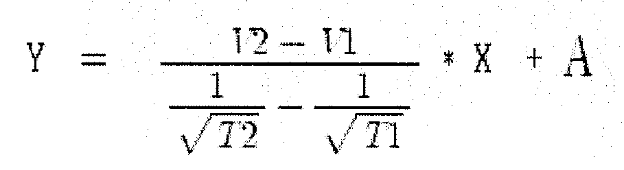
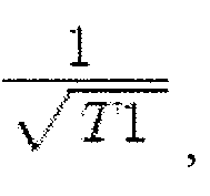
- the linear equation given as Y V ⁇ 2 - V ⁇ 1 1 T ⁇ 2 - 1 T ⁇ 1 * X + A (where, X denotes a parameter in 1 T ⁇ 1 , and Y denotes a parameter in voltage) is generated from a graph or slope that passes through coordinates 1 T ⁇ 1 ⁇ , V ⁇ 1 that correspond to the first time, and coordinates 1 T ⁇ 2 ⁇ , V ⁇ 2 that correspond to the second time, and a value of a Y-axis coordinate when an X-axis coordinate value is 0 is estimated as the OCV.
- the estimated OCV is received, a table for the SOC that corresponds to the OCV is used, and the SOC is established.
- a driving method of a battery management system to obtain a state of charge (SOC) of a rechargeable battery includes: measuring at least one time; detecting at least one voltage of the rechargeable battery that corresponds to the at least one time; determining an open circuit voltage (OCV) of the rechargeable battery based on the at least one time and the at least one voltage; and determining the SOC of the rechargeable battery that corresponds to the determined OCV.
- SOC state of charge
- a method to obtain a state of charge (SOC) of a rechargeable battery includes: detecting voltage of the rechargeable battery corresponding to time; determining an open circuit voltage (OCV) of the rechargeable battery using an inverse relationship of the time relative to the voltage; and determining the SOC of the rechargeable battery that corresponds to the determined OCV.
- SOC state of charge
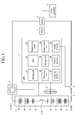
- FIG. 1 shows a diagram of a configuration of a hybrid vehicle system according to an aspect of the present invention.
- the hybrid electric vehicle system includes a battery management system 1, a battery 2, a current sensor 3, a cooling fan 4, a fuse 5, a main switch 6, a motor control unit (MTCU) 7, an inverter 8, and a motor generator 9.
- a battery management system 1 a battery 2
- a current sensor 3 a current sensor 3
- a cooling fan 4 a fuse 5
- main switch 6 a motor control unit (MTCU) 7, an inverter 8
- MTCU motor control unit
- the battery 2 includes a plurality of sub-packs 2a to 2h having a plurality of battery cells coupled in series to each other, an output terminal 2_OUT1, an output terminal 2_OUT2, and a safety switch 2_SW provided between the sub-pack 2d and the sub-pack 2e. While eight sub-packs 2a to 2h are shown as an example and each sub-pack is a group of a plurality of battery cells, aspects of the present invention are not limited thereto.
- the safety switch 2_SW is selectively turned on/off to guarantee the safety of a worker when performing operations on the battery or replacing the battery.
- the safety switch 2_SW is provided between the sub-pack 2d and the sub-pack 2e.
- the output terminal 2_OUT1 and the output terminal 2_OUT2 are coupled, for example, to the inverter 8.
- the current sensor 3 measures an output current value of the battery 2 and outputs the measured output current value to a sensing unit 10 of the BMS 1.
- the current sensor 3 may be a Hall current transformer using a Hall element to measure a current value and to output an analog current signal that corresponds to the measured current value.
- other types of current sensors are within the scope of the invention.
- the cooling fan 4 cools down heat generated by charging and discharging of the battery 2 in response to a control signal of the BMS 1, prevents the battery 2 from being deteriorated by a temperature increase, and prevents the charging and discharging efficiencies of the battery 2 from being deteriorated.
- the fuse 5 prevents an overcurrent, which may be caused by a disconnection or a short circuit of the battery 2, from being transmitted to the battery 2. That is, when an overcurrent is generated, the fuse 5 is disconnected to interrupt the current from overflowing and to isolate the battery 2 from the overcurrent.
- the main switch 6 turns on/off the battery in response to the control signal of the BMS 1 or a control signal of the MTCU 7 when an unusual phenomenon, such as an overvoltage, overcurrent, and/or overheating (a high temperature), occurs.
- an unusual phenomenon such as an overvoltage, overcurrent, and/or overheating (a high temperature)
- the BMS 1 includes a sensing unit 10, a micro control unit (MCU) 20, an internal power supply 30, a cell balance unit 40, a storage unit 50, a communication unit 60, a protection circuit unit 70, a power-on reset unit 80, and an external interface 90.
- the sensing unit 10 measures a voltage of the battery and transmits the sensed voltage to the MCU 20.
- a voltage at an output terminal of the battery will be referred to as a battery voltage.
- the MCU 20 detects a state of charge (SOC) of the battery 2 based on the battery voltage transmitted from the sensing unit 10, and generates information that informs of a state of the battery 2. Then, the MCU 20 transmits the generated information to the MTCU 7 of the vehicle. In addition, when the vehicle is stopped or driven at a fixed speed and the battery is not charged and discharged, the MCU 20 detects a first voltage V1 of a first time T1 and a second voltage V2 of a second time T2 to generate an equation, such as a linear equation (or a line equation). The MCU 20 uses the linear equation to estimate an open circuit voltage (OCV), and establishes (or estimates) the SOC that corresponds to the estimated OCV.
- OCV open circuit voltage
- the internal power supply 30 supplies power to the BMS 1 by using a backup battery.
- the cell balance unit 40 balances the state of charge of each cell. That is, cells sufficiently charged are discharged, and cells relatively less charged are further charged.
- the storage unit 50 stores data of the current SOC and a current state of health (SOH) of the battery when the power source of the BMS 1 is turned off.
- the communication unit 60 communicates with the MTCU 7 of the vehicle.
- the protection circuit unit 70 uses firmware to protect the battery 2 from shocks, overcurrents, low voltages, and/or the like.
- the power-on reset unit 80 resets the overall system when the power source of the BMS 1 is turned on.
- the external interface 90 couples BMS auxiliary devices, such as the cooling fan 4 and the main switch 6, to the MCU 20. While the cooling fan 4 and the main switch 6 are shown as the BMS auxiliary devices as examples, aspects of the present invention are not limited thereto.
- the MTCU 7 determines a torque state (or information) of the vehicle based on information of an accelerator, a brake, and a vehicle speed, and controls an output of the motor generator 9 so that the output corresponds to the torque state (or information). That is, the MTCU 7 controls a switching operation of the inverter 8, and controls the output of the motor generator 9 so that the output corresponds to the torque state and/or its information.
- the MTCU 7 receives the SOC of the battery 2 from the MCU 20 through the communication unit 60, and controls the SOC level of the battery 2 to be a target level (e.g., 55%).
- the MTCU 7 controls a switch of the inverter 8 to output power toward the battery 2 and charge the battery 2.
- the battery pack current (I) has a negative value (-).
- the MTCU 7 controls the switch of the inverter 8 to output the power toward the motor generator 9 and discharge the battery 2.
- the battery pack current (I) has a positive value (+). It is understood that the target level of the SOC to charge and/or discharge the battery may be any value.
- the inverter 8 controls the battery 2 to be charged and/or discharged in response to the control signal of the MTCU 7.
- the motor generator 9 uses the electrical energy of the battery to drive the vehicle based on the torque information transmitted from the MTCU 7.
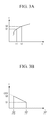
- FIG. 2 shows a schematic diagram of the MCU 20 of the battery management system as shown in FIG. 1, and FIGS. 3A and 3B show diagrams representing a relationship between times and battery voltages.
- the MCU 20 includes an OCV estimator 210, a data storage unit 230, and an SOC establishment unit 220.
- the OCV estimator 210 detects a battery voltage at the first time T1 and a battery voltage at the second time T2 using the battery voltage input from the sensing unit 10.
- the first time T1 corresponds to a time when the effect caused by internal resistance of the battery 2 is eliminated.
- the second time T2 corresponds to a time when a predetermined time passes from the time of solving (or dissipating) the polarization caused by electrolyte diffusion, after the effect of the resistance caused by the internal resistance is eliminated.
- the above times may be experimentally established.
- the times T1 and/or the T2 may simply be set and/or predetermined.
- the OCV estimator 210 uses the detected first battery voltage V1 and second battery voltage V2 to estimate the OCV, as discussed below.
- FIGS. 3A and 3B show diagrams representing a relationship between time and battery voltages according to aspects of the present invention.
- the OCV estimator 210 detects the first battery voltage V1 at the first time T1, and the second battery voltage V2 at the second time T2 after the predetermined time passes from the first time T1.
- the OCV estimator 210 takes the detected voltage-time information as represented by FIG. 3A and determines or obtains the voltage-time information as represented by a linear graph shown in FIG. 3B.
- the polarization is solved (or dissipated) and the battery voltage is stabilized as the time t passes.
- the time t is ideally unlimited (or approaches infinity)
- the polarization is completely solved (or dissipated), and the OCV may be precisely detected.
- the MCU 20 generates the linear equation (or the line equation) as discussed above.
- the OCV estimator 210 uses the linear equation and may estimate the OCV at an unlimited time (at infinity, for example). In this case, to detect (or estimate) the OCV at the time the battery is most stable, the OCV estimator 210 changes the graph shown in FIG. 3A to the graph shown in FIG. 3B. Accordingly, a line that passes through coordinates 1 T ⁇ 1 ⁇ , V ⁇ 1 that correspond to the first time T1 and coordinates 1 T ⁇ 2 ⁇ , V ⁇ 2 that correspond to the second time T2, are used so as to generate the linear equation. In FIG.
- X-axis coordinates have a parameter of 1 T and Y-axis coordinates have a parameter of the battery voltage (v). That is, in various aspects of the present invention, the battery voltage is inversely proportional to the square root of the time.
- the OCV estimator 210 uses Equation 1 and coordinates that correspond to the first and second times T1 and T2 to detect a value of a slope (a) in the linear graph shown in FIG. 3B, as shown below.
- a V ⁇ 2 + V ⁇ 1 1 T ⁇ 2 - 1 T ⁇ 1
- the OCV estimator 210 generates a linear equation (or a line equation) given as Equation 2 in the graph having the slope (a), and as shown in FIG. 3B, and as discussed below.
- Y V ⁇ 2 - V ⁇ 1 1 T ⁇ 2 - 1 T ⁇ 1 * X + A
- X denotes a parameter in 1 T which is obtained by converting from the time t
- Y denotes a parameter in voltage (v).
- the OCV estimator 210 when the time t goes to infinity as shown in FIG. 3B, a voltage value that corresponds to the Y-axis coordinate value becomes the open circuit voltage (OCV).
- OCV open circuit voltage
- a value of the Y-axis coordinate is estimated (or extrapolated) as the OCV when an X-axis coordinate value is 0 (because 1 T becomes 0 when time (T) becomes infinite) and the battery voltage is stabilized.
- the data storage unit 220 stores the battery state information. That is, the data storage unit 220 includes a data table of the SOC that corresponds to the OCV.
- the SOC establishment unit 230 receives the OCV from the OCV estimator 210, uses the data table of the SOC that corresponds to the OCV, and establishes the SOC that corresponds to the OCV.
- FIG. 4 shows a flowchart representing a method of operating the battery management system according an aspect of the present invention.
- the MCU 20 of the BMS 1 determines whether the battery is charged or discharged in operation S100. When it is determined in operation S100 that the battery is charged or discharged, the operation S100 is performed again. When it is determined in operation S100 that the battery is not charged or discharged, the first time T1 and the first battery voltage V1 that corresponds to the first time T1 are detected, and the second time T2 and the second battery voltage V2 that corresponds to the second time T2 are detected in operation S200.
- a graph (or line) that passes through coordinates 1 T ⁇ 1 ⁇ , V ⁇ 1 that correspond to the first time T1 and coordinates 1 T ⁇ 2 ⁇ , V ⁇ 2 that correspond to the second time T2 is formed, and a linear equation is generated as Equation 2 having the respective coordinates, in operation S300.
- a value A (the Y-intercept) of the Y-axis coordinate when an X-axis coordinate value is 0 is estimated (or determined) as an OCV in operation S400.
- the OCV estimated in operation S400 is received, and an SOC that corresponds to the OCV is established in operation S500 by using a data table of the SOC that corresponds to the OCV.
- the battery management system and the method for establishing the SOC by estimating the OCV As described, shown is the battery management system and the method for establishing the SOC by estimating the OCV.
- the first time T1 and the corresponding first battery voltage V1 are detected, the second time T2 and the corresponding second battery voltage V2 are detected, and a corresponding linear equation is generated.
- the OCV is then estimated using the generated linear equation.
- the SOC is established by using a data table of the SOC that corresponds to the OCV.
- the OCV may be estimated quickly and within a short time. Accordingly, the battery management system to precisely estimate the SOC and the driving method thereof may be provided.
- the battery management system for preventing the battery from being overcharged and over-discharged and the driving method thereof may be provided.
- elements of the method can be implemented as software and/or firmware for use with one or more processors and/or computers.
- a processor and/or computer readable medium maybe encoded with computer and/or processor-executable instructions for performing the method.
- aspects of the present invention may be implemented with any rechargeable battery system.
- aspects of the present invention may detect at least one voltage of the rechargeable battery that corresponds to the at least one time, to determine an open circuit voltage (OCV) of the rechargeable battery based on the at least one time and the at least one voltage, and to determine the SOC of the rechargeable battery that corresponds to the determined OCV.
- OCV open circuit voltage
Landscapes
- Engineering & Computer Science (AREA)
- Power Engineering (AREA)
- Physics & Mathematics (AREA)
- General Physics & Mathematics (AREA)
- Chemical Kinetics & Catalysis (AREA)
- Chemical & Material Sciences (AREA)
- Manufacturing & Machinery (AREA)
- Electrochemistry (AREA)
- General Chemical & Material Sciences (AREA)
- Secondary Cells (AREA)
- Electric Propulsion And Braking For Vehicles (AREA)
- Tests Of Electric Status Of Batteries (AREA)
- Charge And Discharge Circuits For Batteries Or The Like (AREA)
Abstract
Description
- Aspects of the present invention relate to a battery management system. More particularly, aspects of the present invention relate to a battery management system used in a vehicle using electrical energy.
- Vehicles having an internal combustion engine run with petrol or diesel have caused serious air pollution. Accordingly, various efforts to develop electric or hybrid vehicles have recently been made to reduce air pollution.
- An electric vehicle uses an electric motor powered by electrical energy output by a battery. Since the electric vehicle mainly uses a battery formed by one battery pack including a plurality of rechargeable/dischargeable secondary cells, advantages thereof includes no emission gases and less noise.
- A hybrid vehicle commonly refers to a petrol-electric hybrid vehicle which uses petrol to power an internal-combustion engine and a battery to power an electric motor. Recently, hybrid vehicles that use an internal-combustion engine and fuel cells, and hybrid vehicles that use a battery and fuel cells have been developed. The fuel cells directly obtain electrical energy by generating a chemical reaction while hydrogen and oxygen are continuously provided.
- Since battery performance directly affects a vehicle that uses electrical energy of the battery, each battery cell of the battery should perform well. Also, a battery management system (BMS) should measure a voltage and a current of the overall battery to efficiently manage charging/discharging operations of each battery cell.
- In general, the battery management system uses a data table containing relationship data of an open circuit voltage (OCV) to a state of charge (SOC) to estimate the SOC. When using the data table, the OCV should be precisely measured so as to precisely calculate the SOC.
- When a vehicle is driven at a fixed speed or is stopped, and a charging and discharging operation of the battery is not performed, the OCV may not be precisely measured due to polarization or internal resistance of the battery. A time to dissipate the polarization should be sufficient to precisely measure the OCV. However, it is difficult to guarantee such a time when a hybrid vehicle is driven. Accordingly, an error in the OCV measured during an insufficiently short time may cause an error in calculating the SOC.
- In addition, since an error in controlling the battery to be charged and discharged is generated when an error in calculating the SOC occurs, the battery may be overcharged or over-discharged, which seriously affects battery performance.
- Aspects of the present invention has been made in an effort to provide a battery management system to more precisely estimate an open circuit voltage (OCV) and to establish a state of charge (SOC), and a driving method thereof.
- According to aspects of the present invention, a battery management system used to establish a state of charge (SOC) of a battery used in the battery management system includes a sensing unit and a micro control unit (MCU). The sensing unit measures a battery voltage, while the MCU measures a first time and a second time, detects first and second battery voltages that respectively correspond to the first and second times from the battery voltage, estimates an open circuit voltage (OCV) by the first and second voltages, and determines the SOC that corresponds to the OCV. The first time is a time when an effect of an internal resistance of the battery is eliminated, and the second time is a time after a predetermined period has passed from the first time to dissipate polarization caused by electrolyte diffusion. The MCU includes an OCV estimator and an SOC establishment unit. The OCV estimator estimates the OCV by using the first and second voltages, while the SOC establishment unit receives the OCV and establishes the SOC that corresponds to the OCV. The OCV estimator generates a linear equation given as


- In an aspect of the driving method of a battery management system to establish a state of charge (SOC) of a battery used in the battery management system, the method includes: when the battery is not charged and discharged, a first time and a second time are measured, and a first battery voltage that corresponds to the first time and a second battery voltage that corresponds to the second time are detected; generating a linear equation having the first time, the first battery voltage, the second time, and the second battery voltage is generated; and an open circuit voltage (OCV) is estimated by using the linear equation. In generating the linear equation, the linear equation given as


- According to aspects of the present invention, a driving method of a battery management system to obtain a state of charge (SOC) of a rechargeable battery includes: measuring at least one time; detecting at least one voltage of the rechargeable battery that corresponds to the at least one time; determining an open circuit voltage (OCV) of the rechargeable battery based on the at least one time and the at least one voltage; and determining the SOC of the rechargeable battery that corresponds to the determined OCV.
- According to aspects of the present invention, a method to obtain a state of charge (SOC) of a rechargeable battery includes: detecting voltage of the rechargeable battery corresponding to time; determining an open circuit voltage (OCV) of the rechargeable battery using an inverse relationship of the time relative to the voltage; and determining the SOC of the rechargeable battery that corresponds to the determined OCV.
- Additional aspects and/or advantages of the invention will be set forth in part in the description which follows and, in part, will be obvious from the description, or may be learned by practice of the invention.
- These and/or other aspects and advantages of the invention will become apparent and more readily appreciated from the following description of the aspects, taken in conjunction with the accompanying drawings of which:
- FIG. 1 shows a diagram of a configuration of a hybrid vehicle system according to an aspect of the present invention.
- FIG. 2 shows a schematic diagram of the
MCU 20 of the battery management system shown in FIG. 1. - FIGS. 3A and 3B show diagrams representing a relationship between time and battery voltages according to aspects of the present invention.
- FIG. 4 shows a flowchart representing a driving method of the battery management system according to aspects of the present invention.
- Reference will now be made in detail to aspects of the present invention, examples of which are illustrated in the accompanying drawings, wherein like reference numerals refer to the like elements throughout. The aspects are described below in order to explain the present invention by referring to the figures.
- Throughout this specification and the claims that follow, when it is described that an element is "coupled" to another element, the element may be "directly coupled" to the other element or "electrically coupled" to the other element through a third element. In addition, unless explicitly described to the contrary, the word "comprise", and variations such as "comprises" or "comprising", will be understood to imply the inclusion of stated elements but not the exclusion of any other elements.
- FIG. 1 shows a diagram of a configuration of a hybrid vehicle system according to an aspect of the present invention. As shown in FIG. 1, the hybrid electric vehicle system includes a
battery management system 1, abattery 2, acurrent sensor 3, a cooling fan 4, afuse 5, amain switch 6, a motor control unit (MTCU) 7, aninverter 8, and amotor generator 9. - The
battery 2 includes a plurality ofsub-packs 2a to 2h having a plurality of battery cells coupled in series to each other, an output terminal 2_OUT1, an output terminal 2_OUT2, and a safety switch 2_SW provided between thesub-pack 2d and thesub-pack 2e. While eightsub-packs 2a to 2h are shown as an example and each sub-pack is a group of a plurality of battery cells, aspects of the present invention are not limited thereto. In addition, the safety switch 2_SW is selectively turned on/off to guarantee the safety of a worker when performing operations on the battery or replacing the battery. In a non-limiting aspect of the present invention, the safety switch 2_SW is provided between thesub-pack 2d and thesub-pack 2e. The output terminal 2_OUT1 and the output terminal 2_OUT2 are coupled, for example, to theinverter 8. - The
current sensor 3 measures an output current value of thebattery 2 and outputs the measured output current value to asensing unit 10 of theBMS 1. In further detail, thecurrent sensor 3 may be a Hall current transformer using a Hall element to measure a current value and to output an analog current signal that corresponds to the measured current value. However, it is understood that other types of current sensors are within the scope of the invention. - The cooling fan 4 cools down heat generated by charging and discharging of the
battery 2 in response to a control signal of theBMS 1, prevents thebattery 2 from being deteriorated by a temperature increase, and prevents the charging and discharging efficiencies of thebattery 2 from being deteriorated. - The
fuse 5 prevents an overcurrent, which may be caused by a disconnection or a short circuit of thebattery 2, from being transmitted to thebattery 2. That is, when an overcurrent is generated, thefuse 5 is disconnected to interrupt the current from overflowing and to isolate thebattery 2 from the overcurrent. - The
main switch 6 turns on/off the battery in response to the control signal of theBMS 1 or a control signal of theMTCU 7 when an unusual phenomenon, such as an overvoltage, overcurrent, and/or overheating (a high temperature), occurs. - In various aspects, the
BMS 1 includes asensing unit 10, a micro control unit (MCU) 20, aninternal power supply 30, acell balance unit 40, astorage unit 50, acommunication unit 60, aprotection circuit unit 70, a power-onreset unit 80, and anexternal interface 90. Thesensing unit 10 measures a voltage of the battery and transmits the sensed voltage to theMCU 20. Hereinafter, a voltage at an output terminal of the battery will be referred to as a battery voltage. - The
MCU 20 detects a state of charge (SOC) of thebattery 2 based on the battery voltage transmitted from thesensing unit 10, and generates information that informs of a state of thebattery 2. Then, the MCU 20 transmits the generated information to theMTCU 7 of the vehicle. In addition, when the vehicle is stopped or driven at a fixed speed and the battery is not charged and discharged, theMCU 20 detects a first voltage V1 of a first time T1 and a second voltage V2 of a second time T2 to generate an equation, such as a linear equation (or a line equation). TheMCU 20 uses the linear equation to estimate an open circuit voltage (OCV), and establishes (or estimates) the SOC that corresponds to the estimated OCV. - The internal power supply 30 supplies power to the
BMS 1 by using a backup battery. Thecell balance unit 40 balances the state of charge of each cell. That is, cells sufficiently charged are discharged, and cells relatively less charged are further charged. Thestorage unit 50 stores data of the current SOC and a current state of health (SOH) of the battery when the power source of theBMS 1 is turned off. - The
communication unit 60 communicates with theMTCU 7 of the vehicle. Theprotection circuit unit 70 uses firmware to protect thebattery 2 from shocks, overcurrents, low voltages, and/or the like. The power-onreset unit 80 resets the overall system when the power source of theBMS 1 is turned on. Theexternal interface 90 couples BMS auxiliary devices, such as the cooling fan 4 and themain switch 6, to theMCU 20. While the cooling fan 4 and themain switch 6 are shown as the BMS auxiliary devices as examples, aspects of the present invention are not limited thereto. - The
MTCU 7 determines a torque state (or information) of the vehicle based on information of an accelerator, a brake, and a vehicle speed, and controls an output of themotor generator 9 so that the output corresponds to the torque state (or information). That is, theMTCU 7 controls a switching operation of theinverter 8, and controls the output of themotor generator 9 so that the output corresponds to the torque state and/or its information. In addition, theMTCU 7 receives the SOC of thebattery 2 from theMCU 20 through thecommunication unit 60, and controls the SOC level of thebattery 2 to be a target level (e.g., 55%). For example, when the SOC level transmitted from theMCU 20 is lower than 55%, theMTCU 7 controls a switch of theinverter 8 to output power toward thebattery 2 and charge thebattery 2. In this case, the battery pack current (I) has a negative value (-). When the SOC level is greater than 55%, theMTCU 7 controls the switch of theinverter 8 to output the power toward themotor generator 9 and discharge thebattery 2. In this case, the battery pack current (I) has a positive value (+). It is understood that the target level of the SOC to charge and/or discharge the battery may be any value. - The
inverter 8 controls thebattery 2 to be charged and/or discharged in response to the control signal of theMTCU 7. Themotor generator 9 uses the electrical energy of the battery to drive the vehicle based on the torque information transmitted from theMTCU 7. - Hereinafter, a method to establish the SOC of the battery, the battery management system, and a driving method thereof will be described with reference to FIG. 2 to FIG. 4.
- FIG. 2 shows a schematic diagram of the
MCU 20 of the battery management system as shown in FIG. 1, and FIGS. 3A and 3B show diagrams representing a relationship between times and battery voltages. As shown in FIG. 2, theMCU 20 includes anOCV estimator 210, adata storage unit 230, and anSOC establishment unit 220. - When the vehicle is stopped or driven at a fixed speed, and the battery is not charged and/or discharged, the
OCV estimator 210 detects a battery voltage at the first time T1 and a battery voltage at the second time T2 using the battery voltage input from thesensing unit 10. The first time T1 corresponds to a time when the effect caused by internal resistance of thebattery 2 is eliminated. The second time T2 corresponds to a time when a predetermined time passes from the time of solving (or dissipating) the polarization caused by electrolyte diffusion, after the effect of the resistance caused by the internal resistance is eliminated. In a non-limiting aspect, the above times may be experimentally established. In another aspect, the times T1 and/or the T2 may simply be set and/or predetermined. TheOCV estimator 210 uses the detected first battery voltage V1 and second battery voltage V2 to estimate the OCV, as discussed below. - FIGS. 3A and 3B show diagrams representing a relationship between time and battery voltages according to aspects of the present invention.
- As shown in FIG. 3A, when the battery is not charged and/or discharged, the
OCV estimator 210 detects the first battery voltage V1 at the first time T1, and the second battery voltage V2 at the second time T2 after the predetermined time passes from the first time T1. TheOCV estimator 210 takes the detected voltage-time information as represented by FIG. 3A and determines or obtains the voltage-time information as represented by a linear graph shown in FIG. 3B. As represented in FIG. 3A, the polarization is solved (or dissipated) and the battery voltage is stabilized as the time t passes. When the time t is ideally unlimited (or approaches infinity), the polarization is completely solved (or dissipated), and the OCV may be precisely detected. - According to aspects of the present invention, the
MCU 20 generates the linear equation (or the line equation) as discussed above. TheOCV estimator 210 uses the linear equation and may estimate the OCV at an unlimited time (at infinity, for example). In this case, to detect (or estimate) the OCV at the time the battery is most stable, theOCV estimator 210 changes the graph shown in FIG. 3A to the graph shown in FIG. 3B. Accordingly, a line that passes through coordinates
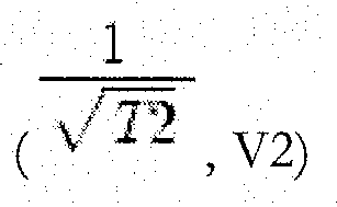

- The
OCV estimator 210 usesEquation 1 and coordinates that correspond to the first and second times T1 and T2 to detect a value of a slope (a) in the linear graph shown in FIG. 3B, as shown below.
- In addition, the
OCV estimator 210 generates a linear equation (or a line equation) given asEquation 2 in the graph having the slope (a), and as shown in FIG. 3B, and as discussed below.
- Here, X denotes a parameter in

- In the
OCV estimator 210, when the time t goes to infinity as shown in FIG. 3B, a voltage value that corresponds to the Y-axis coordinate value becomes the open circuit voltage (OCV). In this case, a value of the Y-axis coordinate is estimated (or extrapolated) as the OCV when an X-axis coordinate value is 0 (because
data storage unit 220 stores the battery state information. That is, thedata storage unit 220 includes a data table of the SOC that corresponds to the OCV. TheSOC establishment unit 230 receives the OCV from theOCV estimator 210, uses the data table of the SOC that corresponds to the OCV, and establishes the SOC that corresponds to the OCV. - FIG. 4 shows a flowchart representing a method of operating the battery management system according an aspect of the present invention.
- Initially, the
MCU 20 of theBMS 1 determines whether the battery is charged or discharged in operation S100. When it is determined in operation S100 that the battery is charged or discharged, the operation S100 is performed again. When it is determined in operation S100 that the battery is not charged or discharged, the first time T1 and the first battery voltage V1 that corresponds to the first time T1 are detected, and the second time T2 and the second battery voltage V2 that corresponds to the second time T2 are detected in operation S200. - A graph (or line) that passes through coordinates

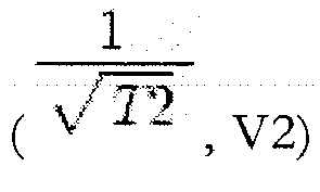
Equation 2 having the respective coordinates, in operation S300. - From the linear equation generated in operation S300, a value A (the Y-intercept) of the Y-axis coordinate when an X-axis coordinate value is 0 is estimated (or determined) as an OCV in operation S400. The OCV estimated in operation S400 is received, and an SOC that corresponds to the OCV is established in operation S500 by using a data table of the SOC that corresponds to the OCV.
- As described, shown is the battery management system and the method for establishing the SOC by estimating the OCV. According to aspects of the present invention, the first time T1 and the corresponding first battery voltage V1 are detected, the second time T2 and the corresponding second battery voltage V2 are detected, and a corresponding linear equation is generated. The OCV is then estimated using the generated linear equation. The SOC is established by using a data table of the SOC that corresponds to the OCV.
- According to aspects of the present invention, the OCV may be estimated quickly and within a short time. Accordingly, the battery management system to precisely estimate the SOC and the driving method thereof may be provided.
- In addition, since an SOC estimation error caused by an error in measuring the OCV is prevented, the battery management system for preventing the battery from being overcharged and over-discharged and the driving method thereof may be provided.
- While not required in all aspects, elements of the method can be implemented as software and/or firmware for use with one or more processors and/or computers. Moreover a processor and/or computer readable medium maybe encoded with computer and/or processor-executable instructions for performing the method.
- Additionally, although implemented as a battery management system of a vehicle, aspects of the present invention may be implemented with any rechargeable battery system.
- Additionally, although implemented as detecting a first and a second time data, aspects of the present invention may detect at least one voltage of the rechargeable battery that corresponds to the at least one time, to determine an open circuit voltage (OCV) of the rechargeable battery based on the at least one time and the at least one voltage, and to determine the SOC of the rechargeable battery that corresponds to the determined OCV.
- Although a few aspects of the present invention have been shown and described, it would be appreciated by those skilled in the art that changes may be made in the aspects without departing from the principles of the invention, the scope of which is defined in the claims.
Claims (12)
- A battery management system for establishing a state of charge (SOC) of a rechargeable battery, the battery management system comprising:means for measuring a battery voltage at a first time and a second time to determine corresponding first and second battery voltages;means for estimating an open circuit voltage (OCV) from the first and second voltages and the first and second times; andmeans for determining the SOC that corresponds to the OCV.
- The battery management system of claim 1, wherein the measuring means is arranged to measure the first voltage at a time when an effect of an internal resistance of the battery is negligible, and to measure the second voltage at a time after a predetermined period has passed from the first time to permit dissipation of polarization caused by electrolyte diffusion.
- The battery management system of claim 1 or 2, wherein the estimating means comprises:an OCV estimator for estimating the OCV by using the first and second voltages; and the SOC determining means comprises:an SOC establishment unit for receiving the OCV and determining the SOC that corresponds to the OCV.
- The battery management system of claim 3, wherein the OCV estimator is arranged to generate a linear equation given as


- A method of operating a battery management system for establishing a state of charge (SOC) of a rechargeable battery, the method comprising:measuring a battery voltage at a first time and a second time to determine corresponding first and second battery voltages;estimating an open circuit voltage (OCV) from the first and second voltages and the first and second times; anddetermining the SOC that corresponds to the OCV.
- A method according to claim 5, wherein the first and second time are determined based on when an effect of an internal resistance of the battery is eliminated, and after a predetermined period has passed to dissipate polarization caused by electrolyte diffusion.
- A method according to claim 5 or 6, wherein the OCV is a Y-intercept of a linear equation obtained from the determined first and second times and first and second voltages.
- A method according to claim 7, wherein the linear equation is


- A method according to any one of claims 5 to 8, further comprising:receiving the estimated OCV; andusing a table to determine the SOC that corresponds to the OCV.
- A method for obtaining a state of charge (SOC) of a rechargeable battery, the method comprising:detecting voltage of the rechargeable battery corresponding to time;determining an open circuit voltage (OCV) of the rechargeable battery using an inverse relationship of the time relative to the voltage; anddetermining the SOC of the rechargeable battery that corresponds to the determined OCV.
- A method according to claim 10, wherein the inverse relationship is the relationship that the voltage is inversely proportional to the square root of the time.
- A computer program which, when executed by a processor, is arranged to perform a method according to any one of claims 5 to 11.
Applications Claiming Priority (1)
| Application Number | Priority Date | Filing Date | Title |
|---|---|---|---|
| KR1020060086916A KR100805116B1 (en) | 2006-09-08 | 2006-09-08 | Battery management system and its driving method |
Publications (2)
| Publication Number | Publication Date |
|---|---|
| EP1901413A2 true EP1901413A2 (en) | 2008-03-19 |
| EP1901413A3 EP1901413A3 (en) | 2012-04-04 |
Family
ID=38855039
Family Applications (1)
| Application Number | Title | Priority Date | Filing Date |
|---|---|---|---|
| EP07115331A Withdrawn EP1901413A3 (en) | 2006-09-08 | 2007-08-30 | Battery management system and method |
Country Status (5)
| Country | Link |
|---|---|
| US (1) | US7684941B2 (en) |
| EP (1) | EP1901413A3 (en) |
| JP (1) | JP4472733B2 (en) |
| KR (1) | KR100805116B1 (en) |
| CN (1) | CN100585941C (en) |
Cited By (3)
| Publication number | Priority date | Publication date | Assignee | Title |
|---|---|---|---|---|
| FR2941053A1 (en) * | 2009-01-15 | 2010-07-16 | Peugeot Citroen Automobiles Sa | Device for estimating charge state of battery of motor vehicle e.g. car, has calculating unit estimating charge state of battery based on voltage correspondence table of deduced off-load voltage/ charge state |
| WO2013188415A3 (en) * | 2012-06-11 | 2014-02-06 | Panduit Corp. | Capacitor-based ups |
| EP2344900B1 (en) * | 2008-10-30 | 2018-07-18 | Commissariat à l'Energie Atomique | Method for determining the charging state of a battery in a charging or discharging phase |
Families Citing this family (28)
| Publication number | Priority date | Publication date | Assignee | Title |
|---|---|---|---|---|
| JP5163229B2 (en) * | 2008-03-28 | 2013-03-13 | 新神戸電機株式会社 | Battery state detection system and automobile equipped with the same |
| KR101187766B1 (en) * | 2008-08-08 | 2012-10-05 | 주식회사 엘지화학 | Apparatus and Method for cell balancing based on battery's voltage variation pattern |
| CN101488594B (en) * | 2009-02-16 | 2011-07-13 | 中兴通讯股份有限公司 | Management method for battery electric power |
| DE102009045526A1 (en) * | 2009-10-09 | 2011-04-14 | SB LiMotive Company Ltd., Suwon | Method for initialization and operation of a battery management system |
| EP2355229A1 (en) * | 2010-02-08 | 2011-08-10 | Fortu Intellectual Property AG | High voltage battery system and method for controlling same |
| CN102035000B (en) * | 2010-11-29 | 2012-07-25 | 新源动力股份有限公司 | A fuel cell stack output state estimation system and estimation method |
| US9407098B2 (en) | 2011-12-12 | 2016-08-02 | Apple Inc. | Determining a battery chemistry for a battery in a peripheral device |
| FR2987451A1 (en) * | 2012-02-29 | 2013-08-30 | St Microelectronics Grenoble 2 | DEVICE FOR MEASURING THE VACUUM VOLTAGE OF A BATTERY |
| JP5704108B2 (en) * | 2012-03-30 | 2015-04-22 | トヨタ自動車株式会社 | Battery system and estimation method |
| DE102012207806A1 (en) * | 2012-05-10 | 2013-11-14 | Robert Bosch Gmbh | Method for operating a battery system, battery system and motor vehicle |
| FR2990766B1 (en) * | 2012-05-15 | 2014-05-09 | Renault Sa | SYSTEM AND METHOD FOR ESTIMATING THE CHARGING STATE OF A BATTERY |
| CN104285156B (en) * | 2012-05-15 | 2016-12-21 | 丰田自动车株式会社 | The polar discrimination method of lithium-ion battery systems and lithium ion battery |
| JP6066163B2 (en) | 2012-05-17 | 2017-01-25 | 株式会社Gsユアサ | Open circuit voltage estimation device, state estimation device, and open circuit voltage estimation method |
| FR3006450B1 (en) * | 2013-06-04 | 2015-05-22 | Renault Sa | METHOD FOR ESTIMATING THE HEALTH STATUS OF AN ELECTROCHEMICAL CELL FOR STORING ELECTRIC ENERGY |
| KR102037378B1 (en) | 2013-07-04 | 2019-10-28 | 에스케이이노베이션 주식회사 | Method and apparatus for estimating SOC in constant current state, battery management system and energy storage system comprising the same |
| KR102079038B1 (en) * | 2013-09-30 | 2020-02-19 | 현대모비스 주식회사 | Intelligent Battery Sensor Apparatus and Method thereof |
| JP6260812B2 (en) * | 2013-12-05 | 2018-01-17 | パナソニックIpマネジメント株式会社 | Battery remaining capacity estimation device, battery remaining capacity determination method, and battery remaining capacity determination program |
| CN104714181B (en) * | 2013-12-11 | 2017-10-27 | 广州汽车集团股份有限公司 | It is a kind of to obtain voltage and the method and system of battery charge state relation |
| KR102527326B1 (en) | 2015-08-20 | 2023-04-27 | 삼성전자주식회사 | A method and a battery system for predicting State of Charge (SoC) of a battery |
| JP6365497B2 (en) * | 2015-10-14 | 2018-08-01 | 株式会社オートネットワーク技術研究所 | CURRENT CONTROL DEVICE, CURRENT CONTROL METHOD, AND COMPUTER PROGRAM |
| US10436845B2 (en) * | 2016-03-01 | 2019-10-08 | Faraday & Future Inc. | Electric vehicle battery monitoring system |
| JP6645584B2 (en) * | 2016-08-26 | 2020-02-14 | 株式会社豊田自動織機 | Power storage device |
| US10338147B2 (en) * | 2016-10-31 | 2019-07-02 | Semiconductor Components Industries, Llc | Methods and apparatus for determining a relative state of charge of a battery |
| JP7401444B2 (en) * | 2018-02-10 | 2023-12-19 | ヨウオン テクノロジー カンパニー、リミテッド | Electrically assisted bicycle, its power management system and management method |
| KR102844868B1 (en) | 2019-10-18 | 2025-08-08 | 주식회사 엘지에너지솔루션 | Apparatus and method for estimating state of charge |
| KR102851926B1 (en) * | 2020-08-13 | 2025-08-27 | 주식회사 엘지에너지솔루션 | Apparatus and method for managing battery |
| KR102638180B1 (en) * | 2021-11-03 | 2024-02-16 | 엘지전자 주식회사 | Energy storage system and method for operating the same |
| WO2023162274A1 (en) * | 2022-02-28 | 2023-08-31 | 京セラ株式会社 | Soc estimation device, program, and soc estimation method |
Citations (1)
| Publication number | Priority date | Publication date | Assignee | Title |
|---|---|---|---|---|
| US20020145430A1 (en) | 2001-02-23 | 2002-10-10 | Youichi Arai | Method and apparatus for estimating terminal voltage of battery, method and apparatus for computing open circuit voltage of battery, and method and apparatus for computing battery capacity |
Family Cites Families (6)
| Publication number | Priority date | Publication date | Assignee | Title |
|---|---|---|---|---|
| US6639385B2 (en) | 2001-08-07 | 2003-10-28 | General Motors Corporation | State of charge method and apparatus |
| JP3770137B2 (en) | 2001-10-17 | 2006-04-26 | トヨタ自動車株式会社 | Secondary battery control device for vehicle |
| JP2004354050A (en) * | 2002-05-14 | 2004-12-16 | Yazaki Corp | Battery state of charge estimation method, open circuit voltage estimation method, and deterioration degree calculation method and apparatus |
| US6791464B2 (en) | 2002-10-28 | 2004-09-14 | Bppower Inc. | Apparatus of monitoring motor vehicle's electric power and method thereof |
| JP3714321B2 (en) | 2002-11-25 | 2005-11-09 | 日産自動車株式会社 | Secondary battery charge rate estimation device |
| EP2270526A1 (en) * | 2003-07-09 | 2011-01-05 | Premium Power Corporation | Device for monitoring and charging of a selected group of battery cells |
-
2006
- 2006-09-08 KR KR1020060086916A patent/KR100805116B1/en not_active Expired - Fee Related
-
2007
- 2007-07-03 JP JP2007175312A patent/JP4472733B2/en not_active Expired - Fee Related
- 2007-08-24 CN CN200710147713A patent/CN100585941C/en not_active Expired - Fee Related
- 2007-08-30 EP EP07115331A patent/EP1901413A3/en not_active Withdrawn
- 2007-09-06 US US11/850,701 patent/US7684941B2/en not_active Expired - Fee Related
Patent Citations (1)
| Publication number | Priority date | Publication date | Assignee | Title |
|---|---|---|---|---|
| US20020145430A1 (en) | 2001-02-23 | 2002-10-10 | Youichi Arai | Method and apparatus for estimating terminal voltage of battery, method and apparatus for computing open circuit voltage of battery, and method and apparatus for computing battery capacity |
Cited By (5)
| Publication number | Priority date | Publication date | Assignee | Title |
|---|---|---|---|---|
| EP2344900B1 (en) * | 2008-10-30 | 2018-07-18 | Commissariat à l'Energie Atomique | Method for determining the charging state of a battery in a charging or discharging phase |
| FR2941053A1 (en) * | 2009-01-15 | 2010-07-16 | Peugeot Citroen Automobiles Sa | Device for estimating charge state of battery of motor vehicle e.g. car, has calculating unit estimating charge state of battery based on voltage correspondence table of deduced off-load voltage/ charge state |
| WO2013188415A3 (en) * | 2012-06-11 | 2014-02-06 | Panduit Corp. | Capacitor-based ups |
| US9966758B2 (en) | 2012-06-11 | 2018-05-08 | Panduit Corp. | Capacitor-based UPS |
| US10516263B2 (en) | 2012-06-11 | 2019-12-24 | Panduit Corp. | Capacitor-based UPS |
Also Published As
| Publication number | Publication date |
|---|---|
| KR100805116B1 (en) | 2008-02-21 |
| EP1901413A3 (en) | 2012-04-04 |
| CN101141016A (en) | 2008-03-12 |
| JP4472733B2 (en) | 2010-06-02 |
| US20080065336A1 (en) | 2008-03-13 |
| US7684941B2 (en) | 2010-03-23 |
| JP2008064740A (en) | 2008-03-21 |
| CN100585941C (en) | 2010-01-27 |
Similar Documents
| Publication | Publication Date | Title |
|---|---|---|
| US7684941B2 (en) | Battery management system and driving method thereof | |
| EP1914559B1 (en) | Battery management system (BMS) and driving method thereof | |
| US7800345B2 (en) | Battery management system and method of operating same | |
| EP1801604B1 (en) | Method for compensating state of charge of battery and battery management system using the same | |
| EP1801947B1 (en) | Method for compensating state of charge of battery and battery management system using the same | |
| US7684942B2 (en) | Battery management system and driving method thereof | |
| US7768235B2 (en) | Battery management system and method for automotive vehicle | |
| JP4949086B2 (en) | Battery management system and operating method thereof | |
| EP1801606B1 (en) | Method for compensating state of charge of battery, battery management system using the method, and hybrid vehicle having the battery management system | |
| EP1897772B1 (en) | Battery management system and driving method thereof | |
| US7652449B2 (en) | Battery management system and driving method thereof | |
| EP1777794B1 (en) | Battery management system and method of determining a state of charge of a battery | |
| KR20080033628A (en) | Battery Management System and Its Driving Method | |
| KR101117636B1 (en) | Method of estimating SOC for battery and battery management system using the same | |
| KR20070040065A (en) | SOC estimation method of battery and battery management system using same |
Legal Events
| Date | Code | Title | Description |
|---|---|---|---|
| PUAI | Public reference made under article 153(3) epc to a published international application that has entered the european phase |
Free format text: ORIGINAL CODE: 0009012 |
|
| 17P | Request for examination filed |
Effective date: 20070830 |
|
| AK | Designated contracting states |
Kind code of ref document: A2 Designated state(s): AT BE BG CH CY CZ DE DK EE ES FI FR GB GR HU IE IS IT LI LT LU LV MC MT NL PL PT RO SE SI SK TR |
|
| AX | Request for extension of the european patent |
Extension state: AL BA HR MK YU |
|
| RAP1 | Party data changed (applicant data changed or rights of an application transferred) |
Owner name: SAMSUNG SDI CO., LTD. |
|
| PUAL | Search report despatched |
Free format text: ORIGINAL CODE: 0009013 |
|
| AK | Designated contracting states |
Kind code of ref document: A3 Designated state(s): AT BE BG CH CY CZ DE DK EE ES FI FR GB GR HU IE IS IT LI LT LU LV MC MT NL PL PT RO SE SI SK TR |
|
| AX | Request for extension of the european patent |
Extension state: AL BA HR MK RS |
|
| RIC1 | Information provided on ipc code assigned before grant |
Ipc: G01R 31/36 20060101ALI20120229BHEP Ipc: H02J 7/00 20060101AFI20120229BHEP |
|
| RAP1 | Party data changed (applicant data changed or rights of an application transferred) |
Owner name: SAMSUNG SDI CO., LTD. |
|
| AKX | Designation fees paid |
Designated state(s): DE FR GB HU |
|
| STAA | Information on the status of an ep patent application or granted ep patent |
Free format text: STATUS: THE APPLICATION HAS BEEN WITHDRAWN |
|
| 18W | Application withdrawn |
Effective date: 20160616 |