EP1901400A2 - A wire cover and a locking construction therefor - Google Patents
A wire cover and a locking construction therefor Download PDFInfo
- Publication number
- EP1901400A2 EP1901400A2 EP07017910A EP07017910A EP1901400A2 EP 1901400 A2 EP1901400 A2 EP 1901400A2 EP 07017910 A EP07017910 A EP 07017910A EP 07017910 A EP07017910 A EP 07017910A EP 1901400 A2 EP1901400 A2 EP 1901400A2
- Authority
- EP
- European Patent Office
- Prior art keywords
- engaging
- resilient
- connector
- wire
- partly
- Prior art date
- Legal status (The legal status is an assumption and is not a legal conclusion. Google has not performed a legal analysis and makes no representation as to the accuracy of the status listed.)
- Granted
Links
- 238000010276 construction Methods 0.000 title claims description 8
- 230000013011 mating Effects 0.000 claims abstract description 61
- 238000005452 bending Methods 0.000 claims description 3
- 238000006073 displacement reaction Methods 0.000 description 5
- 230000000694 effects Effects 0.000 description 2
- 230000004048 modification Effects 0.000 description 2
- 238000012986 modification Methods 0.000 description 2
- 230000008719 thickening Effects 0.000 description 2
- 239000011230 binding agent Substances 0.000 description 1
- 230000001419 dependent effect Effects 0.000 description 1
- 230000002542 deteriorative effect Effects 0.000 description 1
- 238000007689 inspection Methods 0.000 description 1
- 238000000034 method Methods 0.000 description 1
- 230000000149 penetrating effect Effects 0.000 description 1
- 230000009467 reduction Effects 0.000 description 1
- 230000008439 repair process Effects 0.000 description 1
Images


Classifications
-
- H—ELECTRICITY
- H01—ELECTRIC ELEMENTS
- H01R—ELECTRICALLY-CONDUCTIVE CONNECTIONS; STRUCTURAL ASSOCIATIONS OF A PLURALITY OF MUTUALLY-INSULATED ELECTRICAL CONNECTING ELEMENTS; COUPLING DEVICES; CURRENT COLLECTORS
- H01R13/00—Details of coupling devices of the kinds covered by groups H01R12/70 or H01R24/00 - H01R33/00
- H01R13/46—Bases; Cases
- H01R13/502—Bases; Cases composed of different pieces
- H01R13/506—Bases; Cases composed of different pieces assembled by snap action of the parts
-
- H—ELECTRICITY
- H01—ELECTRIC ELEMENTS
- H01R—ELECTRICALLY-CONDUCTIVE CONNECTIONS; STRUCTURAL ASSOCIATIONS OF A PLURALITY OF MUTUALLY-INSULATED ELECTRICAL CONNECTING ELEMENTS; COUPLING DEVICES; CURRENT COLLECTORS
- H01R13/00—Details of coupling devices of the kinds covered by groups H01R12/70 or H01R24/00 - H01R33/00
- H01R13/58—Means for relieving strain on wire connection, e.g. cord grip, for avoiding loosening of connections between wires and terminals within a coupling device terminating a cable
- H01R13/5804—Means for relieving strain on wire connection, e.g. cord grip, for avoiding loosening of connections between wires and terminals within a coupling device terminating a cable comprising a separate cable clamping part
- H01R13/5812—Means for relieving strain on wire connection, e.g. cord grip, for avoiding loosening of connections between wires and terminals within a coupling device terminating a cable comprising a separate cable clamping part the cable clamping being achieved by mounting the separate part on the housing of the coupling device
Definitions
- the present invention relates to a wire cover, for example, to be mounted on wires connected with a connector, and to a locking construction therefor.
- a wire cover disclosed Japanese Unexamined Patent Publication No. 2004-348988 is known, for example, as a wire cover of this type.
- This wire cover is provided with a wire pressing portion to be brought into contact with bent parts of wires drawn out from a connector, and this wire pressing portion is fixed to a connector housing by a resilient engaging piece.
- a connector is arranged in a small space where other parts are densely arranged around.
- a connector housing cannot be provided with a locking structure for the wire cover since being maximally miniaturized.
- the wire cover is forced to be fixed to a mating member, to which the connector is attached, instead of being attached to the connector.
- a wire cover is fixed to a mating member in the door, to which this connector is attached, instead of being fixed to the connector as described above.
- the present invention was developed in view of the above problems, and an object thereof is to enable a wire pressing portion to be easily detached from a mating member by at least partly inserting a disengagement jig from the base end side of a resilient engaging piece of the wire pressing portion.
- a wire pressing portion to be easily detached from a mating member by at least partly inserting a disengagement jig from the base end side of a resilient engaging piece of the wire pressing portion.
- a wire cover for bending at least one wire or cable drawn out from a connector in a direction different from a draw-out direction comprising a connector-side fixing portion to be fixed to the connector, a wire pressing portion to be held substantially in contact with the wire, and a connecting portion connecting the connector-side fixing portion and wire pressing portion, wherein the wire pressing portion includes at least one resilient engaging piece projecting therefrom and formed with at least one engaging portion and can be fixed to a mating member at least partly fitted with or to the connector by engaging the at least one engaging portion with at least one engageable portion provided at the mating member, and at least one catching portion for disengagement, with which a jig at least partly inserted (particularly from the base end side of the resilient engaging piece) is brought into catching engagement to make the resilient engaging piece displaceable in such a direction as to disengage the engaging portion and engageable portion.
- the jig is to be at least partly inserted from the base end side of the resilient engaging piece to be brought into catching engagement with the at least one catching portion.
- the jig can be inserted from the base end side of the resilient engaging piece to bring the leading end thereof into catching engagement with the catching portion.
- the resilient engaging piece can be displaced in a disengaging direction to disengage the engaging portion and engageable portion. Therefore, the resilient engaging piece can be detached from the mating member by inserting the jig from the base end side of the resilient engaging piece.
- the mating member includes a pair of engaging wall portions each having the engageable portion and substantially facing each other, and a pair of resilient engaging pieces are so provided as to be fittable to the corresponding engaging wall portions from outer sides.
- each resilient engaging piece is integrally or unitarily formed with an auxiliary wall at least partly insertable at an inner side of the corresponding engaging wall portion to sandwich the engaging wall portion between the resilient engaging piece and the auxiliary wall.
- the engaging wall portions can be sandwiched between the resilient engaging pieces and auxiliary walls.
- the engaging portions and engageable portions can be held engaged. Even if the resilient engaging pieces should try to be resiliently deformed outward, there is no likelihood that the engaging portions and engageable portions are easily disengaged since the resilient engaging pieces become more difficult to resiliently deform than in the case where the resilient engaging pieces are provided separately from the auxiliary walls.
- the engaging portions of the resilient engaging pieces are substantially in the form of engaging holes and the engageable portions of the engaging wall portions are in the form of engaging projections.
- engaging forces of the engaging projections and engaging holes are determined by the depth of the engaging holes, i.e. the thickness of the engaging wall portions.
- the depth of the engaging holes i.e. the thickness of the engaging wall portions.
- the resilient engaging pieces are thinned, this brings about a reduction in resilient forces, thereby losing the significance of integrally providing the resilient engaging pieces with the auxiliary walls.
- the depth of the engaging holes can be increased by thickening the resilient engaging pieces at sides opposite to the engaging wall portions. Therefore, the engaging forces can be enhanced without reducing the resilient forces of the resilient engaging pieces.
- a locking construction for a wire cover in particular according to the above invention or a preferred embodiment tehreof, including a wire pressing portion to be brought into contact with at least one bent part of at least one wire or cable drawn out from a connector, comprising:
- the disengagement jig preferably can be inserted from the base end side of the resilient engaging piece to insert the leading end thereof into a clearance between the engaging portion and mating member through the disengagement recess.
- the engaging portion can be disengaged by being displaced in a direction away from the mating member. Therefore, the resilient engaging piece can be detached from the mating member by inserting the disengagement jig from the base end side of the resilient engaging piece.
- a pair of resilient engaging pieces project to hold the engaging projection at least partly therebetween.
- each engaging portion is substantially bent or U-shaped as a whole by integrally or unitarily connecting at least the leading ends of the both resilient engaging pieces.
- the disengagement recesses can be located at positions seeable from the base end sides of the resilient engaging pieces with the resilient engaging pieces attached to the mating member. Further, the disengagement jig can be inserted in such a posture substantially parallel to a projecting direction of the resilient engaging pieces. Therefore, a disengaging operation can be more easily performed than in the case where through holes are formed at the leading end sides of the resilient engaging pieces and leading end parts of surrounding walls forming the through holes serve as engaging portions.
- the mating member includes a pair of engaging wall portions each having the engaging projection and substantially facing each other, and a pair of resilient engaging pieces are so provided as to be at least partly fittable to the corresponding engaging wall portions from outer sides.
- each resilient engaging piece is integrally or unitarily formed with at least one auxiliary wall at least partly insertable at an inner side of the corresponding engaging wall portion to sandwich or arrange the engaging wall portion between the resilient engaging piece and the auxiliary wall.
- the engaging wall portions can be sandwiched between the resilient engaging pieces and auxiliary walls.
- the engaging portions and engaging projections can be held engaged. Even if the resilient engaging pieces should try to be resiliently deformed outward, there is no likelihood that the engaging portions and engaging projections are easily disengaged since the resilient engaging pieces become more difficult to resiliently deform than in the case where the resilient engaging pieces are provided separately from the auxiliary walls.
- a wire cover 1 of a preferred embodiment of the present invention is for bending one or more wires W (actually, a wire group formed by bundling a plurality of wires W, but merely called wires W in the following description) drawn out through a wire draw-out surface of a connector (not shown) attached to a mating member 40 in a direction different from a draw-out direction and guiding the wires W in a specified (predetermined or predeterminable) direction.
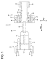
- FIG. 1 is a bottom view of the wire cover 1, and the unillustrated wires W are arranged at the bottom side of the wire cover 1.
- the wire cover 1 is provided with a connector-side fixing portion 10 to be fixed to the connector, a wire pressing portion 20 to be fixed to the mating member 40 and a connecting portion 30 integrally or unitarily connecting the connector-side fixing portion 10 and wire pressing portion 20.
- the mating member 40 is provided with one or more, preferably a pair of engaging wall portions 41 preferably substantially opposed to each other, and one or more, preferably a pair of engaging projections (corresponding to preferred engageable portions) 42 projecting from one or more surfaces of end portions of the (preferably both) engaging wall portion(s) 41 preferably substantially opposite to the facing surfaces as shown in FIG. 6.
- FIG. 6 reference is made to a direction normal to the plane of FIG.
- FIG. 1 concerning vertical direction VD with a back side set as an upper side, reference is made to transverse direction in FIG. 1 concerning forward and backward directions FBD with a shown right side set as a front side, and reference is made to vertical direction in FIG. 1 concerning width direction WD.
- the connector-side fixing portion 10 includes one or more, preferably a pair of side plates 11 preferably substantially facing each other in width direction WD, and the upper ends of the side plates 11 are connected by an upper end wall 12.
- One or more fixing plates 13 projecting substantially backward or along the forward and backward directions FBD are integrally or unitarily formed on the outer side surfaces of the (respective) side plate(s) 11, and one or more fixing grooves 14 extending substantially upward from the bottom end are formed in the fixing plate(s) 13.
- the fixing grooves 14 can fix the connector-side fixing portion 10 to the connector by being engaged with one or more lock projections (not shown) provided on the connector.
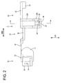
- the connecting portion 30 includes a flexible resilient portion 31 extending substantially forward from (preferably the front end edge of) the upper end wall 12, and a wire constraining portion 32 coupled to (preferably the front end edge of) the resilient portion 31.
- the width of the resilient portion 31 preferably is set slightly shorter than a distance between the both side plates 11 of the connector-side fixing portion 10. Upon being bent toward the mating member 40, the resilient portion 31 comes to be arranged between the both side plates 11 and a bend accommodating portion is formed by the inner side surfaces of the both side plates 11 and the inner surface of the resilient portion 31.
- the wire constraining portion 32 preferably substantially is rod- or column-shaped and formed substantially not to be resiliently deformable or to have a significantly reduced resiliency as compared to the resilient portion 31.
- This wire constraining portion 32 is to be tied with or fixed to the wires W by a binding band, clamp or the like (not shown).
- the wire pressing portion 20 includes a (preferably substantially rectangular) base plate portion 21 having a rear portion (preferably the rear end edge) coupled to the wire constraining portion 32, and (preferably four) side walls projecting downward at the front and/or rear sides of the substantially opposite side edges of the base plate portion 21.
- the (preferably two) side wall(s) at the front side serve as one or more, preferably a pair of guiding projections 22 and the one or those at the rear side serve(s) as one or more, preferably a pair of resilient engaging pieces 23.
- the (preferably both) guiding projection(s) 22 project(s) downward from the (preferably substantially opposite) sides of (preferably the front end of) the base plate portion 21 preferably while substantially facing each other.
- a projecting height of the guiding projections 22 preferably is set substantially equal to or slightly larger than the diameter of the wires W. Since the lower surface of the base plate portion 21 is to come substantially in contact with the wires W due to resilient forces of the wires W when the wires W are bent, the wires W can be reliably guided to extend substantially forward or along the forward and backward directions FBD from (preferably the front end of) the base plate portion 21 by arranging the wires W at least partly adjacent to or between the both guiding projections 22.
- the (preferably both) resilient engaging pieces 23 include one or more deformation restricted portions 23A extending downward from the (preferably substantially opposite) side(s) of (preferably the rear end of) the base plate portion 21 preferably while substantially facing each other, and one or more deformation permitted portions 23B projecting downward from the outer side surfaces of (preferably the bottom ends of) the deformation restricted portions 23A while being supported only one side.
- Each deformation permitted portion 23B is comprised of one or more, preferably a pair of supporting arms 23B1 projecting in such a manner as to hold the engaging projection 42 close thereto or at least partly therebetween, and preferably a bridging portion 23B2 bridging the leading ends of the both supporting arms 23B1 to integrally or unitarily connect them, and is substantially U-shaped as a whole.
- the upper surface of the bridging portion 23B2 is set at a position lower than the bottom surfaces of the deformation restricted portions 23A, whereby an engaging hole (corresponding to a preferred engaging portion) 25 is formed by the substantially opposite inner surfaces of the both supporting arms 23B1, the upper surface of the bridging portion 23B2 and the lower surface of the deformation restricted portion 23A.
- the engaging hole 25 enables the wire pressing portion 20 to be fixed to the mating member 40 by being engaged with the engaging projection 42.
- the lower surface of the base plate portion 21 receives upward acting resilient repulsive forces from the bent wires W and the lower surfaces of the engaging projections 42 and the upper surfaces of the bridging portions 23B2 are held substantially in contact with each other.
- clearances S are formed between the lower surfaces of the deformation restricted portions 23A and the upper surfaces of the engaging wall portions 41.
- the clearances S (FIG. 6) are provided because the upper surfaces of the bridging portions 23B2 make pivotal displacements about the base ends thereof and the bridging portions 23B2 pass positions above those before the displacements upon moving over the engaging projections 42. Accordingly, the clearances S are set to have such a length as to enable the bridging portions 23B2 to move over the engaging projections 42 with the lower surfaces of the deformation restricted portions 23A and the upper surfaces of the engaging wall portions 41 held in contact.
- auxiliary walls 24 projecting substantially downward from the base plate portion 21 preferably while substantially facing each other are formed on the inner side(s) of the (preferably both) resilient engaging piece(s) 23.
- Each auxiliary wall 24 is comprised of a facing wall 24 arranged to substantially face the resilient engaging piece 23 and restricting walls 24B for restricting a resilient deformation of the facing wall 24A by extending outward substantially in width direction WD from the front and rear edges of the facing wall 24A, and is in the form of a column having a U-shaped cross section as a whole.
- the bottom ends of the auxiliary walls 24 are set at such height positions preferably substantially aligned with the bottom ends of the deformation permitted portions 23B.
- the outer widthwise edges of the restricting walls 24B are integrally or unitarily connected with the deformation restricted portions 23A, whereby the restricting walls 24B can restrict resilient deformations of the deformation restricted portions 23A while permitting only resilient deformations of the deformation permitted portions 23B substantially in width direction WD. Further, resilient forces of the deformation permitted portions 23B become larger than in the case where the deformation restricted portions 23A and the auxiliary walls 24 are separately formed, wherefore the engaging holes 25 and engaging projections 42 can be engaged with enhanced forces. It should be noted that a distance between the inner surfaces of the deformation permitted portions 23B and the lateral ends of the restricting walls 24B preferably is set substantially equal to or slightly larger than the thickness of the engaging wall portions 41.
- a bulging portion 27 projecting outward substantially in width direction WD is formed on the outer side surface of the bridging portion 23B2 of each deformation permitted portion 23B.
- This bulging portion 27 is formed with a catching hole (corresponding to a preferred catching portion) 26 penetrating substantially in vertical direction (projecting direction of the deformation permitted portion 23B).
- the catching hole 26 is located at a position which can be seen from the base end side of the resilient engaging piece 23 and dimensioned such that a minus driver 50 (corresponding to a preferred jig) is at least partly insertable thereinto from the base end side of the resilient engaging piece 23.
- the deformation permitted portion 23B can be displaced outward substantially in width direction WD (direction to disengage the engaging hole 25 and engaging projection 42) by at least partly inserting the substantially flat or minus driver 50 from the base end side of the resilient engaging piece 23 and bringing it into catching engagement with the catching hole 26.
- the catching hole 26 is located at the position which can be seen from the base end side of the resilient engaging piece 23 because it is difficult to at least partly insert the leading end of the minus driver 50 into the catching hole 26 even if the minus driver 50 is at least partly inserted from the base end side of the resilient engaging piece 23 in the case where the catching hole 26 should be located at a position unseeable from the base end side of the resilient engaging piece 23.
- the attachment of the wire pressing portion 20 to the mating member 40 is described.
- the resilient portion 31 is resiliently deformed and the wires W are at least partly bent, whereby the wires W come substantially into contact with the lower surface of the base plate portion 21 by resilient repulsive forces of the wires W.
- the engaging wall portions 41 at least partly enter between the deformation permitted portions 23B and the auxiliary walls 24, and the leading ends of the deformation permitted portions 23B move onto the engaging projections 42 to resiliently deform the deformation permitted portions 23B outward in width direction WD.
- the deformation permitted portions 23B When the leading ends of the deformation permitted portions 23B move over the engaging projections 42, the deformation permitted portions 23B are resiliently at least partly restored to engage the engaging holes 25 and engaging projections 42. In this way, the wire pressing portion 20 is fixed to the mating member 40.
- the leading end of the minus driver 50 is at least partly inserted into one catching hole 25 from the base end side of the resilient engaging piece 23. Then, the leading end of the minus driver 50 is displaced in such a disengaging direction (preferably outward substantially in width direction WD) to disengage the engaging hole 25 and engaging projection 42. Subsequently, the leading end of the minus driver 50 is or can be at least partly inserted into the other catching hole 25 from the base end side of the resilient engaging piece 23 and displaced in the disengaging direction (outward in width direction WD) to disengage the engaging hole 25 and engaging projection 42, whereby the wire pressing portion 20 can be detached from the mating member 40.
- a disengaging direction preferably outward substantially in width direction WD
- this embodiment has the following effects.
- a wire cover 1 is provided with a connector-side fixing portion 10 to be fixed to a connector, a wire pressing portion 20 to be held substantially in contact with one or more wires or cables W, and a connecting portion 30 connecting the connector-side fixing portion 10 and wire pressing portion 20.
- One or more resilient engaging pieces 23 formed with one or more respective engaging holes 25 project from the wire pressing portion 20, and the wire pressing portion 20 can be fixed to a mating member 40 at least partly fitted with the connector by engaging the one or more engaging holes 25 with one or more respective engaging projections 42 provided at the mating member 40.
- At or near the leading ends of the resilient engaging pieces 23 are formed one or more catching holes 26 used for disengagement, with each of which a jig 50 at least partly inserted from the base end side of the resilient engaging piece 23 can be brought into catching engagement to displace the resilient engaging piece 23 in such a direction as to disengage the engaging hole 25 and engaging projection 42.
- a wire cover 1 of a further preferred embodiment of the present invention is provided with a wire pressing portion 20 to be held in contact with one or more bent parts of one or more wires or cables W (actually, a wire group formed by bundling a plurality of wires W, but merely called wires W in the following description) drawn out from a connector (not shown), and the wire pressing portion 20 is to be fixed to a mating member 40 to which the connector is attached. As shown in FIG.
- the mating member 40 is provided with one or more, preferably a pair of engaging wall portions 41 facing each other, and one or more, preferably a pair of engaging projections 42 projecting from one or more surfaces of end portions of the both engaging wall portions 41 preferably substantially opposite to the facing surfaces of the (preferably both) engaging wall portions 41.
- Each engaging projection 42 is comprised of one or more, preferably a pair of projections spaced apart by a specified (predetermined or predeterminable) distance.
- the wire pressing portion 20 includes a bend accommodating portion 20A for at least partly accommodating the bent parts of the wires W, a wire constraining portion 20B to be tied with or fixed to the wires W by a binding band, binder, clip or the like (not shown), and a lock portion 20C coupled to the bend accommodating portion 20A via the wire constraining portion 20B and to be fixed to the mating member 40.
- the lock portion 20C is comprised of a (preferably substantially rectangular) base plate portion 21 connected with the wire constraining portion 20B and a pair of side plates 22 projecting substantially downward from the opposite side edges of the base plate portion 21, and preferably substantially has a U-shaped cross section as a whole.
- On the outer side surfaces of the both side plates 22, one or more, preferably a pair of resilient engaging pieces 23 are formed to project substantially downward from (preferably the bottom ends of) the (preferably both) side plates 22 preferably while substantially facing each other and being supported only at one side.
- Each resilient engaging piece 23 is comprised of one or more, preferably a pair of supporting arms 23A projecting to hold the engaging projection close thereto or at least partly therebetween and an engaging portion 23B projecting from, preferably bridging the leading ends of the both supporting arms 23A preferably to integrally or unitarily couple them, and has a bent or substantially U-shaped cross section as a whole.
- the engaging portion 23B is located at a position which can be seen from the base end side of the resilient engaging piece 23, and a disengagement jig (such as a minus or flat driver 50 to be described later) can be at least partly inserted preferably in such a posture substantially parallel to a projecting direction of the resilient engaging piece 23.
- the distal or upper surface of the engaging portion 23B is set at a position lower than the bottom surfaces of the side plates 22, whereby an engaging hole 25 is formed by the opposite inner surfaces of the both supporting arms 23A, the upper surface of the engaging portion 23B and the lower surface of the side plate 22.
- the engaging hole 25 is engageable with the engaging projection 42 and can fix the wire pressing portion 20 to the mating member 40 by the engagement of the upper surface of the engaging portion 23B and the lower surface of the engaging projection 42.
- the engaging portion 23B preferably is formed thinner than the supporting arms 23B by having the inner side thereof thinned. Accordingly, the inner surface of the engaging portion 23B is at a specified (predetermined or predeterminable) distance from the outer surface of the engaging wall portion 41.
- the lower surface of the base plate portion 21 receives upward acting resilient repulsive forces from the bent wires W and the lower surfaces of the engaging projections 42 and the upper surfaces of the engaging portions 23B are urged towards each other and/or held substantially in contact with each other.
- clearances S are formed between the lower surfaces of the side plates 22 and the upper surfaces of the engaging wall portions 41.
- the clearances S are provided because the upper surfaces of the engaging portions 23B make pivotal displacements about the base ends thereof and the engaging portions 23B pass positions above those before the displacements upon moving over the engaging projections 42. Accordingly, the clearances S are set to have such a length as to enable the engaging portions 23B to move over the engaging projections 42 with the lower surfaces of the side plates 22 and the upper surfaces of the engaging wall portions 41 held in contact.
- Each auxiliary wall 24 preferably is comprised of a facing wall 24A arranged to face the side plate 22 and one or more restricting walls 24B for restricting a resilient deformation of the facing wall 24A by extending substantially outward in width direction WD from the front and/or rear portions or edges of the facing wall 24A, and preferably is in the form of a column having a U-shaped cross section as a whole.
- the bottom ends of the auxiliary walls 24 preferably are set at such height positions substantially aligned with the bottom ends of the resilient engaging pieces 23.
- the outer widthwise edges of the restricting walls 24B are integrally or unitarily connected with the side plate 22, whereby the restricting walls 24B can restrict resilient deformations of the side plates 22 while permitting only resilient deformations of the resilient engaging pieces 23 in width direction WD.
- engaging forces of the engaging holes 25 and engaging projections 42 can be more enhanced as compared to the case where the side plates 22 are formed separately from the auxiliary walls 24.
- a distance between the inner surfaces of the supporting arms 23A and the lateral ends of the restricting walls 24B preferably is set substantially equal to or slightly larger than the thickness of the engaging wall portions 41.
- each engaging projection 42 preferably is comprised of a front projection 42A and a rear projection 42B at a specified (predetermined or predeterminable) distance from each other.
- a disengagement recess 43 is defined between the both projections 42A, 42B, and the engaging portion 23B is located at the position which can be seen from the base end side of the resilient engaging piece 23 through this disengagement recess 43.
- the spacing between the both projections 42A, 42B is set such that the leading end of the minus driver 50 (corresponding to a preferred jig or disengagement jig) is at least partly insertable.
- the spacing between the inner surface of the engaging portion 23B and the outer surface of the engaging wall portion 41 is set such that the leading end of the minus driver 50 is at least partly insertable.
- the resilient engaging piece 23 can be resiliently displaced in such a direction (preferably substantially outward in width direction WD) to disengage the engaging hole 25 and engaging projection 42 by at least partly inserting the minus driver 50 from the base end side of the resilient engaging piece 23 and at least partly inserting the leading end of the minus driver 50 into the clearance between the inner surface of the engaging portion 23B and the outer surface of the engaging wall portion 41 through the disengagement recess 43.
- the minus driver 50 cannot be inserted into the disengagement recess 43.
- the disengagement recess 43 is located at the position which can be seen from the base end side of the resilient engaging piece 23.
- the attachment of the wire pressing portion 20 to the mating member 40 is described.
- the wire pressing portion 20 is pushed substantially toward the engaging projections 42, the wires W are bent, the bent parts of the wires W are at least partly accommodated into the bend accommodating portion 20A, and the wires W at least partly come substantially into contact with the lower surface of the base plate portion 21 by resilient repulsive forces of the wires W.
- the engaging wall portions 41 at least partly enter between the resilient engaging pieces 23 and auxiliary walls 24, and the engaging portions 23B move onto or over the engaging projections 42 to resiliently deform the resilient engaging pieces 23 in a deforming direction (preferably substantially outward in width direction WD).
- the resilient engaging pieces 23 are resiliently at least partly restored to engage the engaging portions 23B and engaging projections 42. In this way, the wire pressing portion 20 is fixed to the mating member 40.
- the leading end of the minus driver 50 is at least partly inserted through the disengagement recess 43 from the base end side of one resilient engaging piece 23 to at least partly enter the clearance between the engaging portion 23B and engaging wall portion 41. Then, the leading end of the minus driver 50 is displaced in a displacement direction (preferably substantially outward in width direction WD) to disengage the engaging portion 23B and engaging projection 42.
- the leading end of the minus driver 50 is or can be at least partly inserted through the disengagement recess 43 from the base end side of the other resilient engaging piece 23 to at least partly enter the clearance between the engaging portion 23B and engaging wall portion 41, thereby displacing the resilient engaging piece 23 (preferably substantially outward in width direction WD) to disengage the engaging portion 23B and engaging projection 42.
- the wire pressing portion 20 can be detached from the mating member 40.
- this embodiment has the following effects.
- a wire cover 1 is provided with a wire pressing portion 20 to be brought into contact with one or more bent parts of one or more wires W drawn out from a connector.
- a mating member 40 to or with which the connector is attached or connected includes one or more, preferably a pair of engaging wall portions 41 having one or more engaging projections 42 and preferably substantially facing each other.
- One or more resilient engaging pieces 23 project from the wire pressing portion 20 substantially toward the engaging projection(s) 42.
- Each resilient engaging piece 23 includes an engaging portion 23B for fixing the resilient engaging piece 23 to the mating member 40 by being engaged with the corresponding engaging projection 42.
- Each engaging projection 42 is formed with at least one disengagement recess 43 for at least partly receiving the leading end of a minus driver 50 at least partly inserted from the base end side of the resilient engaging piece 23 so that the engaging portion 23B can be displaced by the minus driver 50 to be disengaged from the engaging projection 42.
Landscapes
- Installation Of Indoor Wiring (AREA)
- Connector Housings Or Holding Contact Members (AREA)
- Details Of Connecting Devices For Male And Female Coupling (AREA)
Abstract
Description
- The present invention relates to a wire cover, for example, to be mounted on wires connected with a connector, and to a locking construction therefor.
- A wire cover disclosed
Japanese Unexamined Patent Publication No. 2004-348988 - In some cases, a connector is arranged in a small space where other parts are densely arranged around. In such cases, a connector housing cannot be provided with a locking structure for the wire cover since being maximally miniaturized. Thus, the wire cover is forced to be fixed to a mating member, to which the connector is attached, instead of being attached to the connector.
- For example, in the case of a connector to be attached to a switch for detecting the operation of a door handle in a vehicle door, a wire cover is fixed to a mating member in the door, to which this connector is attached, instead of being fixed to the connector as described above.
- However, even if an attempt is made to fix the wire cover to the mating member to which the connector is to be attached as described above, it is to the utmost to ensure an entrance path for inserting the leading end of a resilient engaging piece of the wire cover toward the mating member and an extra space cannot be ensured around the resilient engaging piece engaged with the mating member since there is no sufficient space inside the door. Thus, even if it is necessary to detach the connector or wire cover for repair, inspection or other purpose, a jig such as a minus driver for disengaging the resilient engaging piece has to be inserted straight from the base end side of the resilient engaging piece toward the back side, which has presented problems that it is very difficult to disengage the resilient engaging piece and operability is very poor.
- The present invention was developed in view of the above problems, and an object thereof is to enable a wire pressing portion to be easily detached from a mating member by at least partly inserting a disengagement jig from the base end side of a resilient engaging piece of the wire pressing portion.
- This object is solved according to the present invention by the features of the independent claims. Preferred embodiments of the invention are subject of the dependent claims.
- Accordingly, it is enabled that a wire pressing portion to be easily detached from a mating member by at least partly inserting a disengagement jig from the base end side of a resilient engaging piece of the wire pressing portion.
- According to the invention there is provided a wire cover for bending at least one wire or cable drawn out from a connector in a direction different from a draw-out direction, comprising
a connector-side fixing portion to be fixed to the connector,
a wire pressing portion to be held substantially in contact with the wire, and
a connecting portion connecting the connector-side fixing portion and wire pressing portion,
wherein the wire pressing portion includes at least one resilient engaging piece projecting therefrom and formed with at least one engaging portion and can be fixed to a mating member at least partly fitted with or to the connector by engaging the at least one engaging portion with at least one engageable portion provided at the mating member, and
at least one catching portion for disengagement, with which a jig at least partly inserted (particularly from the base end side of the resilient engaging piece) is brought into catching engagement to make the resilient engaging piece displaceable in such a direction as to disengage the engaging portion and engageable portion. - According to a preferred embodiment of the invention, the jig is to be at least partly inserted from the base end side of the resilient engaging piece to be brought into catching engagement with the at least one catching portion.
- Accordingly, the jig can be inserted from the base end side of the resilient engaging piece to bring the leading end thereof into catching engagement with the catching portion. Thus, the resilient engaging piece can be displaced in a disengaging direction to disengage the engaging portion and engageable portion. Therefore, the resilient engaging piece can be detached from the mating member by inserting the jig from the base end side of the resilient engaging piece.
- Preferably, the mating member includes a pair of engaging wall portions each having the engageable portion and substantially facing each other, and
a pair of resilient engaging pieces are so provided as to be fittable to the corresponding engaging wall portions from outer sides. - Further preferably, each resilient engaging piece is integrally or unitarily formed with an auxiliary wall at least partly insertable at an inner side of the corresponding engaging wall portion to sandwich the engaging wall portion between the resilient engaging piece and the auxiliary wall.
- Accordingly, the engaging wall portions can be sandwiched between the resilient engaging pieces and auxiliary walls. Thus, the engaging portions and engageable portions can be held engaged. Even if the resilient engaging pieces should try to be resiliently deformed outward, there is no likelihood that the engaging portions and engageable portions are easily disengaged since the resilient engaging pieces become more difficult to resiliently deform than in the case where the resilient engaging pieces are provided separately from the auxiliary walls.
- Most preferably, the engaging portions of the resilient engaging pieces are substantially in the form of engaging holes and the engageable portions of the engaging wall portions are in the form of engaging projections.
- If the engaging portions are in the form of engaging projections and the engageable portions are in the form of engaging holes, engaging forces of the engaging projections and engaging holes are determined by the depth of the engaging holes, i.e. the thickness of the engaging wall portions. Here, in order to further enhance the engaging forces, it is necessary to thin the resilient engaging pieces and thicken the engaging wall portions by as much as the resilient engaging pieces are thinned. However, if the resilient engaging pieces are thinned, this brings about a reduction in resilient forces, thereby losing the significance of integrally providing the resilient engaging pieces with the auxiliary walls. On this point, according to the above, the depth of the engaging holes can be increased by thickening the resilient engaging pieces at sides opposite to the engaging wall portions. Therefore, the engaging forces can be enhanced without reducing the resilient forces of the resilient engaging pieces.
- According to the invention, there is further provided a locking construction for a wire cover, in particular according to the above invention or a preferred embodiment tehreof, including a wire pressing portion to be brought into contact with at least one bent part of at least one wire or cable drawn out from a connector, comprising:
- at least one engaging projection projecting from a mating member to or with which the connector is to be attached or connected,
- at least one resilient engaging piece projecting from the wire pressing portion substantially toward the engaging projection,
- at least one engaging portion provided on the resilient engaging piece and adapted to fix the resilient engaging piece to the mating member by being engaged with the engaging projection, and
- at least one disengagement recess formed in the engaging projection for at least partly receiving the leading end of a disengagement jig (particularly at least partly inserted from the base end side of the resilient engaging piece) and causing the jig to displace the engaging portion for the disengagement from the engaging projection.
- Accordingly, the disengagement jig preferably can be inserted from the base end side of the resilient engaging piece to insert the leading end thereof into a clearance between the engaging portion and mating member through the disengagement recess. Thus, the engaging portion can be disengaged by being displaced in a direction away from the mating member. Therefore, the resilient engaging piece can be detached from the mating member by inserting the disengagement jig from the base end side of the resilient engaging piece.
- According to a preferred embodiment of the invention, a pair of resilient engaging pieces project to hold the engaging projection at least partly therebetween.
- Preferably, each engaging portion is substantially bent or U-shaped as a whole by integrally or unitarily connecting at least the leading ends of the both resilient engaging pieces.
- Accordingly, the disengagement recesses can be located at positions seeable from the base end sides of the resilient engaging pieces with the resilient engaging pieces attached to the mating member. Further, the disengagement jig can be inserted in such a posture substantially parallel to a projecting direction of the resilient engaging pieces. Therefore, a disengaging operation can be more easily performed than in the case where through holes are formed at the leading end sides of the resilient engaging pieces and leading end parts of surrounding walls forming the through holes serve as engaging portions.
- Preferably, the mating member includes a pair of engaging wall portions each having the engaging projection and substantially facing each other, and
a pair of resilient engaging pieces are so provided as to be at least partly fittable to the corresponding engaging wall portions from outer sides. - Further preferably, each resilient engaging piece is integrally or unitarily formed with at least one auxiliary wall at least partly insertable at an inner side of the corresponding engaging wall portion to sandwich or arrange the engaging wall portion between the resilient engaging piece and the auxiliary wall.
- Accordingly, the engaging wall portions can be sandwiched between the resilient engaging pieces and auxiliary walls. Thus, the engaging portions and engaging projections can be held engaged. Even if the resilient engaging pieces should try to be resiliently deformed outward, there is no likelihood that the engaging portions and engaging projections are easily disengaged since the resilient engaging pieces become more difficult to resiliently deform than in the case where the resilient engaging pieces are provided separately from the auxiliary walls.
- These and other objects, features and advantages of the present invention will become more apparent upon reading of the following detailed description of preferred embodiments and accompanying drawings. It should be understood that even though embodiments are separately described, single features thereof may be combined to additional embodiments.
- FIG. 1 is a bottom view of a wire cover according to one embodiment,
- FIG. 2 is a side view of the wire cover,
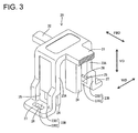
- FIG. 3 is a perspective view showing only a wire pressing portion,
- FIG. 4 is a perspective view showing a state where the wire pressing portion is attached to a mating member,
- FIG. 5 is a perspective view showing a state where a disengagement jig is inserted into a catching hole, and
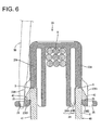
- FIG. 6 is a section showing the state where the disengagement jig is inserted into the catching hole.
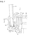
- FIG. 7 is a perspective view showing a procedure of a disengaging operation of inserting a minus driver into a disengagement recess in one further embodiment,
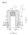
- FIG. 8 is a section showing engaged parts of engaging portions and engaging projections, and
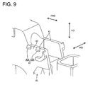
- FIG. 9 is a perspective view of a mating member.
- One preferred embodiment of the present invention is described with reference to FIGS. 1 to 6. A wire cover 1 of a preferred embodiment of the present invention is for bending one or more wires W (actually, a wire group formed by bundling a plurality of wires W, but merely called wires W in the following description) drawn out through a wire draw-out surface of a connector (not shown) attached to a
mating member 40 in a direction different from a draw-out direction and guiding the wires W in a specified (predetermined or predeterminable) direction. FIG. 1 is a bottom view of the wire cover 1, and the unillustrated wires W are arranged at the bottom side of the wire cover 1. - As shown in FIG. 1, the wire cover 1 is provided with a connector-
side fixing portion 10 to be fixed to the connector, awire pressing portion 20 to be fixed to themating member 40 and a connectingportion 30 integrally or unitarily connecting the connector-side fixing portion 10 andwire pressing portion 20. On the other hand, themating member 40 is provided with one or more, preferably a pair of engagingwall portions 41 preferably substantially opposed to each other, and one or more, preferably a pair of engaging projections (corresponding to preferred engageable portions) 42 projecting from one or more surfaces of end portions of the (preferably both) engaging wall portion(s) 41 preferably substantially opposite to the facing surfaces as shown in FIG. 6. In the following description, reference is made to a direction normal to the plane of FIG. 1 concerning vertical direction VD with a back side set as an upper side, reference is made to transverse direction in FIG. 1 concerning forward and backward directions FBD with a shown right side set as a front side, and reference is made to vertical direction in FIG. 1 concerning width direction WD. - The connector-
side fixing portion 10 includes one or more, preferably a pair ofside plates 11 preferably substantially facing each other in width direction WD, and the upper ends of theside plates 11 are connected by anupper end wall 12. One ormore fixing plates 13 projecting substantially backward or along the forward and backward directions FBD are integrally or unitarily formed on the outer side surfaces of the (respective) side plate(s) 11, and one or more fixinggrooves 14 extending substantially upward from the bottom end are formed in the fixing plate(s) 13. The fixinggrooves 14 can fix the connector-side fixing portion 10 to the connector by being engaged with one or more lock projections (not shown) provided on the connector. - As shown in FIG. 2, the connecting
portion 30 includes a flexibleresilient portion 31 extending substantially forward from (preferably the front end edge of) theupper end wall 12, and awire constraining portion 32 coupled to (preferably the front end edge of) theresilient portion 31. The width of theresilient portion 31 preferably is set slightly shorter than a distance between the bothside plates 11 of the connector-side fixing portion 10. Upon being bent toward themating member 40, theresilient portion 31 comes to be arranged between the bothside plates 11 and a bend accommodating portion is formed by the inner side surfaces of the bothside plates 11 and the inner surface of theresilient portion 31. - The
wire constraining portion 32 preferably substantially is rod- or column-shaped and formed substantially not to be resiliently deformable or to have a significantly reduced resiliency as compared to theresilient portion 31. Thiswire constraining portion 32 is to be tied with or fixed to the wires W by a binding band, clamp or the like (not shown). Thus, when thewire pressing portion 20 is bent substantially toward the mating member (toward the front side of the plane of FIG. 1) by resiliently deforming theresilient portion 31, the bent parts of the wires W are at least partly accommodated in the aforementioned bend accommodating portion. - The
wire pressing portion 20 includes a (preferably substantially rectangular)base plate portion 21 having a rear portion (preferably the rear end edge) coupled to thewire constraining portion 32, and (preferably four) side walls projecting downward at the front and/or rear sides of the substantially opposite side edges of thebase plate portion 21. Out of these side walls, the (preferably two) side wall(s) at the front side serve as one or more, preferably a pair of guidingprojections 22 and the one or those at the rear side serve(s) as one or more, preferably a pair of resilient engagingpieces 23. - The (preferably both) guiding projection(s) 22 project(s) downward from the (preferably substantially opposite) sides of (preferably the front end of) the
base plate portion 21 preferably while substantially facing each other. A projecting height of the guidingprojections 22 preferably is set substantially equal to or slightly larger than the diameter of the wires W. Since the lower surface of thebase plate portion 21 is to come substantially in contact with the wires W due to resilient forces of the wires W when the wires W are bent, the wires W can be reliably guided to extend substantially forward or along the forward and backward directions FBD from (preferably the front end of) thebase plate portion 21 by arranging the wires W at least partly adjacent to or between the both guidingprojections 22. - The (preferably both) resilient engaging
pieces 23 include one or more deformation restrictedportions 23A extending downward from the (preferably substantially opposite) side(s) of (preferably the rear end of) thebase plate portion 21 preferably while substantially facing each other, and one or more deformation permittedportions 23B projecting downward from the outer side surfaces of (preferably the bottom ends of) the deformation restrictedportions 23A while being supported only one side. Each deformation permittedportion 23B is comprised of one or more, preferably a pair of supporting arms 23B1 projecting in such a manner as to hold the engagingprojection 42 close thereto or at least partly therebetween, and preferably a bridging portion 23B2 bridging the leading ends of the both supporting arms 23B1 to integrally or unitarily connect them, and is substantially U-shaped as a whole. The upper surface of the bridging portion 23B2 is set at a position lower than the bottom surfaces of the deformation restrictedportions 23A, whereby an engaging hole (corresponding to a preferred engaging portion) 25 is formed by the substantially opposite inner surfaces of the both supporting arms 23B1, the upper surface of the bridging portion 23B2 and the lower surface of the deformation restrictedportion 23A. The engaginghole 25 enables thewire pressing portion 20 to be fixed to themating member 40 by being engaged with the engagingprojection 42. - When the
wire pressing portion 20 is fixed to themating member 40, the lower surface of thebase plate portion 21 receives upward acting resilient repulsive forces from the bent wires W and the lower surfaces of the engagingprojections 42 and the upper surfaces of the bridging portions 23B2 are held substantially in contact with each other. In this state, clearances S are formed between the lower surfaces of the deformation restrictedportions 23A and the upper surfaces of theengaging wall portions 41. The clearances S (FIG. 6) are provided because the upper surfaces of the bridging portions 23B2 make pivotal displacements about the base ends thereof and the bridging portions 23B2 pass positions above those before the displacements upon moving over the engagingprojections 42. Accordingly, the clearances S are set to have such a length as to enable the bridging portions 23B2 to move over the engagingprojections 42 with the lower surfaces of the deformation restrictedportions 23A and the upper surfaces of theengaging wall portions 41 held in contact. - One or more, preferably a pair of
auxiliary walls 24 projecting substantially downward from thebase plate portion 21 preferably while substantially facing each other are formed on the inner side(s) of the (preferably both) resilient engaging piece(s) 23. Eachauxiliary wall 24 is comprised of a facingwall 24 arranged to substantially face the resilient engagingpiece 23 and restrictingwalls 24B for restricting a resilient deformation of the facingwall 24A by extending outward substantially in width direction WD from the front and rear edges of the facingwall 24A, and is in the form of a column having a U-shaped cross section as a whole. The bottom ends of theauxiliary walls 24 are set at such height positions preferably substantially aligned with the bottom ends of the deformation permittedportions 23B. The outer widthwise edges of the restrictingwalls 24B are integrally or unitarily connected with the deformation restrictedportions 23A, whereby the restrictingwalls 24B can restrict resilient deformations of the deformation restrictedportions 23A while permitting only resilient deformations of the deformation permittedportions 23B substantially in width direction WD. Further, resilient forces of the deformation permittedportions 23B become larger than in the case where the deformation restrictedportions 23A and theauxiliary walls 24 are separately formed, wherefore the engagingholes 25 and engagingprojections 42 can be engaged with enhanced forces. It should be noted that a distance between the inner surfaces of the deformation permittedportions 23B and the lateral ends of the restrictingwalls 24B preferably is set substantially equal to or slightly larger than the thickness of theengaging wall portions 41. - A bulging
portion 27 projecting outward substantially in width direction WD is formed on the outer side surface of the bridging portion 23B2 of each deformation permittedportion 23B. This bulgingportion 27 is formed with a catching hole (corresponding to a preferred catching portion) 26 penetrating substantially in vertical direction (projecting direction of the deformation permittedportion 23B). The catchinghole 26 is located at a position which can be seen from the base end side of the resilient engagingpiece 23 and dimensioned such that a minus driver 50 (corresponding to a preferred jig) is at least partly insertable thereinto from the base end side of the resilient engagingpiece 23. Accordingly, the deformation permittedportion 23B can be displaced outward substantially in width direction WD (direction to disengage the engaginghole 25 and engaging projection 42) by at least partly inserting the substantially flat orminus driver 50 from the base end side of the resilient engagingpiece 23 and bringing it into catching engagement with the catchinghole 26. The catchinghole 26 is located at the position which can be seen from the base end side of the resilient engagingpiece 23 because it is difficult to at least partly insert the leading end of theminus driver 50 into the catchinghole 26 even if theminus driver 50 is at least partly inserted from the base end side of the resilient engagingpiece 23 in the case where the catchinghole 26 should be located at a position unseeable from the base end side of the resilient engagingpiece 23. - Next, functions of this embodiment constructed as above are described.
- First, the attachment of the
wire pressing portion 20 to themating member 40 is described. When thewire pressing portion 20 is pushed toward the engagingprojections 42, theresilient portion 31 is resiliently deformed and the wires W are at least partly bent, whereby the wires W come substantially into contact with the lower surface of thebase plate portion 21 by resilient repulsive forces of the wires W. When the wires W are at least partly arranged between the both guidingprojections 22 and thewire pressing portion 20 is further pressed, the engagingwall portions 41 at least partly enter between the deformation permittedportions 23B and theauxiliary walls 24, and the leading ends of the deformation permittedportions 23B move onto the engagingprojections 42 to resiliently deform the deformation permittedportions 23B outward in width direction WD. When the leading ends of the deformation permittedportions 23B move over the engagingprojections 42, the deformation permittedportions 23B are resiliently at least partly restored to engage the engagingholes 25 and engagingprojections 42. In this way, thewire pressing portion 20 is fixed to themating member 40. - Next, the detachment of the
wire pressing portion 20 from themating member 40 is described. The leading end of theminus driver 50 is at least partly inserted into one catchinghole 25 from the base end side of the resilient engagingpiece 23. Then, the leading end of theminus driver 50 is displaced in such a disengaging direction (preferably outward substantially in width direction WD) to disengage the engaginghole 25 and engagingprojection 42. Subsequently, the leading end of theminus driver 50 is or can be at least partly inserted into the other catchinghole 25 from the base end side of the resilient engagingpiece 23 and displaced in the disengaging direction (outward in width direction WD) to disengage the engaginghole 25 and engagingprojection 42, whereby thewire pressing portion 20 can be detached from themating member 40. - As described above, this embodiment has the following effects.
- 1. The disengagement jig or
minus driver 50 is at least partly inserted from the base end side of the resilient engagingpiece 23 to bring the leading end thereof into catching engagement with the catchinghole 26. In this way, the resilient engagingpiece 23 is displaced in a disengaging direction, thereby being able to disengage the catchinghole 25 and engagingprojection 42. Accordingly, the resilient engagingpiece 23 can be detached from themating member 40 by inserting theminus driver 50 from the base end side of the resilient engagingpiece 23. - 2. The engaging
wall portions 41 can be at least partly sandwiched or positioned between the resilient engagingpieces 23 andauxiliary walls 24. Accordingly, the engagingholes 25 and engagingprojections 42 can be held engaged. Even if the resilient engagingpieces 23 should try to be resiliently deformed outward, there is no likelihood that the engagingholes 25 and engagingprojections 42 are easily disengaged since the resilient engagingpieces 23 become more difficult to resiliently deform than in the case where the resilient engagingpieces 23 are provided separately from theauxiliary walls 24. - 3. The depth of the engaging
holes 25 can be increased by thickening the resilient engagingpieces 23 at the sides substantially opposite to theengaging wall portions 41. Accordingly, engaging forces can be improved without reducing the resilient forces of the resilient engagingpieces 23. - Accordingly, to enable a wire pressing portion to be easily detached from a mating member by inserting a disengagement jig from the base end side of a resilient engaging piece of the wire pressing portion, a wire cover 1 is provided with a connector-
side fixing portion 10 to be fixed to a connector, awire pressing portion 20 to be held substantially in contact with one or more wires or cables W, and a connectingportion 30 connecting the connector-side fixing portion 10 andwire pressing portion 20. One or more resilient engagingpieces 23 formed with one or more respective engagingholes 25 project from thewire pressing portion 20, and thewire pressing portion 20 can be fixed to amating member 40 at least partly fitted with the connector by engaging the one or moreengaging holes 25 with one or more respectiveengaging projections 42 provided at themating member 40. At or near the leading ends of the resilient engagingpieces 23 are formed one or more catchingholes 26 used for disengagement, with each of which ajig 50 at least partly inserted from the base end side of the resilient engagingpiece 23 can be brought into catching engagement to displace the resilient engagingpiece 23 in such a direction as to disengage the engaginghole 25 and engagingprojection 42. - The present invention is not limited to the above described and illustrated embodiment. For example, the following embodiments are also embraced by the technical scope of the present invention as defined by the claims. Beside the following embodiments, various changes can be made without departing from the scope and spirit of the present invention as defined by the claims.
- (1) Although the
auxiliary walls 24 are provided in the foregoing embodiment, they may not be provided according to the present invention. - (2) Although the pair of resilient engaging
pieces 23 and the pair ofauxiliary walls 24 are provided in the foregoing embodiment, the resilient engagingpiece 23 andauxiliary wall 24 may be provided either one of the opposite side edges of thebase plate portion 21 according to the present invention. - (3) Although the resilient engaging
pieces 23 andauxiliary walls 24 are integrally or unitarily formed in the foregoing embodiment, the resilient engagingpieces 23 may be formed separately form theauxiliary walls 24 according to the present invention. - (4) Although the catching portions are in the form of catching
holes 26 in the foregoing embodiment, they need not necessarily be through holes and may be formed as recesses with which the disengagement jig can be brought into catching engagement according to the present invention. - (5) Although the engaging portions preferably are in the form of the engaging
holes 25 and the engageable portions preferably are in the form of the engagingprojections 42 in the foregoing embodiment, the engaging portions may be in the form of engaging projections and the engageable portions may be in the form of engaging holes according to the present invention. - One further preferred embodiment of the present invention is described with reference to FIGS. 7 to 9. A wire cover 1 of a further preferred embodiment of the present invention is provided with a
wire pressing portion 20 to be held in contact with one or more bent parts of one or more wires or cables W (actually, a wire group formed by bundling a plurality of wires W, but merely called wires W in the following description) drawn out from a connector (not shown), and thewire pressing portion 20 is to be fixed to amating member 40 to which the connector is attached. As shown in FIG. 8, themating member 40 is provided with one or more, preferably a pair of engagingwall portions 41 facing each other, and one or more, preferably a pair of engagingprojections 42 projecting from one or more surfaces of end portions of the both engagingwall portions 41 preferably substantially opposite to the facing surfaces of the (preferably both) engagingwall portions 41. Each engagingprojection 42 is comprised of one or more, preferably a pair of projections spaced apart by a specified (predetermined or predeterminable) distance. In the following description, reference is made to vertical direction of FIG. 8 concerning vertical direction VD, reference is made to the longitudinal direction of the wires W in FIG. 8 concerning forward and backward directions FBD, and reference is made to transverse direction in FIG. 8 (direction in which the both engagingwall portions 41 face each other) concerning width direction WD. - As shown in FIG. 7, the
wire pressing portion 20 includes abend accommodating portion 20A for at least partly accommodating the bent parts of the wires W, awire constraining portion 20B to be tied with or fixed to the wires W by a binding band, binder, clip or the like (not shown), and alock portion 20C coupled to thebend accommodating portion 20A via thewire constraining portion 20B and to be fixed to themating member 40. Thelock portion 20C is comprised of a (preferably substantially rectangular)base plate portion 21 connected with thewire constraining portion 20B and a pair ofside plates 22 projecting substantially downward from the opposite side edges of thebase plate portion 21, and preferably substantially has a U-shaped cross section as a whole. On the outer side surfaces of the bothside plates 22, one or more, preferably a pair of resilient engagingpieces 23 are formed to project substantially downward from (preferably the bottom ends of) the (preferably both)side plates 22 preferably while substantially facing each other and being supported only at one side. - Each resilient engaging
piece 23 is comprised of one or more, preferably a pair of supportingarms 23A projecting to hold the engaging projection close thereto or at least partly therebetween and an engagingportion 23B projecting from, preferably bridging the leading ends of the both supportingarms 23A preferably to integrally or unitarily couple them, and has a bent or substantially U-shaped cross section as a whole. Thus, the engagingportion 23B is located at a position which can be seen from the base end side of the resilient engagingpiece 23, and a disengagement jig (such as a minus orflat driver 50 to be described later) can be at least partly inserted preferably in such a posture substantially parallel to a projecting direction of the resilient engagingpiece 23. - The distal or upper surface of the engaging
portion 23B is set at a position lower than the bottom surfaces of theside plates 22, whereby an engaginghole 25 is formed by the opposite inner surfaces of the both supportingarms 23A, the upper surface of the engagingportion 23B and the lower surface of theside plate 22. The engaginghole 25 is engageable with the engagingprojection 42 and can fix thewire pressing portion 20 to themating member 40 by the engagement of the upper surface of the engagingportion 23B and the lower surface of the engagingprojection 42. The engagingportion 23B preferably is formed thinner than the supportingarms 23B by having the inner side thereof thinned. Accordingly, the inner surface of the engagingportion 23B is at a specified (predetermined or predeterminable) distance from the outer surface of theengaging wall portion 41. - When the
wire pressing portion 20 is fixed or mounted to themating member 40, the lower surface of thebase plate portion 21 receives upward acting resilient repulsive forces from the bent wires W and the lower surfaces of the engagingprojections 42 and the upper surfaces of the engagingportions 23B are urged towards each other and/or held substantially in contact with each other. In this state, clearances S are formed between the lower surfaces of theside plates 22 and the upper surfaces of theengaging wall portions 41. The clearances S are provided because the upper surfaces of the engagingportions 23B make pivotal displacements about the base ends thereof and the engagingportions 23B pass positions above those before the displacements upon moving over the engagingprojections 42. Accordingly, the clearances S are set to have such a length as to enable the engagingportions 23B to move over the engagingprojections 42 with the lower surfaces of theside plates 22 and the upper surfaces of theengaging wall portions 41 held in contact. - One or more, preferably a pair of
auxiliary walls 24 projecting substantially downward from thebase plate portion 21 preferably while facing each other are formed on the inner sides of the both resilient engagingpieces 23. Eachauxiliary wall 24 preferably is comprised of a facingwall 24A arranged to face theside plate 22 and one or more restrictingwalls 24B for restricting a resilient deformation of the facingwall 24A by extending substantially outward in width direction WD from the front and/or rear portions or edges of the facingwall 24A, and preferably is in the form of a column having a U-shaped cross section as a whole. The bottom ends of theauxiliary walls 24 preferably are set at such height positions substantially aligned with the bottom ends of the resilient engagingpieces 23. The outer widthwise edges of the restrictingwalls 24B are integrally or unitarily connected with theside plate 22, whereby the restrictingwalls 24B can restrict resilient deformations of theside plates 22 while permitting only resilient deformations of the resilient engagingpieces 23 in width direction WD. As a result, engaging forces of the engagingholes 25 and engagingprojections 42 can be more enhanced as compared to the case where theside plates 22 are formed separately from theauxiliary walls 24. It should be noted that a distance between the inner surfaces of the supportingarms 23A and the lateral ends of the restrictingwalls 24B preferably is set substantially equal to or slightly larger than the thickness of theengaging wall portions 41. - As described above, each engaging
projection 42 preferably is comprised of afront projection 42A and arear projection 42B at a specified (predetermined or predeterminable) distance from each other. Adisengagement recess 43 is defined between the bothprojections portion 23B is located at the position which can be seen from the base end side of the resilient engagingpiece 23 through thisdisengagement recess 43. The spacing between the bothprojections portion 23B and the outer surface of theengaging wall portion 41 is set such that the leading end of theminus driver 50 is at least partly insertable. Thus, the resilient engagingpiece 23 can be resiliently displaced in such a direction (preferably substantially outward in width direction WD) to disengage the engaginghole 25 and engagingprojection 42 by at least partly inserting theminus driver 50 from the base end side of the resilient engagingpiece 23 and at least partly inserting the leading end of theminus driver 50 into the clearance between the inner surface of the engagingportion 23B and the outer surface of theengaging wall portion 41 through thedisengagement recess 43. - If the disengaging
recess 43 should be located at a position which cannot be seen from the base end side of the resilient engagingpiece 23, theminus driver 50 cannot be inserted into thedisengagement recess 43. In such a case, it may be thought, for example, to insert theminus driver 50 along the outer surface of one supportingarm 23A (surface substantially opposite to the one facing the other supportingarm 23A) from the base end side of the resilient engagingpiece 23 and at least partly insert the leading end of theminus driver 50 into the clearance between the one supportingarm 23A and engagingwall portion 41 to displace the engagingportion 23B in a disengaging direction. However, a very large force is necessary not only to resiliently deform the one supportingarm 23A, but also to resiliently deform the other supportingarm 23A, thereby deteriorating operability. For this reason, thedisengagement recess 43 is located at the position which can be seen from the base end side of the resilient engagingpiece 23. - Next, functions of this embodiment constructed as above are described.
- First, the attachment of the
wire pressing portion 20 to themating member 40 is described. When thewire pressing portion 20 is pushed substantially toward the engagingprojections 42, the wires W are bent, the bent parts of the wires W are at least partly accommodated into thebend accommodating portion 20A, and the wires W at least partly come substantially into contact with the lower surface of thebase plate portion 21 by resilient repulsive forces of the wires W. When thewire pressing portion 20 is further pressed, the engagingwall portions 41 at least partly enter between the resilient engagingpieces 23 andauxiliary walls 24, and the engagingportions 23B move onto or over the engagingprojections 42 to resiliently deform the resilient engagingpieces 23 in a deforming direction (preferably substantially outward in width direction WD). When the engagingportions 23B move over the engagingprojections 42, the resilient engagingpieces 23 are resiliently at least partly restored to engage the engagingportions 23B and engagingprojections 42. In this way, thewire pressing portion 20 is fixed to themating member 40. - Next, the detachment of the
wire pressing portion 20 from themating member 40 is described. The leading end of theminus driver 50 is at least partly inserted through thedisengagement recess 43 from the base end side of one resilient engagingpiece 23 to at least partly enter the clearance between the engagingportion 23B and engagingwall portion 41. Then, the leading end of theminus driver 50 is displaced in a displacement direction (preferably substantially outward in width direction WD) to disengage the engagingportion 23B and engagingprojection 42. Subsequently, the leading end of theminus driver 50 is or can be at least partly inserted through thedisengagement recess 43 from the base end side of the other resilient engagingpiece 23 to at least partly enter the clearance between the engagingportion 23B and engagingwall portion 41, thereby displacing the resilient engaging piece 23 (preferably substantially outward in width direction WD) to disengage the engagingportion 23B and engagingprojection 42. In this way, thewire pressing portion 20 can be detached from themating member 40. - As described above, this embodiment has the following effects.
- 1. The
minus driver 50 is or can be at least partly inserted from the base end side of the resilient engagingpiece 23 to at least partly insert the leading end thereof into the clearance between the engagingportion 23B andmating member 40 through thedisengagement recess 43. In this way, the engagingportion 23B can be displaced in a disengaging direction to be disengaged from themating member 40. Accordingly, the resilient engagingpiece 23 can be detached from themating member 40 by at least partly inserting theminus driver 50 from the base end side of the resilient engagingpiece 23. - 2. The disengagement recesses 43 can be located at the positions which can be seen from the base end sides of the resilient engaging
pieces 23 with the resilient engagingpieces 23 attached to themating member 40. Further, thedisengagement jig 50 preferably can be at least partly inserted in such a posture substantially parallel to the projecting direction of the resilient engagingpieces 23. Accordingly, the disengaging operation can be more easily performed than in the case where through holes are formed at the leading end side of the resilient engagingpieces 23 and leading end parts of surrounding walls forming the through holes serve as the engaging portions. - 3. The engaging
wall portions 41 can be at least partly sandwiched or positioned between the resilient engagingpieces 23 andauxiliary walls 24. Accordingly, the engagingportions 23B and engagingprojections 42 can be held engaged. Even if the resilient engagingpieces 23 should try to be resiliently deformed outward, there is no likelihood that the engagingportions 23B and engagingprojections 42 are easily disengaged since the resilient engagingpieces 23 become more difficult to resiliently deform than in the case where the resilient engagingpieces 23 are provided separately from theauxiliary walls 24. - Accordingly, to enable a wire pressing portion to be easily detached from a mating member by at least partly inserting a (disengagement) jig from the base end side of a resilient engaging piece of the wire pressing portion, a wire cover 1 is provided with a
wire pressing portion 20 to be brought into contact with one or more bent parts of one or more wires W drawn out from a connector. On the other hand, amating member 40 to or with which the connector is attached or connected includes one or more, preferably a pair of engagingwall portions 41 having one or moreengaging projections 42 and preferably substantially facing each other. One or more resilient engagingpieces 23 project from thewire pressing portion 20 substantially toward the engaging projection(s) 42. Each resilient engagingpiece 23 includes an engagingportion 23B for fixing the resilient engagingpiece 23 to themating member 40 by being engaged with the corresponding engagingprojection 42. Each engagingprojection 42 is formed with at least onedisengagement recess 43 for at least partly receiving the leading end of aminus driver 50 at least partly inserted from the base end side of the resilient engagingpiece 23 so that the engagingportion 23B can be displaced by theminus driver 50 to be disengaged from the engagingprojection 42. - The present invention is not limited to the above described and illustrated embodiment. For example, the following embodiments are also embraced by the technical scope of the present invention as defined by the claims.
- (1) Although the
auxiliary walls 24 are provided in the foregoing embodiment, they may not be provided according to the present invention. - (2) Although the pair of resilient engaging
pieces 23 and the pair ofauxiliary walls 24 are provided in the foregoing embodiment, the resilient engagingpiece 23 andauxiliary wall 24 may be provided either one of the opposite side edges of thebase plate portion 21 according to the present invention. - (3) Although the resilient engaging
pieces 23 andauxiliary walls 24 are integrally or unitarily formed in the foregoing embodiment, the resilient engagingpieces 23 may be formed separately form theauxiliary walls 24 according to the present invention. - (4) Although each engaging projection is comprised of the pair of
projections 42Aprojections - (5) Although the resilient engaging
pieces 23 are U-shaped with open base ends in the foregoing embodiment, they may have a hollow rectangular shape as a whole by closing the base ends thereof according to the present invention. -
- 1 ...
- wire cover
- 10 ...
- connector-side fixing portion
- 20 ...
- wire pressing portion
- 23 ...
- resilient engaging piece
- 23B ...
- engaging portion
- 24 ...
- auxiliary wall
- 25 ...
- engaging hole (engaging portion)
- 26 ...
- catching hole (catching portion)
- 30 ...
- connecting portion
- 40 ...
- mating member
- 41 ...
- engaging wall portion
- 42 ...
- engaging projection (engageable portion)
- 43 ...
- disengagement recess
- 50 ...
- minus driver (jig)
- W ...
- wire
Claims (10)
- A wire cover (1) for bending at least one wire (W) drawn out from a connector in a direction different from a draw-out direction, comprising
a connector-side fixing portion (10) to be fixed to the connector,
a wire pressing portion (20) to be held substantially in contact with the wire (W), and
a connecting portion (30) connecting the connector-side fixing portion (10) and wire pressing portion (20),
wherein the wire pressing portion (20) includes at least one resilient engaging piece (23) projecting therefrom and formed with at least one engaging portion (25) and can be fixed to a mating member (40) at least partly fitted with or to the connector by engaging the at least one engaging portion (25) with at least one engageable portion (42) provided at the mating member (40), and
at least one catching portion (26) for disengagement, with which a jig (50) at least partly inserted from the base end side of the resilient engaging piece (23) is brought into catching engagement to make the resilient engaging piece (23) displaceable in such a direction as to disengage the engaging portion (25) and engageable portion (42). - A wire cover according to claim 1, wherein the jig (50) is to be at least partly inserted from the base end side of the resilient engaging piece (23) to be brought into catching engagement with the at least one catching portion (26).
- A wire cover according to one or more of the preceding claims, wherein:the mating member (40) includes a pair of engaging wall portions (41) each having the engageable portion (42) and substantially facing each other, anda pair of resilient engaging pieces (23) are so provided as to be fittable to the corresponding engaging wall portions (41) from outer sides.
- A wire cover according to claim 3, wherein each resilient engaging piece (23) is integrally or unitarily formed with an auxiliary wall (24) at least partly insertable at an inner side of the corresponding engaging wall portion (41) to sandwich the engaging wall portion (41) between the resilient engaging piece (23) and the auxiliary wall (24).
- A wire cover according to claim 4, wherein the engaging portions (25) of the resilient engaging pieces (24) are substantially in the form of engaging holes (25) and the engageable portions (42) of the engaging wall portions (41) are in the form of engaging projections (42).
- A locking construction for a wire cover (1) including a wire pressing portion (20) to be brought into contact with at least one bent part of at least one wire (W) drawn out from a connector, comprising:at least one engaging projection (42) projecting from a mating member (40) to which the connector is to be attached,at least one resilient engaging piece (23) projecting from the wire pressing portion (20) substantially toward the engaging projection (42),at least one engaging portion (23B) provided on the resilient engaging piece (23) and adapted to fix the resilient engaging piece (23) to the mating member (40) by being engaged with the engaging projection (42), andat least one disengagement recess (43) formed in the engaging projection (42) for at least partly receiving the leading end of a disengagement jig (50), preferably at least partly inserted from the base end side of the resilient engaging piece (23), and causing the jig (50) to displace the engaging portion (23B) for the disengagement from the engaging projection (42).
- A locking construction according to claim 6, wherein a pair of resilient engaging pieces (23) project to hold the engaging projection (42) at least partly therebetween.
- A locking construction according to claim 7, wherein each engaging portion (23B) is substantially U-shaped as a whole by integrally or unitarily connecting at least the leading ends of the both resilient engaging pieces (23).
- A locking construction according to one or more of the preceding claims 6 to 8, wherein:the mating member (40) includes a pair of engaging wall portions (41) each having the engaging projection (42) and substantially facing each other, anda pair of resilient engaging pieces (23) are so provided as to be at least partly fittable to the corresponding engaging wall portions (41) substantially from outer sides.
- A locking construction according to claim 9, wherein each resilient engaging piece (23) is integrally or unitarily formed with at least one auxiliary wall (24) at least partly insertable at an inner side of the corresponding engaging wall portion (41) to sandwich the engaging wall portion (41) between the resilient engaging piece (23) and the auxiliary wall (24).
Applications Claiming Priority (2)
| Application Number | Priority Date | Filing Date | Title |
|---|---|---|---|
| JP2006248456A JP4891714B2 (en) | 2006-09-13 | 2006-09-13 | Wire cover lock structure |
| JP2006248457A JP2008071600A (en) | 2006-09-13 | 2006-09-13 | Electric wire cover |
Publications (3)
| Publication Number | Publication Date |
|---|---|
| EP1901400A2 true EP1901400A2 (en) | 2008-03-19 |
| EP1901400A3 EP1901400A3 (en) | 2008-06-11 |
| EP1901400B1 EP1901400B1 (en) | 2010-08-25 |
Family
ID=38670045
Family Applications (1)
| Application Number | Title | Priority Date | Filing Date |
|---|---|---|---|
| EP07017910A Ceased EP1901400B1 (en) | 2006-09-13 | 2007-09-12 | A wire cover and a locking construction therefor |
Country Status (3)
| Country | Link |
|---|---|
| US (1) | US7458841B2 (en) |
| EP (1) | EP1901400B1 (en) |
| DE (1) | DE602007008658D1 (en) |
Families Citing this family (4)
| Publication number | Priority date | Publication date | Assignee | Title |
|---|---|---|---|---|
| TWM428632U (en) * | 2011-11-18 | 2012-05-01 | Mu-Sheng Lin | Fixing device |
| JP2017059421A (en) * | 2015-09-17 | 2017-03-23 | 住友電装株式会社 | Wire cover |
| CN110694284B (en) * | 2019-09-23 | 2021-12-31 | 深圳市优必选科技股份有限公司 | Building block toy and connecting assembly thereof |
| WO2026059651A1 (en) * | 2024-09-12 | 2026-03-19 | KYOCERA AVX Components Corporation | Low-profile connector |
Citations (1)
| Publication number | Priority date | Publication date | Assignee | Title |
|---|---|---|---|---|
| US20040102082A1 (en) | 2002-11-22 | 2004-05-27 | Sumitomo Wiring Systems, Ltd. | Connector |
Family Cites Families (8)
| Publication number | Priority date | Publication date | Assignee | Title |
|---|---|---|---|---|
| JP2515735Y2 (en) * | 1990-11-21 | 1996-10-30 | 住友電装株式会社 | Wire harness connector cover |
| US6364693B1 (en) * | 1999-05-21 | 2002-04-02 | International Truck And Engine Corp. | Backshell with forced electrical connector orientation |
| JP2004288545A (en) * | 2003-03-24 | 2004-10-14 | Yazaki Corp | Connector protector |
| JP2004348988A (en) | 2003-05-20 | 2004-12-09 | Sumitomo Wiring Syst Ltd | Mounting structure of electric wire cover |
| US7241183B2 (en) * | 2005-01-31 | 2007-07-10 | Delphi Technologies, Inc. | Electrical connector with integrated terminal position assurance and wire cover |
| JP4656579B2 (en) * | 2006-03-29 | 2011-03-23 | 住友電装株式会社 | Connector connection structure and clamp member |
| JP4830770B2 (en) * | 2006-10-06 | 2011-12-07 | 住友電装株式会社 | Wire holder |
| JP4760686B2 (en) * | 2006-11-24 | 2011-08-31 | 住友電装株式会社 | Lock structure |
-
2007
- 2007-09-12 US US11/900,565 patent/US7458841B2/en not_active Expired - Fee Related
- 2007-09-12 EP EP07017910A patent/EP1901400B1/en not_active Ceased
- 2007-09-12 DE DE602007008658T patent/DE602007008658D1/en active Active
Patent Citations (1)
| Publication number | Priority date | Publication date | Assignee | Title |
|---|---|---|---|---|
| US20040102082A1 (en) | 2002-11-22 | 2004-05-27 | Sumitomo Wiring Systems, Ltd. | Connector |
Also Published As
| Publication number | Publication date |
|---|---|
| DE602007008658D1 (en) | 2010-10-07 |
| EP1901400A3 (en) | 2008-06-11 |
| US20080064261A1 (en) | 2008-03-13 |
| EP1901400B1 (en) | 2010-08-25 |
| US7458841B2 (en) | 2008-12-02 |
Similar Documents
| Publication | Publication Date | Title |
|---|---|---|
| US20060252300A1 (en) | Connector for flat cable | |
| JP5651652B2 (en) | Flat conductor electrical connector | |
| JP5282540B2 (en) | Male-female connection structure | |
| EP1909363B1 (en) | A cable holder and a cable holding method | |
| CN104662742A (en) | Connector | |
| JP2004281207A (en) | connector | |
| KR20160118145A (en) | Electrical connector | |
| JP2006179266A (en) | connector | |
| EP1926193B1 (en) | A locking construction, connector provided therewith and unlocking method | |
| EP1901400B1 (en) | A wire cover and a locking construction therefor | |
| CN105490050A (en) | Electric connector with flat conductor | |
| JP2010033978A (en) | Cable connector | |
| EP1801925B1 (en) | A connector | |
| KR101062648B1 (en) | Electrical connector for cable | |
| JP6275104B2 (en) | Connector structure | |
| KR20140016819A (en) | Connector | |
| JP2022023258A (en) | connector | |
| JP5518641B2 (en) | Connectors and retainers | |
| JP2009266497A (en) | Connector | |
| JP5107004B2 (en) | Combined connector | |
| JP4428348B2 (en) | connector | |
| JP4891714B2 (en) | Wire cover lock structure | |
| US20070042629A1 (en) | Latch for connector | |
| JP2020126826A (en) | Housing and connector | |
| EP1437800B1 (en) | Connector for flat cable |
Legal Events
| Date | Code | Title | Description |
|---|---|---|---|
| PUAI | Public reference made under article 153(3) epc to a published international application that has entered the european phase |
Free format text: ORIGINAL CODE: 0009012 |
|
| 17P | Request for examination filed |
Effective date: 20071011 |
|
| AK | Designated contracting states |
Kind code of ref document: A2 Designated state(s): AT BE BG CH CY CZ DE DK EE ES FI FR GB GR HU IE IS IT LI LT LU LV MC MT NL PL PT RO SE SI SK TR |
|
| AX | Request for extension of the european patent |
Extension state: AL BA HR MK YU |
|
| PUAL | Search report despatched |
Free format text: ORIGINAL CODE: 0009013 |
|
| AK | Designated contracting states |
Kind code of ref document: A3 Designated state(s): AT BE BG CH CY CZ DE DK EE ES FI FR GB GR HU IE IS IT LI LT LU LV MC MT NL PL PT RO SE SI SK TR |
|
| AX | Request for extension of the european patent |
Extension state: AL BA HR MK RS |
|
| RIN1 | Information on inventor provided before grant (corrected) |
Inventor name: FUNAYAMA, TOMOYUKITOYOTA JIDOSHA KABUSIKI KAISHA, Inventor name: KOBAYASHI,HIROSHITOYOTA JIDOSHA KABUSHIKI KAISHA, Inventor name: KAKEGAWA, TOMOOTOYOTA JIDOSHA KABUSHIKI KAISHA, Inventor name: NISHIYAMA, SHIGEKITOYOTA JIDOSHA KABUSHIKI KAISHA, Inventor name: KOBAYASHI, TOMOHIKO,SUMITOMO WIRING SYSTEMS LTD. 1 |
|
| RIN1 | Information on inventor provided before grant (corrected) |
Inventor name: KOBAYASHI,HIROSHI Inventor name: NISHIYAMA, SHIGEKI Inventor name: KOBAYASHI, TOMOHIKO Inventor name: FUNAYAMA, TOMOYUKI Inventor name: KAKEGAWA, TOMOO |
|
| 17Q | First examination report despatched |
Effective date: 20081106 |
|
| AKX | Designation fees paid |
Designated state(s): DE FR |
|
| GRAP | Despatch of communication of intention to grant a patent |
Free format text: ORIGINAL CODE: EPIDOSNIGR1 |
|
| GRAS | Grant fee paid |
Free format text: ORIGINAL CODE: EPIDOSNIGR3 |
|
| GRAA | (expected) grant |
Free format text: ORIGINAL CODE: 0009210 |
|
| AK | Designated contracting states |
Kind code of ref document: B1 Designated state(s): DE FR |
|
| REF | Corresponds to: |
Ref document number: 602007008658 Country of ref document: DE Date of ref document: 20101007 Kind code of ref document: P |
|
| PLBE | No opposition filed within time limit |
Free format text: ORIGINAL CODE: 0009261 |
|
| STAA | Information on the status of an ep patent application or granted ep patent |
Free format text: STATUS: NO OPPOSITION FILED WITHIN TIME LIMIT |
|
| 26N | No opposition filed |
Effective date: 20110526 |
|
| REG | Reference to a national code |
Ref country code: DE Ref legal event code: R097 Ref document number: 602007008658 Country of ref document: DE Effective date: 20110526 |
|
| REG | Reference to a national code |
Ref country code: FR Ref legal event code: PLFP Year of fee payment: 10 |
|
| REG | Reference to a national code |
Ref country code: DE Ref legal event code: R084 Ref document number: 602007008658 Country of ref document: DE |
|
| REG | Reference to a national code |
Ref country code: FR Ref legal event code: PLFP Year of fee payment: 11 |
|
| PGFP | Annual fee paid to national office [announced via postgrant information from national office to epo] |
Ref country code: DE Payment date: 20170905 Year of fee payment: 11 Ref country code: FR Payment date: 20170810 Year of fee payment: 11 |
|
| REG | Reference to a national code |
Ref country code: DE Ref legal event code: R119 Ref document number: 602007008658 Country of ref document: DE |
|
| PG25 | Lapsed in a contracting state [announced via postgrant information from national office to epo] |
Ref country code: DE Free format text: LAPSE BECAUSE OF NON-PAYMENT OF DUE FEES Effective date: 20190402 |
|
| PG25 | Lapsed in a contracting state [announced via postgrant information from national office to epo] |
Ref country code: FR Free format text: LAPSE BECAUSE OF NON-PAYMENT OF DUE FEES Effective date: 20180930 |