EP1901392A1 - On-vehicle film antenna apparatus - Google Patents
On-vehicle film antenna apparatus Download PDFInfo
- Publication number
- EP1901392A1 EP1901392A1 EP07017979A EP07017979A EP1901392A1 EP 1901392 A1 EP1901392 A1 EP 1901392A1 EP 07017979 A EP07017979 A EP 07017979A EP 07017979 A EP07017979 A EP 07017979A EP 1901392 A1 EP1901392 A1 EP 1901392A1
- Authority
- EP
- European Patent Office
- Prior art keywords
- film antenna
- case
- electrode
- connecting portion
- vehicle
- Prior art date
- Legal status (The legal status is an assumption and is not a legal conclusion. Google has not performed a legal analysis and makes no representation as to the accuracy of the status listed.)
- Granted
Links
- 239000011521 glass Substances 0.000 claims abstract description 23
- 239000000853 adhesive Substances 0.000 claims description 11
- 230000001070 adhesive effect Effects 0.000 claims description 7
- 238000005304 joining Methods 0.000 claims description 4
- 238000003466 welding Methods 0.000 claims description 3
- 239000004020 conductor Substances 0.000 description 8
- 238000000034 method Methods 0.000 description 5
- 239000011347 resin Substances 0.000 description 5
- 229920005989 resin Polymers 0.000 description 5
- RYGMFSIKBFXOCR-UHFFFAOYSA-N Copper Chemical compound [Cu] RYGMFSIKBFXOCR-UHFFFAOYSA-N 0.000 description 4
- 238000010276 construction Methods 0.000 description 4
- 239000011889 copper foil Substances 0.000 description 4
- 230000008901 benefit Effects 0.000 description 2
- 239000000463 material Substances 0.000 description 2
- 239000002390 adhesive tape Substances 0.000 description 1
- 238000005452 bending Methods 0.000 description 1
- 239000000919 ceramic Substances 0.000 description 1
- 230000006866 deterioration Effects 0.000 description 1
- 239000005357 flat glass Substances 0.000 description 1
- 230000014509 gene expression Effects 0.000 description 1
- 238000004519 manufacturing process Methods 0.000 description 1
- 230000013011 mating Effects 0.000 description 1
- 238000012986 modification Methods 0.000 description 1
- 230000004048 modification Effects 0.000 description 1
- 238000001179 sorption measurement Methods 0.000 description 1
- 239000000758 substrate Substances 0.000 description 1
- 230000000007 visual effect Effects 0.000 description 1
Images




Classifications
-
- H—ELECTRICITY
- H01—ELECTRIC ELEMENTS
- H01Q—ANTENNAS, i.e. RADIO AERIALS
- H01Q1/00—Details of, or arrangements associated with, antennas
- H01Q1/12—Supports; Mounting means
- H01Q1/1271—Supports; Mounting means for mounting on windscreens
-
- H—ELECTRICITY
- H01—ELECTRIC ELEMENTS
- H01Q—ANTENNAS, i.e. RADIO AERIALS
- H01Q1/00—Details of, or arrangements associated with, antennas
- H01Q1/36—Structural form of radiating elements, e.g. cone, spiral, umbrella; Particular materials used therewith
- H01Q1/38—Structural form of radiating elements, e.g. cone, spiral, umbrella; Particular materials used therewith formed by a conductive layer on an insulating support
Definitions
- the present invention relates to an on-vehicle film antenna apparatus, and more particularly to an on-vehicle film antenna apparatus in which a film antenna to be mounted on a glass of a vehicle and a signal output cable are electrically connected to each other.
- a film antenna-side electrode (feed portion) and a case-side electrode (feed portion) are attached to each other using an adhesive material or the like (see e.g. Japanese Utility Model Registration No. 3109077 ).
- an on-vehicle film antenna apparatus 1100 comprised of a socket housing that holds a contact which is to be connected to a connecting terminal portion of a film antenna in a state of being exposed from a bottom surface as shown in FIG. 13 (see e.g. Japanese Unexamined Patent Application Publication No. 2004-82749 ).
- the socket housing is to be stuck to a window glass in a state in which the contact is pressed against the connecting terminal portion of the film antenna.
- the on-vehicle film antenna apparatus 1100 further comprised of a plug housing that can be attached to and detached from the socket housing.
- an on-vehicle film antenna apparatus 1200 in which an upper case is engaged with a lower case in a state in which a circuit board to be connected to a signal output cable and an elastic connecting plate to be connected to the circuit board and a film antenna are interposed between the upper case and the lower case as shown in FIG. 14 (see e.g. Japanese Unexamined Patent Application Publications Nos. 2001-185923 and 2005-80074 ).
- the angle between the connecting case and the film antenna is kept at a fixed angle.
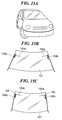
- an on-vehicle film antenna apparatus is desired to be disposed at a position where it looks good, that is, if a case is desired to be disposed at such a position that it is in parallel with any of sides which are boundaries between a glass of a vehicle (FIG. 15A) and an end face of a black ceramic or an interior material being in contact with the glass (hereinafter referred to as the outer periphery of the glass) and that a film antenna is substantially horizontal when the glass is mounted in a vehicle (see FIG. 15C), when the on-vehicle film antenna apparatus fixed at a fixed angle is mounted in a plurality of types of vehicles, the on-vehicle film antenna apparatus cannot be disposed at the position at which it looks good in some vehicles.
- a film antenna 100a is not substantially horizontal but inclined (see the mounted state on the left side in FIG. 15B), and conversely, if a film antenna 100a is disposed substantially horizontal, a case 100b is not substantially parallel or substantially vertical to the side of the outer periphery of the glass 101 but inclined (see the mounted state on the right side in FIG. 15B).
- the on-vehicle film antenna apparatus 1100 (FIG. 13), however, has the problem that, since the film antenna is stuck to the bottom thereof using an adhesive agent or the like to electrically connect the feeding portion of the film antenna and the contact with each other, a connection failure will occur due to deterioration of the adhesive agent or the like.
- the on-vehicle film antenna apparatus 1200 (FIG. 14) is configured to have the film antenna sandwiched therein, a connection failure does not occur unlike the on-vehicle film antenna apparatus 1100.
- much costs are required due to the use of the above-mentioned washer and components such as nuts and bolts for screwing, and moreover, a mounting process is complicated since the on-vehicle film antenna apparatus 1200 has a complicated structure.
- an on-vehicle film antenna apparatus comprising a case that electrically connects an electric connecting portion of a film antenna to be mounted on a glass of a vehicle and a signal output cable to each other, wherein the case comprises a first case member, a second case member, and a case joining unit that joins the first case member and the second case member in opposed relation to each other when the case is assembled, the first case member comprises an electrode for electric connection to the electric connecting portion of the film antenna, and a cable connecting portion for electric connection to the electrode and for electric connection to the signal output cable, the second case member comprises an electrode opposing member at a location opposed to the electrode when the case is assembled, and the first case member and/or the second case member comprise a positioning unit that rotatably positions the electric connecting portion of the film antenna on the electrode.
- the film antenna can be rotatably mounted in the case of the on-vehicle film antenna apparatus while ensuring electric connection between the electrode inside the case and the film antenna, and the structure of the on-vehicle film antenna apparatus can be simplified.
- the electric connecting portion of the film antenna can be disposed between the electrode and the electrode opposing member when the case is assembled.
- the electric connecting portion of the film antenna can be electrically connected with the electrode and in pressure contact with the electrode, and further the positioning unit can rotatably position the film antenna in a reliable manner.
- the electrode opposing member can comprise an elastic member.
- the on-vehicle film antenna apparatus can further comprise an elastic member disposed between the electrode and the first case member.
- the electrode can comprise a conductive elastic member on a surface that is electrically connected to the electric connecting portion of the film antenna.
- case joining unit can be implemented by at least one of a hinge, a latch, a clipping structure, a screwing structure, adhesion, welding, and adhesive taping.
- a circular through hole can be formed in substantially a central part of the electric connecting portion of the film antenna, and the positioning unit can comprise a projection provided above the electrode and/or the electrode opposing member and comprising a circular outer periphery having substantially the same size as a size of the through hole, the projection being inserted into the through hole when the case is assembled.
- the projection can be formed on one of the electrode and the electrode opposing member, and the positioning unit can comprise a circular concave portion formed in substantially a central part of the other one of the electrode and the electrode opposing member and having substantially the same diameter as an outer diameter of the projection, the projection being inserted into the concave portion when the case is assembled.
- an arc shape can be formed at a part of an outer periphery of the electric connecting portion of the film antenna, and a through hole having, as a part of a boundary, an arc with a predetermined radius formed with a center point of the arc shape at the nucleus is formed in the electric connecting portion of the film antenna, and the positioning unit can comprise a projection that is inserted into the through hole and comes into contact with the arc as the part of the boundary when the case is assembled, and a guide portion that is formed around of the electrode and/or the electrode opposing member of the case and, at least at two points, comes into contact with the part of the outer periphery of the electric connecting portion of the film antenna at which the arc shape is formed, when the case is assembled.
- an arc shape can be formed at a part of an outer periphery of the electric connecting portion of the film antenna
- the positioning unit can comprise a guide portion that is formed around of the electrode and/or the electrode opposing member and, at least at three points, comes into contact with the part of the outer periphery of the electric connecting portion of the film antenna at which the arc shape is formed, when the case is assembled.
- an arc shape coming into contact with the part of the outer periphery of the electric connecting portion of the film antenna at which the arc shape is formed can be formed at a part of an outer periphery of the guide portion.
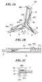
- FIGS. 1A to 1C are views useful in explaining the construction of an on-vehicle film antenna apparatus according to an embodiment of the present invention, in which FIG. 1A is a perspective view showing a state in which a case is opened, FIG. 1B is a cross-sectional view showing a first case member, and FIG. 1C is a longitudinal sectional view showing a state in which the case is closed;
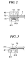
- FIG. 2 is a view showing a first variation of the on-vehicle film antenna apparatus in FIG. 1;
- FIG. 3 is a view showing a second variation of the on-vehicle film antenna apparatus
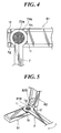
- FIG. 4 is a view showing a third variation of the on-vehicle film antenna apparatus
- FIG. 5 is a view showing a fourth variation of the on-vehicle film antenna apparatus
- FIG. 6 is a view useful in explaining how a film antenna appearing in FIG. 5 is adjusted in position through rotation;
- FIG. 7 is a view showing a fifth variation of the on-vehicle film antenna apparatus
- FIG. 8 is a view showing a sixth variation of the on-vehicle film antenna apparatus
- FIG. 9 is a view showing a seventh variation of the on-vehicle film antenna apparatus.
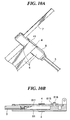
- FIGS. 10 and 10B are views useful in explaining an eighth variation of the on-vehicle film antenna apparatus, in which FIG. 10A is a perspective view showing the on-vehicle film antenna apparatus with its case closed as viewed from below, and FIG. 10B is a cross-sectional view showing the first case member;
- FIG. 11 is a perspective view showing the on-vehicle film antenna apparatus with its case closed as viewed from above;
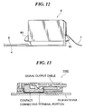
- FIG. 12 is a view showing a ninth variation of the on-vehicle film antenna apparatus
- FIG. 13 is a view showing the construction of a conventional on-vehicle film antenna apparatus
- FIG. 14 is a view showing the construction of a variation of the conventional on-vehicle film antenna apparatus.
- FIGS. 15A to 15C are views useful in explaining how the conventional on-vehicle film antenna apparatus is mounted on a vehicle, in which FIG. 15A is an overall view showing a vehicle body on which the on-vehicle film antenna apparatus is mounted, FIG. 15B is a view showing the on-vehicle film antenna apparatus which is mounted on a glass surface of the vehicle in a state which it does not look good, and FIG. 15C is a view showing the on-vehicle film antenna apparatus which is mounted on a glass surface of a vehicle in a state in which it looks good.
- FIGS. 1A to 1C are views schematically showing the construction of an on-vehicle film antenna apparatus according to an embodiment of the present invention.
- the on-vehicle film antenna apparatus 100 is comprised of a case 8 that electrically connects a film antenna 7 to be mounted on a glass of a vehicle and a signal output cable 3 to each other.
- the film antenna 7 is comprised of a resin film 70, an antenna element 71 that is formed on a surface of the resin film 70 and comprised of a linear conductor, and an electrode 72 that is disposed on a surface of an end 73 of the resin film 70 and connected to the antenna element 71.
- the end 73 of the resin film 70 and the electrode 72 of the antenna element 71 constitute an electric connecting portion 74 of the film antenna 7.
- a circular through hole is formed in the central part of the electric connecting portion 74.
- the length and shape of the antenna element 71 can be arbitrarily determined according to purposes. Where a wavelength to be received is ⁇ , and the velocity of propagation arising from the presence of a glass to which the film antenna 7 is attached is k, it is preferred that the length of the antenna element 71 is k . ⁇ /4.
- the case 8 is, for example, 8 mm wide and 36 mm long and comprised of a first case member 81 and a second case member 82 that can be opened and closed via latches 84a and 84b.
- the film antenna 7 is positioned and fixed between the first case member 81 and the second case member 82.
- the two case members 81 and 82 are connected to each other via a hinge structure 826 and provided with the latches 84a and 84b, respectively, so that they can be opened and closed, there is no intention to limit the invention to this, and the case 8 may be arbitrarily constructed insofar as it can be opened and closed.
- the two case members 81 and 82 may be connected to each other using a thin metallic member or a thin resin member that can freely bend, and the two case member 81 and 82 may be joined to each other using a hooking structure, a screwing structure, a clipping structure, or the like, or by adhesion, welding, or adhesive taping without using the latches 84a and 84b. If the first case member 81 and the second case member 82 are joined to each other by latching, hooking, screwing, or clipping, the case 8 can be opened and closed, whereby the film antenna 7 can be detachably mounted in the case 8. Moreover, the case 8 may be simply constructed without using components such as washers, making it easier to assemble the case 8.
- the first case member 81 and the second case member 82 may be adhered and fixed to each other so that they cannot be detached from each other.
- the first case member 81 has therein a cable lead-out groove 812 from which the signal output cable 3 is led out, and a circuit board 811 (FIG. 1B) that is provided in the cable lead-out groove 812 and electrically connected to a central conductor and an external conductor of the signal output cable 3.
- the circuit board 811 has a role in electrically connecting the central conductor of the signal output cable 3 to an electrode 813, described later, disposed on the first case member 81 and electrically connecting the external conductor of the signal output cable 3 to a grounding structure, not shown.
- an amplifier may be mounted on the circuit board 811.
- the signal output cable 3 may be directly connected to the circuit substrate 811, or the signal output cable 3 and the circuit board 811 may be electrically connected to each other via a connector mounted on a connector terminal provided in place of the cable lead-out groove 812.
- the first case member 81 is comprised of a pin 816 that has a circular outer edge substantially the same size as the size of the through hole, not shown, formed in substantially the central part of the electric connecting portion 74 of the film antenna 7 and is a cylindrical projection that can be inserted into the through hole, and the electrode 813 that is formed around the pin 816.
- the pin 816 and the electrode 813 are provided on a surface of the first case member 81 which is jointed to the second case member 82.
- the outer diameter of the pin 816 has such a circular outer edge that it is able to be inserted into the above-mentioned through hole, not shown, and has substantially the same diameter as the diameter of the through hole (for example, the diameter of the through hole is slightly larger than the outer diameter of the pin 816, and a difference in diameter between them is 1 mm or less).
- the pin 816 Since the pin 816 has such an outer diameter, the electric connecting portion 74 of the film antenna can be positioned with little play.
- the second case member 82 is comprised of an electrode opposing member 825 that rotatably fixes the electric connecting portion 74 positioned as described above when the case 8 has been closed and is provided on a surface of the second case member 82 which is joined to the first case member 81.
- the film antenna 7 can be rotatably mounted in the case 8 while securing electric connection between the electrode 813 inside the case 8 and the electrode 72, which is a part of the electric connecting portion 74 of the film antenna 7, to realize a simplified structure.
- a circular concave portion 822 into which the pin 816 can be inserted and which has substantially the same diameter as the outer diameter of the pin 816.
- the pin 816 is provided on the electrode 813 side, and the concave portion 822 is provided on the electrode opposing member 825 side, there is no intention to limit the invention to this, but a concave portion may be provided on the electrode 813 side, and a pin may be provided on the electrode opposing member 825 side.
- pins may be provided on both the electrode 813 side and the electrode opposing member 825 side, and when the case 8 has been closed, distal ends of the two pins may be brought into contact with each other.
- contacting surfaces of the two pins may be horizontal, oblique, or curved with respect to the pins, or a convex surface of one of the pins and a concave surface of the other one of the pins may be in contact with each other.
- a pin may be provided on one of the electrode 813 side and the electrode opposing member 825 side, and no pin may be provided on the other one of the electrode 813 side and the electrode opposing member 825 side, and when the case 8 has been closed, the pin may be brought into contact with the electrode 813 or the electrode opposing member 825 which is provided with no concave portion.
- the electrode 813 and the circuit board 811 are configured as an integral unit.
- the central conductor of the signal output cable 3 and the electrode 813 can be electrically connected to each other via the circuit board 811.
- the case 8 of the on-vehicle film antenna apparatus 100 is comprised of the first case member 81 and the second case member 82 that can be opened and closed, and the electrode 813 that is connected, via the circuit board 811, to the central conductor of the signal output cable 3 led into the first case member 81 is formed around the pin 816 that positions the electric connecting portion 74 of the film antenna 7.
- the electrode 72 of the antenna element 71 which is a part of the electric connecting portion 74 of the film antenna 7 positioned by the pin 816, and the electrode 813 can be electrically connected to each other.
- the electrode opposing member 825 of the second case member 82 fixes the positioned electric connecting portion 74 when the case 8 has been closed.
- the electrode opposing member 825 is comprised of an elastic member such as a sponge as shown in FIG. 1C, an elastic member 1d is provided on an underside of the circuit board 811 as shown in FIG. 2, or an elastic member is provided between the electrodes 813 and 72 as shown in FIG. 3.
- the electrode opposing member 825 is comprised of an elastic member such as a sponge as shown in FIG. 1C, an elastic member 1d is provided on an underside of the circuit board 811 as shown in FIG. 2, or an elastic member is provided between the electrodes 813 and 72 as shown in FIG. 3.
- the elastic member should not necessarily be a sponge, but rubber or the like may be used; preferably, a conductive elastic member is used in a case where it is provided between the electrodes 813 and 72.
- a conductive elastic member include conductive rubber.
- a surface of the electrode 813 may be covered with an elastic member 1e made of conductive rubber, and an elastic member may be provided on the electric connecting portion 74 of the film antenna 7. This will make it possible to electrically connect the electrodes 813 and 72 to each other in a pressurized state via the elastic member le when the electric connecting portion 74 has been positioned after the case 8 had been closed.
- an electric connecting portion 74c of the film antenna 7 may have an outer periphery which is partially arc-shaped and have an arc-shaped hole 7c formed a predetermined distance away from the center of the arc-shape, and the first case member 81 may have positioning means comprised of a cylindrical concave portion 817 that can be inserted into the arc-shaped hole 7c, and a guide portion 1k formed around the electrode 813, not shown.
- the film antenna 7 can be positioned while ensuring electric connection between the electrode 72c of the film antenna 7 and the electrode 813 inside the case 8.
- the hole 7c is not limited to the present embodiment, and the hole 7c may have any shape insofar as it is partially arc-shaped.
- the hole 7c may be a through hole 816a formed in substantially the center of the electric connecting portion 74 of the film antenna 7 as shown in FIG. 8.
- the convex portion 817 is not limited to the present embodiment and may have any shape insofar as it can be inserted into the hole 7c and has a part that comes into contact with the above-mentioned arc-shaped portion of the hole 7c when inserted into the hole 7c.
- the convex portion 817 may be changed to a semicircular convex portion 817a having an arc-shaped portion that comes into contact with the arc-shaped portion of the through hole 816a when inserted into the through hole 816a.
- a cylindrical convex portion that can be inserted into the arc-shaped hole 7c and a guide portion formed around the electrode opposing member 825 may be provided in the second case member 82.
- one or both of a convex portion and a guide portion may be provided in both the first case member 81 and the second case member 82.
- the electric connecting portion 74a of the film antenna 7 may be configured to have an outer periphery that is partially arc-shaped, and the first case member 81 may be configured to have positioning means comprised of guide portions 1h, 1i, 1f, and 1g formed around the electrode 813, not shown.
- the film antenna 7 is positioned by assembling the case 8 in a state in which at least three points of the outer periphery of the electric connecting portion 74a of the film antenna 7 are in contact with the guide portions 1h, 1i, 1f, and 1g.
- the film antenna 7 may be positioned using the pin 816 (FIG. 1A) as well as the above-mentioned guide portions.
- the second case member 2 may have guide portions formed around the electrode opposing member 825.
- the second case member 2 may have a cylindrical pin that can be inserted into the above-mentioned through hole, and the electrode opposing member 825 formed around the pin may be provided on the surface of the second case member 2 which is joined to the first case member 81.
- the first case member 81 may have an arc-shaped guide portion 1j formed around the electrode 813, not shown, with the central part of the electrode 813 at the nucleus.
- the film antenna 7 can be positioned in a more reliable manner by assembling the case 8 in a state in which a part of the outer periphery of the electric connecting portion 74 of the film antenna 7 is in contact with the guide portion 1j.
- the second case member 82 may have a guide portion formed around the electrode opposing member 825.
- the on-vehicle film antenna apparatus 100 is mounted on the vehicle by fixing the case 8 to the vehicle body or the glass surface
- a fixing method therefor is not limited.
- an adsorption method using an adhesive tape, an adhesive agent, or a sucking disc, or the like is used to fix the case 8 to the glass surface or the vehicle body.
- the case 8 may be fixed to the vehicle body using a conductive adhesive agent, or it may be fastened to the vehicle body by screws.
- a copper foil 4 that extends from an underside of the first case member 81 to the vehicle body as shown in FIG. 10A and disposed between the first case member 81 and the circuit board 811 as shown in FIG. 10B.
- the copper foil 4 and the external conductor of the signal output cable 3 are connected to each other via the circuit board 811.
- a ground can be reliably established for the signal output cable 3 by the copper foil 4.
- an adhesive label 41 may be attached to the mating surface of the first case member 81 and the second case member 82.
- the adhesive label 41 is labeled as "CAUTION"
- a user can be prevented from opening the case 8 by mistake.
- a convex portion 83 may be provided on a side of the first case member 81 and directly below the positioned film antenna 7.
- the on-vehicle film antenna apparatus 100 according to the present embodiment is suitably used as a TV antenna, more particularly, a digital TV antenna (with frequencies 470 to 770 MHz).
- the on-vehicle film antenna apparatus 100 according to the present embodiment may be mounted at any location insofar as it is on a glass of a vehicle.
- the on-vehicle film antenna apparatus 100 according to the present embodiment may be mounted on any glass of a vehicle such as a front glass, a rear glass, or a side glass.
- an antenna system may be of a diversity type.
Landscapes
- Support Of Aerials (AREA)
- Details Of Aerials (AREA)
- Fittings On The Vehicle Exterior For Carrying Loads, And Devices For Holding Or Mounting Articles (AREA)
Abstract
Description
- The present invention relates to an on-vehicle film antenna apparatus, and more particularly to an on-vehicle film antenna apparatus in which a film antenna to be mounted on a glass of a vehicle and a signal output cable are electrically connected to each other.
- Conventionally, in a case where a film antenna (particularly, a universal product to be retrofitted) is mounted on a glass surface of a vehicle, a film antenna-side electrode (feed portion) and a case-side electrode (feed portion) are attached to each other using an adhesive material or the like (see e.g. Japanese Utility Model Registration
No. 3109077 - Also, in recent years, there have been used an on-vehicle
film antenna apparatus 1100 comprised of a socket housing that holds a contact which is to be connected to a connecting terminal portion of a film antenna in a state of being exposed from a bottom surface as shown in FIG. 13 (see e.g.Japanese Unexamined Patent Application Publication No. 2004-82749 film antenna apparatus 1100 further comprised of a plug housing that can be attached to and detached from the socket housing. There have been also used an on-vehiclefilm antenna apparatus 1200 in which an upper case is engaged with a lower case in a state in which a circuit board to be connected to a signal output cable and an elastic connecting plate to be connected to the circuit board and a film antenna are interposed between the upper case and the lower case as shown in FIG. 14 (see e.g.Japanese Unexamined Patent Application Publications Nos. 2001-185923 2005-80074 - Also, there has been disclosed a method in which a feeding portion of a film antenna and a feeding portion inside an on-vehicle film antenna apparatus are fastened to each other by a screw with a conductive washer interposed therebetween and held under pressure so as to ensure electric connection between them, and a connecting portion of a case and the feeding portion of the film antenna are fixed in position by inserting a positioning boss therein so as to reliably position them without resort to visual check (see e.g.
Japanese Unexamined Patent Application Publication No. 2001-185923 - However, according to any of the above-mentioned on-vehicle film antennas, the angle between the connecting case and the film antenna is kept at a fixed angle.
- For this reason, if an on-vehicle film antenna apparatus is desired to be disposed at a position where it looks good, that is, if a case is desired to be disposed at such a position that it is in parallel with any of sides which are boundaries between a glass of a vehicle (FIG. 15A) and an end face of a black ceramic or an interior material being in contact with the glass (hereinafter referred to as the outer periphery of the glass) and that a film antenna is substantially horizontal when the glass is mounted in a vehicle (see FIG. 15C), when the on-vehicle film antenna apparatus fixed at a fixed angle is mounted in a plurality of types of vehicles, the on-vehicle film antenna apparatus cannot be disposed at the position at which it looks good in some vehicles.
- For example, as shown in FIG. 15B, if a
case 100b is disposed substantially parallel with or substantially vertical to one side of the outer periphery of aglass 101 of a vehicle, afilm antenna 100a is not substantially horizontal but inclined (see the mounted state on the left side in FIG. 15B), and conversely, if afilm antenna 100a is disposed substantially horizontal, acase 100b is not substantially parallel or substantially vertical to the side of the outer periphery of theglass 101 but inclined (see the mounted state on the right side in FIG. 15B). - This problem was solved by manufacturing an on-vehicle film antenna apparatus of which fixed angle was adjusted according to the type of vehicle on which they were to be mounted.
- The on-vehicle film antenna apparatus 1100 (FIG. 13), however, has the problem that, since the film antenna is stuck to the bottom thereof using an adhesive agent or the like to electrically connect the feeding portion of the film antenna and the contact with each other, a connection failure will occur due to deterioration of the adhesive agent or the like.
- On the other hand, since the on-vehicle film antenna apparatus 1200 (FIG. 14) is configured to have the film antenna sandwiched therein, a connection failure does not occur unlike the on-vehicle
film antenna apparatus 1100. However, much costs are required due to the use of the above-mentioned washer and components such as nuts and bolts for screwing, and moreover, a mounting process is complicated since the on-vehiclefilm antenna apparatus 1200 has a complicated structure. - Moreover, there is the problem that the method in which the angle at which the on-vehicle film antenna apparatus is fixed is adjusted according to the type of vehicle as shown in FIG. 15B so as to enhance the appearance of the on-vehicle film antenna apparatus is not universal.
- It is an object of the present invention to provide an on-vehicle film antenna apparatus of which film antenna can be rotatably mounted in a case of the on-vehicle film antenna apparatus while ensuring electric connection between an electrode inside the case and the film antenna and which has a simplified structure.
- To attain the above object, in a first aspect of the present invention, there is provided an on-vehicle film antenna apparatus comprising a case that electrically connects an electric connecting portion of a film antenna to be mounted on a glass of a vehicle and a signal output cable to each other, wherein the case comprises a first case member, a second case member, and a case joining unit that joins the first case member and the second case member in opposed relation to each other when the case is assembled, the first case member comprises an electrode for electric connection to the electric connecting portion of the film antenna, and a cable connecting portion for electric connection to the electrode and for electric connection to the signal output cable, the second case member comprises an electrode opposing member at a location opposed to the electrode when the case is assembled, and the first case member and/or the second case member comprise a positioning unit that rotatably positions the electric connecting portion of the film antenna on the electrode.
- With this arrangement, the film antenna can be rotatably mounted in the case of the on-vehicle film antenna apparatus while ensuring electric connection between the electrode inside the case and the film antenna, and the structure of the on-vehicle film antenna apparatus can be simplified.
- Also, the electric connecting portion of the film antenna can be disposed between the electrode and the electrode opposing member when the case is assembled.
- With this arrangement, the electric connecting portion of the film antenna can be electrically connected with the electrode and in pressure contact with the electrode, and further the positioning unit can rotatably position the film antenna in a reliable manner.
- Also, the electrode opposing member can comprise an elastic member.
- Also, the on-vehicle film antenna apparatus can further comprise an elastic member disposed between the electrode and the first case member.
- Also, the electrode can comprise a conductive elastic member on a surface that is electrically connected to the electric connecting portion of the film antenna.
- Also, the case joining unit can be implemented by at least one of a hinge, a latch, a clipping structure, a screwing structure, adhesion, welding, and adhesive taping.
- Also, a circular through hole can be formed in substantially a central part of the electric connecting portion of the film antenna, and the positioning unit can comprise a projection provided above the electrode and/or the electrode opposing member and comprising a circular outer periphery having substantially the same size as a size of the through hole, the projection being inserted into the through hole when the case is assembled.
- Also, the projection can be formed on one of the electrode and the electrode opposing member, and the positioning unit can comprise a circular concave portion formed in substantially a central part of the other one of the electrode and the electrode opposing member and having substantially the same diameter as an outer diameter of the projection, the projection being inserted into the concave portion when the case is assembled.
- Also, an arc shape can be formed at a part of an outer periphery of the electric connecting portion of the film antenna, and a through hole having, as a part of a boundary, an arc with a predetermined radius formed with a center point of the arc shape at the nucleus is formed in the electric connecting portion of the film antenna, and the positioning unit can comprise a projection that is inserted into the through hole and comes into contact with the arc as the part of the boundary when the case is assembled, and a guide portion that is formed around of the electrode and/or the electrode opposing member of the case and, at least at two points, comes into contact with the part of the outer periphery of the electric connecting portion of the film antenna at which the arc shape is formed, when the case is assembled.
- Also, an arc shape can be formed at a part of an outer periphery of the electric connecting portion of the film antenna, and the positioning unit can comprise a guide portion that is formed around of the electrode and/or the electrode opposing member and, at least at three points, comes into contact with the part of the outer periphery of the electric connecting portion of the film antenna at which the arc shape is formed, when the case is assembled.
- Also, an arc shape coming into contact with the part of the outer periphery of the electric connecting portion of the film antenna at which the arc shape is formed can be formed at a part of an outer periphery of the guide portion.
- The above and other objects, features, and advantages of the invention will become more apparent from the following detained description taken in conjunction with the accompanying drawings.
- FIGS. 1A to 1C are views useful in explaining the construction of an on-vehicle film antenna apparatus according to an embodiment of the present invention, in which FIG. 1A is a perspective view showing a state in which a case is opened, FIG. 1B is a cross-sectional view showing a first case member, and FIG. 1C is a longitudinal sectional view showing a state in which the case is closed;
- FIG. 2 is a view showing a first variation of the on-vehicle film antenna apparatus in FIG. 1;
- FIG. 3 is a view showing a second variation of the on-vehicle film antenna apparatus;
- FIG. 4 is a view showing a third variation of the on-vehicle film antenna apparatus;
- FIG. 5 is a view showing a fourth variation of the on-vehicle film antenna apparatus;
- FIG. 6 is a view useful in explaining how a film antenna appearing in FIG. 5 is adjusted in position through rotation;
- FIG. 7 is a view showing a fifth variation of the on-vehicle film antenna apparatus;
- FIG. 8 is a view showing a sixth variation of the on-vehicle film antenna apparatus;
- FIG. 9 is a view showing a seventh variation of the on-vehicle film antenna apparatus;
- FIGS. 10 and 10B are views useful in explaining an eighth variation of the on-vehicle film antenna apparatus, in which FIG. 10A is a perspective view showing the on-vehicle film antenna apparatus with its case closed as viewed from below, and FIG. 10B is a cross-sectional view showing the first case member;
- FIG. 11 is a perspective view showing the on-vehicle film antenna apparatus with its case closed as viewed from above;
- FIG. 12 is a view showing a ninth variation of the on-vehicle film antenna apparatus;
- FIG. 13 is a view showing the construction of a conventional on-vehicle film antenna apparatus;
- FIG. 14 is a view showing the construction of a variation of the conventional on-vehicle film antenna apparatus; and
- FIGS. 15A to 15C are views useful in explaining how the conventional on-vehicle film antenna apparatus is mounted on a vehicle, in which FIG. 15A is an overall view showing a vehicle body on which the on-vehicle film antenna apparatus is mounted, FIG. 15B is a view showing the on-vehicle film antenna apparatus which is mounted on a glass surface of the vehicle in a state which it does not look good, and FIG. 15C is a view showing the on-vehicle film antenna apparatus which is mounted on a glass surface of a vehicle in a state in which it looks good.
- The present invention will now be described in detail with reference to the drawings showing preferred embodiments thereof. It should be noted that the relative arrangement of the components, the numerical expressions and numerical values set forth in these embodiments do not limit the scope of the present invention unless it is specifically stated otherwise.
- The present invention will now be described in detail with reference to the drawings showing a preferred embodiment thereof.
- FIGS. 1A to 1C are views schematically showing the construction of an on-vehicle film antenna apparatus according to an embodiment of the present invention.
- As shown in FIG. 1A, the on-vehicle
film antenna apparatus 100 is comprised of acase 8 that electrically connects afilm antenna 7 to be mounted on a glass of a vehicle and asignal output cable 3 to each other. - The
film antenna 7 is comprised of aresin film 70, anantenna element 71 that is formed on a surface of theresin film 70 and comprised of a linear conductor, and anelectrode 72 that is disposed on a surface of anend 73 of theresin film 70 and connected to theantenna element 71. Theend 73 of theresin film 70 and theelectrode 72 of theantenna element 71 constitute an electric connectingportion 74 of thefilm antenna 7. In the central part of the electric connectingportion 74, a circular through hole, not shown, is formed. - Here, the length and shape of the
antenna element 71 can be arbitrarily determined according to purposes. Where a wavelength to be received is λ, and the velocity of propagation arising from the presence of a glass to which thefilm antenna 7 is attached is k, it is preferred that the length of theantenna element 71 is k . λ/4. - The
case 8 is, for example, 8 mm wide and 36 mm long and comprised of afirst case member 81 and asecond case member 82 that can be opened and closed vialatches film antenna 7 is positioned and fixed between thefirst case member 81 and thesecond case member 82. Although in the present embodiment, the twocase members hinge structure 826 and provided with thelatches case 8 may be arbitrarily constructed insofar as it can be opened and closed. Thus, the twocase members case member latches first case member 81 and thesecond case member 82 are joined to each other by latching, hooking, screwing, or clipping, thecase 8 can be opened and closed, whereby thefilm antenna 7 can be detachably mounted in thecase 8. Moreover, thecase 8 may be simply constructed without using components such as washers, making it easier to assemble thecase 8. - It should be noted that once the
film antenna 7 has been positioned, thefirst case member 81 and thesecond case member 82 may be adhered and fixed to each other so that they cannot be detached from each other. - The
first case member 81 has therein a cable lead-outgroove 812 from which thesignal output cable 3 is led out, and a circuit board 811 (FIG. 1B) that is provided in the cable lead-outgroove 812 and electrically connected to a central conductor and an external conductor of thesignal output cable 3. Thecircuit board 811 has a role in electrically connecting the central conductor of thesignal output cable 3 to anelectrode 813, described later, disposed on thefirst case member 81 and electrically connecting the external conductor of thesignal output cable 3 to a grounding structure, not shown. It should be noted that an amplifier may be mounted on thecircuit board 811. In thecase 8, thesignal output cable 3 may be directly connected to thecircuit substrate 811, or thesignal output cable 3 and thecircuit board 811 may be electrically connected to each other via a connector mounted on a connector terminal provided in place of the cable lead-outgroove 812. - The
first case member 81 is comprised of apin 816 that has a circular outer edge substantially the same size as the size of the through hole, not shown, formed in substantially the central part of the electric connectingportion 74 of thefilm antenna 7 and is a cylindrical projection that can be inserted into the through hole, and theelectrode 813 that is formed around thepin 816. Thepin 816 and theelectrode 813 are provided on a surface of thefirst case member 81 which is jointed to thesecond case member 82. With this arrangement, the electric connectingportion 74 of thefilm antenna 7 can be positioned merely by passing thepin 816 through the through hole, not shown, of the electric connectingportion 74. - It is preferred that the outer diameter of the
pin 816 has such a circular outer edge that it is able to be inserted into the above-mentioned through hole, not shown, and has substantially the same diameter as the diameter of the through hole (for example, the diameter of the through hole is slightly larger than the outer diameter of thepin 816, and a difference in diameter between them is 1 mm or less). - Since the
pin 816 has such an outer diameter, the electric connectingportion 74 of the film antenna can be positioned with little play. - The
second case member 82 is comprised of anelectrode opposing member 825 that rotatably fixes the electric connectingportion 74 positioned as described above when thecase 8 has been closed and is provided on a surface of thesecond case member 82 which is joined to thefirst case member 81. Thus, thefilm antenna 7 can be rotatably mounted in thecase 8 while securing electric connection between theelectrode 813 inside thecase 8 and theelectrode 72, which is a part of the electric connectingportion 74 of thefilm antenna 7, to realize a simplified structure. - Moreover, in substantially the center of the
electrode opposing member 825, there is provided a circularconcave portion 822 into which thepin 816 can be inserted and which has substantially the same diameter as the outer diameter of thepin 816. Thus, when thecase 8 has been closed, thepin 816 is inserted into theconcave portion 822 of theelectrode opposing member 825, whereby the electric connectingportion 74 can be fixed in a more reliable manner at which it has been positioned. - Although in the above described embodiment, the
pin 816 is provided on theelectrode 813 side, and theconcave portion 822 is provided on theelectrode opposing member 825 side, there is no intention to limit the invention to this, but a concave portion may be provided on theelectrode 813 side, and a pin may be provided on theelectrode opposing member 825 side. Alternatively, pins may be provided on both theelectrode 813 side and theelectrode opposing member 825 side, and when thecase 8 has been closed, distal ends of the two pins may be brought into contact with each other. In this case, contacting surfaces of the two pins may be horizontal, oblique, or curved with respect to the pins, or a convex surface of one of the pins and a concave surface of the other one of the pins may be in contact with each other. Further, a pin may be provided on one of theelectrode 813 side and theelectrode opposing member 825 side, and no pin may be provided on the other one of theelectrode 813 side and theelectrode opposing member 825 side, and when thecase 8 has been closed, the pin may be brought into contact with theelectrode 813 or theelectrode opposing member 825 which is provided with no concave portion. - As shown in FIG. 1B, the
electrode 813 and thecircuit board 811 are configured as an integral unit. Thus, the central conductor of thesignal output cable 3 and theelectrode 813 can be electrically connected to each other via thecircuit board 811. - According to the above described arrangement, the
case 8 of the on-vehiclefilm antenna apparatus 100 is comprised of thefirst case member 81 and thesecond case member 82 that can be opened and closed, and theelectrode 813 that is connected, via thecircuit board 811, to the central conductor of thesignal output cable 3 led into thefirst case member 81 is formed around thepin 816 that positions the electric connectingportion 74 of thefilm antenna 7. Thus, theelectrode 72 of theantenna element 71, which is a part of the electric connectingportion 74 of thefilm antenna 7 positioned by thepin 816, and theelectrode 813 can be electrically connected to each other. Moreover, theelectrode opposing member 825 of thesecond case member 82 fixes the positionedelectric connecting portion 74 when thecase 8 has been closed. - In this case, it is preferred that the
electrode opposing member 825 is comprised of an elastic member such as a sponge as shown in FIG. 1C, anelastic member 1d is provided on an underside of thecircuit board 811 as shown in FIG. 2, or an elastic member is provided between theelectrodes portion 74 fixes at the position where it has been positioned, theelectrodes electrodes electrodes - In the example illustrated in FIG. 3, a surface of the
electrode 813 may be covered with anelastic member 1e made of conductive rubber, and an elastic member may be provided on the electric connectingportion 74 of thefilm antenna 7. This will make it possible to electrically connect theelectrodes portion 74 has been positioned after thecase 8 had been closed. - It should be noted that the arrangement for positioning the
film antenna 7 is not limited to the above described one, but for example, as shown in FIG. 9, an electric connecting portion 74c of thefilm antenna 7 may have an outer periphery which is partially arc-shaped and have an arc-shapedhole 7c formed a predetermined distance away from the center of the arc-shape, and thefirst case member 81 may have positioning means comprised of a cylindricalconcave portion 817 that can be inserted into the arc-shapedhole 7c, and aguide portion 1k formed around theelectrode 813, not shown. - In this case, by assembling the
case 8 in a state in which theconcave portion 817 is inserted into the arc-shapedhole 7c, and at least two points of the outer periphery of the electric connecting portion 74c of thefilm antenna 7 is in contact with theguide portion 1k (including a state in which at least two points of the outer periphery of the electric connecting portion 74c of thefilm antenna 7 are close to theguide portion 1k), thefilm antenna 7 can be positioned while ensuring electric connection between the electrode 72c of thefilm antenna 7 and theelectrode 813 inside thecase 8. - It should be noted that the
hole 7c is not limited to the present embodiment, and thehole 7c may have any shape insofar as it is partially arc-shaped. Thus, for example, thehole 7c may be a throughhole 816a formed in substantially the center of the electric connectingportion 74 of thefilm antenna 7 as shown in FIG. 8. Similarly, theconvex portion 817 is not limited to the present embodiment and may have any shape insofar as it can be inserted into thehole 7c and has a part that comes into contact with the above-mentioned arc-shaped portion of thehole 7c when inserted into thehole 7c. Thus, for example, as shown in FIG. 8, theconvex portion 817 may be changed to a semicircularconvex portion 817a having an arc-shaped portion that comes into contact with the arc-shaped portion of the throughhole 816a when inserted into the throughhole 816a.
It should be noted that in place of one or both of theconvex portion 817 and theguide portion 1k, one or both of a cylindrical convex portion that can be inserted into the arc-shapedhole 7c and a guide portion formed around theelectrode opposing member 825 may be provided in thesecond case member 82. Further, one or both of a convex portion and a guide portion may be provided in both thefirst case member 81 and thesecond case member 82. - Moreover, as shown in FIG. 4, the electric connecting
portion 74a of thefilm antenna 7 may be configured to have an outer periphery that is partially arc-shaped, and thefirst case member 81 may be configured to have positioning means comprised ofguide portions electrode 813, not shown. - In this case, the
film antenna 7 is positioned by assembling thecase 8 in a state in which at least three points of the outer periphery of the electric connectingportion 74a of thefilm antenna 7 are in contact with theguide portions - Further, as shown in FIGS. 5 and 6, if a through hole is formed in substantially the center of the electric connecting
portion 74 of thefilm antenna 7, thefilm antenna 7 may be positioned using the pin 816 (FIG. 1A) as well as the above-mentioned guide portions. - It should be noted that in place of the
guide portions electrode opposing member 825. Similarly, in place of thepin 816, the second case member 2 may have a cylindrical pin that can be inserted into the above-mentioned through hole, and theelectrode opposing member 825 formed around the pin may be provided on the surface of the second case member 2 which is joined to thefirst case member 81. - Further, as shown in FIG. 7, the
first case member 81 may have an arc-shapedguide portion 1j formed around theelectrode 813, not shown, with the central part of theelectrode 813 at the nucleus. In this case, thefilm antenna 7 can be positioned in a more reliable manner by assembling thecase 8 in a state in which a part of the outer periphery of the electric connectingportion 74 of thefilm antenna 7 is in contact with theguide portion 1j. - In this case as well, in place of the
guide member 1j, thesecond case member 82 may have a guide portion formed around theelectrode opposing member 825. - Although in the present embodiment, the on-vehicle
film antenna apparatus 100 is mounted on the vehicle by fixing thecase 8 to the vehicle body or the glass surface, a fixing method therefor is not limited. Specifically, to fix thecase 8 to the glass surface or the vehicle body, an adsorption method using an adhesive tape, an adhesive agent, or a sucking disc, or the like is used. Also, thecase 8 may be fixed to the vehicle body using a conductive adhesive agent, or it may be fastened to the vehicle body by screws. - Further, to fix the
case 8 to the glass surface, there may be provided acopper foil 4 that extends from an underside of thefirst case member 81 to the vehicle body as shown in FIG. 10A and disposed between thefirst case member 81 and thecircuit board 811 as shown in FIG. 10B. Thecopper foil 4 and the external conductor of thesignal output cable 3 are connected to each other via thecircuit board 811. Thus, a ground can be reliably established for thesignal output cable 3 by thecopper foil 4. - Further, as shown in FIG. 11, to hide an adhesive surface of the
copper foil 4 from view from the side, anadhesive label 41 may be attached to the mating surface of thefirst case member 81 and thesecond case member 82. In this case, if theadhesive label 41 is labeled as "CAUTION", a user can be prevented from opening thecase 8 by mistake. - Moreover, as shown in FIG. 12, to prevent the
film antenna 7 from bending through a right angle, aconvex portion 83 may be provided on a side of thefirst case member 81 and directly below the positionedfilm antenna 7. - Moreover, the on-vehicle
film antenna apparatus 100 according to the present embodiment is suitably used as a TV antenna, more particularly, a digital TV antenna (with frequencies 470 to 770 MHz). The on-vehiclefilm antenna apparatus 100 according to the present embodiment may be mounted at any location insofar as it is on a glass of a vehicle. Thus, the on-vehiclefilm antenna apparatus 100 according to the present embodiment may be mounted on any glass of a vehicle such as a front glass, a rear glass, or a side glass. - Further, although in the present embodiment, only one
film antenna 7 may be detachably mounted in thecase 8, a plurality of film antennas may be detachably mounted in thecase 8. In this case, an antenna system may be of a diversity type. - While the present invention has been described with reference to exemplary embodiments, it is to be understood that the invention is not limited to the disclosed exemplary embodiments. The scope of the following claims is to be accorded the broadest interpretation so as to encompass all modifications, equivalent structures and functions.
- This application claims the benefit of
Japanese Application No. 2006-249528
Claims (11)
- An on-vehicle film antenna apparatus comprising:a case that electrically connects an electric connecting portion of a film antenna to be mounted on a glass of a vehicle and a signal output cable to each other,wherein said case comprises a first case member, a second case member, and a case joining unit that joins said first case member and said second case member in opposed relation to each other when said case is assembled,
said first case member comprises an electrode for electric connection to the electric connecting portion of the film antenna, and a cable connecting portion for electric connection to said electrode and for electric connection to the signal output cable,
said second case member comprises an electrode opposing member at a location opposed to said electrode when said case is assembled, and
said first case member and/or said second case member comprise a positioning unit that rotatably positions the electric connecting portion of the film antenna on said electrode. - An on-vehicle film antenna apparatus according to claim 1, wherein the electric connecting portion of the film antenna is disposed between said electrode and said electrode opposing member when said case is assembled.
- An on-vehicle film antenna apparatus according to claim 1, wherein said electrode opposing member comprises an elastic member.
- An on-vehicle film antenna apparatus according to claim 1, further comprising an elastic member disposed between said electrode and said first case member.
- An on-vehicle film antenna apparatus according to claim 1, wherein said electrode comprises a conductive elastic member on a surface that is electrically connected to the electric connecting portion of the film antenna.
- An on-vehicle film antenna apparatus according to claim 1, wherein said case joining unit is implemented by at least one of the following: a hinge, a latch, a clipping structure, a screwing structure, adhesion, welding, and adhesive taping.
- An on-vehicle film antenna apparatus according to claim 1, wherein a circular through hole is formed in substantially a central part of the electric connecting portion of the film antenna, and said positioning unit comprises a projection provided above said electrode and/or said electrode opposing member and comprising a circular outer periphery having substantially the same size as a size of the through hole, said projection being inserted into the through hole when said case is assembled.
- An on-vehicle film antenna apparatus according to claim 7, wherein said projection is formed on one of said electrode and said electrode opposing member, and
said positioning unit comprises a circular concave portion formed in substantially a central part of the other one of said electrode and said electrode opposing member and having substantially the same diameter as an outer diameter of said projection, said projection being inserted into said concave portion when said case is assembled. - An on-vehicle film antenna apparatus according to claim 1, wherein an arc shape is formed at a part of an outer periphery of the electric connecting portion of the film antenna, and a through hole having, as a part of a boundary, an arc with a predetermined radius formed with a center point of the arc shape at the nucleus is formed in the electric connecting portion of the film antenna, and
said positioning unit comprises a projection.that is inserted into the through hole and comes into contact with the arc as the part of the boundary when said case is assembled, and a guide portion that is formed around of said electrode and/or said electrode opposing member of said case and, at least at two points, comes into contact with the part of the outer periphery of the electric connecting portion of the film antenna at which the arc shape is formed, when said case is assembled. - An on-vehicle film antenna apparatus according to claim 1, wherein an arc shape is formed at a part of an outer periphery of the electric connecting portion of the film antenna, and
said positioning unit comprises a guide portion that is formed around of said electrode and/or said electrode opposing member and, at least at three points, comes into contact with the part of the outer periphery of the electric connecting portion of the film antenna at which the arc shape is formed, when said case is assembled. - An on-vehicle film antenna apparatus according to claim 9, wherein an arc shape coming into contact with the part of the outer periphery of the electric connecting portion of the film antenna at which the arc shape is formed at a part of an outer periphery of said guide portion.
Applications Claiming Priority (1)
| Application Number | Priority Date | Filing Date | Title |
|---|---|---|---|
| JP2006249528A JP2008072471A (en) | 2006-09-14 | 2006-09-14 | On-vehicle film antenna unit |
Publications (2)
| Publication Number | Publication Date |
|---|---|
| EP1901392A1 true EP1901392A1 (en) | 2008-03-19 |
| EP1901392B1 EP1901392B1 (en) | 2010-11-03 |
Family
ID=38738915
Family Applications (1)
| Application Number | Title | Priority Date | Filing Date |
|---|---|---|---|
| EP20070017979 Expired - Fee Related EP1901392B1 (en) | 2006-09-14 | 2007-09-13 | On-vehicle film antenna apparatus |
Country Status (3)
| Country | Link |
|---|---|
| EP (1) | EP1901392B1 (en) |
| JP (1) | JP2008072471A (en) |
| DE (1) | DE602007010218D1 (en) |
Cited By (3)
| Publication number | Priority date | Publication date | Assignee | Title |
|---|---|---|---|---|
| EP2634861A1 (en) * | 2012-02-29 | 2013-09-04 | Mitsumi Electric Co., Ltd. | Film antenna device |
| EP3059801A4 (en) * | 2013-10-16 | 2017-06-07 | Asahi Glass Company, Limited | Electricity-supplying structure, resin plate for window provided with said structure, and method for manufacturing resin plate for window provided with electricity-supplying structure |
| DE102020120040B4 (en) | 2020-07-29 | 2024-08-14 | Wilhelm Sihn Jr. Gmbh & Co. Kg | Foil antenna |
Families Citing this family (3)
| Publication number | Priority date | Publication date | Assignee | Title |
|---|---|---|---|---|
| JP5883420B2 (en) * | 2013-08-26 | 2016-03-15 | 原田工業株式会社 | In-vehicle circuit board holding structure |
| DE102014112309B4 (en) | 2014-08-27 | 2024-10-17 | Dr. Ing. H.C. F. Porsche Aktiengesellschaft | front part and assembly process |
| JP2019043453A (en) * | 2017-09-05 | 2019-03-22 | 日本板硝子株式会社 | Rear glass and back door having rear glass |
Citations (4)
| Publication number | Priority date | Publication date | Assignee | Title |
|---|---|---|---|---|
| JPH07245515A (en) * | 1994-03-02 | 1995-09-19 | Kanto Auto Works Ltd | Input wire connection structure for glass antenna for automobile |
| EP0903805A2 (en) * | 1997-09-19 | 1999-03-24 | Peter Vernon | Planar antenna device and a method for providing conductive elements on a substrate |
| JP2001185923A (en) * | 1999-12-27 | 2001-07-06 | Harada Ind Co Ltd | Film antenna |
| JP2001313513A (en) * | 2000-02-24 | 2001-11-09 | Asahi Glass Co Ltd | Terminal device for glass antenna |
Family Cites Families (2)
| Publication number | Priority date | Publication date | Assignee | Title |
|---|---|---|---|---|
| JPH0720963Y2 (en) * | 1988-04-25 | 1995-05-15 | クラリオン株式会社 | In-vehicle antenna device |
| JP2004023525A (en) * | 2002-06-18 | 2004-01-22 | Asahi Glass Co Ltd | Automotive window glass antenna device |
-
2006
- 2006-09-14 JP JP2006249528A patent/JP2008072471A/en active Pending
-
2007
- 2007-09-13 EP EP20070017979 patent/EP1901392B1/en not_active Expired - Fee Related
- 2007-09-13 DE DE200760010218 patent/DE602007010218D1/en active Active
Patent Citations (4)
| Publication number | Priority date | Publication date | Assignee | Title |
|---|---|---|---|---|
| JPH07245515A (en) * | 1994-03-02 | 1995-09-19 | Kanto Auto Works Ltd | Input wire connection structure for glass antenna for automobile |
| EP0903805A2 (en) * | 1997-09-19 | 1999-03-24 | Peter Vernon | Planar antenna device and a method for providing conductive elements on a substrate |
| JP2001185923A (en) * | 1999-12-27 | 2001-07-06 | Harada Ind Co Ltd | Film antenna |
| JP2001313513A (en) * | 2000-02-24 | 2001-11-09 | Asahi Glass Co Ltd | Terminal device for glass antenna |
Cited By (4)
| Publication number | Priority date | Publication date | Assignee | Title |
|---|---|---|---|---|
| EP2634861A1 (en) * | 2012-02-29 | 2013-09-04 | Mitsumi Electric Co., Ltd. | Film antenna device |
| EP3059801A4 (en) * | 2013-10-16 | 2017-06-07 | Asahi Glass Company, Limited | Electricity-supplying structure, resin plate for window provided with said structure, and method for manufacturing resin plate for window provided with electricity-supplying structure |
| US9873330B2 (en) | 2013-10-16 | 2018-01-23 | Asahi Glass Company, Limited | Power feeding structure, resin plate body for window including power feeding structure, and method of manufacturing resin plate body for window including power feeding structure |
| DE102020120040B4 (en) | 2020-07-29 | 2024-08-14 | Wilhelm Sihn Jr. Gmbh & Co. Kg | Foil antenna |
Also Published As
| Publication number | Publication date |
|---|---|
| EP1901392B1 (en) | 2010-11-03 |
| DE602007010218D1 (en) | 2010-12-16 |
| JP2008072471A (en) | 2008-03-27 |
Similar Documents
| Publication | Publication Date | Title |
|---|---|---|
| EP1901392B1 (en) | On-vehicle film antenna apparatus | |
| US11757236B2 (en) | Shield member, shield unit, and connector module | |
| US20210313746A1 (en) | Connector module | |
| US6480245B1 (en) | LCD in which lamp reflector is grounded to panel housing via screw, pinch fastening, or snap pressing means | |
| US7967610B2 (en) | Connector assembly | |
| US8526170B2 (en) | Electronic equipment capable of wireless communication | |
| CN103460517A (en) | Shield connector | |
| US20190116298A1 (en) | Camera module for vehicle | |
| MX2009008423A (en) | Panel mount connector housing. | |
| CN103682889B (en) | Be suitable for the coaxial connector of the connection of flat plate-like connection object | |
| KR20070027456A (en) | Highly reliable vehicle mounted antenna device | |
| US20050272311A1 (en) | Coaxial connector | |
| KR101431411B1 (en) | Lever type connector | |
| CN216817371U (en) | Electric connection structure and touch control pen | |
| US9825401B2 (en) | Connector with a biasing elastic member | |
| JP4200262B2 (en) | Hinge connector | |
| CN102310834A (en) | The connecting device and the method that are used for air bag module | |
| TW432174B (en) | Power transmission device | |
| CN110380300B (en) | In-vehicle display terminal and vehicle | |
| JP7845378B2 (en) | Antenna device with mounting components and mounting structure for the antenna device | |
| CN204216205U (en) | Vehicle antenna | |
| CN215322338U (en) | Vehicle-mounted camera and motor vehicle | |
| JP2005026954A (en) | Radio wave receiving converter and antenna device | |
| JP3668528B2 (en) | Connector with guide | |
| CN209747722U (en) | Electronic device integrated with onboard antenna |
Legal Events
| Date | Code | Title | Description |
|---|---|---|---|
| PUAI | Public reference made under article 153(3) epc to a published international application that has entered the european phase |
Free format text: ORIGINAL CODE: 0009012 |
|
| AK | Designated contracting states |
Kind code of ref document: A1 Designated state(s): AT BE BG CH CY CZ DE DK EE ES FI FR GB GR HU IE IS IT LI LT LU LV MC MT NL PL PT RO SE SI SK TR |
|
| AX | Request for extension of the european patent |
Extension state: AL BA HR MK YU |
|
| 17P | Request for examination filed |
Effective date: 20080918 |
|
| AKX | Designation fees paid |
Designated state(s): DE FR |
|
| 17Q | First examination report despatched |
Effective date: 20090204 |
|
| GRAP | Despatch of communication of intention to grant a patent |
Free format text: ORIGINAL CODE: EPIDOSNIGR1 |
|
| RIN1 | Information on inventor provided before grant (corrected) |
Inventor name: ONISHI, TADAAKI Inventor name: YATABE, KAZUMI Inventor name: BABA, YUJI |
|
| GRAS | Grant fee paid |
Free format text: ORIGINAL CODE: EPIDOSNIGR3 |
|
| GRAA | (expected) grant |
Free format text: ORIGINAL CODE: 0009210 |
|
| AK | Designated contracting states |
Kind code of ref document: B1 Designated state(s): DE FR |
|
| REF | Corresponds to: |
Ref document number: 602007010218 Country of ref document: DE Date of ref document: 20101216 Kind code of ref document: P |
|
| PLBE | No opposition filed within time limit |
Free format text: ORIGINAL CODE: 0009261 |
|
| STAA | Information on the status of an ep patent application or granted ep patent |
Free format text: STATUS: NO OPPOSITION FILED WITHIN TIME LIMIT |
|
| 26N | No opposition filed |
Effective date: 20110804 |
|
| PGFP | Annual fee paid to national office [announced via postgrant information from national office to epo] |
Ref country code: DE Payment date: 20110907 Year of fee payment: 5 Ref country code: FR Payment date: 20110922 Year of fee payment: 5 |
|
| REG | Reference to a national code |
Ref country code: DE Ref legal event code: R097 Ref document number: 602007010218 Country of ref document: DE Effective date: 20110804 |
|
| REG | Reference to a national code |
Ref country code: FR Ref legal event code: ST Effective date: 20130531 |
|
| PG25 | Lapsed in a contracting state [announced via postgrant information from national office to epo] |
Ref country code: DE Free format text: LAPSE BECAUSE OF NON-PAYMENT OF DUE FEES Effective date: 20130403 |
|
| PG25 | Lapsed in a contracting state [announced via postgrant information from national office to epo] |
Ref country code: FR Free format text: LAPSE BECAUSE OF NON-PAYMENT OF DUE FEES Effective date: 20121001 |
|
| REG | Reference to a national code |
Ref country code: DE Ref legal event code: R119 Ref document number: 602007010218 Country of ref document: DE Effective date: 20130403 |