EP1901200A2 - RFID interrogator and RFID-interrogator control method - Google Patents
RFID interrogator and RFID-interrogator control method Download PDFInfo
- Publication number
- EP1901200A2 EP1901200A2 EP07106983A EP07106983A EP1901200A2 EP 1901200 A2 EP1901200 A2 EP 1901200A2 EP 07106983 A EP07106983 A EP 07106983A EP 07106983 A EP07106983 A EP 07106983A EP 1901200 A2 EP1901200 A2 EP 1901200A2
- Authority
- EP
- European Patent Office
- Prior art keywords
- period
- predetermined
- transmission
- electronic tag
- frequency
- Prior art date
- Legal status (The legal status is an assumption and is not a legal conclusion. Google has not performed a legal analysis and makes no representation as to the accuracy of the status listed.)
- Withdrawn
Links
Images



Classifications
-
- G—PHYSICS
- G06—COMPUTING OR CALCULATING; COUNTING
- G06K—GRAPHICAL DATA READING; PRESENTATION OF DATA; RECORD CARRIERS; HANDLING RECORD CARRIERS
- G06K7/00—Methods or arrangements for sensing record carriers, e.g. for reading patterns
- G06K7/0008—General problems related to the reading of electronic memory record carriers, independent of its reading method, e.g. power transfer
-
- G—PHYSICS
- G06—COMPUTING OR CALCULATING; COUNTING
- G06K—GRAPHICAL DATA READING; PRESENTATION OF DATA; RECORD CARRIERS; HANDLING RECORD CARRIERS
- G06K7/00—Methods or arrangements for sensing record carriers, e.g. for reading patterns
- G06K7/10—Methods or arrangements for sensing record carriers, e.g. for reading patterns by electromagnetic radiation, e.g. optical sensing; by corpuscular radiation
- G06K7/10009—Methods or arrangements for sensing record carriers, e.g. for reading patterns by electromagnetic radiation, e.g. optical sensing; by corpuscular radiation sensing by radiation using wavelengths larger than 0.1 mm, e.g. radio-waves or microwaves
- G06K7/10118—Methods or arrangements for sensing record carriers, e.g. for reading patterns by electromagnetic radiation, e.g. optical sensing; by corpuscular radiation sensing by radiation using wavelengths larger than 0.1 mm, e.g. radio-waves or microwaves the sensing being preceded by at least one preliminary step
- G06K7/10128—Methods or arrangements for sensing record carriers, e.g. for reading patterns by electromagnetic radiation, e.g. optical sensing; by corpuscular radiation sensing by radiation using wavelengths larger than 0.1 mm, e.g. radio-waves or microwaves the sensing being preceded by at least one preliminary step the step consisting of detection of the presence of one or more record carriers in the vicinity of the interrogation device
-
- G—PHYSICS
- G06—COMPUTING OR CALCULATING; COUNTING
- G06K—GRAPHICAL DATA READING; PRESENTATION OF DATA; RECORD CARRIERS; HANDLING RECORD CARRIERS
- G06K7/00—Methods or arrangements for sensing record carriers, e.g. for reading patterns
- G06K7/10—Methods or arrangements for sensing record carriers, e.g. for reading patterns by electromagnetic radiation, e.g. optical sensing; by corpuscular radiation
- G06K7/10009—Methods or arrangements for sensing record carriers, e.g. for reading patterns by electromagnetic radiation, e.g. optical sensing; by corpuscular radiation sensing by radiation using wavelengths larger than 0.1 mm, e.g. radio-waves or microwaves
- G06K7/10316—Methods or arrangements for sensing record carriers, e.g. for reading patterns by electromagnetic radiation, e.g. optical sensing; by corpuscular radiation sensing by radiation using wavelengths larger than 0.1 mm, e.g. radio-waves or microwaves using at least one antenna particularly designed for interrogating the wireless record carriers
- G06K7/10356—Methods or arrangements for sensing record carriers, e.g. for reading patterns by electromagnetic radiation, e.g. optical sensing; by corpuscular radiation sensing by radiation using wavelengths larger than 0.1 mm, e.g. radio-waves or microwaves using at least one antenna particularly designed for interrogating the wireless record carriers using a plurality of antennas, e.g. configurations including means to resolve interference between the plurality of antennas
Definitions
- the present invention relates to a technology for performing a carrier sensing for selecting, upon stipulation of a maximum continuous transmission period for continuously transmitting signals to an electronic tag and a minimum transmission termination period for terminating the signal transmission after lapse of the maximum continuous transmission period, an appropriate frequency to be used in the signal transmission during the minimum transmission termination period before transmitting a signal to the electronic tag.
- RFID radio frequency identification
- interrogators such as reader/writers, readers etc.
- responding devices such as electronic tags, wireless integrated-circuit (IC) tags, wireless tags, and RFID tags.
- IC integrated-circuit
- RFID tags for example, in a widely known RFID system, the reader/writers carry out product control by reading and writing data inside the electronic tags that are attached to products.
- the RFID system includes a plurality of reader/writers that are interfaces to communicate with the electronic tags. A correspondence is established between the electronic tags and the reader/writers. Each reader/writer communicates with the corresponding electronic tag, thereby enabling to read and write data in the electronic tag.
- each reader/writer carries out carrier sensing before starting communication and searches for an unused channel (frequency).
- the interference between the reader/writers can be avoided.
- a system which carries out the carrier sensing, regulates a maximum continuous transmission period that enables to continuously transmit signals and a minimum transmission termination period that terminates signal transmission after lapse of the maximum continuous transmission period. Because a reader/writer that is awaiting signal transmission can get a chance to acquire a channel during a transmission termination period of the reader/writer in the signal transmission, the channels can be evenly used.
- the electronic tag receives the signals from the multiple reader/writers. Due to this, the electronic tag is not able to receive data correctly, thus resulting in interference between the reader/writers and the electronic tag. Because the electronic tag does not have frequency selectivity, even if each reader/writer carries out the carrier sensing and transmits the signals using different frequencies, the electronic tag responds to the signals from any of the reader/writers.
- a radio-frequency-identification interrogator performs a communication-channel selecting process for selecting, upon stipulation of a maximum continuous transmission period to continuously transmit a signal to an electronic tag and a minimum transmission termination period to terminate a signal transmission after a lapse of the maximum continuous transmission period, an appropriate communication channel to be used in the signal transmission before the signal transmission to the electronic tag in the minimum transmission termination period.
- the radio-frequency-identification interrogator includes a nonresponse-ratio determining unit that determines, after starting the signal transmission, whether a ratio of number of nonresponses from the electronic tag exceeded a predetermined value in a first predetermined period; and a signal-transmission terminating unit that terminates, when it is determined that the ratio of the number of nonresponses from the electronic tag exceeded the predetermined value in the first predetermined period, the signal transmission to the electronic tag for a second predetermined period.
- the radio-frequency-identification interrogator performs, after a lapse of the second predetermined period, the communication-channel selecting process for restarting the signal transmission to the electronic tag.
- a method is for controlling a radio-frequency-identification interrogator that performs a communication-channel selecting process for selecting, upon stipulation of a maximum continuous transmission period to continuously transmit a signal to an electronic tag and a minimum transmission termination period to terminate a signal transmission after a lapse of the maximum continuous transmission period, an appropriate communication channel to be used in the signal transmission before the signal transmission to the electronic tag in the minimum transmission termination period.
- the method includes determining, after starting the signal transmission, whether a ratio of number of nonresponses from the electronic tag exceeded a predetermined value in a first predetermined period; terminating, when it is determined that the ratio of the number of nonresponses from the electronic tag exceeded the predetermined value in the first predetermined period, the signal transmission to the electronic tag for a second predetermined period; and performing, after a lapse of the second predetermined period, the communication-channel selecting process for restarting the signal transmission to the electronic tag.
- an RFID interrogator is used as an IC tag reader/writer (hereinafter, "a reader/writer") and electronic tags that are used as RFID responding devices are embedded in a passive type IC having a maximum communication distance of approximately several meters.
- Figs. 1 to 5 are schematics for explaining a general reader/writer based on an RFID technology that is the prerequisite of the embodiments.
- Fig. 1 is a schematic for explaining a control of multiple reader/writers.
- Each of reader/writers R/W1 to R/W4 corresponds to multiple IC tags.
- the reader/writers R/W1 to R/W4 communicate with the corresponding multiple IC tags.
- a single controller intensively controls the reader/writers R/W1 to R/W4.
- the multiple reader/writers can communicate with stipulated target IC.
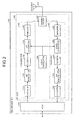
- Fig. 2 is a functional block diagram of the structure of a reader/writer 700.
- the reader/writer 700 is connected to a host computer and mediates a transaction of data between the host computer and the IC tag.
- the reader/writer 700 includes an RF unit 500 and a micro processing unit (MPU) 600 that generates a command that is transmitted to the IC tag, and analyzes a response that is received from the IC tag.
- the RF unit 500 includes a transmitter 100, a receiver 200, a local oscillator 300, and a coupling device 400 that uses an antenna 401 for transmitting and receiving the signals.
- the antenna 401 is connected to the RF unit 500.
- the transmitter 100 includes an encoder 101, an amplitude-modulation (AM) modulator 102, a filter 103, an up converter 104, and an amplifier 105.
- the encoder 101 encodes a command (including a read command and a write command) that is input from the MPU 600 by Manchester encoding.
- the AM modulator 102 determines strong and weak portions of amplitude of a carrier wave. By allotting "0" or "1" respectively to such differences of the amplitude, the AM modulator 102 carries out amplitude modulation of the command that is encoded by the encoder 101 such that the bit data can be transferred.
- the filter 103 selects a frequency of the carrier wave that is amplitude modulated by the AM modulator 102.
- the up converter 104 converts the frequency of the carrier wave that is selected by the filter 103 to a desired high frequency.
- the amplifier 105 amplifies a gain of the carrier wave that is converted to the high frequency by the up converter 104.
- the carrier wave that includes the amplified gain is transmitted from the antenna 401 via the shared device 400.
- the receiver 200 includes an amplifier 201, a down converter 202, a filter 203, an AM demodulator 204, and a decoder 205.
- the amplifier 201 amplifies a gain of a received carrier wave that is received from the antenna 401 via the shared device 400. Due to this, a weak received carrier wave is amplified.
- the down converter 202 converts the frequency of the carrier wave to a desired low frequency.
- the filter 203 selects the frequency of the carrier wave that is converted to the low frequency by the down converter 202.
- the AM demodulator 204 carries out amplitude demodulation and demodulates the analog signals from the bit data of the received wave.
- the decoder 205 decodes the data that is encoded by e.g. a FM0 encoding from baseband signals that are AM demodulated by the AM demodulator 204. An analog wave that is decoded by the decoder 205 is input into the MPU 600.
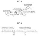
- Fig. 3 is a schematic for explaining the interference upon inclusion of the multiple reader/writers.
- an area r1 indicates a communication range of the reader/writer R/W 700a which will interfere the other reader/writers R/W 700b and the IC tag 800b.
- the area r1 includes an IC tag 800a.
- an area r2 indicates a communication range of the reader/writer R/W 700b which will interfere the other reader/writers R/W 700a and the IC tag 800a.
- the area r2 includes an IC tag 800b.
- the IC tag which is located in an area other than the area r1 that has the interference from the reader/writer R/W 700a. Due to this, the IC tag is not able to respond to a command from a reader/writer that is originally expected to communicate with the IC tag, thus resulting in the "interference between the reader/writer and the tag”. It is an objective of the present invention to eliminate the "interference between the reader/wrlter and the tag".
- Fig. 4 is a schematic for explaining a transmission duty and the carrier sensing. The transmission duty indicates the command transmission period from the reader/writer. The transmission duty is a process that selects the channel for the command transmission.
- the command transmission is terminated only during the minimum transmission termination period T 2 .
- the carrier sensing (CS) is carried out during the minimum transmission termination period T 2 .
- the reader/writer acquires the channel by the carrier sensing and again carries out the command transmission during the maximum continuous transmission period T 1 .
- the command transmission is terminated only during the minimum transmission termination period T 2 , and the CS is carried out.
- the reader/writer captures the channel using the carrier sensing and again carries out the command transmission during the maximum continuous transmission period T 1 .
- Fig. 5 is a flowchart of the carrier sensing process. As shown in Fig. 5, first the MPU 600 of the reader/writer 700 sets an initial channel (frequency) (step S101). Next, the MPU 600 measures received power of the received wave of the channel (step S102) and determines whether the received power of the received wave is less than or equal to a predetermined threshold value (for example, -74 dBm) (step S103).
- a predetermined threshold value for example, -74 dBm
- step S103 Upon the MPU 600 determining that the received power is less than or equal to the threshold value (step S103), the carrier sensing process moves to step S104. Upon the MPU 600 determining that the received power is larger than the threshold value (No at step S103), the carrier sensing process moves to step S109. Next, the MPU 600 randomly sets a back-off period that is a waiting period (step S104). The MPU 600 measures the received power during the back-off period that is set at step S104 (step S105).
- the MPU 600 determines whether the power measured during the back-off period is less than or equal to the threshold value (for example, -74 dBm) (step S106). Upon the MPU 600 determining that the received power is less than or equal to the threshold value (Yes at step S106), the carrier sensing process moves to step S107. Upon the MPU 600 determining that the received power is larger than the threshold value (No at step S106), the carrier sensing process moves to step S109.
- the threshold value for example, -74 dBm
- the MPU 600 transmits a command during a time period that is less than or equal to the maximum continuous transmission period T 1 .
- the MPU 600 terminates the command transmission during a time period that is more than or equal to the minimum transmission termination period T 2 (step S108).
- the carrier sensing process moves to step S101.
- the MPU 600 changes the channel (frequency) for the next carrier sensing at step S109. After a process of changing the channel is finished, the carrier sensing process moves to step S102.
- Fig. 6 is a functional block diagram of the structure of the MPU of the reader/writer according to an embodiment of the present invention.
- a structure of the reader/writer according to the embodiment other than the MPU is shown in Fig. 2.
- the MPU 600 includes a main controller 601, a transmitter 602, and a receiver 603.
- the main controller 601 controls the MPU 600.
- the main controller 601 includes a level measuring unit 601a, a nonresponse detecting unit 601b, an unused channel determining unit 601c, a channel setting unit 601d, a timeout period setting unit 601e, a transmission termination period setting unit 601f, a observation period setting unit 601g, and a transmission controller 601h.
- the level measuring unit 601a measures a level (output strength) of received signals (response signals) that are received from the IC tag, and outputs an individual measurement result to the unused channel determining unit 601c.
- the nonresponse detecting unit 601b detects a nonresponse from the IC tag during a timeout period.
- the nonresponse detecting unit 601b determines whether a ratio of a number of nonresponses of the IC tag during a timeout period exceeds a first predetermined value.
- the nonresponse detecting unit 601b also determines whether a ratio of a number of nonresponses of the IC tag during a second timeout period T check that is a fixed period at the end of the first timeout period exceeds a second predetermined value. Based on a determination result, upon determining that a timeout has occurred, the nonresponse detecting unit 601b adds 1 to a successive timeout count and outputs it to the timeout period setting unit 601e, the transmission termination period setting unit 601f, and the observation period setting unit 601g.
- the unused channel determining unit 601c searches for a channel of an unused frequency band and selects the channel.
- the channel setting unit 601d carries out a setting to allocate the channel selected by the unused channel determining unit 601c for the command transmission to the IC tag.
- Data of a set channel that is set by the channel setting unit 601d is output to the RF unit 500 for frequency setting.
- the timeout period setting unit 601e Based on the successive timeout count that is output by the nonresponse detecting unit 601b, the timeout period setting unit 601e sets the timeout period. If N to (number) is the successive timeout count, a timeout period T to (milliseconds) is calculated using the following expression. The timeout period setting unit 601e outputs the timeout period that is calculated by Equation (1) to the transmission controller 601h. [R] is a Gauss symbol and indicates a maximum integer that does not exceed a real number R.
- T to M to ⁇ ⁇ T + T init + T rnd
- M to [N to /T step ]
- N to is a successive timeout count
- T step is a constant
- ⁇ T is a constant that indicates an increment step value
- T init is a constant
- T rnd is a uniform random number such that 0 ⁇ T rnd ⁇ T rnd_max (where T rnd_max is a constant).
- T step Taking T step as “2”, ⁇ T as “10 to 20 milliseconds”, T init as “5 milliseconds”, and T rnd_max as “5 milliseconds” is desirable as an execution mode of Equation (1).
- the transmission termination period setting unit 601f sets a transmission termination period. If N to is the successive timeout count, a transmission termination period T sleep is calculated by the following expression.
- the timeout period setting unit 601e outputs the transmission termination period calculated by Equation (2) to the transmission controller 601h.
- T sleep T sleep_init / M to + 1 where M to is similar as Equation (1), and T sleep_init is a constant.
- the observation period setting unit 601g sets the observation period.
- the observation period T ct is calculated by Equation (3).
- the timeout period setting unit 601e outputs the observation period calculated by the following expression to the transmission controller 601h.
- T ct T sleep where T sleep is similar as in Equation (2).
- T rnd can be chosen according to a priority of the reader/writer, in other words, from a different range according to the successive timeout count N to .
- T rnd_max can differ according to the successive timeout count N to . If the different reader/writers having the same successive timeout count N to start the initial command transmission at the same timing, T to , T sleep , and T ct become the same, and the reader/writers semi permanently interfere with each other. However, due to different T rnd_max , occurrence of the aforementioned drawback can be reduced as much as possible.
- the transmission controller 601h Based on the timeout period T to set by the timeout period setting unit 601e, the transmission controller 601h detects a timeout according to a control command from an external device. The transmission controller 601h terminates the command transmission only during the transmission termination period T sleep that is set by the transmission termination period setting unit 601f. The transmission controller 601h outputs transmission control data of the command to the transmitter 602 to ensure that the timeout is repeatedly detected only during the observation period T ct that is set by the observation period setting unit 601g.
- the reader/writer After starting the command transmission by detecting the unused channel using the carrier sensing, upon detecting that communication with the IC tag cannot be carried out, the reader/writer assumes that interference has occurred with the IC tag and terminates the command transmission. Detection of the interference is explained below.
- the nonresponse detecting unit 601b evaluates whether the ratio of the number of nonresponses of the IC tag in response to the command from the reader/writer during the timeout period exceeds the first predetermined value. Based on the evaluation, if the ratio of the number of nonresponses of the IC tag is exceeding the first predetermined value, the nonresponse detecting unit 601b further calculates the ratio of the number of nonresponses of the IC tag during a second timeout period T check at the end of the timeout period T to for reconfirmation, and determines that the interference has been detected only if the ratio of the number of nonresponses of the IC tag exceeds the second predetermined value (the aforementioned process is called an interference detecting process).
- the reader/writer Upon detection of the interference, the reader/writer terminates the command transmission to the IC tag during the transmission termination period T sleep as a timeout process, and after lapse of the transmission termination period T sleep carries out the carrier sensing once again. If the interference is not detected, the interference detecting process is repeated from a start time of the command transmission during the observation period T ct . Because the interference detecting process is not carried out after the observation period T ct , the reader/writer that did not experienced the timeout during the observation period T ct can continue communication with the maximum continuous transmission period T 1 as the upper limit. However, if further communication is not necessary, the communication can also be ended before reaching the maximum continuous transmission period T 1 .
- the reader/writer Due to control based on Equation (1), because the timeout period T to of the reader/writer having a greater successive timeout count N to increases, the reader/writer is not easily timed out compared to other reader/writers having a lower value of the successive timeout count N to . Moreover, because the other reader/writers terminate the command transmission due to timeout, the reader/writer can increase a probability of getting a chance of the command transmission. Further, due to control based on Equations (2) and (3), the reader/writer having a greater successive timeout count N to increases a frequency of the carrier sensing and by limiting the observation period T ct reduces a possibility of getting timed out. Thus, the interference between the reader/writer and the IC tag can be autonomously avoided without the need to carry out complex settings each time a set up environment changes.
- the transmitter 602 exercises transmission control of a command that is transmitted from the host computer to the IC tag as the transmission data, and transmits the command to the RF unit 500.
- the receiver 603 distributes to the host computer as the received data, the received signals that are received from the IC tag via the RF unit 500.
- Fig. 7 is a flowchart of the carrier sensing process according to the embodiment. As shown in Fig. 7, first the channel setting unit 601d of the MPU 600 of the reader/writer 700 sets the initial channel (frequency) (step S201). Next, the level measuring unit 601a of the MPU 600 measures the received power of the received waves of the set channel (step S202) and determines whether the received power of the received waves is less than or equal to the threshold value (for example, -74 dBm) (step S203).
- the threshold value for example, -74 dBm
- the carrier sensing process moves to step S204.
- the carrier sensing process moves to step S208.
- the MPU 600 randomly sets the back-off period that is the waiting period (step S204).
- the level measuring unit 601a of the MPU 600 measures the received power during the back-off period that is set at step S204 (step S205).
- the level measuring unit 601a of the MPU 600 determines whether the measured power during the back-off period is less than or equal to the threshold value (for example, -74 dBm) (step S206). Upon determining that the received power is less than the threshold value (Yes at step S206), the carrier sensing process moves to step S207. Upon determining that the received power is not less than or equal to the threshold value (No at step S206), the carrier sensing process moves to step S208.
- the threshold value for example, -74 dBm
- the transmission controller 601h of the MPU 600 starts the command transmission.
- the non response detecting unit 601b of the MPU 600 determines whether the observation period T ct is yet to lapse, whether the ratio of the number of nonresponses of the IC tag during the timeout period T to is exceeding the first predetermined value, and whether the ratio of the number of nonresponses of the IC tag during the second timeout period T check is exceeding the second predetermined value (step S209).
- the carrier sensing process moves to step S210.
- the carrier sensing process moves to step S213.
- the nonresponse detecting unit 601b adds 1 to the timeout frequency N to .
- the MPU 600 sets the timeout period T to , the transmission termination period T sleep , and the observation period T ct (step S211).
- the MPU 600 terminates the command transmission during the transmission termination period T sleep (step S212).
- the carrier sensing process moves to step S201.
- the transmission controller 601h of the MPU 600 determines whether the maximum continuous transmission period T 1 has lapsed after starting the command transmission at step S207 (step S213). Upon the transmission controller 601h determining that the maximum continuous transmission period T 1 has lapsed (Yes at step S213), the carrier sensing process moves to step S214. Upon the transmission controller 601h determining that the maximum continuous transmission period T 1 has not lapsed (No at step S213), the carrier sensing process moves to step S209.
- the MPU 600 initializes the timeout period T to , the transmission termination period T sleep ,the observation period T ct , and the successive timeout count N to .
- the MPU 600 terminates the command transmission during a time period that is more than or equal to the minimum transmission termination period T 2 (step S215).
- the carrier sensing process moves to step S201.
- Fig. 8 is a schematic for explaining the operation during the timeout according to the embodiment.
- the reader/writer is timed out due to detection of interference in the first timeout period T to after carrying out the carrier sensing and starting the command transmission to the IC tag, and terminates the command transmission during the transmission termination period T sleep .
- the reader/writer starts the second command transmission by carrying out the carrier sensing immediately after lapse of the transmission termination period T sleep . Because the interference is not detected during the observation period T ct , the reader/writer communicates with the IC tag until the maximum continuous transmission period T 1 .
- Fig. 9 is a schematic for explaining the example of the operation (when three reader/writers are included) according to the embodiment.
- a first reader/wri ter includes an M to , of "1”
- a second reader/writer includes an M to of "0”
- a third reader/writer includes an M to of "0”.
- M to indicates a numerical value that increases according to the timeout frequency N to and is defined by Equation (1).
- the first reader/writer and the second reader/writer start the command transmission simultaneously, and are timed out together due to mutual interference. Because the third reader/writer starts the command transmission marginally later than the first reader/writer and the second reader/writer, the interference is not detected in the initial six interference detecting processes. Because the first reader/writer restarts the command transmission after the transmission termination period T sleep , the third reader/writer receives the interference and is timed out by the seventh interference detecting process.
- the second reader/writer restarts the command transmission after the transmission termination period T sleep , because the transmission termination period T sleep of the second reader/writer is greater than the transmission termination period T sleep of the first reader/writer, a time period that exceeds the observation period T ct lapses after the first reader/writer has already started the second command transmission, the second reader/writer detects the interference from the first reader/writer and is timed out again.
- the reader/writer having the greater successive timeout count N to can preferentially carry out the command transmission compared to the reader/writer having the smaller successive timeout count N to .
- each reader/writer uses a time-sharing operation that is based on autonomous control of each reader/writer to reduce the interference with the IC tag. Further, adaptive control of the reader/writers is also enabled such that the reader/writers automatically and autonomously adapt to the environment even if the set up environment changes.
- the constituent elements of the device illustrated are merely conceptual and may not necessarily physically resemble the structures shown in the drawings. For instance, the device need not necessarily have the structure that is illustrated.
- the device as a whole or in parts can be broken down or integrated either functionally or physically in accordance with the load or how the device is to be used.
- the process functions performed by the apparatus are entirely or partially realized by a program that is executed by a central processing unit (CPU) (or an MPU), a micro control unit (MCU) or by a hardware using wired logic.
- CPU central processing unit
- MCU micro control unit
- whether to terminate the signal transmission to the electronic tag during the fixed period is further determined during a fixed period at the end of a first predetermined period.
- the signal transmission of the RFID interrogator having a long first predetermined period can be carried out preferentially.
- whether the ratio of the number of nonresponses from the electronic tag during the first predetermined period has exceeded the predetermined value is repeatedly determined during a predetermined determination period.
- the signal transmission of the RFID interrogator having a short predetermined determination period can be carried out preferentially.
- the first predetermined period is decided according to a transmission termination frequency that causes the transmission to be terminated continuously during a second predetermined period.
- a possibility of the ratio of nonresponses from the electronic tag during the first predetermined period exceeding the predetermined value can be reduced in direct proportion to a continuous transmission termination frequency, and a preferential control of transmission termination according to the continuous transmission termination frequency is enabled.
- the second predetermined period is decided according to the continuous transmission termination frequency.
- the predetermined determination period is decided according to the continuous transmission termination frequency. Due to this, the predetermined determination period can be reduced in inverse proportion to the continuous transmission termination frequency. Thus, during the predetermined determination period, a number of determination results can be reduced in which the ratio of the number of nonresponses from the electronic tag during the first predetermined period has exceeded the predetermined value, and a preferential control of the transmission termination according to the continuous transmission termination frequency is enabled.
- the possibility of the ratio of nonresponses from the electronic tag during the first predetermined period exceeding the predetermined value can be reduced in direct proportion to the continuous transmission termination frequency.
- the preferential control of the transmission termination according to the continuous transmission termination frequency is enabled.
- the possibility of restarting the signal transmission to the electronic tag by quickly returning from the second predetermined period increases in direct proportion to the continuous transmission termination frequency.
- the preferential control of the transmission restart according to the continuous transmission termination frequency is enabled.
- the predetermined determination period can be reduced in direct proportion to the continuous transmission termination frequency. Due to this, during the predetermined determination period, the number of determination results can be reduced in which the ratio of the number of nonresponses from the electronic tag during the first predetermined period has exceeded the predetermined value. Thus, the preferential control of the transmission termination according to the continuous transmission termination frequency is enabled.
Landscapes
- Engineering & Computer Science (AREA)
- Physics & Mathematics (AREA)
- Toxicology (AREA)
- Health & Medical Sciences (AREA)
- Theoretical Computer Science (AREA)
- Artificial Intelligence (AREA)
- Computer Vision & Pattern Recognition (AREA)
- General Physics & Mathematics (AREA)
- General Health & Medical Sciences (AREA)
- Electromagnetism (AREA)
- Computer Networks & Wireless Communication (AREA)
- Near-Field Transmission Systems (AREA)
- Radar Systems Or Details Thereof (AREA)
Abstract
Description
- The present invention relates to a technology for performing a carrier sensing for selecting, upon stipulation of a maximum continuous transmission period for continuously transmitting signals to an electronic tag and a minimum transmission termination period for terminating the signal transmission after lapse of the maximum continuous transmission period, an appropriate frequency to be used in the signal transmission during the minimum transmission termination period before transmitting a signal to the electronic tag.
- Recently, a radio frequency identification (RFID) is one of the emphasized technologies in ubiquitous society. A system that uses the RFID includes interrogators such as reader/writers, readers etc., and responding devices such as electronic tags, wireless integrated-circuit (IC) tags, wireless tags, and RFID tags. For example, in a widely known RFID system, the reader/writers carry out product control by reading and writing data inside the electronic tags that are attached to products.
- The RFID system includes a plurality of reader/writers that are interfaces to communicate with the electronic tags. A correspondence is established between the electronic tags and the reader/writers. Each reader/writer communicates with the corresponding electronic tag, thereby enabling to read and write data in the electronic tag.
- If the reader/writers are communicating using radio waves of the same frequency, the reader/writers interfere with each other. For example, in a technology disclosed in European Telecommunications Standards Institute, "Electromagnetic compatibility and Radio spectrum Matters (ERM) ; Radio Frequency Identification Equipment operating in the band 865 MHz to 868 MHz with power levels up to 2W; Part 1: Technical requirements and methods of measurement", ETSI EN 302 208-1, V1.1.1, P. 9, 10, 26, each reader/writer carries out carrier sensing before starting communication and searches for an unused channel (frequency). Thus, by using the unused channels, the interference between the reader/writers can be avoided.
- A system, which carries out the carrier sensing, regulates a maximum continuous transmission period that enables to continuously transmit signals and a minimum transmission termination period that terminates signal transmission after lapse of the maximum continuous transmission period. Because a reader/writer that is awaiting signal transmission can get a chance to acquire a channel during a transmission termination period of the reader/writer in the signal transmission, the channels can be evenly used.
- However, in the conventional technology represented in the above literature, if the multiple reader/writers included proximally transmit signals simultaneously, the electronic tag receives the signals from the multiple reader/writers. Due to this, the electronic tag is not able to receive data correctly, thus resulting in interference between the reader/writers and the electronic tag. Because the electronic tag does not have frequency selectivity, even if each reader/writer carries out the carrier sensing and transmits the signals using different frequencies, the electronic tag responds to the signals from any of the reader/writers.
- To overcome the aforementioned drawback, for example, carrying out intensive control of a time-sharing operation is effective in preventing a time overlap during transmission of the reader/writers. However, because an extent of the interference from each reader/writer must be grasped beforehand to decide a control method, complex settings need to be carried out each time a set up environment changes.
- It is desirable to at least partially solve the problems in the conventional technology.
- A radio-frequency-identification interrogator according to an embodiment of one aspect of the present invention performs a communication-channel selecting process for selecting, upon stipulation of a maximum continuous transmission period to continuously transmit a signal to an electronic tag and a minimum transmission termination period to terminate a signal transmission after a lapse of the maximum continuous transmission period, an appropriate communication channel to be used in the signal transmission before the signal transmission to the electronic tag in the minimum transmission termination period. The radio-frequency-identification interrogator includes a nonresponse-ratio determining unit that determines, after starting the signal transmission, whether a ratio of number of nonresponses from the electronic tag exceeded a predetermined value in a first predetermined period; and a signal-transmission terminating unit that terminates, when it is determined that the ratio of the number of nonresponses from the electronic tag exceeded the predetermined value in the first predetermined period, the signal transmission to the electronic tag for a second predetermined period. The radio-frequency-identification interrogator performs, after a lapse of the second predetermined period, the communication-channel selecting process for restarting the signal transmission to the electronic tag.
- A method according to an embodiment of another aspect of the present invention is for controlling a radio-frequency-identification interrogator that performs a communication-channel selecting process for selecting, upon stipulation of a maximum continuous transmission period to continuously transmit a signal to an electronic tag and a minimum transmission termination period to terminate a signal transmission after a lapse of the maximum continuous transmission period, an appropriate communication channel to be used in the signal transmission before the signal transmission to the electronic tag in the minimum transmission termination period. The method includes determining, after starting the signal transmission, whether a ratio of number of nonresponses from the electronic tag exceeded a predetermined value in a first predetermined period; terminating, when it is determined that the ratio of the number of nonresponses from the electronic tag exceeded the predetermined value in the first predetermined period, the signal transmission to the electronic tag for a second predetermined period; and performing, after a lapse of the second predetermined period, the communication-channel selecting process for restarting the signal transmission to the electronic tag.
-
- Fig. 1 is a schematic for explaining a control of multiple reader/writers;
- Fig. 2 is a functional block diagram of a structure of a reader/writer;
- Fig. 3 is a schematic for explaining interference upon inclusion of the multiple reader/writers;
- Fig. 4 is a schematic for explaining a transmission duty and a carrier sensing;
- Fig. 5 is a flowchart of a sequence of a carrier sensing process;
- Fig. 6 is a functional block diagram of a structure of an MPU of the reader/writer according to an embodiment of the present invention;
- Fig. 7 is a flowchart of a sequence of a carrier sensing process according to the embodiment;
- Fig. 8 is a schematic for explaining an operation during a timeout according to the embodiment; and
- Fig. 9 is a schematic for explaining an example of an operation (when three reader/writers are included) according to the embodiment.
- Exemplary embodiments of the present invention are explained in detail below with reference to the accompanying drawings. According to the embodiments, an RFID interrogator is used as an IC tag reader/writer (hereinafter, "a reader/writer") and electronic tags that are used as RFID responding devices are embedded in a passive type IC having a maximum communication distance of approximately several meters.
- Figs. 1 to 5 are schematics for explaining a general reader/writer based on an RFID technology that is the prerequisite of the embodiments. Fig. 1 is a schematic for explaining a control of multiple reader/writers. Each of reader/writers R/W1 to R/W4 corresponds to multiple IC tags. The reader/writers R/W1 to R/W4 communicate with the corresponding multiple IC tags. A single controller intensively controls the reader/writers R/W1 to R/W4. Thus, the multiple reader/writers can communicate with stipulated target IC.
- Fig. 2 is a functional block diagram of the structure of a reader/
writer 700. The reader/writer 700 is connected to a host computer and mediates a transaction of data between the host computer and the IC tag. As shown in Fig. 2, the reader/writer 700 includes anRF unit 500 and a micro processing unit (MPU) 600 that generates a command that is transmitted to the IC tag, and analyzes a response that is received from the IC tag. TheRF unit 500 includes atransmitter 100, areceiver 200, alocal oscillator 300, and acoupling device 400 that uses an antenna 401 for transmitting and receiving the signals. The antenna 401 is connected to theRF unit 500. - The
transmitter 100 includes anencoder 101, an amplitude-modulation (AM)modulator 102, afilter 103, anup converter 104, and anamplifier 105. Theencoder 101 encodes a command (including a read command and a write command) that is input from the MPU 600 by Manchester encoding. For transmitting bit data by analog signals, theAM modulator 102 determines strong and weak portions of amplitude of a carrier wave. By allotting "0" or "1" respectively to such differences of the amplitude, theAM modulator 102 carries out amplitude modulation of the command that is encoded by theencoder 101 such that the bit data can be transferred. - The
filter 103 selects a frequency of the carrier wave that is amplitude modulated by theAM modulator 102. By synthesizing an oscillation output of a fixed or a variable frequency that is output by thelocal oscillator 300 for frequency conversion, the upconverter 104 converts the frequency of the carrier wave that is selected by thefilter 103 to a desired high frequency. Theamplifier 105 amplifies a gain of the carrier wave that is converted to the high frequency by the upconverter 104. The carrier wave that includes the amplified gain is transmitted from the antenna 401 via the shareddevice 400. - The
receiver 200 includes anamplifier 201, adown converter 202, afilter 203, anAM demodulator 204, and adecoder 205. Theamplifier 201 amplifies a gain of a received carrier wave that is received from the antenna 401 via the shareddevice 400. Due to this, a weak received carrier wave is amplified. By synthesizing the frequency of the carrier wave that is band limited by theamplifier 201 with the oscillation output of the fixed or the variable frequency that is output by thelocal oscillator 300, thedown converter 202 converts the frequency of the carrier wave to a desired low frequency. - The
filter 203 selects the frequency of the carrier wave that is converted to the low frequency by thedown converter 202. The AM demodulator 204 carries out amplitude demodulation and demodulates the analog signals from the bit data of the received wave. Thedecoder 205 decodes the data that is encoded by e.g. a FM0 encoding from baseband signals that are AM demodulated by theAM demodulator 204. An analog wave that is decoded by thedecoder 205 is input into theMPU 600. - Fig. 3 is a schematic for explaining the interference upon inclusion of the multiple reader/writers. As shown in Fig. 3, an area r1 indicates a communication range of the reader/writer R/
W 700a which will interfere the other reader/writers R/W 700b and theIC tag 800b. The area r1 includes anIC tag 800a. Further, an area r2 indicates a communication range of the reader/writer R/W 700b which will interfere the other reader/writers R/W 700a and theIC tag 800a. The area r2 includes anIC tag 800b. - Dense deployment of the multiple reader/writers results in the occurrence of "interference between the reader/writers" and "interference between the reader/writer and the tag". Because the interfering reader/writer R/
W 700a and the victim reader/writer R/W 700b communicate with the IC tag using the same frequency, communication signals cannot be identified, thus resulting in the "interference between the reader/writers". However, in the conventional technology, using a different channel (frequency) for each reader/writer to communicate with the IC tag enables to overcome the interference between the reader/writers, as is explained later. - The IC tag which is located in an area other than the area r1 that has the interference from the reader/writer R/
W 700a. Due to this, the IC tag is not able to respond to a command from a reader/writer that is originally expected to communicate with the IC tag, thus resulting in the "interference between the reader/writer and the tag". It is an objective of the present invention to eliminate the "interference between the reader/wrlter and the tag". - The conventional technology includes a limit on a maximum value of a command transmission period from the reader/writer (a maximum continuous transmission period T1:T1=4 seconds). Further, for carrying out a carrier sensing after lapse of the maximum value of the command transmission period, a minimum transmission termination period T2 (T2=50 milliseconds or 100 milliseconds) is included that terminates the command transmission. Due to this, the other reader/writers can carry out a carrier sensing by interrupting and start transmission using another channel. Fig. 4 is a schematic for explaining a transmission duty and the carrier sensing. The transmission duty indicates the command transmission period from the reader/writer. The transmission duty is a process that selects the channel for the command transmission.
- As shown in Fig. 4, after the command transmission during the maximum continuous transmission period T1 is finished, the command transmission is terminated only during the minimum transmission termination period T2. The carrier sensing (CS) is carried out during the minimum transmission termination period T2. The reader/writer acquires the channel by the carrier sensing and again carries out the command transmission during the maximum continuous transmission period T1. After the command transmission during the maximum continuous transmission period T1 is finished, the command transmission is terminated only during the minimum transmission termination period T2, and the CS is carried out. The reader/writer captures the channel using the carrier sensing and again carries out the command transmission during the maximum continuous transmission period T1.
- Fig. 5 is a flowchart of the carrier sensing process. As shown in Fig. 5, first the
MPU 600 of the reader/writer 700 sets an initial channel (frequency) (step S101). Next, theMPU 600 measures received power of the received wave of the channel (step S102) and determines whether the received power of the received wave is less than or equal to a predetermined threshold value (for example, -74 dBm) (step S103). - Upon the
MPU 600 determining that the received power is less than or equal to the threshold value (step S103), the carrier sensing process moves to step S104. Upon theMPU 600 determining that the received power is larger than the threshold value (No at step S103), the carrier sensing process moves to step S109. Next, theMPU 600 randomly sets a back-off period that is a waiting period (step S104). TheMPU 600 measures the received power during the back-off period that is set at step S104 (step S105). - The
MPU 600 determines whether the power measured during the back-off period is less than or equal to the threshold value (for example, -74 dBm) (step S106). Upon theMPU 600 determining that the received power is less than or equal to the threshold value (Yes at step S106), the carrier sensing process moves to step S107. Upon theMPU 600 determining that the received power is larger than the threshold value (No at step S106), the carrier sensing process moves to step S109. - At step S107, the
MPU 600 transmits a command during a time period that is less than or equal to the maximum continuous transmission period T1. TheMPU 600 terminates the command transmission during a time period that is more than or equal to the minimum transmission termination period T2 (step S108). After a process of terminating the command transmission is finished, the carrier sensing process moves to step S101. TheMPU 600 changes the channel (frequency) for the next carrier sensing at step S109. After a process of changing the channel is finished, the carrier sensing process moves to step S102. - Fig. 6 is a functional block diagram of the structure of the MPU of the reader/writer according to an embodiment of the present invention. A structure of the reader/writer according to the embodiment other than the MPU is shown in Fig. 2.
- The
MPU 600 includes amain controller 601, atransmitter 602, and areceiver 603. Themain controller 601 controls theMPU 600. Themain controller 601 includes alevel measuring unit 601a, anonresponse detecting unit 601b, an unusedchannel determining unit 601c, achannel setting unit 601d, a timeoutperiod setting unit 601e, a transmission terminationperiod setting unit 601f, a observationperiod setting unit 601g, and atransmission controller 601h. - The
level measuring unit 601a measures a level (output strength) of received signals (response signals) that are received from the IC tag, and outputs an individual measurement result to the unusedchannel determining unit 601c. Thenonresponse detecting unit 601b detects a nonresponse from the IC tag during a timeout period. Thenonresponse detecting unit 601b determines whether a ratio of a number of nonresponses of the IC tag during a timeout period exceeds a first predetermined value. Thenonresponse detecting unit 601b also determines whether a ratio of a number of nonresponses of the IC tag during a second timeout period Tcheck that is a fixed period at the end of the first timeout period exceeds a second predetermined value. Based on a determination result, upon determining that a timeout has occurred, thenonresponse detecting unit 601b adds 1 to a successive timeout count and outputs it to the timeoutperiod setting unit 601e, the transmission terminationperiod setting unit 601f, and the observationperiod setting unit 601g. - The unused
channel determining unit 601c searches for a channel of an unused frequency band and selects the channel. Thechannel setting unit 601d carries out a setting to allocate the channel selected by the unusedchannel determining unit 601c for the command transmission to the IC tag. Data of a set channel that is set by thechannel setting unit 601d is output to theRF unit 500 for frequency setting. - Based on the successive timeout count that is output by the
nonresponse detecting unit 601b, the timeoutperiod setting unit 601e sets the timeout period. If Nto (number) is the successive timeout count, a timeout period Tto (milliseconds) is calculated using the following expression. The timeoutperiod setting unit 601e outputs the timeout period that is calculated by Equation (1) to thetransmission controller 601h. [R] is a Gauss symbol and indicates a maximum integer that does not exceed a real number R.
where Mto=[Nto/Tstep], Nto is a successive timeout count, Tstep is a constant, ΔT is a constant that indicates an increment step value, Tinit is a constant, and Trnd is a uniform random number such that 0≤Trnd≤Trnd_max (where Trnd_max is a constant). - If different reader/writers start an initial command transmission at the same timing, the successive timeout count Nto becomes the same. Subsequently, Tto, Tsleep, and Tct become the same, and the reader/writers semi-permanently interfere with each other. However, if a uniform random number Trnd (milliseconds) is added to Tto, occurrence of the aforementioned drawback can be reduced as much as possible.
- Taking Tstep as "2", ΔT as "10 to 20 milliseconds", Tinit as "5 milliseconds", and Trnd_max as "5 milliseconds" is desirable as an execution mode of Equation (1).
- Based on the successive timeout count that is output by the
nonresponse detecting unit 601b, the transmission terminationperiod setting unit 601f sets a transmission termination period. If Nto is the successive timeout count, a transmission termination period Tsleep is calculated by the following expression. The timeoutperiod setting unit 601e outputs the transmission termination period calculated by Equation (2) to thetransmission controller 601h.
where Mto is similar as Equation (1), and Tsleep_init is a constant. - Taking Tsleep_init as "4 seconds" is desirable as an execution mode of Equation (2).
- Based on the successive timeout count that is output by the
nonresponse detecting unit 601b, the observationperiod setting unit 601g sets the observation period. The observation period Tct is calculated by Equation (3). The timeoutperiod setting unit 601e outputs the observation period calculated by the following expression to thetransmission controller 601h.
where Tsleep is similar as in Equation (2). - Trnd can be chosen according to a priority of the reader/writer, in other words, from a different range according to the successive timeout count Nto. In other words, Trnd_max can differ according to the successive timeout count Nto. If the different reader/writers having the same successive timeout count Nto start the initial command transmission at the same timing, Tto, Tsleep, and Tct become the same, and the reader/writers semi permanently interfere with each other. However, due to different Trnd_max, occurrence of the aforementioned drawback can be reduced as much as possible.
- Based on the timeout period Tto set by the timeout
period setting unit 601e, thetransmission controller 601h detects a timeout according to a control command from an external device. Thetransmission controller 601h terminates the command transmission only during the transmission termination period Tsleep that is set by the transmission terminationperiod setting unit 601f. Thetransmission controller 601h outputs transmission control data of the command to thetransmitter 602 to ensure that the timeout is repeatedly detected only during the observation period Tct that is set by the observationperiod setting unit 601g. - After starting the command transmission by detecting the unused channel using the carrier sensing, upon detecting that communication with the IC tag cannot be carried out, the reader/writer assumes that interference has occurred with the IC tag and terminates the command transmission. Detection of the interference is explained below.
- The
nonresponse detecting unit 601b evaluates whether the ratio of the number of nonresponses of the IC tag in response to the command from the reader/writer during the timeout period exceeds the first predetermined value. Based on the evaluation, if the ratio of the number of nonresponses of the IC tag is exceeding the first predetermined value, thenonresponse detecting unit 601b further calculates the ratio of the number of nonresponses of the IC tag during a second timeout period Tcheck at the end of the timeout period Tto for reconfirmation, and determines that the interference has been detected only if the ratio of the number of nonresponses of the IC tag exceeds the second predetermined value (the aforementioned process is called an interference detecting process). - Upon detection of the interference, the reader/writer terminates the command transmission to the IC tag during the transmission termination period Tsleep as a timeout process, and after lapse of the transmission termination period Tsleep carries out the carrier sensing once again. If the interference is not detected, the interference detecting process is repeated from a start time of the command transmission during the observation period Tct. Because the interference detecting process is not carried out after the observation period Tct, the reader/writer that did not experienced the timeout during the observation period Tct can continue communication with the maximum continuous transmission period T1 as the upper limit. However, if further communication is not necessary, the communication can also be ended before reaching the maximum continuous transmission period T1.
- Due to control based on Equation (1), because the timeout period Tto of the reader/writer having a greater successive timeout count Nto increases, the reader/writer is not easily timed out compared to other reader/writers having a lower value of the successive timeout count Nto. Moreover, because the other reader/writers terminate the command transmission due to timeout, the reader/writer can increase a probability of getting a chance of the command transmission. Further, due to control based on Equations (2) and (3), the reader/writer having a greater successive timeout count Nto increases a frequency of the carrier sensing and by limiting the observation period Tct reduces a possibility of getting timed out. Thus, the interference between the reader/writer and the IC tag can be autonomously avoided without the need to carry out complex settings each time a set up environment changes.
- Based on the transmission control data from the
transmission controller 601h, thetransmitter 602 exercises transmission control of a command that is transmitted from the host computer to the IC tag as the transmission data, and transmits the command to theRF unit 500. Thereceiver 603 distributes to the host computer as the received data, the received signals that are received from the IC tag via theRF unit 500. - Fig. 7 is a flowchart of the carrier sensing process according to the embodiment. As shown in Fig. 7, first the
channel setting unit 601d of theMPU 600 of the reader/writer 700 sets the initial channel (frequency) (step S201). Next, thelevel measuring unit 601a of theMPU 600 measures the received power of the received waves of the set channel (step S202) and determines whether the received power of the received waves is less than or equal to the threshold value (for example, -74 dBm) (step S203). - Upon determining that the received power is less than or equal to the threshold value (Yes at step S203), the carrier sensing process moves to step S204. Upon determining that the received power is not less than or equal to the threshold value (No at step S203), the carrier sensing process moves to step S208. Next, the
MPU 600 randomly sets the back-off period that is the waiting period (step S204). Next, thelevel measuring unit 601a of theMPU 600 measures the received power during the back-off period that is set at step S204 (step S205). - The
level measuring unit 601a of theMPU 600 determines whether the measured power during the back-off period is less than or equal to the threshold value (for example, -74 dBm) (step S206). Upon determining that the received power is less than the threshold value (Yes at step S206), the carrier sensing process moves to step S207. Upon determining that the received power is not less than or equal to the threshold value (No at step S206), the carrier sensing process moves to step S208. - At step S207, the
transmission controller 601h of theMPU 600 starts the command transmission. The nonresponse detecting unit 601b of theMPU 600 determines whether the observation period Tct is yet to lapse, whether the ratio of the number of nonresponses of the IC tag during the timeout period Tto is exceeding the first predetermined value, and whether the ratio of the number of nonresponses of the IC tag during the second timeout period Tcheck is exceeding the second predetermined value (step S209). - Upon the
nonresponse detecting unit 601b determining that the observation period Tct is yet to lapse, the ratio of the number of nonresponses of the IC tag during the timeout period Tto is exceeding the first predetermined value, and the ratio of the number of nonresponses of the IC tag during the second timeout period Tcheck is exceeding the second predetermined value (Yes at step S209), the carrier sensing process moves to step S210. Upon thenonresponse detecting unit 601b determining that the observation period Tct has lapsed, the ratio of the number of nonresponses of the IC tag during the timeout period Tto is less than or equal to the first predetermined value, or the ratio of the number of nonresponses of the IC tag during the second timeout period Tcheck is less than or equal to the second predetermined value (No at step S209), the carrier sensing process moves to step S213. - At step S210, the
nonresponse detecting unit 601b adds 1 to the timeout frequency Nto. Based on Equations (1) to (3), theMPU 600 sets the timeout period Tto, the transmission termination period Tsleep, and the observation period Tct (step S211). Next, theMPU 600 terminates the command transmission during the transmission termination period Tsleep (step S212). Upon completion of a process to terminate the command transmission, the carrier sensing process moves to step S201. - At step S213, the
transmission controller 601h of theMPU 600 determines whether the maximum continuous transmission period T1 has lapsed after starting the command transmission at step S207 (step S213). Upon thetransmission controller 601h determining that the maximum continuous transmission period T1 has lapsed (Yes at step S213), the carrier sensing process moves to step S214. Upon thetransmission controller 601h determining that the maximum continuous transmission period T1 has not lapsed (No at step S213), the carrier sensing process moves to step S209. - At step S214, the
MPU 600 initializes the timeout period Tto, the transmission termination period Tsleep,the observation period Tct, and the successive timeout count Nto. Next, theMPU 600 terminates the command transmission during a time period that is more than or equal to the minimum transmission termination period T2 (step S215). Upon completion of a process to terminate the command transmission, the carrier sensing process moves to step S201. - An operation during the timeout according to the embodiment is explained next. Fig. 8 is a schematic for explaining the operation during the timeout according to the embodiment. As shown in Fig. 8, the reader/writer is timed out due to detection of interference in the first timeout period Tto after carrying out the carrier sensing and starting the command transmission to the IC tag, and terminates the command transmission during the transmission termination period Tsleep. The reader/writer starts the second command transmission by carrying out the carrier sensing immediately after lapse of the transmission termination period Tsleep. Because the interference is not detected during the observation period Tct, the reader/writer communicates with the IC tag until the maximum continuous transmission period T1.
- Fig. 9 is a schematic for explaining the example of the operation (when three reader/writers are included) according to the embodiment. As shown in Fig. 9, a first reader/wri ter includes an Mto, of "1", a second reader/writer includes an Mto of "0", and a third reader/writer includes an Mto of "0". Mto indicates a numerical value that increases according to the timeout frequency Nto and is defined by Equation (1).
- The first reader/writer and the second reader/writer start the command transmission simultaneously, and are timed out together due to mutual interference. Because the third reader/writer starts the command transmission marginally later than the first reader/writer and the second reader/writer, the interference is not detected in the initial six interference detecting processes. Because the first reader/writer restarts the command transmission after the transmission termination period Tsleep, the third reader/writer receives the interference and is timed out by the seventh interference detecting process.
- Although the second reader/writer restarts the command transmission after the transmission termination period Tsleep, because the transmission termination period Tsleep of the second reader/writer is greater than the transmission termination period Tsleep of the first reader/writer, a time period that exceeds the observation period Tct lapses after the first reader/writer has already started the second command transmission, the second reader/writer detects the interference from the first reader/writer and is timed out again. Thus, the reader/writer having the greater successive timeout count Nto can preferentially carry out the command transmission compared to the reader/writer having the smaller successive timeout count Nto.
- According to the embodiment, without linking to the other reader/writers using a wired network, each reader/writer uses a time-sharing operation that is based on autonomous control of each reader/writer to reduce the interference with the IC tag. Further, adaptive control of the reader/writers is also enabled such that the reader/writers automatically and autonomously adapt to the environment even if the set up environment changes.
- All the processes explained in the embodiment can be realized by executing a prior formulated program by a computer system such as a personal computer, a server, or a workstation.
- The invention in its broader aspects is not limited to the specific details and representative embodiments shown and described herein. Accordingly, various modifications may be made without departing from the spirit or scope of the general inventive concept as defined by the appended claims and their equivalents. Further, effects described in the embodiments are not to be thus limited.
- All the automatic processes explained in the present embodiment can be, entirely or in part, carried out manually. Similarly, all the manual processes explained in the present embodiment can be entirely or in part carried out automatically by a known method.
- The sequence of processes, the sequence of controls, specific names, and data including every type of data or various parameters can be changed as required unless otherwise specified.
- The constituent elements of the device illustrated are merely conceptual and may not necessarily physically resemble the structures shown in the drawings. For instance, the device need not necessarily have the structure that is illustrated. The device as a whole or in parts can be broken down or integrated either functionally or physically in accordance with the load or how the device is to be used.
- The process functions performed by the apparatus are entirely or partially realized by a program that is executed by a central processing unit (CPU) (or an MPU), a micro control unit (MCU) or by a hardware using wired logic.
- As describe above, according to an embodiment of the present invention, if a ratio of nonresponses from an electronic tag during a first predetermined period has exceeded a predetermined value, signal transmission is terminated during a fixed period. Thus, interference between a plurality of RFID interrogators and the electronic tag can be curbed.
- Furthermore, according to an embodiment of the present invention, whether to terminate the signal transmission to the electronic tag during the fixed period is further determined during a fixed period at the end of a first predetermined period. Thus, the signal transmission of the RFID interrogator having a long first predetermined period can be carried out preferentially.
- Moreover, according to an embodiment of the present invention, whether the ratio of the number of nonresponses from the electronic tag during the first predetermined period has exceeded the predetermined value is repeatedly determined during a predetermined determination period. Thus, the signal transmission of the RFID interrogator having a short predetermined determination period can be carried out preferentially.
- Furthermore, according to an embodiment of the present invention, the first predetermined period is decided according to a transmission termination frequency that causes the transmission to be terminated continuously during a second predetermined period. Thus, a possibility of the ratio of nonresponses from the electronic tag during the first predetermined period exceeding the predetermined value can be reduced in direct proportion to a continuous transmission termination frequency, and a preferential control of transmission termination according to the continuous transmission termination frequency is enabled.
- Moreover, according to an embodiment of the present invention, the second predetermined period is decided according to the continuous transmission termination frequency. Thus, a possibility of restarting the signal transmission to the electronic tag by quickly returning from the second predetermined period increases in direct proportion to the continuous transmission termination frequency, and a preferential control of transmission restart according to the continuous transmission termination frequency is enabled.
- Furthermore, according to an embodiment of the present invention, the predetermined determination period is decided according to the continuous transmission termination frequency. Due to this, the predetermined determination period can be reduced in inverse proportion to the continuous transmission termination frequency. Thus, during the predetermined determination period, a number of determination results can be reduced in which the ratio of the number of nonresponses from the electronic tag during the first predetermined period has exceeded the predetermined value, and a preferential control of the transmission termination according to the continuous transmission termination frequency is enabled.
- Moreover, according to an embodiment of the present invention, the possibility of the ratio of nonresponses from the electronic tag during the first predetermined period exceeding the predetermined value can be reduced in direct proportion to the continuous transmission termination frequency. Thus, the preferential control of the transmission termination according to the continuous transmission termination frequency is enabled.
- Furthermore, according to an embodiment of the present invention, the possibility of restarting the signal transmission to the electronic tag by quickly returning from the second predetermined period increases in direct proportion to the continuous transmission termination frequency. Thus, the preferential control of the transmission restart according to the continuous transmission termination frequency is enabled.
- Moreover, according to an embodiment of the present invention, the predetermined determination period can be reduced in direct proportion to the continuous transmission termination frequency. Due to this, during the predetermined determination period, the number of determination results can be reduced in which the ratio of the number of nonresponses from the electronic tag during the first predetermined period has exceeded the predetermined value. Thus, the preferential control of the transmission termination according to the continuous transmission termination frequency is enabled.
- Although the invention has been described with respect to a specific embodiment for a complete and clear disclosure, the appended claims are not to be thus limited but are to be construed as embodying all modifications and alternative constructions that may occur to one skilled in the art that fairly fall within the basic teaching herein set forth.
Claims (20)
- A radio-frequency-identification interrogator that performs a communication-channel selecting process for selecting, upon stipulation of a maximum continuous transmission period to continuously transmit a signal to an electronic tag and a minimum transmission termination period to terminate a signal transmission after a lapse of the maximum continuous transmission period, an appropriate communication channel to be used in the signal transmission before the signal transmission to the electronic tag in the minimum transmission termination period, the radio-frequency-identification interrogator comprising:a nonresponse-ratio determining unit that determines, after starting the signal transmission, whether a ratio of number of nonresponses from the electronic tag exceeded a predetermined value in a first predetermined period; anda signal-transmission terminating unit that terminates, when it is determined that the ratio of the number of nonresponses from the electronic tag exceeded the predetermined value in the first predetermined period, the signal transmission to the electronic tag for a second predetermined period, whereinthe radio-frequency-identification interrogator performs, after a lapse of the second predetermined period, the communication-channel selecting process for restarting the signal transmission to the electronic tag.
- The radio-frequency-identification interrogator according to claim 1, wherein
the nonresponse-ratio determining unit further determines, when it is determined that the ratio of the number of nonresponses from the electronic tag exceeded the predetermined value in the first predetermined period, whether the ratio of the number of nonresponses exceeded the predetermined value during a fixed period at the end of the first predetermined period, and
the signal-transmission terminating unit terminates, when it is determined that the ratio of the number of nonresponses from the electronic tag exceeded the predetermined value in the fixed period, the signal transmission to the electronic tag for the second predetermined period. - The radio-frequency-identification interrogator according to claim 1, wherein
the nonresponse-ratio determining unit repeats determination whether the ratio of the number of nonresponses from the electronic tag exceeded the predetermined value in the first predetermined period, during a predetermined determination period. - The radio-frequency-identification interrogator according to claim 3, further comprising:a transmission-termination counting unit that counts a successive transmission termination count that is continued upon the signal-transmission terminating unit terminating the signal transmission to the electronic tag during the second predetermined period; anda first predetermined-period deciding unit that decides the first predetermined period based on the successive transmission termination count.
- The radio-frequency-identification interrogator according to claim 4, further comprising:a second predetermined-period deciding unit that decides the second predetermined period based on the successive transmission termination count.
- The radio-frequency-identification interrogator according to claim 4, further comprising:a predetermined-determination-period deciding unit that decides the predetermined determination period based on the successive transmission termination count.
- The radio-frequency-identification interrogator according to claim 4, wherein
the first predetermined-period deciding unit decides the first predetermined period in direct proportion to the successive transmission termination count. - The radio-frequency-identification interrogator according to claim 5, wherein
the second predetermined-period deciding unit decides the second predetermined period in inverse proportion to the successive transmission termination count. - The radio-frequency-identification interrogator according to claim 6, wherein
the predetermined-determination-period deciding unit decides the predetermined determination period in inverse proportion to the successive transmission termination count. - The radio-frequency-identification interrogator according to claim 7, wherein
the first predetermined-period deciding unit decides the first predetermined period by
where Tto is the first predetermined period, Mto=[Nto/Tstep], Nto is a successive transmission termination count, Tstep is a constant, ΔT is a constant indicating an increment step value, Tinit is a constant, and Trnd is a uniform random number such that 0≤Trnd≤Trnd_max (where Trnd_max is a constant). - The radio-frequency-identification interrogator according to claim 10, wherein
the uniform random number is selected from a different range according to a priority of the signal transmission based on the successive signal termination count. - The radio-frequency-identification interrogator according to claim 8, wherein
the second predetermined-period deciding unit decides the second predetermined period by
where Tsleep is the second predetermined period, Mto=[Nto/Tstep], Nto is a successive transmission termination count, Tstep is a constant, and Tsleep_init is a constant. - The radio-frequency-identification interrogator according to claim 9, wherein
the predetermined-determination-period deciding unit decides the predetermined determination period by
where Tct is the predetermined determination period, Tsleep=Tsleep_init/(Mto+1), Tsleep is the second predetermined period, Mto=[Nto/Tstep] , Nto is a successive transmission termination count, Tstep is a constant, and Tsleep_init is a constant. - The radio-frequency-identification interrogator according to claim 6, further comprising:an initializing unit that initializes, when the nonresponse-ratio determining unit repeatedly determines whether the ratio of the number of nonresponses from the electronic tag exceeded the predetermined value in the first predetermined period during the predetermined determination period, and when it is determined that the ratio of the number of nonresponses from the electronic tag did not exceed the predetermined value in the first predetermined period in all determinations, the first predetermined period, the second predetermined period, and the predetermined determination period.
- A method of controlling a radio-frequency-identification interrogator that performs a communication-channel selecting process for selecting, upon stipulation of a maximum continuous transmission period to continuously transmit a signal to an electronic tag and a minimum transmission termination period to terminate a signal transmission after a lapse of the maximum continuous transmission period, an appropriate communication channel to be used in the signal transmission before the signal transmission to the electronic tag in the minimum transmission termination period, the method comprising:determining, after starting the signal transmission, whether a ratio of number of nonresponses from the electronic tag exceeded a predetermined value in a first predetermined period;terminating, when it is determined that the ratio of the number of nonresponses from the electronic tag exceeded the predetermined value in the first predetermined period, the signal transmission to the electronic tag for a second predetermined period; andperforming, after a lapse of the second predetermined period, the communication-channel selecting process for restarting the signal transmission to the electronic tag.
- The method according to claim 15, wherein
the determining includes determining, when it is determined that the ratio of the number of nonresponses from the electronic tag exceeded the predetermined value in the first predetermined period, whether the ratio of the number of nonresponses exceeded the predetermined value during a fixed period at the end of the first predetermined period, and
the terminating includes terminating, when it is determined that the ratio of the number of nonresponses from the electronic tag exceeded the predetermined value in the fixed period, the signal transmission to the electronic tag for the second predetermined period. - The method according to claim 15, wherein
the determining includes repeating determination whether the ratio of the number of nonresponses from the electronic tag exceeded the predetermined value in the first predetermined period, during a predetermined determination period. - The method according to claim 17, further comprising:counting a successive transmission termination count that is continued when the signal transmission to the electronic tag is terminated during the second predetermined period; anddeciding the first predetermined period based on the successive transmission termination count.
- The method according to claim 18, further comprising:deciding the second predetermined period based on the successive transmission termination count.
- The method according to claim 18, further comprising:deciding the predetermined determination period based on the successive transmission termination count.
Applications Claiming Priority (1)
| Application Number | Priority Date | Filing Date | Title |
|---|---|---|---|
| JP2006249832A JP4762093B2 (en) | 2006-09-14 | 2006-09-14 | RFID interrogator and RFID interrogator control method |
Publications (2)
| Publication Number | Publication Date |
|---|---|
| EP1901200A2 true EP1901200A2 (en) | 2008-03-19 |
| EP1901200A3 EP1901200A3 (en) | 2009-04-29 |
Family
ID=38787706
Family Applications (1)
| Application Number | Title | Priority Date | Filing Date |
|---|---|---|---|
| EP07106983A Withdrawn EP1901200A3 (en) | 2006-09-14 | 2007-04-26 | RFID interrogator and RFID-interrogator control method |
Country Status (3)
| Country | Link |
|---|---|
| US (1) | US7902982B2 (en) |
| EP (1) | EP1901200A3 (en) |
| JP (1) | JP4762093B2 (en) |
Families Citing this family (9)
| Publication number | Priority date | Publication date | Assignee | Title |
|---|---|---|---|---|
| US20070257775A1 (en) * | 2006-04-28 | 2007-11-08 | Tatsuji Nishijima | Identification system and identification method |
| JP2008270978A (en) * | 2007-04-17 | 2008-11-06 | Toshiba Tec Corp | Wireless communication device |
| KR101478144B1 (en) * | 2007-12-27 | 2015-01-02 | 삼성전자주식회사 | Rfid communication method |
| JP5376886B2 (en) * | 2008-09-30 | 2013-12-25 | 沖電気工業株式会社 | Wireless transmission apparatus, program, and method |
| KR20110126481A (en) * | 2010-05-17 | 2011-11-23 | 엘에스산전 주식회사 | RFID Reader |
| US8594121B2 (en) * | 2011-04-20 | 2013-11-26 | Qualcomm Incorporated | Cognitive radio spectrum sensor employing peak-to-average ratio as the signal feature |
| WO2012149869A1 (en) * | 2011-05-03 | 2012-11-08 | 国民技术股份有限公司 | Communication method, communication device and communication system |
| US9667303B2 (en) * | 2015-01-28 | 2017-05-30 | Lam Research Corporation | Dual push between a host computer system and an RF generator |
| CN116762426A (en) * | 2021-01-29 | 2023-09-15 | 华为技术有限公司 | Label positioning method and device |
Family Cites Families (12)
| Publication number | Priority date | Publication date | Assignee | Title |
|---|---|---|---|---|
| US5640151A (en) * | 1990-06-15 | 1997-06-17 | Texas Instruments Incorporated | Communication system for communicating with tags |
| JPH10293824A (en) * | 1997-04-18 | 1998-11-04 | Omron Corp | Identification system and data reader |
| US6393457B1 (en) * | 1998-07-13 | 2002-05-21 | International Business Machines Corporation | Architecture and apparatus for implementing 100 Mbps and GBPS Ethernet adapters |
| US6917291B2 (en) * | 1998-10-26 | 2005-07-12 | Identec Solutions Inc. | Interrogation, monitoring and data exchange using RFID tags |
| US6643278B1 (en) * | 1999-03-23 | 2003-11-04 | Texas Instruments Incorporated | Wireless network circuits, systems, and methods for frequency hopping with reduced packet interference |
| US20020045956A1 (en) * | 2000-02-18 | 2002-04-18 | Kapitan Brian A. | Network distributed motion control system |
| US7253717B2 (en) * | 2000-11-29 | 2007-08-07 | Mobile Technics Llc | Method and system for communicating with and tracking RFID transponders |
| US6975206B2 (en) * | 2002-08-30 | 2005-12-13 | Intellectual Property, Llc | Method for communication between central terminal and multiple transponders |
| TWI290303B (en) * | 2003-06-20 | 2007-11-21 | Sunplus Technology Co Ltd | RFID communication system and search method thereof |
| US7817612B2 (en) * | 2003-07-29 | 2010-10-19 | Sony Corporation | Decentralized wireless communication system, apparatus, and associated methodology |
| JP4394007B2 (en) * | 2005-01-13 | 2010-01-06 | 三菱電機株式会社 | Reader / writer device |
| US20070075838A1 (en) * | 2005-10-04 | 2007-04-05 | Symbol Technologies, Inc. | Method and apparatus for avoiding radio frequency identification (RFID) tag response collisions |
-
2006
- 2006-09-14 JP JP2006249832A patent/JP4762093B2/en not_active Expired - Fee Related
-
2007
- 2007-04-26 EP EP07106983A patent/EP1901200A3/en not_active Withdrawn
- 2007-04-27 US US11/790,790 patent/US7902982B2/en not_active Expired - Fee Related
Non-Patent Citations (1)
| Title |
|---|
| No Search * |
Also Published As
| Publication number | Publication date |
|---|---|
| JP2008072508A (en) | 2008-03-27 |
| JP4762093B2 (en) | 2011-08-31 |
| EP1901200A3 (en) | 2009-04-29 |
| US7902982B2 (en) | 2011-03-08 |
| US20080068168A1 (en) | 2008-03-20 |
Similar Documents
| Publication | Publication Date | Title |
|---|---|---|
| EP1901200A2 (en) | RFID interrogator and RFID-interrogator control method | |
| US8653946B2 (en) | Passive RFID reader and operation control method therefor | |
| US8362879B2 (en) | Apparatus and method for integrated reader and tag | |
| JP4527636B2 (en) | RFID interrogator and data communication method | |
| JP2009518746A (en) | Method and system for optimizing the operation of a radio frequency identification (RFID) reader | |
| EP2124167A1 (en) | Interrogating Device, RFID interrogator, and RFID interrogating method | |
| WO2008072441A1 (en) | Wireless communication device | |
| US8344855B2 (en) | Radio frequency identification interrogator and method of operating the same | |
| CN107341525B (en) | Interactive communication device, system and program provided with interactive communication device | |
| CN101996301B (en) | Communication distance control method and radio frequency card reading device | |
| KR101239131B1 (en) | Rfid reader and method for controlling gain therof | |
| CN109726607B (en) | Communication channel switching method and device, storage medium and electronic device | |
| CN109948407B (en) | Apparatus and method for identifying a communication signal in a front stage of a communication modem | |
| EP1832999A1 (en) | Tag communication device and tag communicating method | |
| KR100858053B1 (en) | A Passive RFID Reader and Operation Control Method | |
| Ferdik et al. | Ni pxie based uhf rfid reader | |
| JP5029304B2 (en) | Receiving device, reader / writer, contactless ID communication system, and receiving method of receiving device | |
| KR20070056816A (en) | Radio Frequency Recognition System | |
| Winkler et al. | Implementation of a receiver for an EPC tag emulator for performance evaluation | |
| JP2016218814A (en) | Non-contact communication device | |
| KR20070103618A (en) | Reader of Radio Frequency Recognition System and Its Control Method | |
| JP4387399B2 (en) | Method and apparatus for detecting response end point of wireless identification tag | |
| KR102297144B1 (en) | Electronic apparatus for controlling power of rf signal and operating method thereof | |
| JP2003223624A (en) | Non-contact IC card, response method, and program therefor | |
| JP6473062B2 (en) | Non-contact communication device |
Legal Events
| Date | Code | Title | Description |
|---|---|---|---|
| PUAI | Public reference made under article 153(3) epc to a published international application that has entered the european phase |
Free format text: ORIGINAL CODE: 0009012 |
|
| AK | Designated contracting states |
Kind code of ref document: A2 Designated state(s): AT BE BG CH CY CZ DE DK EE ES FI FR GB GR HU IE IS IT LI LT LU LV MC MT NL PL PT RO SE SI SK TR |
|
| AX | Request for extension of the european patent |
Extension state: AL BA HR MK YU |
|
| PUAL | Search report despatched |
Free format text: ORIGINAL CODE: 0009013 |
|
| AK | Designated contracting states |
Kind code of ref document: A3 Designated state(s): AT BE BG CH CY CZ DE DK EE ES FI FR GB GR HU IE IS IT LI LT LU LV MC MT NL PL PT RO SE SI SK TR |
|
| AX | Request for extension of the european patent |
Extension state: AL BA HR MK RS |
|
| 17P | Request for examination filed |
Effective date: 20091026 |
|
| AKX | Designation fees paid |
Designated state(s): DE FR GB |
|
| 17Q | First examination report despatched |
Effective date: 20101110 |
|
| RIC1 | Information provided on ipc code assigned before grant |
Ipc: G06K 7/00 20060101AFI20130801BHEP Ipc: G06K 7/10 20060101ALI20130801BHEP |
|
| GRAP | Despatch of communication of intention to grant a patent |
Free format text: ORIGINAL CODE: EPIDOSNIGR1 |
|
| INTG | Intention to grant announced |
Effective date: 20130923 |
|
| STAA | Information on the status of an ep patent application or granted ep patent |
Free format text: STATUS: THE APPLICATION IS DEEMED TO BE WITHDRAWN |
|
| 18D | Application deemed to be withdrawn |
Effective date: 20140204 |