EP1901136B1 - Fusing device and image forming apparatus having the same - Google Patents
Fusing device and image forming apparatus having the same Download PDFInfo
- Publication number
- EP1901136B1 EP1901136B1 EP07111304.7A EP07111304A EP1901136B1 EP 1901136 B1 EP1901136 B1 EP 1901136B1 EP 07111304 A EP07111304 A EP 07111304A EP 1901136 B1 EP1901136 B1 EP 1901136B1
- Authority
- EP
- European Patent Office
- Prior art keywords
- pressure
- rotational shaft
- image forming
- spring
- pressured
- Prior art date
- Legal status (The legal status is an assumption and is not a legal conclusion. Google has not performed a legal analysis and makes no representation as to the accuracy of the status listed.)
- Not-in-force
Links
Images


Classifications
-
- G—PHYSICS
- G03—PHOTOGRAPHY; CINEMATOGRAPHY; ANALOGOUS TECHNIQUES USING WAVES OTHER THAN OPTICAL WAVES; ELECTROGRAPHY; HOLOGRAPHY
- G03G—ELECTROGRAPHY; ELECTROPHOTOGRAPHY; MAGNETOGRAPHY
- G03G21/00—Arrangements not provided for by groups G03G13/00 - G03G19/00, e.g. cleaning, elimination of residual charge
- G03G21/16—Mechanical means for facilitating the maintenance of the apparatus, e.g. modular arrangements
- G03G21/1661—Mechanical means for facilitating the maintenance of the apparatus, e.g. modular arrangements means for handling parts of the apparatus in the apparatus
- G03G21/1685—Mechanical means for facilitating the maintenance of the apparatus, e.g. modular arrangements means for handling parts of the apparatus in the apparatus for the fixing unit
-
- G—PHYSICS
- G03—PHOTOGRAPHY; CINEMATOGRAPHY; ANALOGOUS TECHNIQUES USING WAVES OTHER THAN OPTICAL WAVES; ELECTROGRAPHY; HOLOGRAPHY
- G03G—ELECTROGRAPHY; ELECTROPHOTOGRAPHY; MAGNETOGRAPHY
- G03G15/00—Apparatus for electrographic processes using a charge pattern
- G03G15/20—Apparatus for electrographic processes using a charge pattern for fixing, e.g. by using heat
- G03G15/2003—Apparatus for electrographic processes using a charge pattern for fixing, e.g. by using heat using heat
- G03G15/2014—Apparatus for electrographic processes using a charge pattern for fixing, e.g. by using heat using heat using contact heat
- G03G15/2064—Apparatus for electrographic processes using a charge pattern for fixing, e.g. by using heat using heat using contact heat combined with pressure
-
- G—PHYSICS
- G03—PHOTOGRAPHY; CINEMATOGRAPHY; ANALOGOUS TECHNIQUES USING WAVES OTHER THAN OPTICAL WAVES; ELECTROGRAPHY; HOLOGRAPHY
- G03G—ELECTROGRAPHY; ELECTROPHOTOGRAPHY; MAGNETOGRAPHY
- G03G15/00—Apparatus for electrographic processes using a charge pattern
- G03G15/20—Apparatus for electrographic processes using a charge pattern for fixing, e.g. by using heat
- G03G15/2003—Apparatus for electrographic processes using a charge pattern for fixing, e.g. by using heat using heat
- G03G15/2014—Apparatus for electrographic processes using a charge pattern for fixing, e.g. by using heat using heat using contact heat
- G03G15/2017—Structural details of the fixing unit in general, e.g. cooling means, heat shielding means
- G03G15/2032—Retractable heating or pressure unit
- G03G15/2035—Retractable heating or pressure unit for maintenance purposes, e.g. for removing a jammed sheet
-
- G—PHYSICS
- G03—PHOTOGRAPHY; CINEMATOGRAPHY; ANALOGOUS TECHNIQUES USING WAVES OTHER THAN OPTICAL WAVES; ELECTROGRAPHY; HOLOGRAPHY
- G03G—ELECTROGRAPHY; ELECTROPHOTOGRAPHY; MAGNETOGRAPHY
- G03G2215/00—Apparatus for electrophotographic processes
- G03G2215/20—Details of the fixing device or porcess
- G03G2215/2003—Structural features of the fixing device
- G03G2215/2016—Heating belt
- G03G2215/2025—Heating belt the fixing nip having a rotating belt support member opposing a pressure member
-
- G—PHYSICS
- G03—PHOTOGRAPHY; CINEMATOGRAPHY; ANALOGOUS TECHNIQUES USING WAVES OTHER THAN OPTICAL WAVES; ELECTROGRAPHY; HOLOGRAPHY
- G03G—ELECTROGRAPHY; ELECTROPHOTOGRAPHY; MAGNETOGRAPHY
- G03G2221/00—Processes not provided for by group G03G2215/00, e.g. cleaning or residual charge elimination
- G03G2221/16—Mechanical means for facilitating the maintenance of the apparatus, e.g. modular arrangements and complete machine concepts
- G03G2221/1639—Mechanical means for facilitating the maintenance of the apparatus, e.g. modular arrangements and complete machine concepts for the fixing unit
-
- G—PHYSICS
- G03—PHOTOGRAPHY; CINEMATOGRAPHY; ANALOGOUS TECHNIQUES USING WAVES OTHER THAN OPTICAL WAVES; ELECTROGRAPHY; HOLOGRAPHY
- G03G—ELECTROGRAPHY; ELECTROPHOTOGRAPHY; MAGNETOGRAPHY
- G03G2221/00—Processes not provided for by group G03G2215/00, e.g. cleaning or residual charge elimination
- G03G2221/16—Mechanical means for facilitating the maintenance of the apparatus, e.g. modular arrangements and complete machine concepts
- G03G2221/1678—Frame structures
- G03G2221/169—Structural door designs
Definitions
- the present invention relates to a fusing device of an image forming apparatus, and more specifically, to a device which releases the pressure between rollers used in fusing an electrostatic latent image onto print material.
- Image forming apparatuses generally include a paper feed device which picks up paper from a feeding tray and feeds the paper along a feed path, a developing device which applies developing materials to an electrostatic latent image and develops the image, a transfer device which transfers the developed image onto the paper, and a fusing device which fuses the developed image onto a surface of the paper using heat and pressure.
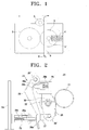
- FIG. 1 is a conceptual diagram explaining how a fixing roller in a related art fusing device is pressured and released.
- a related art fusing device 1 includes a heating roller 2 which heats the paper, a pressure roller 3 which provides pressure when in contact with the heating roller 2, a pressure spring 4 which presses the rotational axis 3' of the pressure roller 3 towards the heating roller 2 and maintains pressure on the pressure roller 3, and a pressure release member 6 disposed on the side of the rotational axis 3' opposite the pressure spring 4 which releases pressure by pushing the rotational axis 3' of the pressure roller 3 in the direction of the pressure spring 4 according to the rotation of a cam 5.
- the pressure supplied by the pressure roller 3 is maintained or released according to a rotation of the cam 5. That is, in order to release the pressure, the installed cam 5 rotates according to the method described above, and the pressure release member 6 releases the pressure by pushing the pressure roller 3 away from the heating roller 2 while rotating around a hinge 6' towards the pressure spring 4. If the cam 5 rotates in the opposite direction, pressure is added to the pressure roller 3 using the pressure spring 4.
- the pressure roller 3 When the cover of the image forming apparatus is opened for purposes of maintenance or the like, for example, when paper is jammed between the heating roller 2 and the pressure roller 3 during image formation, or when the cover is closed in order to operate the image forming apparatus, the pressure roller 3 should be pressured or released, and so the opening and closing of the cover and the rotation of the cam should occur together.
- One suggested method uses a position detection sensor on the cam, and a power source which moves the cam so the position of the cam can be adjusted according to the opening and closing of the cover.
- a second suggested method adjusts the angle of the cam according to whether the cover is open or shut by installing a lever attached to one side of the cover and connecting the other side of the cover to part of the cam.
- a problem with this second suggested method is that the reliability of the high pressure release function may drop if the configuration changes due to changes in the lever or cam caused by the high temperature of the heating roller or wear and tear of the cam parts.
- An aspect of the present invention provides a fusing device in an image forming apparatus which resolves at least the above and/or other problems, reduces pressure in the fusing apparatus through the cover of the image forming apparatus being opened with minimal effort by the user, and increases pressure supplied by the pressure roller in a stable fashion when the cover is closed.
- Another aspect of the present invention is to provide an image forming apparatus comprising the aforementioned fusing device.
- a fusing device of an image forming apparatus includes a fusing unit having a heating roller and a pressure roller which contact with other and are operable to rotate together, a cover which opens and closes the fusing unit, and a pressure and release unit, including a rotational shaft to which the pressure and release unit is rotatably fixed at one end, and a member having a pressuring part that is operable to transmit pressure to the pressure roller in a direction of the heating roller if the cover is shut and a pressured part pressured by the cover and disposed farther than the pressuring part from the rotational shaft.
- the cover includes a pressure boss to transmit the pressure to the pressured part.
- the pressure and release unit further includes a second rotational shaft to which another end of the pressure and release unit opposite the one end is rotatably attached, and a second member having a second pressure boss pressured by the pressuring part, and a second pressuring part that is closer than the second pressure boss to the second rotational shaft and is operable to transmit pressure to the pressure roller.
- the second pressure boss is attached to the second pressuring part.
- a second spring inside of the second pressure boss should be stiffer than a spring inside of the first pressure boss.
- the second pressuring part is a side of a recess in which a rotational shaft of the pressure roller is rotatably inserted and which presses the pressure roller in a direction of the heating roller when the cover is closed.
- the second pressuring part includes a stopper to limit a rotation of the member to a predetermined internal range.
- an image forming apparatus includes a document feed device which is operable to pick up a document from a feeding tray and to feed the document along a feed path, a developing device which is operable to apply developing materials to an electrostatic latent image to develop the electrostatic latent image, a transfer device which is operable to transfer the developing materials onto the document, and the pressure and release unit described above, which is operable to fuse the developing materials onto the document.
- FIG. 2 shows an embodiment of the fusing device according to an embodiment of the present invention.
- the fusing device 20 of FIG. 2 includes a heating roller 21 which provides heat, and which a recording medium having a developed image passes by; a pressure roller 22, which faces the heating roller and provides pressure; and a pressure and release unit 23, also known as a lever unit, which provides pressure to and releases the pressure from the above pressure roller 21.
- the recording medium may be various types of recording media, such as paper, transparency sheets, etc.
- the pressure and release unit 23 is formed as a two-level lever. As is illustrated in FIG. 2 , a first pressure boss 25 is disposed on the inside of a cover 24. A first sliding component 25a is supported by a spring 25b inside the first pressure boss 25. The first pressure boss 25 contacts and transmits pressure to the first pressured part 26a formed on the end of a first member 26, which rotates around a first rotating shaft 26'. It is understood that the first rotating shaft 26' may instead be a hinge or any other component which rotates around a rotational axis.
- the first member 26 also known as a first lever, includes a first pressuring part 26b disposed closer than the first pressured part 26a to the first rotating shaft 26', and transmits the pressure received from the first pressured part 26a to the first pressuring part 26b, which is amplified according to the principle of leverage.
- a stopper 27 is installed so that when the cover 24 is closed, an area of movement of the first member 26 is restricted and the amount of pressure transmitted to the first pressured part 26a does not exceed a certain limit.
- the second member 28 also known as a second lever, includes a second rotating shaft 28', a second pressure boss 29 (also referred to as a second pressured part), and a channel 30 (also referred to as the second pressuring part) which transmits pressure to the pressure roller 22 through the rotating axis of the pressure roller 22, retransmitting pressure which is again amplified by the principle of leverage.
- the second pressuring part 30 is preferably a side of a recess in which a rotational shaft of the pressure roller 22 is rotatably inserted and which presses the pressure roller 22 towards the heating roller 21 when the cover 24 is closed.
- the second pressuring part 30 is not limited to being a side of a recess, and instead may be various other components to engage a roller, such as a hollow protrusion. It is further understood that the second rotating shaft 28' may instead be a hinge or any other component which rotates around a rotational axis.
- the strength, that is, the stiffness, of the spring 29b built into the second pressure boss 29 is greater than the strength of the spring 25b built into the first pressure boss 25.
- a second sliding component 29a is supported by the spring 29b.
- the springs 25b and 29b of the first and second pressure bosses 25 and 29, respectively are able to conserve a fixed amount of energy, even if energy exceeding the minimum energy levels which the springs 25b and 29b need to press the pressure roller 22 into the heating roller 21 is transmitted to the pressure roller 22, pressure builds up in the springs 25b and 29b, and pressure can be released from the pressure roller 22 by opening the cover 24 , or the cover 24 can be prevented from opening to maintain the energy levels.
- the ratio between the length from the first rotational shaft 26' to the first pressuring part 26b and the length from the first rotational shaft 26' to the first pressured part 26a is preferably, but not necessarily, about 11:73.5.
- the ratio between the length from the second rotational shaft 28' to the second pressuring part 30 and the length from the second rotational shaft 28' to the second pressured boss 29 which is the second pressured part is preferably, but not necessarily, about 23:55.
- FIG. 3 illustrates an embodiment in which the pressure of the pressure roller 22 is released.
- the pressure of the first pressured part 26a is released.
- the first member 26 rotates around the first rotational shaft 26' in the direction of the cover 24, so the first pressuring part 26b is released.
- the second member 28 rotates around the second revolving shaft in the direction of the cover 24 due to the elasticity of the heating roller 21 and the pressure roller 22.
- the pressure pressing the pressure roller 22 into contact with the heating roller 21 is removed.
- FIG. 4 illustrates an image forming apparatus including a fusing device according to aspects of the present invention.
- the image forming apparatus 40 of FIG. 4 includes a document feed device 41 which picks up the document from the paper tray and feeds the document along a predetermined feed path, a developing device 42 which applies developing materials to an electrostatic latent image and develops the image, a transfer device 43 which transfers the developed image onto the document, and a fusing apparatus 20, as described above.
- the fusing device may be used with various types of image forming apparatuses other than the type shown in FIG. 4 , including, for example, ink jet printers.
- the image forming apparatus is not required to have an S-type feed path, and may instead have other types of feed paths, such as a C-type feed path, as well as other components instead of or in addition to those components shown in FIG. 4 and described above.
- the fusing device of the image forming apparatus provides a two-ended lever, so the user can open the cover of the image forming apparatus with little effort and release the pressure from the fusing device, and provides a fusing device of an image forming apparatus which adds pressure to the fusing device in a stable fashion when the cover is closed.
Landscapes
- Physics & Mathematics (AREA)
- General Physics & Mathematics (AREA)
- Fixing For Electrophotography (AREA)
- Ink Jet (AREA)
- Electrophotography Configuration And Component (AREA)
Description
- The present invention relates to a fusing device of an image forming apparatus, and more specifically, to a device which releases the pressure between rollers used in fusing an electrostatic latent image onto print material.
- Image forming apparatuses generally include a paper feed device which picks up paper from a feeding tray and feeds the paper along a feed path, a developing device which applies developing materials to an electrostatic latent image and develops the image, a transfer device which transfers the developed image onto the paper, and a fusing device which fuses the developed image onto a surface of the paper using heat and pressure.
-
FIG. 1 is a conceptual diagram explaining how a fixing roller in a related art fusing device is pressured and released. As shown inFIG. 1 , a relatedart fusing device 1 includes aheating roller 2 which heats the paper, apressure roller 3 which provides pressure when in contact with theheating roller 2, apressure spring 4 which presses the rotational axis 3' of thepressure roller 3 towards theheating roller 2 and maintains pressure on thepressure roller 3, and apressure release member 6 disposed on the side of the rotational axis 3' opposite thepressure spring 4 which releases pressure by pushing the rotational axis 3' of thepressure roller 3 in the direction of thepressure spring 4 according to the rotation of a cam 5. - In such a configuration, the pressure supplied by the
pressure roller 3 is maintained or released according to a rotation of the cam 5. That is, in order to release the pressure, the installed cam 5 rotates according to the method described above, and thepressure release member 6 releases the pressure by pushing thepressure roller 3 away from theheating roller 2 while rotating around a hinge 6' towards thepressure spring 4. If the cam 5 rotates in the opposite direction, pressure is added to thepressure roller 3 using thepressure spring 4. - When the cover of the image forming apparatus is opened for purposes of maintenance or the like, for example, when paper is jammed between the
heating roller 2 and thepressure roller 3 during image formation, or when the cover is closed in order to operate the image forming apparatus, thepressure roller 3 should be pressured or released, and so the opening and closing of the cover and the rotation of the cam should occur together. - In a related art fusing device, various mechanisms have been suggested in order to achieve this joint opening and closing. One suggested method uses a position detection sensor on the cam, and a power source which moves the cam so the position of the cam can be adjusted according to the opening and closing of the cover.
- However, if a separate power source and position detection sensor are used as described above, these added components increase costs, and if the system suddenly halts during operation (for example, due to power being cut or a lightning strike), the reliability of the high pressure release function also drops, or additional costs are required to maintain reliability.
- A second suggested method adjusts the angle of the cam according to whether the cover is open or shut by installing a lever attached to one side of the cover and connecting the other side of the cover to part of the cam. However, a problem with this second suggested method is that the reliability of the high pressure release function may drop if the configuration changes due to changes in the lever or cam caused by the high temperature of the heating roller or wear and tear of the cam parts.
- An aspect of the present invention provides a fusing device in an image forming apparatus which resolves at least the above and/or other problems, reduces pressure in the fusing apparatus through the cover of the image forming apparatus being opened with minimal effort by the user, and increases pressure supplied by the pressure roller in a stable fashion when the cover is closed.
- Another aspect of the present invention is to provide an image forming apparatus comprising the aforementioned fusing device.
- According to the present invention there is provided an apparatus and method as set forth in the appended claims. Preferred features of the invention will be apparent from the dependent claims, and the description which follows.
- According to an aspect of the present invention, a fusing device of an image forming apparatus includes a fusing unit having a heating roller and a pressure roller which contact with other and are operable to rotate together, a cover which opens and closes the fusing unit, and a pressure and release unit, including a rotational shaft to which the pressure and release unit is rotatably fixed at one end, and a member having a pressuring part that is operable to transmit pressure to the pressure roller in a direction of the heating roller if the cover is shut and a pressured part pressured by the cover and disposed farther than the pressuring part from the rotational shaft.
- Preferably, the cover includes a pressure boss to transmit the pressure to the pressured part.
- Preferably, the pressure and release unit further includes a second rotational shaft to which another end of the pressure and release unit opposite the one end is rotatably attached, and a second member having a second pressure boss pressured by the pressuring part, and a second pressuring part that is closer than the second pressure boss to the second rotational shaft and is operable to transmit pressure to the pressure roller.
- Preferably, the second pressure boss is attached to the second pressuring part.
- Preferably, a second spring inside of the second pressure boss should be stiffer than a spring inside of the first pressure boss.
- Preferably, the second pressuring part is a side of a recess in which a rotational shaft of the pressure roller is rotatably inserted and which presses the pressure roller in a direction of the heating roller when the cover is closed.
- Preferably, the second pressuring part includes a stopper to limit a rotation of the member to a predetermined internal range.
- According to another aspect of the present invention, an image forming apparatus includes a document feed device which is operable to pick up a document from a feeding tray and to feed the document along a feed path, a developing device which is operable to apply developing materials to an electrostatic latent image to develop the electrostatic latent image, a transfer device which is operable to transfer the developing materials onto the document, and the pressure and release unit described above, which is operable to fuse the developing materials onto the document.
- Additional aspects and/or advantages of the invention will be set forth in part in the description which follows and, in part, will be obvious from the description, or may be learned by practice of the invention.
- For a better understanding of the invention, and to show how embodiments of the same may be carried into effect, reference will now be made, by way of example, to the accompanying diagrammatic drawings in which:
-
FIG. 1 conceptually shows the pressure and release of a fusing roller in a related art fusing apparatus; -
FIG. 2 shows an embodiment of the fusing device according to an embodiment of the present invention; -
FIG. 3 shows a state of the pressure roller shown inFIG. 2 in which the pressure has been released; and -
FIG. 4 shows an image forming apparatus having the fusing device shown inFIG. 2 . - Reference will now be made in detail to the present embodiments of the present invention, examples of which are illustrated in the accompanying drawings, wherein like reference numerals refer to the like elements throughout. The embodiments are described below in order to explain the present invention by referring to the figures.
-
FIG. 2 shows an embodiment of the fusing device according to an embodiment of the present invention. Thefusing device 20 ofFIG. 2 includes aheating roller 21 which provides heat, and which a recording medium having a developed image passes by; apressure roller 22, which faces the heating roller and provides pressure; and a pressure andrelease unit 23, also known as a lever unit, which provides pressure to and releases the pressure from theabove pressure roller 21. It is understood that the recording medium may be various types of recording media, such as paper, transparency sheets, etc. - The pressure and
release unit 23 is formed as a two-level lever. As is illustrated inFIG. 2 , afirst pressure boss 25 is disposed on the inside of acover 24. A first slidingcomponent 25a is supported by aspring 25b inside thefirst pressure boss 25. Thefirst pressure boss 25 contacts and transmits pressure to the first pressuredpart 26a formed on the end of afirst member 26, which rotates around a first rotating shaft 26'. It is understood that the first rotating shaft 26' may instead be a hinge or any other component which rotates around a rotational axis. - The
first member 26, also known as a first lever, includes a first pressuringpart 26b disposed closer than the first pressuredpart 26a to the first rotating shaft 26', and transmits the pressure received from the first pressuredpart 26a to the first pressuringpart 26b, which is amplified according to the principle of leverage. - On the other side of the first pressured
part 26a of thefirst member 26, astopper 27 is installed so that when thecover 24 is closed, an area of movement of thefirst member 26 is restricted and the amount of pressure transmitted to the first pressuredpart 26a does not exceed a certain limit. - The
second member 28, also known as a second lever, includes a second rotating shaft 28', a second pressure boss 29 (also referred to as a second pressured part), and a channel 30 (also referred to as the second pressuring part) which transmits pressure to thepressure roller 22 through the rotating axis of thepressure roller 22, retransmitting pressure which is again amplified by the principle of leverage. As shown inFIG. 2 , the second pressuringpart 30 is preferably a side of a recess in which a rotational shaft of thepressure roller 22 is rotatably inserted and which presses thepressure roller 22 towards theheating roller 21 when thecover 24 is closed. However, it is understood that the second pressuringpart 30 is not limited to being a side of a recess, and instead may be various other components to engage a roller, such as a hollow protrusion. It is further understood that the second rotating shaft 28' may instead be a hinge or any other component which rotates around a rotational axis. - As the
second pressure boss 29, which is the second pressured part, receives the amplified power according to the construction described above, it is desirable that the strength, that is, the stiffness, of thespring 29b built into thesecond pressure boss 29 is greater than the strength of thespring 25b built into thefirst pressure boss 25. A second slidingcomponent 29a is supported by thespring 29b. Moreover, since thesprings second pressure bosses springs pressure roller 22 into theheating roller 21 is transmitted to thepressure roller 22, pressure builds up in thesprings pressure roller 22 by opening thecover 24 , or thecover 24 can be prevented from opening to maintain the energy levels. - The ratio between the length from the first rotational shaft 26' to the first pressuring
part 26b and the length from the first rotational shaft 26' to the first pressuredpart 26a is preferably, but not necessarily, about 11:73.5. Moreover, the ratio between the length from the second rotational shaft 28' to the second pressuringpart 30 and the length from the second rotational shaft 28' to the second pressuredboss 29 which is the second pressured part is preferably, but not necessarily, about 23:55. Using these preferred ratios, in order to press the pressure roller with a force of, for example, 10kgf , the size of the force to be applied to the cover decreases to 10*23/55*11/73.5 = 0.626 kgf = 626 gf, so the force which should be applied to the cover is reduced by about 16 times. It is understood that other ratios may also be used to configure the structure of the fusing device. -
FIG. 3 illustrates an embodiment in which the pressure of thepressure roller 22 is released. Referring toFIG. 3 , when thecover 24 is opened, the pressure of the first pressuredpart 26a is released. Specifically, when thecover 24 is opened, thefirst member 26 rotates around the first rotational shaft 26' in the direction of thecover 24, so the first pressuringpart 26b is released. When the first pressuringpart 26b is released, while the pressure of thesecond pressure boss 29, which is the second pressured part, is released, thesecond member 28 rotates around the second revolving shaft in the direction of thecover 24 due to the elasticity of theheating roller 21 and thepressure roller 22. Thus, the pressure pressing thepressure roller 22 into contact with theheating roller 21 is removed. -
FIG. 4 illustrates an image forming apparatus including a fusing device according to aspects of the present invention. Theimage forming apparatus 40 ofFIG. 4 includes adocument feed device 41 which picks up the document from the paper tray and feeds the document along a predetermined feed path, a developingdevice 42 which applies developing materials to an electrostatic latent image and develops the image, atransfer device 43 which transfers the developed image onto the document, and afusing apparatus 20, as described above. It is understood that the fusing device according to aspects of the present invention may be used with various types of image forming apparatuses other than the type shown inFIG. 4 , including, for example, ink jet printers. Additionally, it is understood that the image forming apparatus is not required to have an S-type feed path, and may instead have other types of feed paths, such as a C-type feed path, as well as other components instead of or in addition to those components shown inFIG. 4 and described above. - The fusing device of the image forming apparatus according to aspects of the present invention provides a two-ended lever, so the user can open the cover of the image forming apparatus with little effort and release the pressure from the fusing device, and provides a fusing device of an image forming apparatus which adds pressure to the fusing device in a stable fashion when the cover is closed.
- Although a few preferred embodiments have been shown and described, it will be appreciated by those skilled in the art that various changes and modifications might be made without departing from the scope of the invention, as defined in the appended claims.
Claims (18)
- A fusing device of an image forming apparatus, comprising:a fusing unit having a heating roller (21) and a pressure roller (22) which contact each other and are operable to rotate together;a cover (24) to access the fusing unit, which is operable to be pushed closed when pressure is applied thereto; anda lever unit (23) disposed between the fusing unit and the cover (24), comprising:a first rotational shaft (26'),a first lever (26) rotatably attached at one end to the first rotational shaft (26') and having a first pressured part (26a) which is operable to receive the pressure from the cover (24) and a first pressuring part (26b) on the same side of the first rotational shaft (26') as the first pressured part (26a) wherein the first pressuring part (26b) is operable to transmit and amplify the pressure by moving a shorter rotational distance than a rotational distance moved by the pressured part (26a),a second rotational shaft (28'), anda second lever (28) rotatably attached at one end to the second rotational shaft (28') and having a second pressured part (29) which is operable to receive the amplified pressure from the first pressuring part (26b) and a second pressuring part (30) which is operable to transmit and re-amplify the amplified pressure to the pressure roller (22) in a direction towards the heating roller (21) by moving a shorter rotational distance than a rotational distance moved by the second pressured part (29).
- The fusing device of claim 1, wherein the cover (24) comprises a pressure boss (25) to transmit the pressure applied to the cover (24) to the first pressured part (26a).
- The fusing device of claim 2, wherein the pressure boss (25) comprises:a spring (25b) disposed inside of the pressure boss (25); anda sliding component (25a) attached to the spring (25b) and which protrudes outside of the pressure boss (25) and contacts the first pressured part (26a).
- The fusing device of claim 3, wherein the second pressured part (29) comprises a second pressure boss (29), comprising:a second spring (29b) disposed inside of the second pressure boss (29); anda second sliding component (29a) attached to the second spring (29b) and which protrudes outside of the second pressure boss (29) and is pressed by the first pressuring part (26b).
- The fusing device of claim 4, wherein a stiffness of the second spring (29b) is greater than a stiffness of the first spring (25b).
- The fusing device of any preceding claim, wherein the second pressuring part (30) is a side of a recess in which a rotational shaft (26') of the pressure roller (22) is rotatably inserted and which is operable to press the pressure roller (22) in a direction of the heating roller (21) when the cover (24) is closed.
- The fusing device of any preceding claim, comprising a stopper (27) to limit a rotation of the first lever (26) to a predetermined internal range.
- The fusing device of any preceding claim, wherein a ratio between a length from the first rotational shaft (26') to the first pressuring part (26b) and a length from the first rotational shaft (26') to the first pressured part (26a) is approximately 11:73.5.
- The fusing device of any preceding claim, wherein a ratio between a length from the second rotational shaft (28') to the second pressuring part (30) and a length from the second rotational shaft (28') to the second pressured part (29) is approximately 23:55.
- An image forming apparatus, comprising:a document feed device (41) which is operable to pick up a document from a feeding tray and to feed the document along a feed path;a developing device (42) which is operable to apply developing materials to an electrostatic latent image to develop the electrostatic latent image;a transfer device (43) which is operable to transfer the developing materials onto the document; anda fusing device as claimed in claim 1.
- The image forming apparatus of claim 10, wherein the cover (24) comprises a pressure boss (25) to transmit the pressure applied to the cover (24) to the first pressured part (26a).
- The image forming apparatus of claim 11, wherein the pressure boss (25) comprises:a spring (25b) disposed inside of the pressure boss (25); and
a sliding component (25a) attached to the spring (25b) and which protrudes outside of the pressure boss (25) and contacts the first pressured part (26a). - The image forming device of claim 12, wherein the second pressured part (29) comprises a second pressure boss (29), comprising:a second spring (29b) disposed inside of the second pressure boss (29); anda second sliding component (29a) attached to the second spring (29b) and which protrudes outside of the second pressure boss (29) and is pressed by the first pressuring part (26b).
- The image forming device of claim 13, wherein a stiffness of the second spring (29b) is greater than a stiffness of the first spring (25b).
- The image forming device of any of claims 10 to 14, wherein the second pressuring part (30) is a side of a recess in which a rotational shaft (26') of the pressure roller (22) is rotatably inserted and which is operable to press the pressure roller (22) in a direction of the heating roller (21) when the cover (24) is closed.
- The image forming device of any of claims 10 to 15, comprising a stopper (27) to limit a rotation of the first lever (26) to a predetermined internal range.
- The image forming device of any of claims 10 to 16, wherein a ratio between a length from the first rotational shaft (26') to the first pressuring part (26b) and a length from the first rotational shaft (26') to the first pressured part (26a) is approximately 11:73.5.
- The image forming device of any of claims 10 to 17, wherein wherein a ratio between a length from the second rotational shaft (28') to the second pressuring part (30) and a length from the second rotational shaft (28') to the second pressured part (29) is approximately 23:55.
Applications Claiming Priority (1)
| Application Number | Priority Date | Filing Date | Title |
|---|---|---|---|
| KR1020060089822A KR101288326B1 (en) | 2006-09-15 | 2006-09-15 | Fusing device and Image Forming Apparatus having the same |
Publications (2)
| Publication Number | Publication Date |
|---|---|
| EP1901136A1 EP1901136A1 (en) | 2008-03-19 |
| EP1901136B1 true EP1901136B1 (en) | 2015-03-04 |
Family
ID=38871539
Family Applications (1)
| Application Number | Title | Priority Date | Filing Date |
|---|---|---|---|
| EP07111304.7A Not-in-force EP1901136B1 (en) | 2006-09-15 | 2007-06-28 | Fusing device and image forming apparatus having the same |
Country Status (4)
| Country | Link |
|---|---|
| US (1) | US7953348B2 (en) |
| EP (1) | EP1901136B1 (en) |
| KR (1) | KR101288326B1 (en) |
| CN (1) | CN101145016B (en) |
Families Citing this family (17)
| Publication number | Priority date | Publication date | Assignee | Title |
|---|---|---|---|---|
| US8385800B2 (en) * | 2006-08-25 | 2013-02-26 | Brother Kogyo Kabushiki Kaisha | Fixing device for image forming device, capable of adjusting nip force between heating roller and pressure roller |
| EP3373078B1 (en) * | 2009-04-07 | 2024-06-05 | Canon Kabushiki Kaisha | Image forming apparatus |
| US8340546B2 (en) | 2010-04-06 | 2012-12-25 | Xerox Corporation | Dual function charging device and charge patterning device cleaner |
| JP5316564B2 (en) | 2010-09-30 | 2013-10-16 | ブラザー工業株式会社 | Image forming apparatus |
| JP5282796B2 (en) * | 2011-02-25 | 2013-09-04 | ブラザー工業株式会社 | Image forming apparatus |
| JP6366319B2 (en) * | 2013-04-18 | 2018-08-01 | キヤノン株式会社 | Image forming apparatus and fixing unit |
| TWM480093U (en) * | 2014-02-18 | 2014-06-11 | Avision Inc | Separable fusing device and printer using the same |
| JP6409601B2 (en) * | 2015-02-06 | 2018-10-24 | ブラザー工業株式会社 | Image forming apparatus |
| JP6537012B2 (en) * | 2015-02-17 | 2019-07-03 | 富士ゼロックス株式会社 | Image forming apparatus and fixing device |
| JP2017107034A (en) * | 2015-12-09 | 2017-06-15 | 京セラドキュメントソリューションズ株式会社 | Fixing apparatus and image forming apparatus having the same |
| JP6665689B2 (en) * | 2016-05-31 | 2020-03-13 | 株式会社リコー | Pressure depressurizing device, fixing device and image forming device |
| JP6617670B2 (en) * | 2016-09-21 | 2019-12-11 | 京セラドキュメントソリューションズ株式会社 | Fixing apparatus and image forming apparatus |
| JP6658566B2 (en) * | 2017-01-24 | 2020-03-04 | 京セラドキュメントソリューションズ株式会社 | Image forming device |
| JP6958029B2 (en) * | 2017-07-03 | 2021-11-02 | 富士フイルムビジネスイノベーション株式会社 | Assembly attachment / detachment structure and image forming device |
| JP7543118B2 (en) * | 2020-12-14 | 2024-09-02 | キヤノン株式会社 | Image forming device |
| JP7841265B2 (en) * | 2022-01-31 | 2026-04-07 | ブラザー工業株式会社 | Image forming apparatus |
| JP7836511B2 (en) * | 2022-03-16 | 2026-03-27 | 株式会社リコー | Pressure/depressurization switching mechanism and image forming apparatus |
Family Cites Families (9)
| Publication number | Priority date | Publication date | Assignee | Title |
|---|---|---|---|---|
| JPS5814872A (en) * | 1981-07-20 | 1983-01-27 | Fuji Xerox Co Ltd | Roller type fixing device of copying machine |
| JPH07295429A (en) | 1994-04-21 | 1995-11-10 | Katsuragawa Electric Co Ltd | Image forming device |
| JP3905268B2 (en) | 1999-11-05 | 2007-04-18 | 株式会社リコー | Image forming apparatus |
| JP3627702B2 (en) * | 2001-12-20 | 2005-03-09 | ブラザー工業株式会社 | Image forming apparatus |
| KR100465322B1 (en) * | 2002-07-19 | 2005-01-13 | 삼성전자주식회사 | Fusing apparatus for laser printer |
| ITMI20040154U1 (en) | 2004-04-08 | 2004-07-08 | Agostino Ferrari Spa | SHOCK ABSORBER FOR MOVABLE PARTS OF A FURNITURE |
| JP4732027B2 (en) | 2004-06-30 | 2011-07-27 | 株式会社リコー | Fixing apparatus and image forming apparatus |
| JP4741891B2 (en) * | 2005-06-29 | 2011-08-10 | 株式会社リコー | Transfer device and image forming apparatus |
| US7515850B2 (en) * | 2005-09-30 | 2009-04-07 | Ricoh Company Ltd. | Sheet conveying apparatus and image forming apparatus |
-
2006
- 2006-09-15 KR KR1020060089822A patent/KR101288326B1/en not_active Expired - Fee Related
-
2007
- 2007-04-17 US US11/736,194 patent/US7953348B2/en active Active
- 2007-05-22 CN CN2007101048582A patent/CN101145016B/en not_active Expired - Fee Related
- 2007-06-28 EP EP07111304.7A patent/EP1901136B1/en not_active Not-in-force
Also Published As
| Publication number | Publication date |
|---|---|
| EP1901136A1 (en) | 2008-03-19 |
| CN101145016B (en) | 2012-08-15 |
| KR20080025252A (en) | 2008-03-20 |
| KR101288326B1 (en) | 2013-07-19 |
| US7953348B2 (en) | 2011-05-31 |
| US20080069589A1 (en) | 2008-03-20 |
| CN101145016A (en) | 2008-03-19 |
Similar Documents
| Publication | Publication Date | Title |
|---|---|---|
| US7953348B2 (en) | Fusing device and image forming apparatus having the same | |
| US7734202B2 (en) | Apparatus for adjusting fixing pressure and image forming apparatus having the same | |
| KR101473874B1 (en) | Fusing unit and image forming apparatus having the same | |
| CN101276164B (en) | Image forming apparatus | |
| EP2587314B1 (en) | Image forming apparatus | |
| US8606141B2 (en) | Image forming apparatus operable for installing attachable/detachable cartidge therein | |
| CN103376695B (en) | Image forming apparatus with a toner supply unit | |
| JP5500416B2 (en) | Interlock switch and image forming apparatus using the same | |
| EP3464137B1 (en) | Sheet supplying apparatus | |
| CN106006104A (en) | Image forming apparatus | |
| US9377748B2 (en) | Image forming apparatus | |
| EP2477076B1 (en) | Fixing device | |
| JP2000079739A (en) | Opening / closing cover locking device and image forming apparatus | |
| KR100561369B1 (en) | Image Forming Device | |
| US7448623B2 (en) | Paper feeding mechanism and image forming apparatus employing the same | |
| JP2004045585A (en) | Cover opening / closing mechanism of image processing apparatus and image processing apparatus | |
| US9507305B2 (en) | Fixing device having nip pressure adjustment and image forming apparatus | |
| JP7558785B2 (en) | Image forming device | |
| JP2018077336A (en) | Image forming apparatus | |
| EP1553466B1 (en) | Image transfer element with leverage | |
| KR101235222B1 (en) | Fusing unit for image forming apparatus | |
| KR20080099514A (en) | Spacing control unit, fixing device and image forming apparatus including the same | |
| JP2007279565A (en) | Opening / closing mechanism of opening / closing unit | |
| KR101235218B1 (en) | A image fixing device of image forming apparatus | |
| JP2024177906A (en) | Transfer device and image forming device |
Legal Events
| Date | Code | Title | Description |
|---|---|---|---|
| PUAI | Public reference made under article 153(3) epc to a published international application that has entered the european phase |
Free format text: ORIGINAL CODE: 0009012 |
|
| AK | Designated contracting states |
Kind code of ref document: A1 Designated state(s): AT BE BG CH CY CZ DE DK EE ES FI FR GB GR HU IE IS IT LI LT LU LV MC MT NL PL PT RO SE SI SK TR |
|
| AX | Request for extension of the european patent |
Extension state: AL BA HR MK YU |
|
| 17P | Request for examination filed |
Effective date: 20080919 |
|
| AKX | Designation fees paid |
Designated state(s): DE FR GB NL |
|
| 17Q | First examination report despatched |
Effective date: 20120731 |
|
| RAP1 | Party data changed (applicant data changed or rights of an application transferred) |
Owner name: SAMSUNG ELECTRONICS CO., LTD. |
|
| REG | Reference to a national code |
Ref country code: DE Ref legal event code: R079 Ref document number: 602007040447 Country of ref document: DE Free format text: PREVIOUS MAIN CLASS: G03G0015200000 Ipc: G03G0021160000 |
|
| GRAP | Despatch of communication of intention to grant a patent |
Free format text: ORIGINAL CODE: EPIDOSNIGR1 |
|
| RIC1 | Information provided on ipc code assigned before grant |
Ipc: G03G 21/16 20060101AFI20140904BHEP Ipc: G03G 15/20 20060101ALI20140904BHEP |
|
| INTG | Intention to grant announced |
Effective date: 20141006 |
|
| GRAS | Grant fee paid |
Free format text: ORIGINAL CODE: EPIDOSNIGR3 |
|
| GRAA | (expected) grant |
Free format text: ORIGINAL CODE: 0009210 |
|
| AK | Designated contracting states |
Kind code of ref document: B1 Designated state(s): DE FR GB NL |
|
| REG | Reference to a national code |
Ref country code: GB Ref legal event code: FG4D |
|
| REG | Reference to a national code |
Ref country code: DE Ref legal event code: R096 Ref document number: 602007040447 Country of ref document: DE Effective date: 20150416 |
|
| REG | Reference to a national code |
Ref country code: NL Ref legal event code: T3 |
|
| REG | Reference to a national code |
Ref country code: DE Ref legal event code: R097 Ref document number: 602007040447 Country of ref document: DE |
|
| PLBE | No opposition filed within time limit |
Free format text: ORIGINAL CODE: 0009261 |
|
| STAA | Information on the status of an ep patent application or granted ep patent |
Free format text: STATUS: NO OPPOSITION FILED WITHIN TIME LIMIT |
|
| 26N | No opposition filed |
Effective date: 20151207 |
|
| GBPC | Gb: european patent ceased through non-payment of renewal fee |
Effective date: 20150628 |
|
| REG | Reference to a national code |
Ref country code: FR Ref legal event code: ST Effective date: 20160229 |
|
| PG25 | Lapsed in a contracting state [announced via postgrant information from national office to epo] |
Ref country code: GB Free format text: LAPSE BECAUSE OF NON-PAYMENT OF DUE FEES Effective date: 20150628 |
|
| PG25 | Lapsed in a contracting state [announced via postgrant information from national office to epo] |
Ref country code: FR Free format text: LAPSE BECAUSE OF NON-PAYMENT OF DUE FEES Effective date: 20150630 |
|
| REG | Reference to a national code |
Ref country code: NL Ref legal event code: PD Owner name: S-PRINTING SOLUTION CO., LTD.; KO Free format text: DETAILS ASSIGNMENT: CHANGE OF OWNER(S), ASSIGNMENT; FORMER OWNER NAME: SAMSUNG ELECTRONICS CO., LTD. Effective date: 20170221 |
|
| REG | Reference to a national code |
Ref country code: DE Ref legal event code: R082 Ref document number: 602007040447 Country of ref document: DE Representative=s name: HOEFER & PARTNER PATENTANWAELTE MBB, DE Ref country code: DE Ref legal event code: R082 Ref document number: 602007040447 Country of ref document: DE Ref country code: DE Ref legal event code: R081 Ref document number: 602007040447 Country of ref document: DE Owner name: HP PRINTING KOREA CO., LTD., SUWON-SI, KR Free format text: FORMER OWNER: SAMSUNG ELECTRONICS CO., LTD., SUWON-SI, GYEONGGI-DO, KR Ref country code: DE Ref legal event code: R081 Ref document number: 602007040447 Country of ref document: DE Owner name: HEWLETT-PACKARD DEVELOPMENT COMPANY, L.P., SPR, US Free format text: FORMER OWNER: SAMSUNG ELECTRONICS CO., LTD., SUWON-SI, GYEONGGI-DO, KR Ref country code: DE Ref legal event code: R081 Ref document number: 602007040447 Country of ref document: DE Owner name: S-PRINTING SOLUTION CO., LTD., SUWON-SI, KR Free format text: FORMER OWNER: SAMSUNG ELECTRONICS CO., LTD., SUWON-SI, GYEONGGI-DO, KR |
|
| REG | Reference to a national code |
Ref country code: NL Ref legal event code: HC Owner name: HP PRINTING KOREA CO., LTD.; KR Free format text: DETAILS ASSIGNMENT: CHANGE OF OWNER(S), CHANGE OF OWNER(S) NAME; FORMER OWNER NAME: S-PRINTING SOLUTION CO., LTD. Effective date: 20180816 |
|
| REG | Reference to a national code |
Ref country code: DE Ref legal event code: R082 Ref document number: 602007040447 Country of ref document: DE Ref country code: DE Ref legal event code: R081 Ref document number: 602007040447 Country of ref document: DE Owner name: HP PRINTING KOREA CO., LTD., SUWON-SI, KR Free format text: FORMER OWNER: S-PRINTING SOLUTION CO., LTD., SUWON-SI, GYEONGGI-DO, KR Ref country code: DE Ref legal event code: R081 Ref document number: 602007040447 Country of ref document: DE Owner name: HEWLETT-PACKARD DEVELOPMENT COMPANY, L.P., SPR, US Free format text: FORMER OWNER: S-PRINTING SOLUTION CO., LTD., SUWON-SI, GYEONGGI-DO, KR |
|
| REG | Reference to a national code |
Ref country code: NL Ref legal event code: PD Owner name: HEWLETT-PACKARD DEVELOPMENT COMPANY, L.P.; US Free format text: DETAILS ASSIGNMENT: CHANGE OF OWNER(S), CHANGE OF LEGAL ENTITY; FORMER OWNER NAME: SAMSUNG ELECTRONICS CO., LTD. Effective date: 20191030 |
|
| REG | Reference to a national code |
Ref country code: DE Ref legal event code: R081 Ref document number: 602007040447 Country of ref document: DE Owner name: HEWLETT-PACKARD DEVELOPMENT COMPANY, L.P., SPR, US Free format text: FORMER OWNER: HP PRINTING KOREA CO., LTD., SUWON-SI, GYEONGGI-DO, KR |
|
| PGFP | Annual fee paid to national office [announced via postgrant information from national office to epo] |
Ref country code: NL Payment date: 20220523 Year of fee payment: 16 |
|
| PGFP | Annual fee paid to national office [announced via postgrant information from national office to epo] |
Ref country code: DE Payment date: 20220518 Year of fee payment: 16 |
|
| REG | Reference to a national code |
Ref country code: DE Ref legal event code: R119 Ref document number: 602007040447 Country of ref document: DE |
|
| REG | Reference to a national code |
Ref country code: NL Ref legal event code: MM Effective date: 20230701 |
|
| PG25 | Lapsed in a contracting state [announced via postgrant information from national office to epo] |
Ref country code: NL Free format text: LAPSE BECAUSE OF NON-PAYMENT OF DUE FEES Effective date: 20230701 |
|
| PG25 | Lapsed in a contracting state [announced via postgrant information from national office to epo] |
Ref country code: DE Free format text: LAPSE BECAUSE OF NON-PAYMENT OF DUE FEES Effective date: 20240103 |