EP1901133A1 - Image forming device with toner leak preventing means - Google Patents
Image forming device with toner leak preventing means Download PDFInfo
- Publication number
- EP1901133A1 EP1901133A1 EP07014929A EP07014929A EP1901133A1 EP 1901133 A1 EP1901133 A1 EP 1901133A1 EP 07014929 A EP07014929 A EP 07014929A EP 07014929 A EP07014929 A EP 07014929A EP 1901133 A1 EP1901133 A1 EP 1901133A1
- Authority
- EP
- European Patent Office
- Prior art keywords
- toner
- image forming
- supplying
- developing device
- process unit
- Prior art date
- Legal status (The legal status is an assumption and is not a legal conclusion. Google has not performed a legal analysis and makes no representation as to the accuracy of the status listed.)
- Withdrawn
Links
- 238000000034 method Methods 0.000 claims abstract description 51
- 230000008569 process Effects 0.000 claims abstract description 51
- 230000007246 mechanism Effects 0.000 claims abstract description 20
- 239000002699 waste material Substances 0.000 claims description 49
- 238000004140 cleaning Methods 0.000 claims description 11
- 238000007599 discharging Methods 0.000 claims description 10
- 239000002245 particle Substances 0.000 claims description 7
- 230000006835 compression Effects 0.000 description 17
- 238000007906 compression Methods 0.000 description 17
- 230000010355 oscillation Effects 0.000 description 8
- 239000002390 adhesive tape Substances 0.000 description 6
- JOYRKODLDBILNP-UHFFFAOYSA-N Ethyl urethane Chemical compound CCOC(N)=O JOYRKODLDBILNP-UHFFFAOYSA-N 0.000 description 4
- 230000009471 action Effects 0.000 description 4
- 239000006260 foam Substances 0.000 description 4
- 238000011144 upstream manufacturing Methods 0.000 description 3
- 230000002093 peripheral effect Effects 0.000 description 2
- 239000011347 resin Substances 0.000 description 2
- 229920005989 resin Polymers 0.000 description 2
- 230000032258 transport Effects 0.000 description 2
- 239000000853 adhesive Substances 0.000 description 1
- 230000001070 adhesive effect Effects 0.000 description 1
- 230000003247 decreasing effect Effects 0.000 description 1
- 238000001514 detection method Methods 0.000 description 1
- 238000003780 insertion Methods 0.000 description 1
- 230000037431 insertion Effects 0.000 description 1
- 239000002184 metal Substances 0.000 description 1
- 239000000203 mixture Substances 0.000 description 1
- 238000012986 modification Methods 0.000 description 1
- 230000004048 modification Effects 0.000 description 1
- 238000000465 moulding Methods 0.000 description 1
- 230000003287 optical effect Effects 0.000 description 1
Images

Classifications
-
- G—PHYSICS
- G03—PHOTOGRAPHY; CINEMATOGRAPHY; ANALOGOUS TECHNIQUES USING WAVES OTHER THAN OPTICAL WAVES; ELECTROGRAPHY; HOLOGRAPHY
- G03G—ELECTROGRAPHY; ELECTROPHOTOGRAPHY; MAGNETOGRAPHY
- G03G21/00—Arrangements not provided for by groups G03G13/00 - G03G19/00, e.g. cleaning, elimination of residual charge
- G03G21/10—Collecting or recycling waste developer
-
- G—PHYSICS
- G03—PHOTOGRAPHY; CINEMATOGRAPHY; ANALOGOUS TECHNIQUES USING WAVES OTHER THAN OPTICAL WAVES; ELECTROGRAPHY; HOLOGRAPHY
- G03G—ELECTROGRAPHY; ELECTROPHOTOGRAPHY; MAGNETOGRAPHY
- G03G21/00—Arrangements not provided for by groups G03G13/00 - G03G19/00, e.g. cleaning, elimination of residual charge
- G03G21/10—Collecting or recycling waste developer
- G03G21/105—Arrangements for conveying toner waste
-
- G—PHYSICS
- G03—PHOTOGRAPHY; CINEMATOGRAPHY; ANALOGOUS TECHNIQUES USING WAVES OTHER THAN OPTICAL WAVES; ELECTROGRAPHY; HOLOGRAPHY
- G03G—ELECTROGRAPHY; ELECTROPHOTOGRAPHY; MAGNETOGRAPHY
- G03G15/00—Apparatus for electrographic processes using a charge pattern
- G03G15/06—Apparatus for electrographic processes using a charge pattern for developing
- G03G15/08—Apparatus for electrographic processes using a charge pattern for developing using a solid developer, e.g. powder developer
- G03G15/0822—Arrangements for preparing, mixing, supplying or dispensing developer
- G03G15/0848—Arrangements for testing or measuring developer properties or quality, e.g. charge, size, flowability
- G03G15/0849—Detection or control means for the developer concentration
- G03G15/0855—Detection or control means for the developer concentration the concentration being measured by optical means
-
- G—PHYSICS
- G03—PHOTOGRAPHY; CINEMATOGRAPHY; ANALOGOUS TECHNIQUES USING WAVES OTHER THAN OPTICAL WAVES; ELECTROGRAPHY; HOLOGRAPHY
- G03G—ELECTROGRAPHY; ELECTROPHOTOGRAPHY; MAGNETOGRAPHY
- G03G15/00—Apparatus for electrographic processes using a charge pattern
- G03G15/06—Apparatus for electrographic processes using a charge pattern for developing
- G03G15/08—Apparatus for electrographic processes using a charge pattern for developing using a solid developer, e.g. powder developer
- G03G15/0822—Arrangements for preparing, mixing, supplying or dispensing developer
- G03G15/0865—Arrangements for supplying new developer
-
- G—PHYSICS
- G03—PHOTOGRAPHY; CINEMATOGRAPHY; ANALOGOUS TECHNIQUES USING WAVES OTHER THAN OPTICAL WAVES; ELECTROGRAPHY; HOLOGRAPHY
- G03G—ELECTROGRAPHY; ELECTROPHOTOGRAPHY; MAGNETOGRAPHY
- G03G15/00—Apparatus for electrographic processes using a charge pattern
- G03G15/06—Apparatus for electrographic processes using a charge pattern for developing
- G03G15/08—Apparatus for electrographic processes using a charge pattern for developing using a solid developer, e.g. powder developer
- G03G15/0822—Arrangements for preparing, mixing, supplying or dispensing developer
- G03G15/0877—Arrangements for metering and dispensing developer from a developer cartridge into the development unit
- G03G15/0879—Arrangements for metering and dispensing developer from a developer cartridge into the development unit for dispensing developer from a developer cartridge not directly attached to the development unit
-
- G—PHYSICS
- G03—PHOTOGRAPHY; CINEMATOGRAPHY; ANALOGOUS TECHNIQUES USING WAVES OTHER THAN OPTICAL WAVES; ELECTROGRAPHY; HOLOGRAPHY
- G03G—ELECTROGRAPHY; ELECTROPHOTOGRAPHY; MAGNETOGRAPHY
- G03G15/00—Apparatus for electrographic processes using a charge pattern
- G03G15/06—Apparatus for electrographic processes using a charge pattern for developing
- G03G15/08—Apparatus for electrographic processes using a charge pattern for developing using a solid developer, e.g. powder developer
- G03G15/0822—Arrangements for preparing, mixing, supplying or dispensing developer
- G03G15/0877—Arrangements for metering and dispensing developer from a developer cartridge into the development unit
- G03G15/0881—Sealing of developer cartridges
- G03G15/0886—Sealing of developer cartridges by mechanical means, e.g. shutter, plug
-
- G—PHYSICS
- G03—PHOTOGRAPHY; CINEMATOGRAPHY; ANALOGOUS TECHNIQUES USING WAVES OTHER THAN OPTICAL WAVES; ELECTROGRAPHY; HOLOGRAPHY
- G03G—ELECTROGRAPHY; ELECTROPHOTOGRAPHY; MAGNETOGRAPHY
- G03G21/00—Arrangements not provided for by groups G03G13/00 - G03G19/00, e.g. cleaning, elimination of residual charge
-
- G—PHYSICS
- G03—PHOTOGRAPHY; CINEMATOGRAPHY; ANALOGOUS TECHNIQUES USING WAVES OTHER THAN OPTICAL WAVES; ELECTROGRAPHY; HOLOGRAPHY
- G03G—ELECTROGRAPHY; ELECTROPHOTOGRAPHY; MAGNETOGRAPHY
- G03G21/00—Arrangements not provided for by groups G03G13/00 - G03G19/00, e.g. cleaning, elimination of residual charge
- G03G21/10—Collecting or recycling waste developer
- G03G21/12—Toner waste containers
-
- G—PHYSICS
- G03—PHOTOGRAPHY; CINEMATOGRAPHY; ANALOGOUS TECHNIQUES USING WAVES OTHER THAN OPTICAL WAVES; ELECTROGRAPHY; HOLOGRAPHY
- G03G—ELECTROGRAPHY; ELECTROPHOTOGRAPHY; MAGNETOGRAPHY
- G03G2215/00—Apparatus for electrophotographic processes
- G03G2215/06—Developing structures, details
- G03G2215/066—Toner cartridge or other attachable and detachable container for supplying developer material to replace the used material
- G03G2215/0692—Toner cartridge or other attachable and detachable container for supplying developer material to replace the used material using a slidable sealing member, e.g. shutter
Definitions
- the present invention relates to an image forming device.
- the image forming device includes an image forming process unit having a developing device, and includes a toner containing portion arranged in relationship to the process unit. When the image forming process unit and the toner containing portion are connected, a toner transporting mechanism is constructed.
- An electrophotographic image forming device is frequently used in a copier, a facsimile machine, a printer, or a Multi Function Peripheral (MFP) including a copying function, a facsimile function, and/or a printing function.
- Some of such image forming devices use a developer including two components (toner and carrier).
- the image forming device includes an image forming process unit such as a developing device unit or a photoconductive drum unit, a toner supply hopper, and a waste toner collecting hopper.
- the toner supply hopper supplies the developing device unit with toner if required.
- the waste toner collecting hopper collects the transfer residual toner.
- the image forming process unit, the toner supply hopper, and the waste toner collecting hopper can be separately inserted into a device main body.
- the image forming process unit, the toner supply hopper, and the waste toner collecting hopper are connected, and thus, a toner transporting mechanism is constructed.
- the developing device unit and the photoconductive drum unit may be integrated to construct the image forming process unit.
- the toner supply hopper and the waste toner collecting hopper may also be integrated.
- the above-described image forming device includes a toner receiving/supplying portion arranged in the midst of the toner transporting mechanism.
- a toner receiving port and a toner supplying port of the toner receiving/supplying portion can be disconnectably connected to each other.
- the toner receiving/supplying portion since the toner is composed of microscopic particles, toner leakage cannot be prevented completely. Therefore, it is unavoidable that some amount of toner leaks and accumulates in the vicinity of the toner receiving/supplying portion. The leaked and accumulated toner does not greatly matter under a normal use condition. However, when changing a cartridged toner container or each process unit, since oscillations and impacts occur on a device body, the accumulated toner scatters.
- the toner is transferred and adhered to a mechanism portion, which affects an image quality, and the toner can stain user's clothing or hands.
- the toner scatters because of the following reason. That is, since a housing including the cartridge and the process unit is made of resin and metal, the toner accumulated on a surface of the housing is not fixed and can be easily detached by the oscillations and the impacts.
- some developing devices include a shutter arranged above a developing portion of the developing device such that two-sided adhesive tape is adhered to a portion of the shutter facing an inside of the developing portion.
- the developing device is inserted to a prescribed portion inside the image forming device under a state in which the shutter is open, a surface to which the two-sided adhesive tape is adhered faces upward, and a release paper of the two-sided adhesive tape is peeled off.
- an adhesive surface of the two-sided adhesive tape is exposed on an upper surface.
- paper scraps fell off from a paper feed cassette arranged above the developing device can be trapped by the two-sided adhesive tape. Accordingly, when drawing out the developing device, the paper scraps will not scatter and stain a surrounding area.
- the paper scraps fell off from the paper cassette is trapped by the two-sided adhesive tape adhered to the shutter of the developing device, however, it is not an intention of the conventional art to trap the leaked toner. Moreover, it is not an intention of the conventional art to trap the leaked toner in order that the toner unavoidably accumulated in the vicinity of the toner receiving/supplying portion can be prevented from scattering.
- components for forming an image such as the process unit or the toner cartridge, are changed as consumable components by a user.
- the toner receiving/supplying portion is arranged on a front side in an inserting direction of the components with respect to the device, the toner leaked and accumulated in the vicinity of the toner receiving/supplying portion is scattered by oscillations and impacts generated when changing the components, and the leaked and accumulated toner can stain the user's hands or clothing.
- preferred embodiments of the present invention provide an image forming device in which toner leaked from a toner receiving/supplying portion arranged in the midst of a toner transporting mechanism is trapped and prevented from scattering.
- an image forming process unit having a developing device and a toner containing portion arranged in relationship to the process unit are connected to construct a toner transporting mechanism.
- the toner transporting mechanism includes a toner receiving/supplying portion having a toner receiving port and a toner supplying port such that the toner receiving port and the toner supplying port are disconnectably connected to each other.
- a trapping member for trapping leaked toner is attached to a surface of a portion adjacent to the toner receiving/supplying portion.
- a shutter that is opened when the toner receiving/supplying portion is connected may be provided on a portion corresponding to the toner receiving/supplying portion in the toner transporting mechanism.
- a trapping member is preferably composed of a porous member including a plurality of micro cells that can absorb toner particles therein.
- the porous member open-cell urethane foam is preferably used.
- the image forming process unit and/or the toner containing portion are removably inserted into a device main body from a side portion of the device main body, and that the toner receiving/supplying portion is positioned on a front side in an inserting direction.
- the side portion includes front, rear, right, and left side portions.
- the trapping member for trapping the leaked toner is attached to the surface of the portion adjacent to the toner receiving/supplying portion, the leaked toner can be trapped and reliably held by the trapping member. Therefore, even when oscillations and impacts occur on the device, the leaked toner will not scatter. Accordingly, an image quality will not be affected, and hands and clothing of an operator (a user) will not be stained.
- the trapping member is composed of the porous member including the plurality of micro cells that can absorb the toner particles therein, the toner, which is composed of microscopic particles, is absorbed into the micro cells, trapped, and fixed.
- the open-cell urethane foam which can be reasonably obtained and easily handled, is used as the porous member.
- the image forming process unit and/or the toner containing portion is removably inserted into the device main body from the side portion of the device main body, and the toner receiving/supplying portion is positioned on the front side in the inserting direction. Therefore, when the user performs an inserting/removing operation of the process unit, concerns in which the hands and clothing of the user will be stained are reduced.
- Fig. 1 is a schematic longitudinal sectional view illustrating an image forming device according to a preferred embodiment of the present invention.
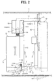
- Fig. 2 is a schematic plan view illustrating a configuration of a toner transporting mechanism of the image forming device.
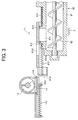
- Fig. 3 is a cross sectional view taken on line Y-Y in Fig. 2.
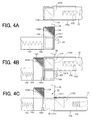
- Figs. 4A, 4B, and 4C are schematic plane view illustrating operations carried out at a portion indicated by "Z" in Fig. 2.
- An image forming device 100 in Fig. 1 is a printer as an example, including an electrophotographic recording unit.
- the present invention is not limited to such a printer, but may be a copier, a facsimile machine, or an MFP including a copying function, a facsimile function, and/or a printing function, having an image scanning device.
- a device main body 1 of the image forming device 100 includes a paper feed unit 2 for recording papers (papers), an electrophotographic image recording unit 3, and a discharge unit 4 for the printed recording papers such that the units 2, 3, and 4 are sequentially stacked in a height direction.
- the paper feed unit 2 for the recording papers has a paper feed cassette 201, a paper separating and feeding roller 202, and a separating pad 203.
- the paper feed cassette 201 can accommodate a plurality of stacked recording papers, and can be removably inserted into the device main body 1.
- the paper separating and feeding roller 202 is arranged at a front end portion in a paper feeding direction of the paper feed cassette 201.
- the separating pad 203 elastically makes contact with a circumferential surface of the paper separating and feeding roller 202.
- a plurality of cassettes similar to the paper feed cassette 201 may be stacked thereunder.
- An optional cassette (not illustrated) may also be provided.
- the image recording unit 3 includes a process portion and a fuser 11 arranged on a downstream side of the process portion.
- the process portion includes a photoconductive drum 5.
- a corona charger 6, an exposing unit 7 having a Light Emitting Diode (LED), a developing device 8, a transfer roller (a transfer device) 9, and a transfer residual toner cleaning device 10 are arranged in this order around the photoconductive drum 5. Excluding the exposing unit 7 and the transfer roller 9, the process portion is provided as a process unit including a drum unit 50 and a developing device unit 80.
- the drum unit 50 collectively includes the photoconductive drum 5, the charger 6, and the transfer residual toner cleaning device 10.
- the developing device unit 80 collectively includes a developing device housing 81, agitating and transporting screws 82, 83, a supply paddle 84, and a developing roller 85.
- the drum unit 50 and the developing device unit 80 can be removably inserted into the device main body 1 from a front surface side of the device main body 1 separately or under a state in which the units 50 and 80 are combined by some joining member.
- the entire process portion excluding the exposing unit 7 and the transfer roller 9 may be collectively provided as a unitary process unit.
- the process unit can be changed as a consumable unit to a new unit if required.
- the front surface side of the device main body 1 refers to a front side in Fig. 1.
- the paper feed cassette 201 can be removably inserted into the device main body 1 from the front surface side.
- the developing device unit 80 is a developing device which uses a developer including two components.
- the developing device housing 81 is foamed by resin molding and also used as a developer container. Toner and carrier are contained in the developing device housing 81.
- the two mutually parallel agitating and transporting screws 82 and 83 agitate and transport the toner.
- the supply paddle 84 supplies the biased developing roller 85 with the developer.
- a magnetic sensor 86 is provided on an outer surface of the developing device housing 81. The magnetic sensor 86 detects a toner concentration (mixture ratio of the toner and the carrier) inside the developing device housing 81.
- a toner container 12 and a toner supplying hopper 13 as a toner containing portion are arranged at a position that is spaced apart from the developing device unit 80.
- the toner is supplied from the toner hopper 13 into the developing device housing 81 via a screw conveyor (a pipe screw) 14.
- An agitator 121 and a toner feeding screw 122 that supplies the toner hopper 13 with the toner are provided in the toner container 12.
- the toner container 12 is integrated with a waste toner container 15 as the toner containing portion.
- the toner container 12, as described below, is provided as a toner cartridge 16 that can be removably inserted into the device main body 1.
- a screw conveyor 17 is connected to the waste toner container 15.
- the waste toner removed and collected by the cleaning device 10 is sequentially transported and transferred to the screw conveyor 17.
- a toner transporting mechanism is constructed when the developing device unit (process unit) 80 including the developing device 8, the drum unit (process unit) 50, the toner containing portions 12, 13, and 15 are connected. The toner transporting mechanism will be described in detail below.
- a switching gate 41, a discharge roller pair 42, and a discharge tray 43 are arranged on a downstream side of the fuser 11.
- the switching gate 41, the discharge roller pair 42, and the discharge tray 43 constitute the discharge unit 4.
- a resist roller pair 18 is arranged near an upstream side of the process portion.
- the recording papers (papers) are separated and fed one sheet at a time from the paper feed cassette 201 by the paper separating and feeding roller 202 and the separating pad 203.
- the recording paper is resisted by the resist roller pair 18 and introduced into a nip portion between the photoconductive drum 5 and the transfer roller 9.
- the photoconductive drum 5 rotates in a direction indicated by an arrow in Fig. 1, and a surface of the photoconductive drum 5 is uniformly charged by the charger 6 negatively.
- An optical image based on image information is irradiated on the surface of the photoconductive drum 5 by the exposing unit 7.
- an electrostatic latent image is formed on the surface of the photoconductive drum 5.
- an electric potential of the irradiated portion changes while an electric potential of other portions is maintained, and thus, the electrostatic latent image is formed.
- the electrostatic latent image is sequentially developed by the biased developing device 8, and a toner image reaches the nip portion between the photoconductive drum 5 and the transfer roller 9.
- the toner is adhered to the photoconductive drum 5 to form a black portion.
- the toner is not adhered to the other portion, where a white portion is formed.
- a black and white toner image based on the image information is formed.
- the resist roller pair 18 is resist-controlled, and then, rotated such that the recording paper is introduced into the nip portion in synchronism with the toner image on the surface of the photoconductive drum 5.
- the transfer roller 9 is biased and paired with the photoconductive drum 5.
- the transfer roller 9 nips and transports the recording paper while being rotated in a direction indicated by an arrow in Fig. 1 (in a with direction of the photoconductive drum 5).
- the toner image on the surface of the photoconductive drum 5 is transferred onto the recording paper.
- the residual toner on the surface of the photoconductive drum 5 is removed and collected by the cleaning device 10.
- the recording paper on which the toner image has been transferred is introduced into the fuser 11. After the toner image is fixed as a permanent image on the recording paper, the recording paper pushes up the switching gate 41 and is discharged onto the discharge tray 43 via the discharge roller pair 42. This series of the paper feeding and transporting process is carried out along a main feeding path P.
- the main feeding path P rises substantially vertically (substantially perpendicularly) immediately above the paper feed cassette 201, and makes a U-turn at the discharge roller pair 42 in a direction that is substantially 180 degrees opposite from a direction in which the main feeding path P extends from the paper feed cassette 201.
- Such a layout structure reduces the size of the image forming device as a whole.
- the image forming device 100 illustrated in the drawings includes a duplex printing function.
- a reverse feeding path P1 is provided such that the reverse feeding path P1 circulates from a position where the switching gate 41 is arranged to an upstream side of the resist roller pair 18 in the main feeding path P, and joins the main feeding path P.
- the discharge roller pair 42 can rotate in both directions.
- Transportation roller pairs 19 and 20 are provided in the reverse feeding path P1.
- the discharge roller pair 42 rotates reversely, and the recording paper, with the trailing edge thereof ahead, is transported through the reverse feeding path P1 by the transportation roller pairs 19 and 20.
- the recording paper then joins the main feeding path P and reaches the resist roller pair 18.
- the recording paper is resisted by the resist roller pair 18, and again introduced into the nip portion between the photoconductive drum 5 and the transfer roller 9, where a reverse side of the recording paper is printed.
- the recording paper is transported along the main feeding path P and discharged onto the discharge tray 43 as described above.
- the image forming device 100 illustrated in the drawings further includes a manual paper feeding function.
- a manual paper feeding tray 21, which can be opened and closed vertically, is provided on a side portion of the device main body 1.
- the manual paper feeding tray 21 is closed as illustrated by double-dashed lines in Fig. 1.
- a gripper 211 By operating a gripper 211, the manual paper feeding tray 21 can be opened and closed.
- a manual paper separating and feeding roller 212 and a separating pad 213 elastically make contact with each other.
- a manual feeding path P2 which joins the main feeding path P, is arranged on a further downstream side.
- the gripper 211 When performing an image printing using the manual paper feeding tray 21, the gripper 211 is operated to open the manual paper feeding tray 21.
- the recording papers are placed on the manual paper feeding tray 21.
- the manual paper separating and feeding roller 212 is operated.
- the recording papers on the manual paper feeding tray 21 are separated and fed one sheet at a time by the manual paper separating and feeding roller 212 and the separating pad 213.
- the recording paper is transported through the manual feeding path P2, and joins the main feeding path P. Then, the recording paper is resisted by the resist roller pair 18 and introduced into the nip portion between the photoconductive drum 5 and the transfer roller 9, where the printing is performed.
- the recording paper When performing the duplex printing on a manually fed recording paper, the recording paper is transported by the reversely rotating discharge roller pair 42 through the reverse feeding path P1. Then, as described above, the reverse side of the recording paper is printed. After the printing is completed, the recording paper is discharged onto the discharge tray 43 by the discharge roller pair 42.
- the toner hopper 13 and the toner supplying screw conveyor 14 are fixedly arranged on an inner side of the device main body 1 (an upper side in Fig. 2).
- the toner supplying screw conveyor 14 is connected to a discharging side of the toner hopper 13.
- the drum unit 50 and the developing device unit 80 as the process unit can be removably inserted into the device main body 1 under a state in which the drum unit 50 and the developing device unit 80 are vertically connected to each other.
- the process unit can be inserted into the device main body 1 from a front side of the device main body 1 (a lower side in Fig. 2) along a direction "X" indicated by an outlined arrow in Fig. 2.
- a toner receiving port 811 of the developing device housing 81 and a toner supplying port 141 of the screw conveyor 14 are connected.
- a first toner receiving/supplying portion T1 is established.
- the toner cartridge 16 in which the toner container 12 and the waste toner container 15 are integrally provided, can also be removably inserted into the device main body 1.
- the toner cartridge 16 can be inserted from the front side of the device main body 1 (the lower side in Fig. 2) along a direction "X1" indicated by an outlined arrow in Fig. 2.
- the directions "X" and "X1" indicated by the outlined arrows are the same direction.
- a cylindrical toner supplying tube 123 and a toner receiving portion 131 of the toner hopper 13 are connected.
- a second toner receiving/supplying portion T2 is established.
- the toner supplying tube 123 protrudes at a front end portion of the toner container 12.
- a waste toner discharging port 171 of the screw conveyor 17 connected to the cleaning device 10 (refer to Fig. 1) is connected to a waste toner receiving port 151 of the waste toner container 15.
- a third toner receiving/supplying portion T3 is established.
- Fig. 3 is an enlarged cross sectional view taken along line Y-Y in Fig. 2, illustrating an adjacent portion of the first toner receiving/supplying portion T1.
- Fig. 3 illustrates a state in which the first toner receiving/supplying portion T1 has not been connected.
- An end portion on an upstream side of the agitating and transporting screw 82, which constitutes the developing device unit 80, is positioned directly below the toner receiving port 811 of the developing device housing 81.
- An upper-surface open portion of the toner receiving port 811 is closed by a shutter 813.
- the shutter 813 is elastically urged by a helical compression spring 812 in a direction "X" indicated by an outlined arrow in Fig. 3.
- the toner supplying port 141 is open in a direction that is perpendicular to the direction "X" at a lower surface on a leading end side of the screw conveyor 14 that is extended from the toner hopper 13.
- the toner supplying port 141 is closed by a shutter 143.
- the shutter 143 is elastically urged by a helical compression spring 142 in a direction against the direction "X".
- a spring force of the helical compression spring 142 of the screw conveyor 14 is set to be greater than a spring force of the helical compression spring 812 of the developing device housing 81.
- the first toner receiving/supplying portion T1 is connected as described below.
- a front end portion 8131 of the shutter 813 makes contact with an action portion 1431.
- the action portion 1431 extends downwards from the shutter 143 of the screw conveyor 14.
- the developing device unit 80 is further inserted, due to a magnitude correlation between the spring force of the helical compression spring 142 and the spring force of the helical compression spring 812, the helical compression spring 812 is compressed against its own elastic force. Then, the shutter 813 moves backward in a direction opposite the direction "X" with respect to the developing device housing 81.
- an open portion 8132 of the shutter 813 is adjusted to the toner receiving port 811, and thus, the toner receiving port 811 is opened.
- a rear end of the shutter 813 makes contact with the developing device housing 81, and the shutter 813 is stopped from moving further.
- the helical compression spring 142 is compressed against its own elastic force, and the shutter 143 moves backward. Accordingly, the toner supplying port 141 of the screw conveyor 14, the open portion 8132 of the shutter 813, and the toner receiving port 811 of the developing device housing 81 are adjusted.
- the first toner receiving/supplying portion T1 is established.
- the toner supplying port 141 and the toner receiving port 811 are respectively closed by the shutters 143 and 813 with each biasing elastic force of the helical compression springs 142 and 812.
- a porous member (a trapping member) 814 is attached to a surface of the developing device housing 81, in the vicinity of the toner receiving port 811.
- the porous member 814 is composed of urethane foam etc.
- the porous member 814 includes a plurality of micro cells inside its thickness. Therefore, toner particles that have been leaked and scattered upon the connecting and disconnecting operation can be trapped and fixed inside the micro cells. Thus, the toner stirred up by the oscillations and impacts can be reduced.
- the second toner receiving/supplying portion T2 is established when the cylindrical toner supplying tube 123 and the toner receiving portion 131 of the toner hopper 13 are connected.
- the toner supplying tube 123 protrudes at a front end portion in the direction "X1" of the toner container 12 that constitutes the toner cartridge 16.
- a cylindrical shutter 125 is put on an outer circumference of the toner supplying tube 123.
- the shutter 125 is elastically urged in the direction "X" by a helical compression spring 124.
- the shutter 125 is moved backward along with compression of the helical compression spring 124 against its own elastic force.
- a supplying port 1231 of the toner supplying tube 123 is opened, and the toner supplying tube 123 and the toner receiving portion 131 are connected. Accordingly, the second toner receiving/supplying portion T2 is established.
- a front end portion of the toner feeding screw 122 (refer to Fig. 1) provided in the toner container 12 reaches inside the toner supplying tube 123. By operating the feeding screw 122, the toner in the toner container 12 is supplied to the toner hopper 13.
- the toner hopper 13 temporarily stores the toner supplied from the toner container 12.
- the screw conveyor 14 connected to the toner hopper 13 is operated.
- the toner is supplied from the first toner receiving/supplying portion T1 into the developing device housing 81.
- operation control of the feeding screw 122 is performed based on a detection signal from a sensor (not illustrated) provided in the toner hopper 13.
- the prescribed amount of toner stored in the toner hopper 13 can be set to an amount sufficient to continue a printing operation, for example, until the toner cartridge 16 is changed to a new one when there is no toner in the toner container 12.
- the toner trapping member described above is not particularly required to be attached to the toner receiving/supplying portion T2. However, if the toner leaks due to features of the connection structure, the toner trapping member described above may also be attached in the vicinity of a toner-leaked portion.
- Figs. 4A, 4B, and 4C are schematic plane views illustrating a process in which the third toner receiving/supplying portion T3 is established.
- the toner cartridge 16 is inserted along a direction "X1" indicated by an outlined arrow into the device main body 1 in which the developing device unit 80 and the drum unit 50 have been inserted and set to a prescribed position.
- Fig. 4A illustrates a state in which the third toner receiving/supplying portion T3 has not been established.
- An end side of the waste toner screw conveyor 17 is connected to the cleaning device 10 of the drum unit 50.
- the waste toner discharging port 171 which is open downward, is arranged at the end side of the waste toner transporting screw conveyor 17, which extends from a rear end of the drum unit 50 in a perpendicular direction.
- the waste toner discharging port 171 is closed by a shutter 173.
- the shutter 173 is elastically urged by a helical compression spring 172 in a transporting direction.
- a cam member 1731 is fixed at a lower surface of the shutter 173 and includes a cam surface arranged at 45 degrees with respect to the transporting direction.
- the waste toner receiving port 151 of the waste toner container 15 is open upward, and closed by a shutter 153 that is elastically urged by the helical compression spring 152 in a direction opposite the transporting direction.
- a first cam piece that is parallel to the direction "X1” and a second cam piece that is coupled at an end side of the first cam piece and arranged at 45 degrees with respect to the direction "X1", integrally stand and are fixed on an upper surface of
- the cam surface of the cam member 1731 of the waste toner transporting screw conveyor 17 makes contact with a peripheral corner portion 1511 of the waste toner receiving port 151.
- the shutter 173 is moved backward against an elastic force of the helical compression spring 172, and thus, the waste toner discharging port 171 is opened. Accordingly, the waste toner discharging port 171 and the waste toner receiving port 151 are adjusted..
- a connecting status of the third toner receiving/supplying portion T3 is established.
- the second toner receiving/supplying portion T2 is also established.
- the transfer residual toner removed and collected by the cleaning device 10 is sequentially accommodated from the waste toner transporting screw conveyor 17 into the waste toner container 15.
- the cam pieces 1531, 1532, and the cam member 1731 are released, and the waste toner receiving port 151 and the waste toner discharging port 171 are respectively closed by the shutters 153 and 173 with each urging elastic force of the helical compression springs 152 and 172.
- the porous member (the trapping member) 154 composed of urethane foam etc. is attached to an upper portion of the constantly exposed shutter 153.
- the porous member 154 includes a plurality of micro cells inside its thickness.
- the toner particles that are leaked upon the connecting and disconnecting operation can be trapped and fixed inside the micro cells.
- the toner stirred up by the oscillations and impacts can be reduced.
- the third toner receiving/supplying portion T3 is arranged on a front surface side of the device main body 1, that is, on a side on which a user stands. Therefore, when inserting and removing the process units 50, 80, and/or the toner cartridge 16, since the units 50, 80, and the toner cartridge 16 are positioned close to the user, if the toner scatters from the above-described portion, the toner can stain hands and clothing of the user. However, since the leaked toner can be effectively trapped by the porous member 154, such concerns can be cleared.
- the developing device using a two-component developer has been described as an example.
- the present invention is not limited to the above-described case, and can be applied to a case in which the developing device using a one-component developer is used.
- the waste toner transporting mechanism is not provided.
- an attaching portion of the porous member (trapping member) 814 and 154 are not limited to the above-described example.
- the toner can be prevented from scattering, by attaching the porous member to a portion adjacent to the toner receiving/supplying portion, and to a portion where the leaked toner can easily accumulate.
- the present invention can be applied to a case in which the units 50, 80, and the toner cartridge 16 are inserted from a right or left surface side, or a rear side.
Landscapes
- Physics & Mathematics (AREA)
- General Physics & Mathematics (AREA)
- Life Sciences & Earth Sciences (AREA)
- Engineering & Computer Science (AREA)
- Environmental & Geological Engineering (AREA)
- Sustainable Development (AREA)
- Dry Development In Electrophotography (AREA)
- Electrophotography Configuration And Component (AREA)
- Cleaning In Electrography (AREA)
Abstract
Description
- This application claims priority under 35 U.S.C. 119 to
Japanese Patent Application No. 2006-246741, filed on September 12, 2006 - The present invention relates to an image forming device. The image forming device includes an image forming process unit having a developing device, and includes a toner containing portion arranged in relationship to the process unit. When the image forming process unit and the toner containing portion are connected, a toner transporting mechanism is constructed.
- An electrophotographic image forming device is frequently used in a copier, a facsimile machine, a printer, or a Multi Function Peripheral (MFP) including a copying function, a facsimile function, and/or a printing function. Some of such image forming devices use a developer including two components (toner and carrier). The image forming device includes an image forming process unit such as a developing device unit or a photoconductive drum unit, a toner supply hopper, and a waste toner collecting hopper. The toner supply hopper supplies the developing device unit with toner if required. The waste toner collecting hopper collects the transfer residual toner. The image forming process unit, the toner supply hopper, and the waste toner collecting hopper can be separately inserted into a device main body. In the device main body, the image forming process unit, the toner supply hopper, and the waste toner collecting hopper are connected, and thus, a toner transporting mechanism is constructed. Moreover, the developing device unit and the photoconductive drum unit may be integrated to construct the image forming process unit. Further, the toner supply hopper and the waste toner collecting hopper may also be integrated.
- The above-described image forming device includes a toner receiving/supplying portion arranged in the midst of the toner transporting mechanism. A toner receiving port and a toner supplying port of the toner receiving/supplying portion can be disconnectably connected to each other. At the toner receiving/supplying portion, since the toner is composed of microscopic particles, toner leakage cannot be prevented completely. Therefore, it is unavoidable that some amount of toner leaks and accumulates in the vicinity of the toner receiving/supplying portion. The leaked and accumulated toner does not greatly matter under a normal use condition. However, when changing a cartridged toner container or each process unit, since oscillations and impacts occur on a device body, the accumulated toner scatters. As a result, the toner is transferred and adhered to a mechanism portion, which affects an image quality, and the toner can stain user's clothing or hands. The toner scatters because of the following reason. That is, since a housing including the cartridge and the process unit is made of resin and metal, the toner accumulated on a surface of the housing is not fixed and can be easily detached by the oscillations and the impacts.
- In a conventional art, some developing devices include a shutter arranged above a developing portion of the developing device such that two-sided adhesive tape is adhered to a portion of the shutter facing an inside of the developing portion. The developing device is inserted to a prescribed portion inside the image forming device under a state in which the shutter is open, a surface to which the two-sided adhesive tape is adhered faces upward, and a release paper of the two-sided adhesive tape is peeled off. Under the above-described inserted state, an adhesive surface of the two-sided adhesive tape is exposed on an upper surface. Thus, paper scraps fell off from a paper feed cassette arranged above the developing device can be trapped by the two-sided adhesive tape. Accordingly, when drawing out the developing device, the paper scraps will not scatter and stain a surrounding area.
- In the conventional art, the paper scraps fell off from the paper cassette is trapped by the two-sided adhesive tape adhered to the shutter of the developing device, however, it is not an intention of the conventional art to trap the leaked toner. Moreover, it is not an intention of the conventional art to trap the leaked toner in order that the toner unavoidably accumulated in the vicinity of the toner receiving/supplying portion can be prevented from scattering. In particular, components for forming an image, such as the process unit or the toner cartridge, are changed as consumable components by a user. However, in a case in which the toner receiving/supplying portion is arranged on a front side in an inserting direction of the components with respect to the device, the toner leaked and accumulated in the vicinity of the toner receiving/supplying portion is scattered by oscillations and impacts generated when changing the components, and the leaked and accumulated toner can stain the user's hands or clothing.
- In order to overcome the problems described above, preferred embodiments of the present invention provide an image forming device in which toner leaked from a toner receiving/supplying portion arranged in the midst of a toner transporting mechanism is trapped and prevented from scattering.
- In the image forming device of the present invention, an image forming process unit having a developing device and a toner containing portion arranged in relationship to the process unit are connected to construct a toner transporting mechanism. The toner transporting mechanism includes a toner receiving/supplying portion having a toner receiving port and a toner supplying port such that the toner receiving port and the toner supplying port are disconnectably connected to each other. A trapping member for trapping leaked toner is attached to a surface of a portion adjacent to the toner receiving/supplying portion.
- According to a preferred embodiment of the present invention, a shutter that is opened when the toner receiving/supplying portion is connected may be provided on a portion corresponding to the toner receiving/supplying portion in the toner transporting mechanism. Moreover, a trapping member is preferably composed of a porous member including a plurality of micro cells that can absorb toner particles therein. As the porous member, open-cell urethane foam is preferably used. Further, it is preferable that the image forming process unit and/or the toner containing portion are removably inserted into a device main body from a side portion of the device main body, and that the toner receiving/supplying portion is positioned on a front side in an inserting direction. The side portion includes front, rear, right, and left side portions.
- In the image forming device of the present invention, since the trapping member for trapping the leaked toner is attached to the surface of the portion adjacent to the toner receiving/supplying portion, the leaked toner can be trapped and reliably held by the trapping member. Therefore, even when oscillations and impacts occur on the device, the leaked toner will not scatter. Accordingly, an image quality will not be affected, and hands and clothing of an operator (a user) will not be stained.
- When the shutter that is opened under the above-described connected state is provided on the portion corresponding to the toner receiving/supplying portion, since the shutter is closed under the disconnected state, the toner leakage from the toner receiving/supplying portion can be prevented before and after a connecting operation. Moreover, when the trapping member is composed of the porous member including the plurality of micro cells that can absorb the toner particles therein, the toner, which is composed of microscopic particles, is absorbed into the micro cells, trapped, and fixed. For example, the open-cell urethane foam, which can be reasonably obtained and easily handled, is used as the porous member. Further, the image forming process unit and/or the toner containing portion is removably inserted into the device main body from the side portion of the device main body, and the toner receiving/supplying portion is positioned on the front side in the inserting direction. Therefore, when the user performs an inserting/removing operation of the process unit, concerns in which the hands and clothing of the user will be stained are reduced.
- Other features, elements, processes, steps, characteristics and advantages of the present invention will become more apparent from the following detailed description of preferred embodiments of the present invention with reference to the attached drawings.
- Fig. 1 is a schematic longitudinal sectional view illustrating an image forming device according to a preferred embodiment of the present invention.
- Fig. 2 is a schematic plan view illustrating a configuration of a toner transporting mechanism of the image forming device.
- Fig. 3 is a cross sectional view taken on line Y-Y in Fig. 2.
- Figs. 4A, 4B, and 4C are schematic plane view illustrating operations carried out at a portion indicated by "Z" in Fig. 2.
- With reference to the drawings, a description will be made of a preferred embodiment of the present invention. An
image forming device 100 in Fig. 1 is a printer as an example, including an electrophotographic recording unit. The present invention is not limited to such a printer, but may be a copier, a facsimile machine, or an MFP including a copying function, a facsimile function, and/or a printing function, having an image scanning device. In Fig. 1, a devicemain body 1 of theimage forming device 100 includes apaper feed unit 2 for recording papers (papers), an electrophotographicimage recording unit 3, and a discharge unit 4 for the printed recording papers such that theunits paper feed unit 2 for the recording papers has a paper feed cassette 201, a paper separating and feedingroller 202, and aseparating pad 203. The paper feed cassette 201 can accommodate a plurality of stacked recording papers, and can be removably inserted into the devicemain body 1. The paper separating and feedingroller 202 is arranged at a front end portion in a paper feeding direction of the paper feed cassette 201. Theseparating pad 203 elastically makes contact with a circumferential surface of the paper separating and feedingroller 202. A plurality of cassettes similar to the paper feed cassette 201 may be stacked thereunder. An optional cassette (not illustrated) may also be provided. - The
image recording unit 3 includes a process portion and afuser 11 arranged on a downstream side of the process portion. The process portion includes a photoconductive drum 5. A corona charger 6, an exposing unit 7 having a Light Emitting Diode (LED), a developing device 8, a transfer roller (a transfer device) 9, and a transfer residualtoner cleaning device 10 are arranged in this order around the photoconductive drum 5. Excluding the exposing unit 7 and the transfer roller 9, the process portion is provided as a process unit including adrum unit 50 and a developingdevice unit 80. Thedrum unit 50 collectively includes the photoconductive drum 5, the charger 6, and the transfer residualtoner cleaning device 10. The developingdevice unit 80 collectively includes a developingdevice housing 81, agitating and transportingscrews supply paddle 84, and a developing roller 85. Thedrum unit 50 and the developingdevice unit 80 can be removably inserted into the devicemain body 1 from a front surface side of the devicemain body 1 separately or under a state in which theunits main body 1 refers to a front side in Fig. 1. The paper feed cassette 201 can be removably inserted into the devicemain body 1 from the front surface side. - The developing
device unit 80 is a developing device which uses a developer including two components. The developingdevice housing 81 is foamed by resin molding and also used as a developer container. Toner and carrier are contained in the developingdevice housing 81. The two mutually parallel agitating and transportingscrews supply paddle 84 supplies the biased developing roller 85 with the developer. Amagnetic sensor 86 is provided on an outer surface of the developingdevice housing 81. Themagnetic sensor 86 detects a toner concentration (mixture ratio of the toner and the carrier) inside the developingdevice housing 81. Atoner container 12 and atoner supplying hopper 13 as a toner containing portion are arranged at a position that is spaced apart from the developingdevice unit 80. When themagnetic sensor 86 detects that the toner concentration inside the developingdevice housing 81 is decreased, the toner is supplied from thetoner hopper 13 into the developingdevice housing 81 via a screw conveyor (a pipe screw) 14. Anagitator 121 and atoner feeding screw 122 that supplies thetoner hopper 13 with the toner are provided in thetoner container 12. - The
toner container 12 is integrated with awaste toner container 15 as the toner containing portion. Thetoner container 12, as described below, is provided as atoner cartridge 16 that can be removably inserted into the devicemain body 1. Ascrew conveyor 17 is connected to thewaste toner container 15. The waste toner removed and collected by thecleaning device 10 is sequentially transported and transferred to thescrew conveyor 17. A toner transporting mechanism is constructed when the developing device unit (process unit) 80 including the developing device 8, the drum unit (process unit) 50, thetoner containing portions - A switching
gate 41, adischarge roller pair 42, and a discharge tray 43 are arranged on a downstream side of thefuser 11. The switchinggate 41, thedischarge roller pair 42, and the discharge tray 43 constitute the discharge unit 4. A resistroller pair 18 is arranged near an upstream side of the process portion. The recording papers (papers) are separated and fed one sheet at a time from the paper feed cassette 201 by the paper separating and feedingroller 202 and theseparating pad 203. The recording paper is resisted by the resistroller pair 18 and introduced into a nip portion between the photoconductive drum 5 and the transfer roller 9. The photoconductive drum 5 rotates in a direction indicated by an arrow in Fig. 1, and a surface of the photoconductive drum 5 is uniformly charged by the charger 6 negatively. An optical image based on image information is irradiated on the surface of the photoconductive drum 5 by the exposing unit 7. Thus, an electrostatic latent image is formed on the surface of the photoconductive drum 5. According to characteristics of a photoconductor on the surface of the photoconductive drum 5, an electric potential of the irradiated portion changes while an electric potential of other portions is maintained, and thus, the electrostatic latent image is formed. - The electrostatic latent image is sequentially developed by the biased developing device 8, and a toner image reaches the nip portion between the photoconductive drum 5 and the transfer roller 9. During this developing process, on the portion where the electric potential has been changed by light irradiation, due to a potential difference between the developing device 8 and the electrostatic latent image, the toner is adhered to the photoconductive drum 5 to form a black portion. The toner is not adhered to the other portion, where a white portion is formed. As a whole, a black and white toner image based on the image information is formed. The resist
roller pair 18 is resist-controlled, and then, rotated such that the recording paper is introduced into the nip portion in synchronism with the toner image on the surface of the photoconductive drum 5. - The transfer roller 9 is biased and paired with the photoconductive drum 5. The transfer roller 9 nips and transports the recording paper while being rotated in a direction indicated by an arrow in Fig. 1 (in a with direction of the photoconductive drum 5). At this time, the toner image on the surface of the photoconductive drum 5 is transferred onto the recording paper. The residual toner on the surface of the photoconductive drum 5 is removed and collected by the
cleaning device 10. The recording paper on which the toner image has been transferred is introduced into thefuser 11. After the toner image is fixed as a permanent image on the recording paper, the recording paper pushes up the switchinggate 41 and is discharged onto the discharge tray 43 via thedischarge roller pair 42. This series of the paper feeding and transporting process is carried out along a main feeding path P. The main feeding path P rises substantially vertically (substantially perpendicularly) immediately above the paper feed cassette 201, and makes a U-turn at thedischarge roller pair 42 in a direction that is substantially 180 degrees opposite from a direction in which the main feeding path P extends from the paper feed cassette 201. Such a layout structure reduces the size of the image forming device as a whole. - The
image forming device 100 illustrated in the drawings includes a duplex printing function. A reverse feeding path P1 is provided such that the reverse feeding path P1 circulates from a position where the switchinggate 41 is arranged to an upstream side of the resistroller pair 18 in the main feeding path P, and joins the main feeding path P. Thedischarge roller pair 42 can rotate in both directions. Transportation roller pairs 19 and 20 are provided in the reverse feeding path P1. When performing a duplex printing, after one side of the recording paper is printed as described above, the recording paper is transported along the main feeding path P, and a trailing edge of the recording paper reaches thedischarge roller pair 42. Then, thedischarge roller pair 42 stops once and nips the trailing edge of the recording paper. Next, thedischarge roller pair 42 rotates reversely, and the recording paper, with the trailing edge thereof ahead, is transported through the reverse feeding path P1 by the transportation roller pairs 19 and 20. The recording paper then joins the main feeding path P and reaches the resistroller pair 18. The recording paper is resisted by the resistroller pair 18, and again introduced into the nip portion between the photoconductive drum 5 and the transfer roller 9, where a reverse side of the recording paper is printed. After both sides of the recording paper are printed, the recording paper is transported along the main feeding path P and discharged onto the discharge tray 43 as described above. - The
image forming device 100 illustrated in the drawings further includes a manual paper feeding function. A manualpaper feeding tray 21, which can be opened and closed vertically, is provided on a side portion of the devicemain body 1. When not using the manualpaper feeding tray 21, the manualpaper feeding tray 21 is closed as illustrated by double-dashed lines in Fig. 1. By operating agripper 211, the manualpaper feeding tray 21 can be opened and closed. At a front end portion of the manualpaper feeding tray 21, a manual paper separating and feedingroller 212 and aseparating pad 213 elastically make contact with each other. A manual feeding path P2, which joins the main feeding path P, is arranged on a further downstream side. - When performing an image printing using the manual
paper feeding tray 21, thegripper 211 is operated to open the manualpaper feeding tray 21. The recording papers are placed on the manualpaper feeding tray 21. After a start operation is performed, the manual paper separating and feedingroller 212 is operated. The recording papers on the manualpaper feeding tray 21 are separated and fed one sheet at a time by the manual paper separating and feedingroller 212 and theseparating pad 213. The recording paper is transported through the manual feeding path P2, and joins the main feeding path P. Then, the recording paper is resisted by the resistroller pair 18 and introduced into the nip portion between the photoconductive drum 5 and the transfer roller 9, where the printing is performed. When performing the duplex printing on a manually fed recording paper, the recording paper is transported by the reversely rotatingdischarge roller pair 42 through the reverse feeding path P1. Then, as described above, the reverse side of the recording paper is printed. After the printing is completed, the recording paper is discharged onto the discharge tray 43 by thedischarge roller pair 42. - Next, a description will be made of the toner transporting mechanism. In Fig. 2, the
toner hopper 13 and the toner supplyingscrew conveyor 14 are fixedly arranged on an inner side of the device main body 1 (an upper side in Fig. 2). The toner supplyingscrew conveyor 14 is connected to a discharging side of thetoner hopper 13. Thedrum unit 50 and the developingdevice unit 80 as the process unit can be removably inserted into the devicemain body 1 under a state in which thedrum unit 50 and the developingdevice unit 80 are vertically connected to each other. Thus, the process unit can be inserted into the devicemain body 1 from a front side of the device main body 1 (a lower side in Fig. 2) along a direction "X" indicated by an outlined arrow in Fig. 2. By inserting the process unit, atoner receiving port 811 of the developingdevice housing 81 and atoner supplying port 141 of thescrew conveyor 14 are connected. Thus, a first toner receiving/supplying portion T1 is established. - The
toner cartridge 16, in which thetoner container 12 and thewaste toner container 15 are integrally provided, can also be removably inserted into the devicemain body 1. Thetoner cartridge 16 can be inserted from the front side of the device main body 1 (the lower side in Fig. 2) along a direction "X1" indicated by an outlined arrow in Fig. 2. The directions "X" and "X1" indicated by the outlined arrows are the same direction. By inserting thetoner cartridge 16, a cylindricaltoner supplying tube 123 and atoner receiving portion 131 of thetoner hopper 13 are connected. Thus, a second toner receiving/supplying portion T2 is established. Thetoner supplying tube 123 protrudes at a front end portion of thetoner container 12. Upon the insertion, a wastetoner discharging port 171 of thescrew conveyor 17 connected to the cleaning device 10 (refer to Fig. 1) is connected to a wastetoner receiving port 151 of thewaste toner container 15. Thus, a third toner receiving/supplying portion T3 is established. By thus connected toner receiving/supplying portions T1, T2, and T3, the supplied toner transporting mechanism from thetoner container 12 to the developingdevice housing 81 and the waste toner transporting mechanism from thecleaning device 10 to thewaste toner container 15 are respectively constructed. Theprocess units toner cartridge 16 can be inserted and removed from the front surface side of the devicemain body 1 under a state in which an opening/closing door 101 arranged on the front surface side of the devicemain body 1 is open. - Fig. 3 is an enlarged cross sectional view taken along line Y-Y in Fig. 2, illustrating an adjacent portion of the first toner receiving/supplying portion T1. Fig. 3 illustrates a state in which the first toner receiving/supplying portion T1 has not been connected. An end portion on an upstream side of the agitating and transporting
screw 82, which constitutes the developingdevice unit 80, is positioned directly below thetoner receiving port 811 of the developingdevice housing 81. An upper-surface open portion of thetoner receiving port 811 is closed by ashutter 813. Theshutter 813 is elastically urged by ahelical compression spring 812 in a direction "X" indicated by an outlined arrow in Fig. 3. Thetoner supplying port 141 is open in a direction that is perpendicular to the direction "X" at a lower surface on a leading end side of thescrew conveyor 14 that is extended from thetoner hopper 13. Thetoner supplying port 141 is closed by ashutter 143. Theshutter 143 is elastically urged by ahelical compression spring 142 in a direction against the direction "X". A spring force of thehelical compression spring 142 of thescrew conveyor 14 is set to be greater than a spring force of thehelical compression spring 812 of the developingdevice housing 81. - The first toner receiving/supplying portion T1 is connected as described below. When the developing
device unit 80 along with thedrum unit 50 is inserted along the direction "X" indicated by the outlined arrow into a prescribed position in the devicemain body 1, afront end portion 8131 of theshutter 813 makes contact with anaction portion 1431. Theaction portion 1431 extends downwards from theshutter 143 of thescrew conveyor 14. When the developingdevice unit 80 is further inserted, due to a magnitude correlation between the spring force of thehelical compression spring 142 and the spring force of thehelical compression spring 812, thehelical compression spring 812 is compressed against its own elastic force. Then, theshutter 813 moves backward in a direction opposite the direction "X" with respect to the developingdevice housing 81. As a result, anopen portion 8132 of theshutter 813 is adjusted to thetoner receiving port 811, and thus, thetoner receiving port 811 is opened. Under the above-described state, a rear end of theshutter 813 makes contact with the developingdevice housing 81, and theshutter 813 is stopped from moving further. When the developingdevice unit 80 is inserted further, thehelical compression spring 142 is compressed against its own elastic force, and theshutter 143 moves backward. Accordingly, thetoner supplying port 141 of thescrew conveyor 14, theopen portion 8132 of theshutter 813, and thetoner receiving port 811 of the developingdevice housing 81 are adjusted. Thus, the first toner receiving/supplying portion T1 is established. When the developingdevice unit 80 is removed in the direction opposite the direction "X", thetoner supplying port 141 and thetoner receiving port 811 are respectively closed by theshutters - In a connecting and disconnecting operation of the toner receiving/supplying portion T1 described above, along with the movement of the
shutters device housing 81, in the vicinity of thetoner receiving port 811. Theporous member 814 is composed of urethane foam etc. Theporous member 814 includes a plurality of micro cells inside its thickness. Therefore, toner particles that have been leaked and scattered upon the connecting and disconnecting operation can be trapped and fixed inside the micro cells. Thus, the toner stirred up by the oscillations and impacts can be reduced. - As illustrated in Fig. 2, the second toner receiving/supplying portion T2 is established when the cylindrical
toner supplying tube 123 and thetoner receiving portion 131 of thetoner hopper 13 are connected. Thetoner supplying tube 123 protrudes at a front end portion in the direction "X1" of thetoner container 12 that constitutes thetoner cartridge 16. Acylindrical shutter 125 is put on an outer circumference of thetoner supplying tube 123. Theshutter 125 is elastically urged in the direction "X" by ahelical compression spring 124. When inserting and connecting thetoner supplying tube 123 to thetoner receiving portion 131 of thetoner hopper 13, theshutter 125 is moved backward along with compression of thehelical compression spring 124 against its own elastic force. Thus, a supplyingport 1231 of thetoner supplying tube 123 is opened, and thetoner supplying tube 123 and thetoner receiving portion 131 are connected. Accordingly, the second toner receiving/supplying portion T2 is established. A front end portion of the toner feeding screw 122 (refer to Fig. 1) provided in thetoner container 12 reaches inside thetoner supplying tube 123. By operating the feedingscrew 122, the toner in thetoner container 12 is supplied to thetoner hopper 13. - The
toner hopper 13 temporarily stores the toner supplied from thetoner container 12. When themagnetic sensor 86 of the developing device 8 sends a signal of toner shortage, thescrew conveyor 14 connected to thetoner hopper 13 is operated. The toner is supplied from the first toner receiving/supplying portion T1 into the developingdevice housing 81. In order to constantly store a prescribed amount of toner in thetoner hopper 13, operation control of the feedingscrew 122 is performed based on a detection signal from a sensor (not illustrated) provided in thetoner hopper 13. The prescribed amount of toner stored in thetoner hopper 13 can be set to an amount sufficient to continue a printing operation, for example, until thetoner cartridge 16 is changed to a new one when there is no toner in thetoner container 12. In the preferred embodiment of the present invention, since an amount of toner leakage at the second toner receiving/supplying portion T2 is small due to a connection structure of the second toner receiving/supplying portion T2, the toner trapping member described above is not particularly required to be attached to the toner receiving/supplying portion T2. However, if the toner leaks due to features of the connection structure, the toner trapping member described above may also be attached in the vicinity of a toner-leaked portion. - Figs. 4A, 4B, and 4C are schematic plane views illustrating a process in which the third toner receiving/supplying portion T3 is established. The
toner cartridge 16 is inserted along a direction "X1" indicated by an outlined arrow into the devicemain body 1 in which the developingdevice unit 80 and thedrum unit 50 have been inserted and set to a prescribed position. Fig. 4A illustrates a state in which the third toner receiving/supplying portion T3 has not been established. An end side of the wastetoner screw conveyor 17 is connected to thecleaning device 10 of thedrum unit 50. The wastetoner discharging port 171, which is open downward, is arranged at the end side of the waste toner transportingscrew conveyor 17, which extends from a rear end of thedrum unit 50 in a perpendicular direction. The wastetoner discharging port 171 is closed by ashutter 173. Theshutter 173 is elastically urged by ahelical compression spring 172 in a transporting direction. Acam member 1731 is fixed at a lower surface of theshutter 173 and includes a cam surface arranged at 45 degrees with respect to the transporting direction. The wastetoner receiving port 151 of thewaste toner container 15 is open upward, and closed by ashutter 153 that is elastically urged by thehelical compression spring 152 in a direction opposite the transporting direction. A first cam piece that is parallel to the direction "X1", and a second cam piece that is coupled at an end side of the first cam piece and arranged at 45 degrees with respect to the direction "X1", integrally stand and are fixed on an upper surface of theshutter 153. - From a state illustrated in Fig. 4A, when the
toner cartridge 16 is inserted in the direction "X1" into the device main body 1 (refer to Figs 1 and 2), a cam surface of thesecond cam piece 1532 makes contact with anend corner portion 174 of the waste toner transportingscrew conveyor 17. When an inserting operation of thetoner cartridge 16 is continued, by a cam action of thesecond cam piece 1532, theshutter 153 is moved backward against an elastic force of thehelical compression spring 152. As illustrated in Fig. 4B, the wastetoner receiving port 151 is opened, and the end portion of the waste toner transportingscrew conveyor 17 is positioned along the cam surface of thefirst cam piece 1531. When inserting thetoner cartridge 16 further, while the cam surface of thefirst cam piece 1531 is positioned along the end portion of the waste toner transportingscrew conveyor 17, the cam surface of thecam member 1731 of the waste toner transportingscrew conveyor 17 makes contact with aperipheral corner portion 1511 of the wastetoner receiving port 151. By the cam action of thecam member 1731, theshutter 173 is moved backward against an elastic force of thehelical compression spring 172, and thus, the wastetoner discharging port 171 is opened. Accordingly, the wastetoner discharging port 171 and the wastetoner receiving port 151 are adjusted.. Thus, a connecting status of the third toner receiving/supplying portion T3 is established. At this time, the second toner receiving/supplying portion T2 is also established. - As described above, by an establishment of the third toner receiving/supplying portion T3, the transfer residual toner removed and collected by the
cleaning device 10 is sequentially accommodated from the waste toner transportingscrew conveyor 17 into thewaste toner container 15. When thetoner cartridge 16 is removed in the direction opposite the direction "X1", thecam pieces cam member 1731 are released, and the wastetoner receiving port 151 and the wastetoner discharging port 171 are respectively closed by theshutters - In a connecting and disconnecting operation of the toner receiving/supplying portion T3, along with the movement of the
shutters shutter 153. Accordingly, as illustrated by cross-hatching, the porous member (the trapping member) 154 composed of urethane foam etc. is attached to an upper portion of the constantly exposedshutter 153. Theporous member 154 includes a plurality of micro cells inside its thickness. The toner particles that are leaked upon the connecting and disconnecting operation can be trapped and fixed inside the micro cells. Thus, the toner stirred up by the oscillations and impacts can be reduced. Particularly, the third toner receiving/supplying portion T3 is arranged on a front surface side of the devicemain body 1, that is, on a side on which a user stands. Therefore, when inserting and removing theprocess units toner cartridge 16, since theunits toner cartridge 16 are positioned close to the user, if the toner scatters from the above-described portion, the toner can stain hands and clothing of the user. However, since the leaked toner can be effectively trapped by theporous member 154, such concerns can be cleared. - In the preferred embodiment of the present invention, the developing device using a two-component developer has been described as an example. However, the present invention is not limited to the above-described case, and can be applied to a case in which the developing device using a one-component developer is used. Moreover, in a case in which a cleanerless system is used, the waste toner transporting mechanism is not provided. Further, an attaching portion of the porous member (trapping member) 814 and 154 are not limited to the above-described example. The toner can be prevented from scattering, by attaching the porous member to a portion adjacent to the toner receiving/supplying portion, and to a portion where the leaked toner can easily accumulate. Furthermore, the example has been described in which the
process units toner cartridge 16 are inserted from the front surface side of the devicemain body 1, however, the present invention can be applied to a case in which theunits toner cartridge 16 are inserted from a right or left surface side, or a rear side. - While the present invention has been described with respect to preferred embodiments thereof, it will be apparent to those skilled in the art that the disclosed invention may be modified in numerous ways and may assume many embodiments other than those specifically set out and described above. Accordingly, the appended claims are intended to cover all modifications of the present invention that fall within the true spirit and scope of the present invention.
Claims (12)
- An image forming device 100 comprising:a process unit (50, 80);a toner containing portion (12, 15) arranged in relationship to the process unit (50, 80), the toner containing portion (12, 15) connected to the process unit (50, 80) so as to construct a toner transporting mechanism, the toner transporting mechanism including a toner receiving/supplying portion (T1, T3) having a toner receiving port and a toner supplying port such that the toner receiving port and the toner supplying port can be disconnectably connected to each other; anda trapping member 814 attached to a surface of a portion adjacent to the toner receiving/supplying portion (T1, T3), the trapping member 814 arranged to trap leaked toner.
- The image forming device 100 according to claim 1, further comprising a shutter (813, 143, 153, 173) arranged on each corresponding portion of the toner receiving/supplying portion (T1, T3) in the toner transporting mechanism such that the shutter (813, 143, 153, 173) can be opened when the toner receiving port and the toner supplying port are connected.
- The image forming device 100 according to claim 1, wherein the trapping member 814 is a porous member including a plurality of micro cells capable of absorbing toner particles.
- The image forming device 100 according to claim 1, wherein the process unit (50, 80) can be removably inserted into a device main body 1 from a side portion of the device main body 1; and
the toner receiving/supplying portion (T1, T3) is positioned on a front side in an inserting direction of the process unit (50, 80). - The image forming device 100 according to claim 1, wherein the toner containing portion (12, 15) can be removably inserted into a device main body 1 from a side portion of the device main body 1; and
the toner receiving/supplying portion (T1, T3) is positioned on a front side in an inserting direction of the toner containing portion (12, 15). - The image forming device 100 according to claim 1, wherein the process unit (50, 80) and the toner containing portion (12, 15) can be removably inserted into a device main body 1 from a side portion of the device main body 1; and
the toner receiving/supplying portion (T1, T3) is positioned on a front side in an inserting direction of the process unit (50, 80) and the toner containing portion (12, 15). - The image forming device 100 according to claim 3, wherein the process unit includes a developing device unit 80 having a developing device using a two-component developer containing toner and carrier; and
the toner containing portion includes a toner container 12 arranged to contain the toner to be supplied to the developing device. - The image forming device 100 according to claim 3, wherein the process unit includes a developing device unit 80 having a developing device using a two-component developer containing toner and carrier; and
the toner containing portion includes a toner hopper 13 arranged to temporarily store the toner to be supplied to the developing device. - The image forming device 100 according to claim 8, wherein the developing device includes a developing device housing having a toner receiving port 811;
a screw conveyor 14 including a toner supplying port 141 is connected to a discharging side of the toner hopper 13; and
when the developing device unit 80 is inserted into the device main body 1, the toner receiving port 811 and the toner supplying port 141 are connected to establish the toner receiving/supplying portion T1. - The image forming device 100 according to claim 3, wherein the process unit includes a drum unit 50 having a cleaning device 10 arranged to remove and collect the residual toner as the waste toner; and
the toner containing portion is a waste toner container 15 arranged to contain the waste toner. - The image forming device 100 according to claim 10, wherein the cleaning device 10 includes a waste toner transporting screw conveyor 17 having a waste toner discharging port 171;
the waste toner container 15 includes a waste toner receiving port 151; and
when the waste toner container 15 is inserted into the device main body 1, the waste toner receiving port 151 and the waste toner discharging port 171 are connected to establish the toner receiving/supplying portion T3. - The image forming device 100 according to claim 3, wherein the process unit includes a developing device unit 80 having a developing device using a two-component developer containing toner and carrier, the process unit includes a drum unit 50 having a cleaning device 10 arranged to remove and collect the residual toner as the waste toner;
the toner containing portions are a toner container 12 arranged to contain the toner to be supplied to the developing device and a waste toner container 15 arranged to contain the waste toner; and
the toner container 12 and the waste toner container 15 are integrated.
Applications Claiming Priority (1)
| Application Number | Priority Date | Filing Date | Title |
|---|---|---|---|
| JP2006246741A JP4293214B2 (en) | 2006-09-12 | 2006-09-12 | Image forming apparatus |
Publications (1)
| Publication Number | Publication Date |
|---|---|
| EP1901133A1 true EP1901133A1 (en) | 2008-03-19 |
Family
ID=38704709
Family Applications (1)
| Application Number | Title | Priority Date | Filing Date |
|---|---|---|---|
| EP07014929A Withdrawn EP1901133A1 (en) | 2006-09-12 | 2007-07-30 | Image forming device with toner leak preventing means |
Country Status (5)
| Country | Link |
|---|---|
| US (1) | US20080063427A1 (en) |
| EP (1) | EP1901133A1 (en) |
| JP (1) | JP4293214B2 (en) |
| KR (1) | KR20080024071A (en) |
| CN (1) | CN101145021A (en) |
Families Citing this family (7)
| Publication number | Priority date | Publication date | Assignee | Title |
|---|---|---|---|---|
| JP5143674B2 (en) * | 2008-08-29 | 2013-02-13 | シャープ株式会社 | Toner receiving apparatus and image forming apparatus |
| JP5086460B2 (en) * | 2011-04-15 | 2012-11-28 | 京セラドキュメントソリューションズ株式会社 | Image forming apparatus |
| JP5514792B2 (en) * | 2011-11-25 | 2014-06-04 | 京セラドキュメントソリューションズ株式会社 | Developing mechanism and image forming apparatus |
| JP6618755B2 (en) * | 2015-10-08 | 2019-12-11 | シャープ株式会社 | Image forming apparatus |
| JP7187886B2 (en) | 2018-08-23 | 2022-12-13 | ブラザー工業株式会社 | image forming device |
| JP7443004B2 (en) * | 2019-09-17 | 2024-03-05 | キヤノン株式会社 | image forming device |
| JP7782305B2 (en) * | 2022-02-25 | 2025-12-09 | 沖電気工業株式会社 | Developer supply device, developing device, and image forming apparatus |
Citations (12)
| Publication number | Priority date | Publication date | Assignee | Title |
|---|---|---|---|---|
| US4615608A (en) * | 1983-10-31 | 1986-10-07 | Canon Kabushiki Kaisha | Developing apparatus |
| EP0431615A2 (en) * | 1989-12-08 | 1991-06-12 | Mita Industrial Co. Ltd. | Cartridge unit |
| US5132740A (en) * | 1990-06-01 | 1992-07-21 | Ricoh Company, Ltd. | Waste toner collecting device for an image recorder |
| JPH0588423A (en) * | 1991-09-30 | 1993-04-09 | Toshiba Corp | Image forming device |
| US5402216A (en) * | 1992-12-28 | 1995-03-28 | Mita Industrial Co., Ltd. | Mechanism for opening/closing a toner falling aperture |
| US5614996A (en) * | 1994-03-03 | 1997-03-25 | Kyocera Corporation | Toner storage unit, residual toner collect unit, toner container with these units and image forming apparatus with such toner container |
| JPH1078697A (en) | 1996-09-05 | 1998-03-24 | Toshiba Corp | Developing device unit and image forming apparatus |
| EP1041454A1 (en) | 1999-03-29 | 2000-10-04 | Canon Kabushiki Kaisha | Toner supplying container detachably mountable to an image forming apparatus |
| US20020064401A1 (en) | 2000-11-30 | 2002-05-30 | Tsutomu Ashikari | Toner replenishing device and toner cartridge thereof |
| JP2004258472A (en) * | 2003-02-27 | 2004-09-16 | Kyocera Mita Corp | Toner replenishing device |
| JP2005164720A (en) | 2003-11-28 | 2005-06-23 | Kyocera Mita Corp | Image forming apparatus |
| US20060083540A1 (en) | 2004-10-19 | 2006-04-20 | Hideaki Kadowaki | Waste developer collecting container for image forming apparatus |
Family Cites Families (1)
| Publication number | Priority date | Publication date | Assignee | Title |
|---|---|---|---|---|
| JP4176698B2 (en) * | 2004-10-18 | 2008-11-05 | シャープ株式会社 | Waste developer recovery device and image forming apparatus having the same |
-
2006
- 2006-09-12 JP JP2006246741A patent/JP4293214B2/en not_active Expired - Fee Related
-
2007
- 2007-07-30 EP EP07014929A patent/EP1901133A1/en not_active Withdrawn
- 2007-08-31 US US11/848,487 patent/US20080063427A1/en not_active Abandoned
- 2007-09-10 KR KR1020070091499A patent/KR20080024071A/en not_active Withdrawn
- 2007-09-10 CN CNA2007101460981A patent/CN101145021A/en active Pending
Patent Citations (12)
| Publication number | Priority date | Publication date | Assignee | Title |
|---|---|---|---|---|
| US4615608A (en) * | 1983-10-31 | 1986-10-07 | Canon Kabushiki Kaisha | Developing apparatus |
| EP0431615A2 (en) * | 1989-12-08 | 1991-06-12 | Mita Industrial Co. Ltd. | Cartridge unit |
| US5132740A (en) * | 1990-06-01 | 1992-07-21 | Ricoh Company, Ltd. | Waste toner collecting device for an image recorder |
| JPH0588423A (en) * | 1991-09-30 | 1993-04-09 | Toshiba Corp | Image forming device |
| US5402216A (en) * | 1992-12-28 | 1995-03-28 | Mita Industrial Co., Ltd. | Mechanism for opening/closing a toner falling aperture |
| US5614996A (en) * | 1994-03-03 | 1997-03-25 | Kyocera Corporation | Toner storage unit, residual toner collect unit, toner container with these units and image forming apparatus with such toner container |
| JPH1078697A (en) | 1996-09-05 | 1998-03-24 | Toshiba Corp | Developing device unit and image forming apparatus |
| EP1041454A1 (en) | 1999-03-29 | 2000-10-04 | Canon Kabushiki Kaisha | Toner supplying container detachably mountable to an image forming apparatus |
| US20020064401A1 (en) | 2000-11-30 | 2002-05-30 | Tsutomu Ashikari | Toner replenishing device and toner cartridge thereof |
| JP2004258472A (en) * | 2003-02-27 | 2004-09-16 | Kyocera Mita Corp | Toner replenishing device |
| JP2005164720A (en) | 2003-11-28 | 2005-06-23 | Kyocera Mita Corp | Image forming apparatus |
| US20060083540A1 (en) | 2004-10-19 | 2006-04-20 | Hideaki Kadowaki | Waste developer collecting container for image forming apparatus |
Also Published As
| Publication number | Publication date |
|---|---|
| KR20080024071A (en) | 2008-03-17 |
| JP2008070449A (en) | 2008-03-27 |
| CN101145021A (en) | 2008-03-19 |
| US20080063427A1 (en) | 2008-03-13 |
| JP4293214B2 (en) | 2009-07-08 |
Similar Documents
| Publication | Publication Date | Title |
|---|---|---|
| US20080063427A1 (en) | Image forming device | |
| JP5449298B2 (en) | Image forming apparatus | |
| KR101532204B1 (en) | Image forming apparatus | |
| JP4553286B2 (en) | Toner supply device and image forming apparatus | |
| CN102190176A (en) | Image forming apparatus | |
| CN100520640C (en) | Waste developer collecting device and image forming apparatus provided therewith | |
| JP5277710B2 (en) | Developer storage container and image forming apparatus | |
| JP2010243958A (en) | Image forming apparatus | |
| JP2008129152A (en) | Developing device | |
| CN102385283B (en) | Image forming apparatus with waste toner bottle | |
| JP4687642B2 (en) | Image forming apparatus | |
| JP5585299B2 (en) | Image forming apparatus | |
| JP2008083164A (en) | Image forming apparatus | |
| JP7465426B2 (en) | Image forming device | |
| JPH05113717A (en) | Waste toner storage device for electrophotographic device | |
| HK1120116A (en) | Image forming device | |
| JP4256990B2 (en) | Image forming apparatus | |
| JP2008065240A (en) | Image forming apparatus | |
| JP4949701B2 (en) | Image forming apparatus | |
| JP2008139636A (en) | Image forming apparatus | |
| KR930007497B1 (en) | Toner Cartridge for Image Forming Device | |
| JP2006227097A (en) | Image forming apparatus | |
| JP4751621B2 (en) | Toner recovery tank and image forming apparatus having the same | |
| JP2014157244A (en) | Image forming apparatus | |
| JP2008129140A (en) | Developing device |
Legal Events
| Date | Code | Title | Description |
|---|---|---|---|
| PUAI | Public reference made under article 153(3) epc to a published international application that has entered the european phase |
Free format text: ORIGINAL CODE: 0009012 |
|
| AK | Designated contracting states |
Kind code of ref document: A1 Designated state(s): AT BE BG CH CY CZ DE DK EE ES FI FR GB GR HU IE IS IT LI LT LU LV MC MT NL PL PT RO SE SI SK TR |
|
| AX | Request for extension of the european patent |
Extension state: AL BA HR MK YU |
|
| 17P | Request for examination filed |
Effective date: 20080327 |
|
| AKX | Designation fees paid |
Designated state(s): DE FR GB |
|
| 17Q | First examination report despatched |
Effective date: 20090701 |
|
| STAA | Information on the status of an ep patent application or granted ep patent |
Free format text: STATUS: THE APPLICATION HAS BEEN WITHDRAWN |
|
| 18W | Application withdrawn |
Effective date: 20130422 |