EP1901077A2 - Pulsar ring and bearing device - Google Patents
Pulsar ring and bearing device Download PDFInfo
- Publication number
- EP1901077A2 EP1901077A2 EP07018008A EP07018008A EP1901077A2 EP 1901077 A2 EP1901077 A2 EP 1901077A2 EP 07018008 A EP07018008 A EP 07018008A EP 07018008 A EP07018008 A EP 07018008A EP 1901077 A2 EP1901077 A2 EP 1901077A2
- Authority
- EP
- European Patent Office
- Prior art keywords
- support member
- annular support
- silicon steel
- cylindrical part
- gear plates
- Prior art date
- Legal status (The legal status is an assumption and is not a legal conclusion. Google has not performed a legal analysis and makes no representation as to the accuracy of the status listed.)
- Withdrawn
Links
- 229910000976 Electrical steel Inorganic materials 0.000 claims abstract description 33
- 238000005096 rolling process Methods 0.000 claims description 5
- 230000037431 insertion Effects 0.000 description 4
- 238000003780 insertion Methods 0.000 description 4
- 238000007789 sealing Methods 0.000 description 4
- 229910000831 Steel Inorganic materials 0.000 description 1
- 230000003247 decreasing effect Effects 0.000 description 1
- 230000005294 ferromagnetic effect Effects 0.000 description 1
- 239000002184 metal Substances 0.000 description 1
- 239000010959 steel Substances 0.000 description 1
Images


Classifications
-
- G—PHYSICS
- G01—MEASURING; TESTING
- G01P—MEASURING LINEAR OR ANGULAR SPEED, ACCELERATION, DECELERATION, OR SHOCK; INDICATING PRESENCE, ABSENCE, OR DIRECTION, OF MOVEMENT
- G01P3/00—Measuring linear or angular speed; Measuring differences of linear or angular speeds
- G01P3/42—Devices characterised by the use of electric or magnetic means
- G01P3/44—Devices characterised by the use of electric or magnetic means for measuring angular speed
- G01P3/48—Devices characterised by the use of electric or magnetic means for measuring angular speed by measuring frequency of generated current or voltage
- G01P3/481—Devices characterised by the use of electric or magnetic means for measuring angular speed by measuring frequency of generated current or voltage of pulse signals
- G01P3/488—Devices characterised by the use of electric or magnetic means for measuring angular speed by measuring frequency of generated current or voltage of pulse signals delivered by variable reluctance detectors
-
- G—PHYSICS
- G01—MEASURING; TESTING
- G01P—MEASURING LINEAR OR ANGULAR SPEED, ACCELERATION, DECELERATION, OR SHOCK; INDICATING PRESENCE, ABSENCE, OR DIRECTION, OF MOVEMENT
- G01P3/00—Measuring linear or angular speed; Measuring differences of linear or angular speeds
- G01P3/42—Devices characterised by the use of electric or magnetic means
- G01P3/44—Devices characterised by the use of electric or magnetic means for measuring angular speed
- G01P3/443—Devices characterised by the use of electric or magnetic means for measuring angular speed mounted in bearings
Definitions
- the present invention relates to a pulsar ring mounted on an axle of a railway car or the like to constitute a car speed detecting sensor, and a bearing device to which this pulsar ring is attached.
- JP-A-7-8771U it is proposed to use a pulsar ring which is composed by stacking a plurality of silicon steel plates in a shape of gear, in a rotation speed detecting device of a car.
- an obj ect of the invention is to provide a pulsar ring which can be mounted on a car with reduced troubles, and a bearing device provided with this pulsar ring.
- a pulsar ring comprising an annular support member having a cylindrical part which is provided, at its one end, with a positioning flange part, a plurality of gear plates formed of silicon steel which are positioned by the positioning flange part and assembled to an outer periphery of the cylindrical part of the annular support member, and a pressure ring which is finally assembled to the outer periphery of the cylindrical part of the annular support member for preventing drops of the gear plates formed of silicon steel, characterized in that a concave groove in an axial direction is formed on the outer periphery of the cylindrical part of the annular support member, and convex parts to be engaged with this concave groove are provided on inner peripheries of the respective gear plates formed of silicon steel.
- a bearing device comprising an axle box provided on a car body for supporting an axle, a bearing including an inner ring which is rotated with the axle, an outer ring fixed to the axle box, and a rolling element arranged between both the inner and outer rings, a pulsar ring as a detected part of a car speed detecting sensor which is mounted on the axle, and a detecting coil as a detecting part of the car speed detecting sensor which is mounted on the axle box, the pulsar ring including an annular support member having a cylindrical part which is provided, at its one end, with a positioning flange part, a plurality of gearplates formed of silicon steel which are positioned by the positioning flange part and assembled to an outer periphery of the cylindrical part of the annular support member, and a pressure ring which is finally assembled to the outer periphery of the cylindrical part of the annular support member for preventing drops of the gear plates formed of silicon steel, characterized in that a concave groove in
- the pulsar ring constitutes the detected part of the car speed detecting sensor, by forming teeth at equal intervals on an outer periphery of a ferromagnetic body in a shape of disc having a hole.
- a loss of eddy current can be decreased by stacking a plurality of gear plates formed of silicon steel.
- the pulsar ring according to the invention is formed by assembling a plurality of the gear plates formed of silicon steel by loose fit, having the concave groove engaged with the convex parts so as to be aligned in phase, and then, by assembling the pressure ring to the annular support member by shrinkage fit (press-fit).
- an annular lid member constituting a sealing unit is fixed to an end part of the axle, and the annular support member of the pulsar ring is provided with an appropriate mounting part to the lid member, whereby the pulsar ring is fixed to the lid member by means of this mounting part, and accordingly, to the axle.
- the concave groove and the convex part are in a rectangular shape in section, for example, but not limited to this shape.
- the annular support member of the pulsar ring is formed of metal such as steel, and includes a large diameter cylindrical part having an outwardly directed flange part for positioning the gear plates which is provided at the outer end thereof in the axial direction, and supporting a plurality of the gear plates formed of silicon steel, an inwardly directed flange part continued from an inner end in the axial direction of the large diameter cylindrical part, a small diameter cylindrical part continued from an inner diameter of the inwardly directed flange part and extending inward in the axial direction, an outwardly directed flange part for mounting which is continued from an inner end in the axial direction of the small diameter cylindrical part and provided with a bolt insertion hole, and an axially inwardly projecting part provided close to the inner diameter of the outwardly directed flange part for mounting.
- the outwardly directed flange part for mounting is butted against the lid member from outside in the axial direction, while the axially inwardly projecting part is butted against the lid member from inside in a radial direction, and a bolt which is passed through the bolt insertion hole of the outwardly directed flange part is screwed into a threaded hole in the lid member, whereby the pulsar ring is fixed to the axle.
- a plurality of the gear plates formed of silicon steel are assembled not by shrinkage fit (press-fit) but by engagement between the concave groove and the convex parts, and hence, a time required for assembling can be remarkably reduced.
- Figs. 1 to 3 show an embodiment of a pulsar ring and a bearing device according to the invention.
- "right” and “left” correspond to a right side and a left side in Fig. 1.
- the right side is an inside of the car, and the left side is an outside of the car.
- the baring device 1 is used for the railway car, and includes an axle box 3 provided on a body of the car, a rolling bearing 4 for supporting an axle 2, sealing units 5, 6 provided at both sides of the rolling bearing 4, a pulsar ring 7 as a detected part of a car speed detecting sensor which is mounted on a left end part of the axle 2, and a detecting coil 8 as a detecting part of the car speed detecting sensor which is mounted on the axle box 3.
- the rolling bearing 4 is a double row tapered roller bearing, and has an inner ring 11 which is rotated with the axle 2, an outer ring fixed to the axle box 3, tapered rollers 13 which are arranged in two rows between the inner and outer rings 11, 12, and a cage 14 for holding the tapered rollers 13 in the respective rows.
- the sealing unit 6 at the right side includes a seal cover 15 fixed to the outer ring 12, a seal part 16 fixed to the seal cover 15, and a lid member 17 which receives the seal part 16 and prevents inward movement of the inner ring 11 in the axial direction.
- the sealing unit 5 at the left side includes a seal cover 18 fixed to the outer ring 12, a seal part 19 fixed to the seal cover 18, and an annular seal receiving member 20 which receives the seal part 19 and prevents outward movement of the inner ring 11 in the axial direction, and a lid member 21 opposed to the members 18, 19, 20 from outside and prevents outward movement of the seal receiving member 20 in the axial direction.
- the pulsar ring 7 includes an annular support member 22, a plurality of gear plates 23 formed of silicon steel which have been assembled to the annular support member 22, and a pressure ring 24 for preventing drops of a plurality of the gear plates 23 formed of silicon steel.
- the annular support member 22 of the pulsar ring 7 includes a large diameter cylindrical part 25 which has an outwardly directed flange part 26 for positioning the gear plates at the left end thereof, and supports a plurality of the gear plates 23 formed of silicon steel, an inwardly directed flange part 27 continued from a right end of the large diameter cylindrical part 25, a small diameter cylindrical part 28 continued from an inner diameter of the inwardly directed flange part 27 and extending to the right, an outwardly directed flange part 29 for mounting which is continued from a right end of the small diameter cylindrical part 28 and formed with a bolt insertion hole 29a, and a rightward projecting part 30 (an axially inwardlyproj ectingpart) which is provided close to an inner diameter of the outwardly directed flange part 29 for mounting.
- a rightward projecting part 30 an axially inwardlyproj ectingpart
- the outwardly directed flangepart 29 formountingof the annular support member 22 is butted against the lid member 21 from the left side, and the rightward projecting part 30 is butted against the lid member 21 from inside in a radial direction.
- a bolt 31 which is passed through the bolt insertion hole 29a of the outwardly directed flange part 29 is screwed into a threaded hole of the lid member 21, whereby the pulsar ring 7 is fixed to the axle (rotation side).
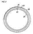
- Each of the gear plates 23 formed of silicon steel has an outer circumferential profile as shown in Fig. 3.
- a concave groove 33 in the axial direction is formed on an outer periphery of the large diameter cylindrical part 25, and convex parts 34 to be engaged with this concave groove 33 are provided on inner peripheries of the respective gear plates 23 formed of silicon steel.
- a plurality of the gear plates 23 formed of silicon steel are aligned in phase so that the respective teeth may come to the same position, and assembled to the large diameter cylindrical part 25 of the annular support member 22, by the engagement between their convex parts 34 and the concave groove 33 of the annular support member 22.
- the pressure ring 24 is assembled to the large diameter cylindrical part 25 of the annular support member 22 by shrinkage fit, whereby drops of the gear plates 23 from the annular support member 22 are prevented.
- Temperature at the shrinkage fit of the pressure ring 24 is 70 to 80°C, forexample.
- an inner diameter of the pressure ring 24 is 100mm for example, an interference is about 100 ⁇ m (an outer diameter of the large diameter part 25 of the annular support member 22 at room temperature is nearly equal to the inner diameter of the pressure ring 24 X 1.001 to 1.0006)
Landscapes
- Physics & Mathematics (AREA)
- General Physics & Mathematics (AREA)
- Transmission And Conversion Of Sensor Element Output (AREA)
- Rolling Contact Bearings (AREA)
Abstract
Description
- The present invention relates to a pulsar ring mounted on an axle of a railway car or the like to constitute a car speed detecting sensor, and a bearing device to which this pulsar ring is attached.
- In
JP-A-7-8771U - In case where the above described pulsar ring in
JP-A-7-8771U - Under the circumstances, an obj ect of the invention is to provide a pulsar ring which can be mounted on a car with reduced troubles, and a bearing device provided with this pulsar ring.
- According to the invention, there is provided a pulsar ring comprising an annular support member having a cylindrical part which is provided, at its one end, with a positioning flange part, a plurality of gear plates formed of silicon steel which are positioned by the positioning flange part and assembled to an outer periphery of the cylindrical part of the annular support member, and a pressure ring which is finally assembled to the outer periphery of the cylindrical part of the annular support member for preventing drops of the gear plates formed of silicon steel, characterized in that a concave groove in an axial direction is formed on the outer periphery of the cylindrical part of the annular support member, and convex parts to be engaged with this concave groove are provided on inner peripheries of the respective gear plates formed of silicon steel.
- According to the invention, there is further provided a bearing device comprising an axle box provided on a car body for supporting an axle, a bearing including an inner ring which is rotated with the axle, an outer ring fixed to the axle box, and a rolling element arranged between both the inner and outer rings, a pulsar ring as a detected part of a car speed detecting sensor which is mounted on the axle, and a detecting coil as a detecting part of the car speed detecting sensor which is mounted on the axle box, the pulsar ring including an annular support member having a cylindrical part which is provided, at its one end, with a positioning flange part, a plurality of gearplates formed of silicon steel which are positioned by the positioning flange part and assembled to an outer periphery of the cylindrical part of the annular support member, and a pressure ring which is finally assembled to the outer periphery of the cylindrical part of the annular support member for preventing drops of the gear plates formed of silicon steel, characterized in that a concave groove in an axial direction is formed on the outer periphery of the cylindrical part of the annular support member of the pulsar ring, and convex parts to be engaged with this concave groove are provided on inner peripheries of the respective gear plates formed of silicon steel.
- The pulsar ring constitutes the detected part of the car speed detecting sensor, by forming teeth at equal intervals on an outer periphery of a ferromagnetic body in a shape of disc having a hole. A loss of eddy current can be decreased by stacking a plurality of gear plates formed of silicon steel. The pulsar ring according to the invention is formed by assembling a plurality of the gear plates formed of silicon steel by loose fit, having the concave groove engaged with the convex parts so as to be aligned in phase, and then, by assembling the pressure ring to the annular support member by shrinkage fit (press-fit). Because a plurality of the gear plates formed of silicon steel are assembled, in this manner, not by shrinkage fit (press-fit) but by engagement between the concave groove and the convex parts, time required for assembling is remarkably reduced. Drops of a plurality of the gear plates formed of silicon steel can be prevented by assembling the pressure ring by shrinkage fit. Generally, an annular lid member constituting a sealing unit is fixed to an end part of the axle, and the annular support member of the pulsar ring is provided with an appropriate mounting part to the lid member, whereby the pulsar ring is fixed to the lid member by means of this mounting part, and accordingly, to the axle.
- The concave groove and the convex part are in a rectangular shape in section, for example, but not limited to this shape.
- The annular support member of the pulsar ring is formed of metal such as steel, and includes a large diameter cylindrical part having an outwardly directed flange part for positioning the gear plates which is provided at the outer end thereof in the axial direction, and supporting a plurality of the gear plates formed of silicon steel, an inwardly directed flange part continued from an inner end in the axial direction of the large diameter cylindrical part, a small diameter cylindrical part continued from an inner diameter of the inwardly directed flange part and extending inward in the axial direction, an outwardly directed flange part for mounting which is continued from an inner end in the axial direction of the small diameter cylindrical part and provided with a bolt insertion hole, and an axially inwardly projecting part provided close to the inner diameter of the outwardly directed flange part for mounting. The outwardly directed flange part for mounting is butted against the lid member from outside in the axial direction, while the axially inwardly projecting part is butted against the lid member from inside in a radial direction, and a bolt which is passed through the bolt insertion hole of the outwardly directed flange part is screwed into a threaded hole in the lid member, whereby the pulsar ring is fixed to the axle.
- According to the pulsar ring and bearing device of this invention, a plurality of the gear plates formed of silicon steel are assembled not by shrinkage fit (press-fit) but by engagement between the concave groove and the convex parts, and hence, a time required for assembling can be remarkably reduced.
-
- Fig. 1 is a longitudinal sectional view of a pulsar ring and a bearing device in an embodiment according to the invention.
- Fig. 2 is an enlarged sectional view of the pulsar ring.
- Fig. 3 is a right side view of an essential part in Fig. 2.
- Now, an embodiment of the invention will be described referring to the drawings.
- Figs. 1 to 3 show an embodiment of a pulsar ring and a bearing device according to the invention. In the following description, "right" and "left" correspond to a right side and a left side in Fig. 1. The right side is an inside of the car, and the left side is an outside of the car.
- The baring device 1 is used for the railway car, and includes an axle box 3 provided on a body of the car, a rolling
bearing 4 for supporting anaxle 2,sealing units bearing 4, apulsar ring 7 as a detected part of a car speed detecting sensor which is mounted on a left end part of theaxle 2, and a detectingcoil 8 as a detecting part of the car speed detecting sensor which is mounted on the axle box 3. - The rolling
bearing 4 is a double row tapered roller bearing, and has aninner ring 11 which is rotated with theaxle 2, an outer ring fixed to the axle box 3,tapered rollers 13 which are arranged in two rows between the inner andouter rings cage 14 for holding thetapered rollers 13 in the respective rows. - The
sealing unit 6 at the right side (inward in an axial direction) includes aseal cover 15 fixed to theouter ring 12, aseal part 16 fixed to theseal cover 15, and alid member 17 which receives theseal part 16 and prevents inward movement of theinner ring 11 in the axial direction. - The
sealing unit 5 at the left side (outward in the axial direction) includes aseal cover 18 fixed to theouter ring 12, aseal part 19 fixed to theseal cover 18, and an annularseal receiving member 20 which receives theseal part 19 and prevents outward movement of theinner ring 11 in the axial direction, and alid member 21 opposed to themembers seal receiving member 20 in the axial direction. - The
pulsar ring 7 includes anannular support member 22, a plurality ofgear plates 23 formed of silicon steel which have been assembled to theannular support member 22, and apressure ring 24 for preventing drops of a plurality of thegear plates 23 formed of silicon steel. - The
annular support member 22 of thepulsar ring 7 includes a large diametercylindrical part 25 which has an outwardly directedflange part 26 for positioning the gear plates at the left end thereof, and supports a plurality of thegear plates 23 formed of silicon steel, an inwardly directedflange part 27 continued from a right end of the large diametercylindrical part 25, a small diametercylindrical part 28 continued from an inner diameter of the inwardly directedflange part 27 and extending to the right, an outwardly directedflange part 29 for mounting which is continued from a right end of the small diametercylindrical part 28 and formed with abolt insertion hole 29a, and a rightward projecting part 30 (an axially inwardlyproj ectingpart) which is provided close to an inner diameter of the outwardly directedflange part 29 for mounting. - The outwardly directed
flangepart 29 formountingof theannular support member 22 is butted against thelid member 21 from the left side, and the rightward projectingpart 30 is butted against thelid member 21 from inside in a radial direction. At the same time, abolt 31 which is passed through thebolt insertion hole 29a of the outwardly directedflange part 29 is screwed into a threaded hole of thelid member 21, whereby thepulsar ring 7 is fixed to the axle (rotation side). - Each of the
gear plates 23 formed of silicon steel has an outer circumferential profile as shown in Fig. 3. - As shown in an enlarged scale in Figs. 2 and 3, a
concave groove 33 in the axial direction is formed on an outer periphery of the large diametercylindrical part 25, andconvex parts 34 to be engaged with thisconcave groove 33 are provided on inner peripheries of therespective gear plates 23 formed of silicon steel. - A plurality of the
gear plates 23 formed of silicon steel are aligned in phase so that the respective teeth may come to the same position, and assembled to the large diametercylindrical part 25 of theannular support member 22, by the engagement between theirconvex parts 34 and theconcave groove 33 of theannular support member 22. After a plurality of thegear plates 23 formed of silicon steel have been assembled, thepressure ring 24 is assembled to the large diametercylindrical part 25 of theannular support member 22 by shrinkage fit, whereby drops of thegear plates 23 from theannular support member 22 are prevented. - Temperature at the shrinkage fit of the
pressure ring 24 is 70 to 80°C, forexample. Provided that an inner diameter of thepressure ring 24 is 100mm for example, an interference is about 100µm (an outer diameter of thelarge diameter part 25 of theannular support member 22 at room temperature is nearly equal to the inner diameter of the pressure ring 24 X 1.001 to 1.0006)
Claims (2)
- A pulsar ring comprising:an annular support member having a cylindrical part which is provided with a positioning flange part at one end thereof;a plurality of gear plates formed of silicon steel which are positioned by the positioning flange part and assembled to an outer periphery of the cylindrical part of the annular support member; anda pressure ring which is finally assembled to the outer periphery of the cylindrical part of the annular support member for preventing drops of a plurality of the gear plates formed of silicon steel,wherein a concave groove in an axial direction is formed on the outer periphery of the cylindrical part of the annular support member, and convex parts to be engaged with this concave groove are provided on inner peripheries of the respective gear plates formed of silicon steel.
- A bearing device comprising:an axle box provided on a car body for supporting an axle;a bearing including an inner ring which is rotated with the axle;an outer ring fixed to the axle box; anda rolling element arranged between both the inner and outer rings, a pulsar ring as a detected part of a car speed detecting sensor which is mounted on the axle, and a detecting coil as a detecting part of the car speed detecting sensor which is mounted on the axle box,said pulsar ring including an annular support member having a cylindrical part which is provided, at its one end, with a positioning flange part, a plurality of gear plates formed of silicon steel which are positioned by the positioning flange part and assembled to an outer periphery of the cylindrical part of the annular support member, and a pressure ring which is finally assembled to the outer periphery of the cylindrical part of the annular support member for preventing drops of a plurality of the gear plates formed of silicon steel, wherein a concave groove in an axial direction is formed on the outer periphery of the cylindrical part of the annular support member of the pulsar ring, and convex parts to be engaged with this concave groove are provided on innerperipheries of the respective gear plates formed of silicon steel.
Applications Claiming Priority (1)
| Application Number | Priority Date | Filing Date | Title |
|---|---|---|---|
| JP2006250223A JP2008070276A (en) | 2006-09-15 | 2006-09-15 | Pulsar ring and bearing device |
Publications (2)
| Publication Number | Publication Date |
|---|---|
| EP1901077A2 true EP1901077A2 (en) | 2008-03-19 |
| EP1901077A3 EP1901077A3 (en) | 2009-11-04 |
Family
ID=38861642
Family Applications (1)
| Application Number | Title | Priority Date | Filing Date |
|---|---|---|---|
| EP07018008A Withdrawn EP1901077A3 (en) | 2006-09-15 | 2007-09-13 | Pulsar ring and bearing device |
Country Status (3)
| Country | Link |
|---|---|
| US (1) | US20080074105A1 (en) |
| EP (1) | EP1901077A3 (en) |
| JP (1) | JP2008070276A (en) |
Families Citing this family (1)
| Publication number | Priority date | Publication date | Assignee | Title |
|---|---|---|---|---|
| US8833340B2 (en) | 2011-06-23 | 2014-09-16 | Honda Motor Co., Ltd. | Floating engine timing plate |
Family Cites Families (9)
| Publication number | Priority date | Publication date | Assignee | Title |
|---|---|---|---|---|
| US4461994A (en) * | 1982-03-19 | 1984-07-24 | Litton Industrial Products, Inc. | Permanent magnet inductor tachometer |
| JPH078771U (en) * | 1993-07-13 | 1995-02-07 | エヌティエヌ株式会社 | Pulsar ring |
| US5614822A (en) * | 1994-01-28 | 1997-03-25 | Nsk Ltd. | Rolling bearing unit with rotational speed detection device having a tone wheel and a sensor |
| JPH09281128A (en) * | 1996-04-09 | 1997-10-31 | Toyota Motor Corp | Rotating body |
| JP2000074934A (en) * | 1998-09-01 | 2000-03-14 | Tamagawa Seiki Co Ltd | Rotating body for speed sensor |
| JP2002295500A (en) * | 2001-03-29 | 2002-10-09 | Aisin Aw Co Ltd | Detent device |
| JP4296486B2 (en) * | 2003-08-18 | 2009-07-15 | 株式会社ジェイテクト | Variable reluctance resolver |
| JP4293058B2 (en) * | 2004-06-02 | 2009-07-08 | 日本精工株式会社 | Rotation speed detector |
| JP2006158005A (en) * | 2004-11-25 | 2006-06-15 | Toyota Motor Corp | Resolver rotor fixing structure |
-
2006
- 2006-09-15 JP JP2006250223A patent/JP2008070276A/en active Pending
-
2007
- 2007-09-13 US US11/898,586 patent/US20080074105A1/en not_active Abandoned
- 2007-09-13 EP EP07018008A patent/EP1901077A3/en not_active Withdrawn
Also Published As
| Publication number | Publication date |
|---|---|
| EP1901077A3 (en) | 2009-11-04 |
| US20080074105A1 (en) | 2008-03-27 |
| JP2008070276A (en) | 2008-03-27 |
Similar Documents
| Publication | Publication Date | Title |
|---|---|---|
| JP6253877B2 (en) | Cylindrical roller bearing | |
| US10655672B2 (en) | Method and device for producing an angular contact roller bearing | |
| US6102579A (en) | Cage or set of rollers for roller bearings | |
| US20190063501A1 (en) | Cross roller bearing | |
| CN207634514U (en) | Wheel support roller bearing unit | |
| US20150316103A1 (en) | Rolling bearing | |
| US10598226B2 (en) | Bearing device for vehicle wheel | |
| JP2001010304A (en) | Hub unit for supporting wheels and method of assembling the same | |
| US20080074105A1 (en) | Pulsar ring and bearing device | |
| CN101278135A (en) | Roller bearing | |
| JP5336317B2 (en) | Tapered roller bearing | |
| EP1630433A2 (en) | Rolling bearing unit | |
| JP3757309B2 (en) | Pinion shaft support bearing unit | |
| JP2005140157A (en) | Rolling bearing | |
| US20160017922A1 (en) | Rolling bearing comprising a housing having two parts and method for manufacturing and installing such a bearing | |
| JP4244955B2 (en) | Assembly method for automotive hub unit | |
| US20070025654A1 (en) | Tapered roller bearing assembly and method of fabricating the same | |
| JP7007924B2 (en) | Bearing equipment for wheels | |
| US1300590A (en) | Roller-bearing applicable to gravity-runways or other purposes. | |
| EP3548760B1 (en) | Bearing assembly and bearing cage | |
| TWI655374B (en) | Radial roller bearing | |
| JP2008051725A (en) | Pulsar ring and bearing device | |
| JP2006275200A (en) | Cover for rolling bearing device and rolling bearing device using the same | |
| JP2020060223A (en) | Hub unit bearing | |
| JP2005280567A (en) | Bearing device for wheel |
Legal Events
| Date | Code | Title | Description |
|---|---|---|---|
| PUAI | Public reference made under article 153(3) epc to a published international application that has entered the european phase |
Free format text: ORIGINAL CODE: 0009012 |
|
| AK | Designated contracting states |
Kind code of ref document: A2 Designated state(s): AT BE BG CH CY CZ DE DK EE ES FI FR GB GR HU IE IS IT LI LT LU LV MC MT NL PL PT RO SE SI SK TR |
|
| AX | Request for extension of the european patent |
Extension state: AL BA HR MK YU |
|
| PUAL | Search report despatched |
Free format text: ORIGINAL CODE: 0009013 |
|
| AK | Designated contracting states |
Kind code of ref document: A3 Designated state(s): AT BE BG CH CY CZ DE DK EE ES FI FR GB GR HU IE IS IT LI LT LU LV MC MT NL PL PT RO SE SI SK TR |
|
| AX | Request for extension of the european patent |
Extension state: AL BA HR MK RS |
|
| AKX | Designation fees paid | ||
| STAA | Information on the status of an ep patent application or granted ep patent |
Free format text: STATUS: THE APPLICATION IS DEEMED TO BE WITHDRAWN |
|
| 18D | Application deemed to be withdrawn |
Effective date: 20100505 |
|
| REG | Reference to a national code |
Ref country code: DE Ref legal event code: 8566 |