EP1900646A1 - Method and system for protecting privacy of signature on mail ballot utilizing optical shutter - Google Patents
Method and system for protecting privacy of signature on mail ballot utilizing optical shutter Download PDFInfo
- Publication number
- EP1900646A1 EP1900646A1 EP07016811A EP07016811A EP1900646A1 EP 1900646 A1 EP1900646 A1 EP 1900646A1 EP 07016811 A EP07016811 A EP 07016811A EP 07016811 A EP07016811 A EP 07016811A EP 1900646 A1 EP1900646 A1 EP 1900646A1
- Authority
- EP
- European Patent Office
- Prior art keywords
- envelope
- optical shutter
- information
- state
- signature
- Prior art date
- Legal status (The legal status is an assumption and is not a legal conclusion. Google has not performed a legal analysis and makes no representation as to the accuracy of the status listed.)
- Granted
Links
- 230000003287 optical effect Effects 0.000 title claims abstract description 64
- 238000000034 method Methods 0.000 title claims abstract description 15
- 238000012545 processing Methods 0.000 claims description 7
- 238000009877 rendering Methods 0.000 abstract description 4
- 230000003068 static effect Effects 0.000 abstract description 2
- 239000000758 substrate Substances 0.000 description 17
- 239000004988 Nematic liquid crystal Substances 0.000 description 9
- 238000010586 diagram Methods 0.000 description 4
- 239000004973 liquid crystal related substance Substances 0.000 description 4
- AMGQUBHHOARCQH-UHFFFAOYSA-N indium;oxotin Chemical compound [In].[Sn]=O AMGQUBHHOARCQH-UHFFFAOYSA-N 0.000 description 2
- 238000002360 preparation method Methods 0.000 description 2
- 238000007789 sealing Methods 0.000 description 2
- 238000012795 verification Methods 0.000 description 2
- 238000007792 addition Methods 0.000 description 1
- 239000000853 adhesive Substances 0.000 description 1
- 230000001070 adhesive effect Effects 0.000 description 1
- 238000004891 communication Methods 0.000 description 1
- 238000012217 deletion Methods 0.000 description 1
- 230000037430 deletion Effects 0.000 description 1
- 238000005516 engineering process Methods 0.000 description 1
- 239000011521 glass Substances 0.000 description 1
- 239000003292 glue Substances 0.000 description 1
- 238000003384 imaging method Methods 0.000 description 1
- 238000011835 investigation Methods 0.000 description 1
- 239000000463 material Substances 0.000 description 1
- 238000012986 modification Methods 0.000 description 1
- 230000004048 modification Effects 0.000 description 1
- 238000006467 substitution reaction Methods 0.000 description 1
Images


Classifications
-
- B—PERFORMING OPERATIONS; TRANSPORTING
- B65—CONVEYING; PACKING; STORING; HANDLING THIN OR FILAMENTARY MATERIAL
- B65D—CONTAINERS FOR STORAGE OR TRANSPORT OF ARTICLES OR MATERIALS, e.g. BAGS, BARRELS, BOTTLES, BOXES, CANS, CARTONS, CRATES, DRUMS, JARS, TANKS, HOPPERS, FORWARDING CONTAINERS; ACCESSORIES, CLOSURES, OR FITTINGS THEREFOR; PACKAGING ELEMENTS; PACKAGES
- B65D27/00—Envelopes or like essentially-rectangular flexible containers for postal or other purposes having no structural provision for thickness of contents
- B65D27/04—Envelopes or like essentially-rectangular flexible containers for postal or other purposes having no structural provision for thickness of contents with apertures or windows for viewing contents
-
- B—PERFORMING OPERATIONS; TRANSPORTING
- B65—CONVEYING; PACKING; STORING; HANDLING THIN OR FILAMENTARY MATERIAL
- B65D—CONTAINERS FOR STORAGE OR TRANSPORT OF ARTICLES OR MATERIALS, e.g. BAGS, BARRELS, BOTTLES, BOXES, CANS, CARTONS, CRATES, DRUMS, JARS, TANKS, HOPPERS, FORWARDING CONTAINERS; ACCESSORIES, CLOSURES, OR FITTINGS THEREFOR; PACKAGING ELEMENTS; PACKAGES
- B65D27/00—Envelopes or like essentially-rectangular flexible containers for postal or other purposes having no structural provision for thickness of contents
Definitions
- the invention disclosed herein relates generally to voting systems, and more particularly to a method and system for protecting privacy of signatures on ballots sent through the mail.
- governmental officials are chosen by the citizens in an election. Conducting an election and voting for candidates for public office in the United States can be performed in several different ways.
- One such way utilizes mechanical voting machines at predetermined polling places. When potential voters enter the predetermined polling place, voting personnel verify that each voter is properly registered in that voting district and that they have not already voted in that election. Thus, for a voter to cast his vote, he must go to the polling place at which he is registered, based on the voter's residence.
- Another method for conducting an election and voting utilizes paper ballots that are mailed to the voter who marks the ballot and returns the ballot through the mail. Mailed ballots have been historically reserved for absentee voting.
- the voter marks the ballot to cast his/her vote and then inserts the ballot in a return envelope which is typically pre-addressed to the voter registrar office in the corresponding county, town or locality in which the voter is registered.
- the voter typically appends his/her signature on the back of the envelope adjacent his/her human or machine readable identification.
- a voting official compares the voter signature on the envelope with the voter signature retrieved from the registration file to make a determination as to whether or not the identification information and signature are authentic and valid, and therefore the vote included in the envelope should be counted. If the identification information and signature are deemed to be authentic and valid, the identifying information and signature are separated from the sealed ballot before it is handed to the ballot counters for tabulation. In this manner, the privacy of the voter's selections is maintained and thus the ballot remains a "secret ballot.”
- Voting by mail is becoming more prevalent, apart from the usual absentee voting, and in some jurisdictions, entire elections are being conducted exclusively by mail. As the voting by mail becomes more prevalent, the privacy concerns are also more prevalent. Thus, there exists a need for efficient methods and systems that can protect the privacy of signatures on ballots sent through the mail while also reducing the risk of damage to the ballots when the signatures are revealed.
- the present invention alleviates the problems associated with the prior art and provides methods and systems that protect the privacy of signatures on ballots sent through the mail while also reducing the risk of damage to the ballots when the signatures are revealed.
- the envelope for returning ballots by mail includes an electronic optical shutter that covers an opening in the flap of the envelope.
- the voter signs the back of the envelope in an area that will be visible through the opening in the flap (covered by the optical shutter) when the envelope flap is sealed.
- the optical shutter is opaque under static conditions, but will become transparent when appropriate power is supplied to it.
- the optical shutter can be powered, thereby rendering the optical shutter transparent, and the voter's signature can be viewed for comparison with the official records to perform the required signature verification to determine validity and authenticity of the ballot.
- the envelope flap is provided with conductive power rails that will allow power to be supplied to the optical shutter while the envelope is being processed by automated mail processing equipment.
- the voter's signature will be concealed from plain view. Viewing of the signature does not require any mechanical manipulation of the envelope or flaps on the envelope, thereby reducing the processing cost and the risk of causing damage to the ballot contained therein.
- the ballot can be separated from the envelope and provided to the ballot counters for tabulation.
- the optical shutter can be reused on subsequent envelopes.
- FIG. 1 illustrates an envelope for returning ballots by mail according to an embodiment of the present invention in an open position
- FIG. 2 illustrates the envelope of Fig. 1 in a closed position
- FIG. 3 illustrates in schematic form an optical shutter and conductive rails according to an embodiment of the present invention
- FIG. 4 illustrates in block diagram form a system for viewing the signature concealed using the envelope illustrated in Figs. 1 and 2 according to an embodiment of the present invention
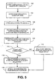
- FIG. 5 illustrates in flow diagram form the preparation and processing of an envelope for mailing a ballot according to an embodiment of the present invention.
- FIG. 1 an envelope 10 for returning ballots by mail according to an embodiment of the present invention in an open position. While the present description is directed to an envelope for returning ballots by mail, it should be understood that the invention is not so limited and the envelope 10 could be used to hold any type of communication or material.
- Envelope 10 includes a body portion 12 and a flap portion 14 connected to the body portion 12. When the flap portion 14 is in an open position as illustrated in Fig. 1, contents, such as, for example, a ballot, can be inserted into a pocket 18 formed by the body portion 12. The flap portion 14 can then be moved to a closed position (as illustrated in Fig. 2), and sealed utilizing a glue or sealing strip 16 which when activated will adhere the flap portion 14 to the body portion 12, thereby covering the pocket 18 and preventing the contents therein from falling out.
- a glue or sealing strip 16 which when activated will adhere the flap portion 14 to the body portion 12, thereby covering the pocket 18 and preventing the contents therein from falling out.
- the body portion 12 is provided with an area 20 intended for the voter's signature along with an area 22 in which information that identifies the voter is provided.
- information can include, for example, the voter's name and address, and is preferably provided in some machine readable form such as a barcode.
- the identification information is preferably preprinted on the body portion 12 of the envelope 10, or alternatively may be preprinted on an adhesive label that the voter applies to the body portion 12 in the area 22.
- the flap portion includes an opening 30 (indicated by the dashed lines in Fig. 1) that corresponds with the areas 20, 22 of the body portion when the flap portion 14 is in the closed position.
- An optical shutter 32 is placed such that the optical shutter 32 covers the opening 30.
- the optical shutter 32 covers the areas 20, 22 on the body portion 12 of the envelope 10. Since the sealing strip 16 preferably extends along the sides of the flap portion 14, access to the areas 20, 22 is prevented through the side of the flap portion 14.
- the optical shutter 32 has two states, transparent and opaque. When the optical shutter 32 is opaque, it will conceal the information contained in the areas 20, 22 on the body portion 12 of the envelope 10.
- optical shutter 32 When the optical shutter 32 is transparent, the information contained in the areas 20, 22 of the body portion 12 is not concealed and can be read (through the opening 30 and optical shutter 32).
- An example of an optical shutter 32 is a liquid crystal display shutter, such as is available from Liquid Crystal Technologies, Cleveland, Ohio.
- the state of the optical shutter 32 is changed by applying voltage to the optical shutter 32, preferably through a pair of conductive traces, such as, for example, conductive rails 40, 42, as described below.
- Fig. 3 illustrates in schematic form an optical shutter 32 in the form of a liquid crystal display and conductive rails 40, 42 according to an embodiment of the present invention. While the structure and operation of a liquid crystal display is well known in the art and need not be described in detail for an understanding of the present invention, a general description of the structure and operation will be provided.
- Optical shutter 32 includes a layer of nematic liquid crystals 52 sandwiched between two clear polarized substrates 44, 46, such as, for example, glass that has a polarizing film applied to the side facing outward away from the layer 52, oriented such that the polarizing films are in the same direction.
- the side of the substrate 44 that does not have the polarizing film (facing toward the layer 52) has microscopic grooves in the surface that are oriented at a ninety degree angle to the polarizing film.
- the side of the substrate 46 that does not have the polarizing film (facing toward the layer 52) has microscopic grooves in the surface that are in the same direction as the polarizing film.
- a common electrode plane 48 formed from, for example, indium-tin oxide, is provided on the side of the substrate 44 with the grooves. Common electrode plane 48 is connected to a first conductive rail 42.
- a segment electrode plane 50 which can also be formed, for example, from indium-tin oxide, is provided on the side of the substrate 46 with the grooves.
- Segment electrode plane 50 is connected to a second conductive rail 40 (described further below).
- the molecules of the first layer of nematic liquid crystals 52 closest to the substrate 44 will align with the groves in the substrate 44, thereby aligning at a ninety degree angle to the polarizing, orientation of the substrate 44.
- Each successive layer of molecules of the nematic liquid crystals 52 will gradually twist until the uppermost layer closest to the substrate 46 is at a ninety-degree angle to the bottom layer, thereby matching the polarizing orientation of the substrate 46.
- the first substrate 46 As light traveling in the direction indicated by the arrow 56 strikes the first substrate 46, it is polarized in the polarizing orientation of the substrate 46 and passed through.
- the molecules in each layer of the nematic liquid crystals 52 guide the light to each successive layer. As light passes through each molecule, the orientation of the light is changed to match the plane of each molecule. When the light reaches the final layer of molecules in the nematic liquid crystals 52, its orientation is at the same angle as the final layer of molecules, which is at a ninety degree angle to the polarizing orientation of the substrate 44. As such, the light will not pass through the substrate 44 and the optical shutter 32 will appear as a dark area, i.e., opaque.
- the nematic liquid crystals 52 When a voltage is applied between the common electrode plane 48 and the segment electrode plane 50, thereby passing a current through the nematic liquid crystals 52, the nematic liquid crystals 52 will untwist. The untwisting of the nematic liquid crystals 52 will change the angle of the light passing through them, aligning the orientation of the light to match the polarizing orientation of the substrate 44. As such, with a voltage applied to the planes 48, 50, light will pass through the substrate 44 and the optical shutter 32 will appear transparent.
- Fig. 4 illustrates in block diagram form an automated system 60 for viewing the signature concealed using an optical shutter 32 and envelope 10 illustrated in Figs. 1-3 according to an embodiment of the present invention.
- System 60 includes a control unit 62, such as, for example, a general or special purpose microprocessor or the like, that controls operation of the system 60.
- Control unit 62 is connected to a database 74, which is used to store voter information, including, for example, name, address, and a reference signature for use in verifying ballots received by mail as described below.
- a transport 64 such as, for example, rollers and/or belts, is used to transport a series of envelopes 10 (only one shown in Fig. 4) through the system 60. The speed of the transport 64 is preferably controlled by the control unit 62.
- a reading device 66 such as, for example, a scanner, camera, or the like is positioned adjacent to the transport 64 such that information provided on envelopes 10 being transported past the reading device 66 can be read therefrom.
- a diverter 76 is located downstream from the reading device 66 and is coupled to the control unit 62. Based on command signals from the control unit 62, the diverter 76 will divert each envelope to a reject path 78 or an accept ballot path 80 as described below.
- the system 60 will apply a voltage from voltage supply source 68 to the optical shutter 32 of each envelope being transported therethrough, thereby rendering the optical shutter 32 transparent and allowing the reading device 66 to read each voter's signature located under the optical shutter 32.
- the voltage applied between the common electrode plane 48 and segment electrode plane 50 is preferably an AC RMS voltage with a minimal (approximately 50 mv or less) DC offset, as a DC voltage will cause damage to the nematic liquid crystals 52 which will eventually destroy them.
- the voltage source 68 may be an AC voltage source and the rails 40, 42 may be continuous rails. It is preferable to apply a square wave voltage signal to the common plane 48 and segment plane 50.
- the voltage supply 68 is a DC voltage source, that, coupled with the alternating contacts 54 of the conductive rail 40 (see Fig. 3), will result in the application of an AC square wave to the optical shutter 32.
- Voltage supply 68 is coupled to a pair of contacts 72a, 72b which are secured by a contact holder 70.
- the contacts 72a, 72b are preferably finger like projections that extend into the path of travel of the envelopes 10.
- the contacts 72a, 72b preferably include a biasing means, such as, for example, a spring or the like (not shown), to bias them towards the transport 64, thereby ensuring suitable contact between the contacts 72a, 72b and an envelope 10 passing underneath.
- Each contact 72a, 72b aligns with a respective conductive rail 40, 42 such that as the envelope 10 passes beneath the contact holder 70, the contacts 72a, 72b make a conductive connection to the conductive rails 40, 42 and allow voltage from the voltage supply 68 to be applied to the conductive rails 40, 42.
- the length of the alternating pattern of contacts 54, the space between each contact 54, and the speed of the transport 64 can be used to control the drive frequency of the square wave applied to each optical shutter 32.
- the drive frequency is in the range of 40 to 60 Hz.
- Fig. 5 illustrates in flow diagram form the preparation and processing of an envelope 10 for mailing a ballot according to an embodiment of the present invention.
- a voter completes a ballot and inserts it into the pocket 18 of envelope 10.
- the voter signs the envelope 10 in the signature area 20.
- the voter seals the flap portion 14 to the body portion 12 of the envelope 10, thereby covering the identification area 22 and signature area 20 with the optical shutter 32, and mails the envelope 10 to the registrar's office. Since the optical shutter 32 is not provided with any power, it will appear opaque, as described above, and the signature and identification located in the areas 22 and 20 will be hidden from view. Thus, the privacy of the voter's signature is maintained during transit of the envelope 10 from the voter to the registrar's office.
- step 106 Upon receipt of the envelope 10 at the registrar's office, in step 106 the envelope 10 is processed using the system as illustrated in Fig. 4.
- the envelope 10 is transported by the transport 64 and a voltage is applied to the conductive rails 40, 42 via the contacts 72a, 72b, thereby rendering the optical shutter 32 transparent as described above.
- the reading device 66 can then read the identification information in area 22 and the signature in area 20 from the envelope 10.
- the control unit 62 will retrieve the reference signature from the database 74, based on the identification of the voter in area 22, and compare the reference signature to the signature read from area 20 of envelope 10.
- step 110 it is determined if the reference signature retrieved from the data base 74 corresponds to the signature read from area 20 of envelope 10.
- step 112 the ballot is rejected as not being verified and the envelope 10 is diverted by the diverter 76 to the reject path 78. Envelopes diverted to the reject path may be subject to some type of investigation to make a final determination if the vote should be counted or not. If in step 110 it is determined that the signatures do correspond, then in step 114 the ballot is deemed to be authentic and verified and the envelope 10 is diverted by the diverter 76 to the accept ballot path 80, in which the ballot will be given to ballot counters for tabulation.
- the ballot is removed from the envelope 10 before being given to the ballot counters thereby maintaining a "secret ballot.”
- the optical shutter 32 is removed from the envelope 10 (regardless of whether the vote was counted in step 114 or not counted in step 112) for reuse in subsequent elections.
Landscapes
- Engineering & Computer Science (AREA)
- Mechanical Engineering (AREA)
- Credit Cards Or The Like (AREA)
Abstract
Description
- The invention disclosed herein relates generally to voting systems, and more particularly to a method and system for protecting privacy of signatures on ballots sent through the mail.
- In democratic countries, governmental officials are chosen by the citizens in an election. Conducting an election and voting for candidates for public office in the United States can be performed in several different ways. One such way utilizes mechanical voting machines at predetermined polling places. When potential voters enter the predetermined polling place, voting personnel verify that each voter is properly registered in that voting district and that they have not already voted in that election. Thus, for a voter to cast his vote, he must go to the polling place at which he is registered, based on the voter's residence. Another method for conducting an election and voting utilizes paper ballots that are mailed to the voter who marks the ballot and returns the ballot through the mail. Mailed ballots have been historically reserved for absentee voting. In the usual absentee voting process, the voter marks the ballot to cast his/her vote and then inserts the ballot in a return envelope which is typically pre-addressed to the voter registrar office in the corresponding county, town or locality in which the voter is registered. The voter typically appends his/her signature on the back of the envelope adjacent his/her human or machine readable identification.
- When the return envelope is received at the registrar's office, a voting official compares the voter signature on the envelope with the voter signature retrieved from the registration file to make a determination as to whether or not the identification information and signature are authentic and valid, and therefore the vote included in the envelope should be counted. If the identification information and signature are deemed to be authentic and valid, the identifying information and signature are separated from the sealed ballot before it is handed to the ballot counters for tabulation. In this manner, the privacy of the voter's selections is maintained and thus the ballot remains a "secret ballot."
- One general problem with vote by mail envelopes is the signature is in the open and exposed for all to see throughout the process for determining whether or not the vote is authentic. This leads to potential privacy issues and concerns, e.g., fraudulent usage of a voter's signature. Some jurisdictions have required that such signatures be hidden from plain sight while the envelope is en route from the voter to the registrar's office. This will protect against easy imaging of the signature, such as, for example, with a hand scanner or digital camera, for later impersonation or other fraudulent purposes, e.g., identity theft. To comply with such requirements, envelopes have been proposed that hide the signature with a flap which is removed when the envelope is received at the registrar's office. These solutions, however, require some mechanical manipulation of the envelopes, which is both expensive and increases the risk of accidental tears of the envelope, potentially leading to damage to the ballots contained in the envelopes and subsequently errors in the counting of votes.
- Voting by mail is becoming more prevalent, apart from the usual absentee voting, and in some jurisdictions, entire elections are being conducted exclusively by mail. As the voting by mail becomes more prevalent, the privacy concerns are also more prevalent. Thus, there exists a need for efficient methods and systems that can protect the privacy of signatures on ballots sent through the mail while also reducing the risk of damage to the ballots when the signatures are revealed.
- The present invention alleviates the problems associated with the prior art and provides methods and systems that protect the privacy of signatures on ballots sent through the mail while also reducing the risk of damage to the ballots when the signatures are revealed.
- In accordance with the present invention, the envelope for returning ballots by mail includes an electronic optical shutter that covers an opening in the flap of the envelope. The voter signs the back of the envelope in an area that will be visible through the opening in the flap (covered by the optical shutter) when the envelope flap is sealed. The optical shutter is opaque under static conditions, but will become transparent when appropriate power is supplied to it. Thus, when the envelope flap is sealed and no power is applied to the optical shutter, the voter's signature will be concealed by the optical shutter. Upon receipt at the registrar's office (or other official vote tallying location), the optical shutter can be powered, thereby rendering the optical shutter transparent, and the voter's signature can be viewed for comparison with the official records to perform the required signature verification to determine validity and authenticity of the ballot. Preferably, the envelope flap is provided with conductive power rails that will allow power to be supplied to the optical shutter while the envelope is being processed by automated mail processing equipment. Thus, while the envelope is en route from the voter to the registrar's office, the voter's signature will be concealed from plain view. Viewing of the signature does not require any mechanical manipulation of the envelope or flaps on the envelope, thereby reducing the processing cost and the risk of causing damage to the ballot contained therein. After verification of the voter's signature, the ballot can be separated from the envelope and provided to the ballot counters for tabulation. Optionally, the optical shutter can be reused on subsequent envelopes.
- Therefore, it should now be apparent that the invention substantially achieves all the above aspects and advantages. Additional aspects and advantages of the invention will be set forth in the description that follows, and in part will be obvious from the description, or may be learned by practice of the invention. Moreover, the aspects and advantages of the invention may be realized and obtained by means of the instrumentalities and combinations particularly pointed out in the appended claims.
- The accompanying drawings illustrate presently preferred embodiments of the invention, and together with the general description given above and the detailed description given below, serve to explain the principles of the invention. As shown throughout the drawings, like reference numerals designate like or corresponding parts.
- FIG. 1 illustrates an envelope for returning ballots by mail according to an embodiment of the present invention in an open position;
- FIG. 2 illustrates the envelope of Fig. 1 in a closed position;
- FIG. 3 illustrates in schematic form an optical shutter and conductive rails according to an embodiment of the present invention;
- FIG. 4 illustrates in block diagram form a system for viewing the signature concealed using the envelope illustrated in Figs. 1 and 2 according to an embodiment of the present invention; and
- FIG. 5 illustrates in flow diagram form the preparation and processing of an envelope for mailing a ballot according to an embodiment of the present invention.
- In describing the present invention, reference is made to the drawings, wherein there is seen in Fig. 1 an
envelope 10 for returning ballots by mail according to an embodiment of the present invention in an open position. While the present description is directed to an envelope for returning ballots by mail, it should be understood that the invention is not so limited and theenvelope 10 could be used to hold any type of communication or material.Envelope 10 includes abody portion 12 and aflap portion 14 connected to thebody portion 12. When theflap portion 14 is in an open position as illustrated in Fig. 1, contents, such as, for example, a ballot, can be inserted into apocket 18 formed by thebody portion 12. Theflap portion 14 can then be moved to a closed position (as illustrated in Fig. 2), and sealed utilizing a glue orsealing strip 16 which when activated will adhere theflap portion 14 to thebody portion 12, thereby covering thepocket 18 and preventing the contents therein from falling out. - The
body portion 12 is provided with anarea 20 intended for the voter's signature along with anarea 22 in which information that identifies the voter is provided. Such information can include, for example, the voter's name and address, and is preferably provided in some machine readable form such as a barcode. The identification information is preferably preprinted on thebody portion 12 of theenvelope 10, or alternatively may be preprinted on an adhesive label that the voter applies to thebody portion 12 in thearea 22. - The flap portion includes an opening 30 (indicated by the dashed lines in Fig. 1) that corresponds with the
areas flap portion 14 is in the closed position. Anoptical shutter 32 is placed such that theoptical shutter 32 covers theopening 30. As shown in Fig. 2, when theflap portion 14 is folded over thebody portion 12, theoptical shutter 32 covers theareas body portion 12 of theenvelope 10. Since thesealing strip 16 preferably extends along the sides of theflap portion 14, access to theareas flap portion 14. Theoptical shutter 32 has two states, transparent and opaque. When theoptical shutter 32 is opaque, it will conceal the information contained in theareas body portion 12 of theenvelope 10. When theoptical shutter 32 is transparent, the information contained in theareas body portion 12 is not concealed and can be read (through the opening 30 and optical shutter 32). An example of anoptical shutter 32 is a liquid crystal display shutter, such as is available from Liquid Crystal Technologies, Cleveland, Ohio. The state of theoptical shutter 32 is changed by applying voltage to theoptical shutter 32, preferably through a pair of conductive traces, such as, for example,conductive rails - Fig. 3 illustrates in schematic form an
optical shutter 32 in the form of a liquid crystal display andconductive rails Optical shutter 32 includes a layer of nematicliquid crystals 52 sandwiched between two clear polarizedsubstrates layer 52, oriented such that the polarizing films are in the same direction. The side of thesubstrate 44 that does not have the polarizing film (facing toward the layer 52) has microscopic grooves in the surface that are oriented at a ninety degree angle to the polarizing film. The side of thesubstrate 46 that does not have the polarizing film (facing toward the layer 52) has microscopic grooves in the surface that are in the same direction as the polarizing film. Acommon electrode plane 48, formed from, for example, indium-tin oxide, is provided on the side of thesubstrate 44 with the grooves.Common electrode plane 48 is connected to a firstconductive rail 42. Asegment electrode plane 50, which can also be formed, for example, from indium-tin oxide, is provided on the side of thesubstrate 46 with the grooves.Segment electrode plane 50 is connected to a second conductive rail 40 (described further below). The molecules of the first layer of nematicliquid crystals 52 closest to thesubstrate 44 will align with the groves in thesubstrate 44, thereby aligning at a ninety degree angle to the polarizing, orientation of thesubstrate 44. Each successive layer of molecules of the nematicliquid crystals 52 will gradually twist until the uppermost layer closest to thesubstrate 46 is at a ninety-degree angle to the bottom layer, thereby matching the polarizing orientation of thesubstrate 46. - As light traveling in the direction indicated by the
arrow 56 strikes thefirst substrate 46, it is polarized in the polarizing orientation of thesubstrate 46 and passed through. The molecules in each layer of the nematicliquid crystals 52 guide the light to each successive layer. As light passes through each molecule, the orientation of the light is changed to match the plane of each molecule. When the light reaches the final layer of molecules in the nematicliquid crystals 52, its orientation is at the same angle as the final layer of molecules, which is at a ninety degree angle to the polarizing orientation of thesubstrate 44. As such, the light will not pass through thesubstrate 44 and theoptical shutter 32 will appear as a dark area, i.e., opaque. When a voltage is applied between thecommon electrode plane 48 and thesegment electrode plane 50, thereby passing a current through the nematicliquid crystals 52, the nematicliquid crystals 52 will untwist. The untwisting of the nematicliquid crystals 52 will change the angle of the light passing through them, aligning the orientation of the light to match the polarizing orientation of thesubstrate 44. As such, with a voltage applied to theplanes substrate 44 and theoptical shutter 32 will appear transparent. - The use of the
conductive rails optical shutter 32. Theconductive rails optical shutter 32 as theenvelope 10 is being processed by automated processing equipment. Theconductive rails substrate 46 or to thebody portion 12 with connections to theapplicable plane conductive rail 40 is preferably provided with alternatingcontacts 54, the reason for which described below. Fig. 4 illustrates in block diagram form anautomated system 60 for viewing the signature concealed using anoptical shutter 32 andenvelope 10 illustrated in Figs. 1-3 according to an embodiment of the present invention.System 60 includes acontrol unit 62, such as, for example, a general or special purpose microprocessor or the like, that controls operation of thesystem 60.Control unit 62 is connected to adatabase 74, which is used to store voter information, including, for example, name, address, and a reference signature for use in verifying ballots received by mail as described below. Atransport 64, such as, for example, rollers and/or belts, is used to transport a series of envelopes 10 (only one shown in Fig. 4) through thesystem 60. The speed of thetransport 64 is preferably controlled by thecontrol unit 62. Areading device 66, such as, for example, a scanner, camera, or the like is positioned adjacent to thetransport 64 such that information provided onenvelopes 10 being transported past thereading device 66 can be read therefrom. Adiverter 76 is located downstream from thereading device 66 and is coupled to thecontrol unit 62. Based on command signals from thecontrol unit 62, thediverter 76 will divert each envelope to areject path 78 or an acceptballot path 80 as described below. - The
system 60 will apply a voltage fromvoltage supply source 68 to theoptical shutter 32 of each envelope being transported therethrough, thereby rendering theoptical shutter 32 transparent and allowing thereading device 66 to read each voter's signature located under theoptical shutter 32. The voltage applied between thecommon electrode plane 48 andsegment electrode plane 50 is preferably an AC RMS voltage with a minimal (approximately 50 mv or less) DC offset, as a DC voltage will cause damage to the nematicliquid crystals 52 which will eventually destroy them. Thus, thevoltage source 68 may be an AC voltage source and therails common plane 48 andsegment plane 50. While a purely AC signal (with no DC offset) can easily be generated, it is preferable for thevoltage supply 68 to be a DC voltage source, that, coupled with the alternatingcontacts 54 of the conductive rail 40 (see Fig. 3), will result in the application of an AC square wave to theoptical shutter 32.Voltage supply 68 is coupled to a pair ofcontacts contact holder 70. Thecontacts envelopes 10. Thecontacts transport 64, thereby ensuring suitable contact between thecontacts envelope 10 passing underneath. Eachcontact conductive rail envelope 10 passes beneath thecontact holder 70, thecontacts conductive rails voltage supply 68 to be applied to theconductive rails contacts 54, the space between eachcontact 54, and the speed of thetransport 64 can be used to control the drive frequency of the square wave applied to eachoptical shutter 32. Preferably, the drive frequency is in the range of 40 to 60 Hz. - Fig. 5 illustrates in flow diagram form the preparation and processing of an
envelope 10 for mailing a ballot according to an embodiment of the present invention. Instep 100, a voter completes a ballot and inserts it into thepocket 18 ofenvelope 10. Instep 102, the voter signs theenvelope 10 in thesignature area 20. Instep 104, the voter seals theflap portion 14 to thebody portion 12 of theenvelope 10, thereby covering theidentification area 22 andsignature area 20 with theoptical shutter 32, and mails theenvelope 10 to the registrar's office. Since theoptical shutter 32 is not provided with any power, it will appear opaque, as described above, and the signature and identification located in theareas envelope 10 from the voter to the registrar's office. - Upon receipt of the
envelope 10 at the registrar's office, instep 106 theenvelope 10 is processed using the system as illustrated in Fig. 4. Theenvelope 10 is transported by thetransport 64 and a voltage is applied to theconductive rails contacts optical shutter 32 transparent as described above. Thereading device 66 can then read the identification information inarea 22 and the signature inarea 20 from theenvelope 10. Instep 108, thecontrol unit 62 will retrieve the reference signature from thedatabase 74, based on the identification of the voter inarea 22, and compare the reference signature to the signature read fromarea 20 ofenvelope 10. Instep 110, it is determined if the reference signature retrieved from thedata base 74 corresponds to the signature read fromarea 20 ofenvelope 10. If the signatures do not correspond, then instep 112 the ballot is rejected as not being verified and theenvelope 10 is diverted by thediverter 76 to thereject path 78. Envelopes diverted to the reject path may be subject to some type of investigation to make a final determination if the vote should be counted or not. If instep 110 it is determined that the signatures do correspond, then instep 114 the ballot is deemed to be authentic and verified and theenvelope 10 is diverted by thediverter 76 to the acceptballot path 80, in which the ballot will be given to ballot counters for tabulation. Preferably, the ballot is removed from theenvelope 10 before being given to the ballot counters thereby maintaining a "secret ballot." Optionally, instep 116, theoptical shutter 32 is removed from the envelope 10 (regardless of whether the vote was counted instep 114 or not counted in step 112) for reuse in subsequent elections. - Thus, according to the present invention, methods and systems that protect the privacy of signatures on ballots sent through the mail are provided. While preferred embodiments of the invention have been described and illustrated above, it should be understood that these are exemplary of the invention and are not to be considered as limiting. Additions, deletions, substitutions, and other modifications can be made without departing from the spirit or scope of the present invention. Accordingly, the invention is not to be considered as limited by the foregoing description but is only limited by the scope of the appended claims.
Claims (10)
- An envelope (10) comprising:a body portion (12) having a pocket (18) for holding contents, the body portion including a predefined area (20) for information to be provided on the body portion;a flap portion (14) connected to the body portion (12) for covering the pocket (18) when the flap portion is in a closed position, the flap portion including an opening (30) that corresponds with the predefined area (20) of the body portion when the flap is in the closed position such that the information in the predefined area is not covered by the flap portion;an optical shutter (32) covering the opening (30), the optical shutter (32) having a first state in which the information in the predefined area is concealed and a second state in which the information in the predefined area is not concealed, the optical shutter operable to change from the first state to the second state upon application of a voltage signal to the optical shutter.
- The envelope according to Claim 1, wherein the predefined area (20) includes at least one of an area (20) for a person's signature, and an area (22) for identification information of the person.
- The envelope according to Claim 1, further comprising:a first conductive trace (40) coupled to the optical shutter; anda second conductive trace (42) coupled to the optical shutter;wherein the voltage signal is applicable to the first and second conductive traces to change the optical shutter from the first state to the second state.
- A system (60) for processing an envelope, the envelope (10) including information in a predefined area (20) covered by an optical shutter (32), the optical shutter having a first state in which the information is concealed and a second state in which the information is not concealed, the optical shutter operable to change from the first state to the second state upon application of a voltage signal to conductive traces coupled to the optical shutter, the system comprising:a transport (64) for transporting the envelope (10) through the system;a power supply (68) for supplying the voltage signal;a plurality of electrical contacts (72a, 72b) coupled to the power supply (68) and positioned such that each of the electrical contacts will make contact with a respective conductive trace (40, 42) as the envelope is transported past the electrical contacts to apply the voltage signal to the optical shutter to cause the optical shutter to change from the first state to the second state; anda reading device (66) to read the information in the predefined area of the envelope when the optical shutter is in the second state and the information is not concealed.
- The system according to Claim 4, further comprising:a control unit (62) for comparing at least a portion of the information read from the envelope with reference information and generating a result; anda diverter device (76) coupled to the control unit (62) to divert the envelope to a selected path based on the result of the comparison of the information read from the envelope with the reference information.
- The system according to Claim 5, further comprising:a data base (74) coupled to the control unit (62), the data base for storing the reference information.
- A method for processing a ballot received from a voter in an envelope (10), the envelope (10) including information associated with the voter that is covered by an optical shutter (32) in a first state in which the signature is concealed, the method comprising:applying (106) a voltage signal to the optical shutter to cause the optical shutter (32) to change from the first state to a second state in which the information is not concealed by the optical shutter;reading (106) the information from the envelope (10);comparing (108) the information read from the envelope with reference information to determine authenticity of the ballot; andif the information read from the envelope compares favorably with the reference information, accepting (114) the ballot as authentic.
- The method according to Claim 7, wherein the information read from the envelope includes a signature of the voter and the reference information includes a reference signature.
- The method according to Claim 8, wherein the information read from the envelope further includes identification information associated with the voter; and the method further comprises:obtaining the reference signature from a data base based on the identification information associated with the voter that is read from the envelope.
- The method according to Claim 7, wherein applying a voltage signal further comprises:applying a DC voltage signal between a first conductive rail (40) coupled to the optical shutter (32) and a second conductive rail (42) having a pattern of alternating contacts coupled to the optical shutter (32).
Applications Claiming Priority (1)
| Application Number | Priority Date | Filing Date | Title |
|---|---|---|---|
| US11/521,678 US7527199B2 (en) | 2006-09-15 | 2006-09-15 | Method and system for protecting privacy of signature on mail ballot utilizing optical shutter |
Publications (2)
| Publication Number | Publication Date |
|---|---|
| EP1900646A1 true EP1900646A1 (en) | 2008-03-19 |
| EP1900646B1 EP1900646B1 (en) | 2010-10-27 |
Family
ID=38754536
Family Applications (1)
| Application Number | Title | Priority Date | Filing Date |
|---|---|---|---|
| EP07016811A Ceased EP1900646B1 (en) | 2006-09-15 | 2007-08-28 | Method and system for protecting privacy of signature on mail ballot utilizing optical shutter |
Country Status (3)
| Country | Link |
|---|---|
| US (1) | US7527199B2 (en) |
| EP (1) | EP1900646B1 (en) |
| DE (1) | DE602007010065D1 (en) |
Families Citing this family (6)
| Publication number | Priority date | Publication date | Assignee | Title |
|---|---|---|---|---|
| WO2006020203A2 (en) | 2004-07-18 | 2006-02-23 | Diebold, Incorporated | Integrated vote by mail processing system |
| US7641116B2 (en) * | 2005-10-31 | 2010-01-05 | Pitney Bowes Inc. | Vote by mail envelope |
| US7922208B2 (en) * | 2006-12-11 | 2011-04-12 | Pitney Bowes Inc. | Method and system for protecting privacy of signatures on mail ballots |
| US7581677B2 (en) | 2006-12-19 | 2009-09-01 | Pitney Bowes Inc. | Vote by mail envelope that protects privacy of voter's signature |
| US7766233B2 (en) * | 2006-12-27 | 2010-08-03 | Pitney Bowes Inc. | Vote by mail envelope that protects privacy of voter's signature |
| US8851376B2 (en) * | 2007-10-03 | 2014-10-07 | Pitney Bowes Inc. | Method and system for protecting privacy of signatures on mail ballots |
Citations (2)
| Publication number | Priority date | Publication date | Assignee | Title |
|---|---|---|---|---|
| US4597591A (en) * | 1984-06-06 | 1986-07-01 | Westvaco Corporation | Envelope with concealed message window |
| US20050061866A1 (en) | 2003-08-22 | 2005-03-24 | K & H Printers-Lithographers, Inc. | Voting ballot envelope |
Family Cites Families (16)
| Publication number | Priority date | Publication date | Assignee | Title |
|---|---|---|---|---|
| US4703573A (en) * | 1985-02-04 | 1987-11-03 | Montgomery John W | Visual and audible activated work and method of forming same |
| US5015318A (en) | 1987-08-10 | 1991-05-14 | Alcan International Limited | Method of making tamper-evident structures |
| US5294470A (en) | 1988-05-13 | 1994-03-15 | Ewan Frederick R | Tamper indicating containers and seals |
| US5288994A (en) | 1992-11-05 | 1994-02-22 | Pitney Bowes Inc. | Image detecting apparatus and method for reading and or verifying the contents of sealed envelopes |
| JP3513975B2 (en) * | 1995-04-15 | 2004-03-31 | 富士ゼロックス株式会社 | Image forming device |
| US5811792A (en) | 1997-01-02 | 1998-09-22 | Wisconsin Label Corporation | Method and apparatus for accessing contents of envelopes and other similarly concealed information |
| US5929415A (en) * | 1997-04-28 | 1999-07-27 | Pitney Bowes Inc. | Postage metering refill system that utilizes information contained in information based indicia to audit the franking process |
| IL124635A (en) | 1998-05-25 | 2003-07-31 | Linnewiel Ron | Tamper evident tapes and labels |
| US6202929B1 (en) * | 1999-03-10 | 2001-03-20 | Micro-Epsilon Mess Technik | Capacitive method and apparatus for accessing information encoded by a differentially conductive pattern |
| FR2822032B1 (en) * | 2001-03-15 | 2004-01-23 | Brinks France | ENVELOPE FOR TRANSPORTING OR STORING DOCUMENTS OR VALUES AND SECURITY DEVICE PROVIDED WITH SUCH AN ENVELOPE |
| WO2006020203A2 (en) | 2004-07-18 | 2006-02-23 | Diebold, Incorporated | Integrated vote by mail processing system |
| US7641116B2 (en) * | 2005-10-31 | 2010-01-05 | Pitney Bowes Inc. | Vote by mail envelope |
| US7922208B2 (en) | 2006-12-11 | 2011-04-12 | Pitney Bowes Inc. | Method and system for protecting privacy of signatures on mail ballots |
| US7581677B2 (en) | 2006-12-19 | 2009-09-01 | Pitney Bowes Inc. | Vote by mail envelope that protects privacy of voter's signature |
| US7467747B2 (en) | 2006-12-19 | 2008-12-23 | Pitney Bowes Inc. | Method and system for protecting privacy of signatures on mail ballots |
| US7766233B2 (en) | 2006-12-27 | 2010-08-03 | Pitney Bowes Inc. | Vote by mail envelope that protects privacy of voter's signature |
-
2006
- 2006-09-15 US US11/521,678 patent/US7527199B2/en not_active Expired - Fee Related
-
2007
- 2007-08-28 DE DE602007010065T patent/DE602007010065D1/en active Active
- 2007-08-28 EP EP07016811A patent/EP1900646B1/en not_active Ceased
Patent Citations (2)
| Publication number | Priority date | Publication date | Assignee | Title |
|---|---|---|---|---|
| US4597591A (en) * | 1984-06-06 | 1986-07-01 | Westvaco Corporation | Envelope with concealed message window |
| US20050061866A1 (en) | 2003-08-22 | 2005-03-24 | K & H Printers-Lithographers, Inc. | Voting ballot envelope |
Also Published As
| Publication number | Publication date |
|---|---|
| US20080121680A1 (en) | 2008-05-29 |
| DE602007010065D1 (en) | 2010-12-09 |
| EP1900646B1 (en) | 2010-10-27 |
| US7527199B2 (en) | 2009-05-05 |
Similar Documents
| Publication | Publication Date | Title |
|---|---|---|
| EP1900646B1 (en) | Method and system for protecting privacy of signature on mail ballot utilizing optical shutter | |
| JPS61163900A (en) | Proof device and treater thereof | |
| US7621450B2 (en) | Vote by mail system that allows voters to verify their votes | |
| CA2613567C (en) | Vote by mail envelope that protects privacy of voter's signature | |
| WO2004061599A3 (en) | Method and system for validating votes | |
| US7644004B2 (en) | Automated mail creation and processing system | |
| CN1636222B (en) | Automatic banking machine currency tracking system and method | |
| US20060049252A1 (en) | Automated system and method for inbound processing of mailed ballots | |
| AU2006203530A1 (en) | Smart documents | |
| EP1895475A1 (en) | Integrated ballot and voting envelope with voter verification security | |
| US7766233B2 (en) | Vote by mail envelope that protects privacy of voter's signature | |
| US7467747B2 (en) | Method and system for protecting privacy of signatures on mail ballots | |
| US20090121018A1 (en) | Voting method | |
| US7922208B2 (en) | Method and system for protecting privacy of signatures on mail ballots | |
| US20080296375A1 (en) | Method for assigning voter identifications in a vote by mail system | |
| US7641116B2 (en) | Vote by mail envelope | |
| KR20120083030A (en) | Vote system | |
| US7673790B2 (en) | Vote by mail envelope that protects integrity of ballot during signature verification | |
| US8851376B2 (en) | Method and system for protecting privacy of signatures on mail ballots | |
| JP3779223B2 (en) | Ballot paper reading method and electronic ballot reading unit of electronic voting apparatus | |
| US7441700B2 (en) | Method and system for validating mail ballots | |
| US7896246B2 (en) | Method and system for detecting potential coercion or vote buying in vote by mail systems | |
| KR101474993B1 (en) | Electro-Vote Apparatus Having Printing Part for Serial Number | |
| GB2396328A (en) | Secure postal return device for postal voting | |
| US20060202467A1 (en) | Prospective voter ballot recordation and affidavit business form assembly |
Legal Events
| Date | Code | Title | Description |
|---|---|---|---|
| PUAI | Public reference made under article 153(3) epc to a published international application that has entered the european phase |
Free format text: ORIGINAL CODE: 0009012 |
|
| AK | Designated contracting states |
Kind code of ref document: A1 Designated state(s): AT BE BG CH CY CZ DE DK EE ES FI FR GB GR HU IE IS IT LI LT LU LV MC MT NL PL PT RO SE SI SK TR |
|
| AX | Request for extension of the european patent |
Extension state: AL BA HR MK YU |
|
| 17P | Request for examination filed |
Effective date: 20080707 |
|
| AKX | Designation fees paid |
Designated state(s): DE FR GB |
|
| GRAP | Despatch of communication of intention to grant a patent |
Free format text: ORIGINAL CODE: EPIDOSNIGR1 |
|
| RIN1 | Information on inventor provided before grant (corrected) |
Inventor name: QUINE, DOUGLAS B. Inventor name: RYAN, FREDERICK W. |
|
| GRAS | Grant fee paid |
Free format text: ORIGINAL CODE: EPIDOSNIGR3 |
|
| GRAA | (expected) grant |
Free format text: ORIGINAL CODE: 0009210 |
|
| AK | Designated contracting states |
Kind code of ref document: B1 Designated state(s): DE FR GB |
|
| REG | Reference to a national code |
Ref country code: GB Ref legal event code: FG4D |
|
| REF | Corresponds to: |
Ref document number: 602007010065 Country of ref document: DE Date of ref document: 20101209 Kind code of ref document: P |
|
| PLBE | No opposition filed within time limit |
Free format text: ORIGINAL CODE: 0009261 |
|
| STAA | Information on the status of an ep patent application or granted ep patent |
Free format text: STATUS: NO OPPOSITION FILED WITHIN TIME LIMIT |
|
| 26N | No opposition filed |
Effective date: 20110728 |
|
| REG | Reference to a national code |
Ref country code: DE Ref legal event code: R097 Ref document number: 602007010065 Country of ref document: DE Effective date: 20110728 |
|
| REG | Reference to a national code |
Ref country code: FR Ref legal event code: PLFP Year of fee payment: 10 |
|
| REG | Reference to a national code |
Ref country code: FR Ref legal event code: PLFP Year of fee payment: 11 |
|
| PGFP | Annual fee paid to national office [announced via postgrant information from national office to epo] |
Ref country code: DE Payment date: 20170829 Year of fee payment: 11 Ref country code: FR Payment date: 20170825 Year of fee payment: 11 Ref country code: GB Payment date: 20170829 Year of fee payment: 11 |
|
| REG | Reference to a national code |
Ref country code: DE Ref legal event code: R119 Ref document number: 602007010065 Country of ref document: DE |
|
| GBPC | Gb: european patent ceased through non-payment of renewal fee |
Effective date: 20180828 |
|
| PG25 | Lapsed in a contracting state [announced via postgrant information from national office to epo] |
Ref country code: DE Free format text: LAPSE BECAUSE OF NON-PAYMENT OF DUE FEES Effective date: 20190301 |
|
| PG25 | Lapsed in a contracting state [announced via postgrant information from national office to epo] |
Ref country code: FR Free format text: LAPSE BECAUSE OF NON-PAYMENT OF DUE FEES Effective date: 20180831 |
|
| PG25 | Lapsed in a contracting state [announced via postgrant information from national office to epo] |
Ref country code: GB Free format text: LAPSE BECAUSE OF NON-PAYMENT OF DUE FEES Effective date: 20180828 |