EP1900603A1 - Real wheel toe angle control system of vehicle - Google Patents
Real wheel toe angle control system of vehicle Download PDFInfo
- Publication number
- EP1900603A1 EP1900603A1 EP07000337A EP07000337A EP1900603A1 EP 1900603 A1 EP1900603 A1 EP 1900603A1 EP 07000337 A EP07000337 A EP 07000337A EP 07000337 A EP07000337 A EP 07000337A EP 1900603 A1 EP1900603 A1 EP 1900603A1
- Authority
- EP
- European Patent Office
- Prior art keywords
- vehicle
- rack bar
- rear wheels
- control system
- actuator
- Prior art date
- Legal status (The legal status is an assumption and is not a legal conclusion. Google has not performed a legal analysis and makes no representation as to the accuracy of the status listed.)
- Withdrawn
Links
Images
Classifications
-
- B—PERFORMING OPERATIONS; TRANSPORTING
- B62—LAND VEHICLES FOR TRAVELLING OTHERWISE THAN ON RAILS
- B62D—MOTOR VEHICLES; TRAILERS
- B62D17/00—Means on vehicles for adjusting camber, castor, or toe-in
-
- B—PERFORMING OPERATIONS; TRANSPORTING
- B60—VEHICLES IN GENERAL
- B60G—VEHICLE SUSPENSION ARRANGEMENTS
- B60G3/00—Resilient suspensions for a single wheel
- B60G3/18—Resilient suspensions for a single wheel with two or more pivoted arms, e.g. parallelogram
- B60G3/20—Resilient suspensions for a single wheel with two or more pivoted arms, e.g. parallelogram all arms being rigid
- B60G3/26—Means for maintaining substantially-constant wheel camber during suspension movement ; Means for controlling the variation of the wheel position during suspension movement
- B60G3/265—Means for maintaining substantially-constant wheel camber during suspension movement ; Means for controlling the variation of the wheel position during suspension movement with a strut cylinder contributing to the suspension geometry by being linked to the wheel support via an articulation
-
- B—PERFORMING OPERATIONS; TRANSPORTING
- B60—VEHICLES IN GENERAL
- B60G—VEHICLE SUSPENSION ARRANGEMENTS
- B60G17/00—Resilient suspensions having means for adjusting the spring or vibration-damper characteristics, for regulating the distance between a supporting surface and a sprung part of vehicle or for locking suspension during use to meet varying vehicular or surface conditions, e.g. due to speed or load
-
- B—PERFORMING OPERATIONS; TRANSPORTING
- B60—VEHICLES IN GENERAL
- B60G—VEHICLE SUSPENSION ARRANGEMENTS
- B60G3/00—Resilient suspensions for a single wheel
- B60G3/18—Resilient suspensions for a single wheel with two or more pivoted arms, e.g. parallelogram
- B60G3/20—Resilient suspensions for a single wheel with two or more pivoted arms, e.g. parallelogram all arms being rigid
- B60G3/22—Resilient suspensions for a single wheel with two or more pivoted arms, e.g. parallelogram all arms being rigid a rigid arm forming the axle housing
-
- B—PERFORMING OPERATIONS; TRANSPORTING
- B62—LAND VEHICLES FOR TRAVELLING OTHERWISE THAN ON RAILS
- B62D—MOTOR VEHICLES; TRAILERS
- B62D5/00—Power-assisted or power-driven steering
- B62D5/04—Power-assisted or power-driven steering electrical, e.g. using an electric servo-motor connected to, or forming part of, the steering gear
-
- B—PERFORMING OPERATIONS; TRANSPORTING
- B62—LAND VEHICLES FOR TRAVELLING OTHERWISE THAN ON RAILS
- B62D—MOTOR VEHICLES; TRAILERS
- B62D5/00—Power-assisted or power-driven steering
- B62D5/04—Power-assisted or power-driven steering electrical, e.g. using an electric servo-motor connected to, or forming part of, the steering gear
- B62D5/0421—Electric motor acting on or near steering gear
-
- B—PERFORMING OPERATIONS; TRANSPORTING
- B62—LAND VEHICLES FOR TRAVELLING OTHERWISE THAN ON RAILS
- B62D—MOTOR VEHICLES; TRAILERS
- B62D7/00—Steering linkage; Stub axles or their mountings
- B62D7/06—Steering linkage; Stub axles or their mountings for individually-pivoted wheels, e.g. on king-pins
- B62D7/14—Steering linkage; Stub axles or their mountings for individually-pivoted wheels, e.g. on king-pins the pivotal axes being situated in more than one plane transverse to the longitudinal centre line of the vehicle, e.g. all-wheel steering
- B62D7/146—Steering linkage; Stub axles or their mountings for individually-pivoted wheels, e.g. on king-pins the pivotal axes being situated in more than one plane transverse to the longitudinal centre line of the vehicle, e.g. all-wheel steering characterised by comprising means for steering by acting on the suspension system, e.g. on the mountings of the suspension arms
-
- B—PERFORMING OPERATIONS; TRANSPORTING
- B62—LAND VEHICLES FOR TRAVELLING OTHERWISE THAN ON RAILS
- B62D—MOTOR VEHICLES; TRAILERS
- B62D7/00—Steering linkage; Stub axles or their mountings
- B62D7/06—Steering linkage; Stub axles or their mountings for individually-pivoted wheels, e.g. on king-pins
- B62D7/14—Steering linkage; Stub axles or their mountings for individually-pivoted wheels, e.g. on king-pins the pivotal axes being situated in more than one plane transverse to the longitudinal centre line of the vehicle, e.g. all-wheel steering
- B62D7/15—Steering linkage; Stub axles or their mountings for individually-pivoted wheels, e.g. on king-pins the pivotal axes being situated in more than one plane transverse to the longitudinal centre line of the vehicle, e.g. all-wheel steering characterised by means varying the ratio between the steering angles of the steered wheels
- B62D7/1581—Steering linkage; Stub axles or their mountings for individually-pivoted wheels, e.g. on king-pins the pivotal axes being situated in more than one plane transverse to the longitudinal centre line of the vehicle, e.g. all-wheel steering characterised by means varying the ratio between the steering angles of the steered wheels characterised by comprising an electrical interconnecting system between the steering control means of the different axles
-
- B—PERFORMING OPERATIONS; TRANSPORTING
- B60—VEHICLES IN GENERAL
- B60G—VEHICLE SUSPENSION ARRANGEMENTS
- B60G2202/00—Indexing codes relating to the type of spring, damper or actuator
- B60G2202/30—Spring/Damper and/or actuator Units
- B60G2202/31—Spring/Damper and/or actuator Units with the spring arranged around the damper, e.g. MacPherson strut
- B60G2202/312—The spring being a wound spring
-
- B—PERFORMING OPERATIONS; TRANSPORTING
- B60—VEHICLES IN GENERAL
- B60G—VEHICLE SUSPENSION ARRANGEMENTS
- B60G2204/00—Indexing codes related to suspensions per se or to auxiliary parts
- B60G2204/40—Auxiliary suspension parts; Adjustment of suspensions
- B60G2204/419—Gears
- B60G2204/4192—Gears rack and pinion
-
- B—PERFORMING OPERATIONS; TRANSPORTING
- B60—VEHICLES IN GENERAL
- B60G—VEHICLE SUSPENSION ARRANGEMENTS
- B60G2401/00—Indexing codes relating to the type of sensors based on the principle of their operation
- B60G2401/17—Magnetic/Electromagnetic
Definitions
- the present invention relates to a vehicle dynamic control system for improving handling stability by controlling a dynamics of the vehicle, and more particularly, to a rear wheel toe angle control system of a vehicle, in which both rear wheels with toe angles changeable according to a driving state of the vehicle are operated by a single reduction gear, whereby the toe angles of both the rear wheels are synchronized to be always constantly changed and also the vehicle may reduce its size and weight.
- a suspension installed to a vehicle is provided between a vehicle body and a wheel and connects both the rigid bodies to each other using one or more links.
- the suspension includes a trailing arm, a knuckle, a control arm and the like.
- the suspension effectively absorbs irregular inputs of a road surface occurring in vehicle driving, thereby providing ride comfort. Also, the suspension appropriately controls the roll of the vehicle body caused from driver's steering or unevenness of a road surface, thereby giving convenience to the driver. In addition, the suspension keeps vertical loads on a contact surface of a tire at a suitable level when the vehicle runs on an irregular road, thereby ensuring handling stability of the vehicle when the vehicle turns or is braked.
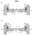
- FIG. 1 is a view showing a rear wheel toe angle control system of a vehicle according to a prior art.
- a rear wheel toe angle control system 20 includes a pair of actuators 22 and 23 respectively installed to the left and right ends of a rear cross member 12, and links 26 and 27 for connecting the actuators 22 and 23 to left and right rear wheels 14 and 15 and changing toe angles of the left and right rear wheels 14 and 15 by means of rods 24 and 25 installed to the actuators 22 and 23 to be translated.
- the actuators 22 and 23 are hydraulic actuators. As the rods 24 and 25 of the actuators 22 and 23 are translated, the links 26 and 27 control the toe angles of the left and right rear wheels 14 and 15.
- the conventional rear wheel toe angle control system 20 of a vehicle so configured operates the actuators 22 and 23 when the vehicle turns to prevent the vehicle from oversteering or understeering.
- the applicant has recently developed a rear wheel toe angle control system of a vehicle, to which an electric-powered actuator is applied in order to rapidly control toe angles of the rear wheels 14 and 15 by improving a slow response of a hydraulic actuator.
- an upper portion of a housing is mounted with a limit sensor of a hall sensor type, which includes a hall element and a permanent magnet to stably control the position of the rod.
- a guide made of non-magnetic material is installed around the permanent magnet so as to improve a sensing ability of the hall element by concentrating magnetic flux of the permanent magnet.
- the electric-powered actuator is configured so that the guide is slidably coupled to the inner surface of the housing to guide a linear movement of the rod.
- the aforementioned rear wheel toe angle control system of a vehicle in which the actuators are mounted to left and right portions of a rear wheel cross member, controls a toe angle of an outer wheel of a turning vehicle in order to control an oversteering phenomenon of the vehicle in turning, thereby increasing a friction force between the tire and a road surface and thus controlling the yaw rate of the vehicle.
- the conventional rear wheel toe angle control system 20 of a vehicle is provided with the two actuators 22 and 23 for controlling the left and right rear wheels 14 and 15. Accordingly, there is a limit in installing the actuators 22 and 23 due to a narrow installation space, and the two actuators 22 and 23 increase weight and manufacturing costs of a vehicle. In addition, since the two actuators 22 and 23 are used in the prior art, the toe angles of the left and right rear wheels 14 and 15 may be controlled differently, which results in unstable control of a stability of the vehicle.
- An object of the present invention is to provide a rear wheel toe angle control system, in which as an actuator for controlling rear wheels of a vehicle, an electric-powered one is used for rapid operation thereof, thereby ensuring handling stability, the left and right rear wheels are operated by the single actuator to reduce weight and manufacturing costs of a vehicle, and toe angles of the left and right rear wheels are identically: controlled to improve handling stability of a vehicle.
- a rear wheel toe angle control system of a vehicle comprising left and right rear wheels supported by a cross member of a vehicle; left and right link members;, each link member having an ead connected to the left and right rear wheels; a rack bar having both ends respectively connected to the left and right link members; a case installed to the cross member to receiving the rack bar; and an actuator installed to the rack bar to cooperate therewith, the actuator moving the rack bar so that the left and right link members change toe angles of the left and right rear wheels at the same time.
- the actuator includes a driving motor installed in a housing; a ring gear to be rotated by the driving motor; a first pinion gear meshed with the ring gear; and a second pinion gear installed to a rotary shaft of the first pinion gear and meshed with the rack bar.
- the rear wheel toe angle control system of a vehicle may further comprise a limit switch installed in the case to detect a moving line of the rack bar, the limit switch controlling the operation of the actuator when a detected end of the rack bar is located to an initial position or an excessively moved position.
- the rear wheel toe angle control system of a vehicle may further comprising a magnetic ring installed to the rotary shaft of the first and second pinion gears; and a magnetic sensor installed to the housing surrounding the ring gear to detect a magnetic force of the magnetic ring, wherein a linear displacement of the rack bar is measured by converting a rotation amount of the magnetic ring with a reduction ratio according to a gear ratio of the first gear and the ring gear and a pitch ratio of racks of the rack bar to the second pinion gear.
- FIG. 2 is a view showing a rear wheel toe angle control system of a vehicle according to the present invention
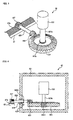
- FIG. 3 is a perspective view schematically showing the rear wheel toe angle control system of a vehicle according to the present invention
- FIG. 4 is a sectional view showing a major portion of the rear wheel toe angle control system of a vehicle according to the present invention.
- left and right rear wheels 54 and 55 of a vehicle are suspended by a rear cross member S2.
- the rear wheels 54 and 55 are coupled to knuckles 56, which are supported by control arms 57 in a lateral direction of the vehicle and supported by trailing arms (not shown) in a longitudinal direction of the vehicle.
- each of the knuckles 56 is supported by a spring 58 and a shock absorber 59 in a vertical direction.
- a rear wheel toe angle control system 60 is installed to the left and right rear wheels 54 and 55 to change toe angles of the rear wheels 54 and 55 when the vehicle turns.
- the rear wheel toe angle control system 60 includes a case 66 installed in parallel with the cross member 52 and a rack bar 67 received in the case 66.
- the rack bar 67 is movably supported in the case 66, and a plurality of rack teeth 67a are formed on a surface of the rack bar 67.
- link members 64 and 65 connected to the left and right rear wheels 54 and 55 are connected to both ends of the rack bar 67, respectively.
- the link members 64 and 65 are movably installed, and each of them may be composed of one or more members and its rotation center may be fixed to a side of the cross member 52.
- the link members 64 and 65 control the toe angles of the left and right rear wheels 54 and 55 by the translation of the rack bar 67.
- an actuator 62 is installed in order to translate the rack bar 67.
- the rack bar 67 is moved to move the link members 64 and 65, whereby the toe angles of the left and right rear wheels 54 and 55 are changed at the same time. That is, when the vehicle turns, one of the left and right rear wheels 54 and 55 is toed in and the other is toed out according to the turning direction, thereby controlling the stability of the turning vehicle.
- the actuator 62 includes a housing 621, and a driving motor 622 installed in the housing 621.
- a gear unit 623b with a predetermined length is formed on a rotary shaft 623a of the driving motor 622, and a ring gear 624 is coupled to the gear unit 623b.
- a first pinion gear 625 is meshed with gear teeth of the ring gear 624.
- the ring gear 624 and the first pinion gear 625 have helical gear teeth having a predetermined shape, which conforms to standards.
- a second pinion gear 627 is coupled to an end of a rotary shaft 626 of the first pinion gear 625.
- the second pinion gear 627 is meshed with rack teeth 67a of the rack bar 67.
- the rotary shaft 626 of the first and second pinion gears 625 and 627 are rotatably supported by a bearing 628 installed to the housing 621.
- the driving motor 622 is an electric-powered motor, preferably a DC motor.
- the driving motor 622 is operated at an input voltage of DC 10 to 16V and a rated input voltage of 13.5V.
- a limit switch for limiting a stroke range of the rack bar 67.
- the limit switch is installed in the case 66 to detect a moving line of the rack bar 67.
- the limit switch detects an end of the rack bar 67, and then, the limit switch sets a reference position of the rack bar 67 when the rack bar 67 is placed at its initial position. Also, if the end of the rack bar 67 is moved excessively, the limit switch controls the operation of the actuator 62 to stop.
- the single actuator 62 causes the left and right rear wheels 54 and 55 to be changed together, thereby improving the reliability of the stability control.
- the reliability of stability control and thus the handling stability are further improved.
- a magnetic ring 626a installed to the rotary shaft 623a of the first and second pinion gears 625 and 627, and a magnetic sensor 629 installed to the housing 621 surrounding the ring gear 624 to detect a magnetic force of the magnetic ring 626a.
- a linear displacement of the rack bar 67 may be measured from a rotation amount of the magnetic ring 626a, a gear ratio between the first pinion gear 625 and the ring gear 624, and a pitch ratio of rack teeth 67a of the rack bar 67 to the second pinion gear 627.
- magnetic rings 626a are installed to the rotary shaft 626 of the first and second pinion gears 625 and 627 in order to measure a rotation amount of the driving motor 622.
- a magnetic sensor 629 for detecting a magnetic force of the magnetic ring 626a is installed to the housing 621 surrounding the ring gear 624 to be at a position adjacent to the magnetic ring 626a.
- a magnetic signal detected from the magnetic sensor 629 is sent to a central processing unit of the vehicle, and the central processing unit may calculate a rotation amount of the rotary shaft 623a caused by the driving motor 622.
- the linear displacement of the rack bar 67 may be measured by measuring a rotation amount of the magnetic ring 626a and then converting the rotation amount with a reduction ratio according to a gear ratio between the first pinion gear 625 and the ring gear 624 and a pitch ratio of the rack teeth 67a of the rack bar 67 to the second pinion gear 627,
- the toe angles of the left and right rear wheels 54 and 55 are controlled according to the measured linear displacement of the rack bar 67.
- the actuator 62 of the rear wheel toe angle control system 60 is operated to prevent the vehicle from understeering or oversteering. More specifically, if power is supplied to the driving motor 622 of the actuator 62, the driving motor 622 rotates and transmits the rotating force to the ring gear 624. In addition, the rotation of the ring gear 624 rotates the first pinion gear 625 meshed with the ring gear 624, so that the second pinion gear 627 connected to the first pinion gear 625 via the rotary shaft 626 is rotated.
- the second pinion gear 627 is meshed with the racks of the rack bar 67 thus to be rotated, thereby moving the tack bar 67.
- an output of the actuator 62 can be controled according to a reduction ratio of the ring gear 624 and the first and second pinion gears 625 and 627.
- the rack bar 67 is moved in any one of the right and left directions by means of the actuator 62, thus moving the link members 64 and 65 connected to the left and right rear wheels 54 and 55.
- the link members 64 and 65 controls the toe angles of the left and right rear wheels 54 and 55 at the same time, and cause one of them to be toed in and the other to be toed out, thereby preventing the vehicle from understeering or oversteering.
- the rear wheel toe angle control system 60 controls an instability of the vehicle caused by the toe-out of the suspension generated when the vehicle turns by controlling the outer wheel to be toed in and the inner wheel to be toed out by means of the actuator 62, thereby ensuring the stability control and therefore the handling stability of the vehicle through the frictional force between the tire and the road surface.
- the toe angles of the rear wheels 54 and 55 may be controlled according to the linear displacement of the rack bar 67.
- the magnetic sensor 629 measures a magnetic force of the magnetic ring installed to the rotary shaft 626 of the first and second pinion gears 625 and 627, thus to determine a rotation amount of the driving motor 622 by means of the rotation amount of the magnetic ring 626a.
- the linear displacement of the rack bar 67 may be measured by converting the rotation amount of the driving motor with a reduction ratio according to a gear ratio between the first pinion gear 625 and the ring gear 624 and a pitch ratio of the racks of the rack bar to the second pinion gear 627.
- an initial start position of the rack bar 67 is set by the limit switch, so that a stroke range of the rack bar 67 is accurately controlled.
- the limit switch detects the end of the rack bar 67 and controls the operation of the actuator 62 so that the rack bar 67 is not excessively moved.
- the toe angles of the rear wheels are operated by the electric-powered actuator having good response and rapid operation, whereby the handling stability can be improved.
- the handling stability is further improved by the control of the toe angles of the left and right rear wheels.
- the rear wheel toe angle control system has a small size, thereby ensuring easy installation and reducing the weight and manufacturing costs of the vehicle.
- the actuator is configured to transfer a driving force by means of a combination of a ring gear and a pinion gear, the driving force can be accurately transferred without loss.
- the control system of the present invention can control an output of actuator by adjusting a reduction ratio between the ring gear and the pinion gear.
Landscapes
- Engineering & Computer Science (AREA)
- Mechanical Engineering (AREA)
- Chemical & Material Sciences (AREA)
- Combustion & Propulsion (AREA)
- Transportation (AREA)
- Vehicle Body Suspensions (AREA)
- Power Steering Mechanism (AREA)
- Steering-Linkage Mechanisms And Four-Wheel Steering (AREA)
Abstract
Description
- The present invention relates to a vehicle dynamic control system for improving handling stability by controlling a dynamics of the vehicle, and more particularly, to a rear wheel toe angle control system of a vehicle, in which both rear wheels with toe angles changeable according to a driving state of the vehicle are operated by a single reduction gear, whereby the toe angles of both the rear wheels are synchronized to be always constantly changed and also the vehicle may reduce its size and weight.
- In general, a suspension installed to a vehicle is provided between a vehicle body and a wheel and connects both the rigid bodies to each other using one or more links. The suspension includes a trailing arm, a knuckle, a control arm and the like.
- The suspension effectively absorbs irregular inputs of a road surface occurring in vehicle driving, thereby providing ride comfort. Also, the suspension appropriately controls the roll of the vehicle body caused from driver's steering or unevenness of a road surface, thereby giving convenience to the driver. In addition, the suspension keeps vertical loads on a contact surface of a tire at a suitable level when the vehicle runs on an irregular road, thereby ensuring handling stability of the vehicle when the vehicle turns or is braked.
- Meanwhile, when a vehicle turns, it may oversteer or understeer due to vehicle velocity or friction with the road surface, thereby deteriorating the handling stability of the vehicle. In order to solve this problem, the
Korean Patent No. 511742 (August 25, 2005 - FIG. 1 is a view showing a rear wheel toe angle control system of a vehicle according to a prior art. Referring to FIG. 1, a rear wheel toe
angle control system 20 includes a pair ofactuators rear cross member 12, andlinks actuators rear wheels rear wheels rods actuators - The
actuators rods actuators links rear wheels - The conventional rear wheel toe
angle control system 20 of a vehicle so configured operates theactuators - Meanwhile, the applicant has recently developed a rear wheel toe angle control system of a vehicle, to which an electric-powered actuator is applied in order to rapidly control toe angles of the
rear wheels - In the electric-powered actuator, an upper portion of a housing is mounted with a limit sensor of a hall sensor type, which includes a hall element and a permanent magnet to stably control the position of the rod. A guide made of non-magnetic material is installed around the permanent magnet so as to improve a sensing ability of the hall element by concentrating magnetic flux of the permanent magnet. The electric-powered actuator is configured so that the guide is slidably coupled to the inner surface of the housing to guide a linear movement of the rod.
- The aforementioned rear wheel toe angle control system of a vehicle, in which the actuators are mounted to left and right portions of a rear wheel cross member, controls a toe angle of an outer wheel of a turning vehicle in order to control an oversteering phenomenon of the vehicle in turning, thereby increasing a friction force between the tire and a road surface and thus controlling the yaw rate of the vehicle.
- However, the conventional rear wheel toe
angle control system 20 of a vehicle is provided with the twoactuators rear wheels actuators actuators actuators rear wheels - The present invention is conceived to solve the aforementioned problems in the prior art. An object of the present invention is to provide a rear wheel toe angle control system, in which as an actuator for controlling rear wheels of a vehicle, an electric-powered one is used for rapid operation thereof, thereby ensuring handling stability, the left and right rear wheels are operated by the single actuator to reduce weight and manufacturing costs of a vehicle, and toe angles of the left and right rear wheels are identically: controlled to improve handling stability of a vehicle.
- According to an aspect of the present invention for achieving the objects, there is provided a rear wheel toe angle control system of a vehicle, comprising left and right rear wheels supported by a cross member of a vehicle; left and right link members;, each link member having an ead connected to the left and right rear wheels; a rack bar having both ends respectively connected to the left and right link members; a case installed to the cross member to receiving the rack bar; and an actuator installed to the rack bar to cooperate therewith, the actuator moving the rack bar so that the left and right link members change toe angles of the left and right rear wheels at the same time. The actuator includes a driving motor installed in a housing; a ring gear to be rotated by the driving motor; a first pinion gear meshed with the ring gear; and a second pinion gear installed to a rotary shaft of the first pinion gear and meshed with the rack bar.
- The rear wheel toe angle control system of a vehicle may further comprise a limit switch installed in the case to detect a moving line of the rack bar, the limit switch controlling the operation of the actuator when a detected end of the rack bar is located to an initial position or an excessively moved position. In addition, the rear wheel toe angle control system of a vehicle may further comprising a magnetic ring installed to the rotary shaft of the first and second pinion gears; and a magnetic sensor installed to the housing surrounding the ring gear to detect a magnetic force of the magnetic ring, wherein a linear displacement of the rack bar is measured by converting a rotation amount of the magnetic ring with a reduction ratio according to a gear ratio of the first gear and the ring gear and a pitch ratio of racks of the rack bar to the second pinion gear.
- The above and other objects, features and advantages of the present invention will become apparent from the following description of a preferred embodiment given in conjunction with the accompanying drawings, in which:
- FIG. 1 is a view showing a rear wheel toe angle control system of a vehicle according to a prior art;
- FIG. 2 is a view showing a rear wheel toe angle control system of a vehicle according to the present invention;
- FIG. 3 is a perspective view schematically showing the rear wheel toe angle control system of a vehicle according to the present invention; and
- FIG. 4 is a sectional view showing a major portion of the rear wheel toe angle control system of a vehicle according to the present invention.
- Hereinafter, a preferred embodiment of the present invention will be described in detail with reference to the accompanying drawings.
- FIG. 2 is a view showing a rear wheel toe angle control system of a vehicle according to the present invention, FIG. 3 is a perspective view schematically showing the rear wheel toe angle control system of a vehicle according to the present invention, and FIG. 4 is a sectional view showing a major portion of the rear wheel toe angle control system of a vehicle according to the present invention.
- Referring to FIGS. 2 to 4, left and right
rear wheels rear wheels knuckles 56, which are supported bycontrol arms 57 in a lateral direction of the vehicle and supported by trailing arms (not shown) in a longitudinal direction of the vehicle. In addition, each of theknuckles 56 is supported by aspring 58 and a shock absorber 59 in a vertical direction. - Meanwhile, a rear wheel toe
angle control system 60 is installed to the left and rightrear wheels rear wheels - The rear wheel toe
angle control system 60 includes acase 66 installed in parallel with thecross member 52 and arack bar 67 received in thecase 66. Therack bar 67 is movably supported in thecase 66, and a plurality of rack teeth 67a are formed on a surface of therack bar 67. - In addition, a pair of
link members rear wheels rack bar 67, respectively. Thelink members cross member 52. - Meanwhile, the
link members rear wheels rack bar 67. To this end, anactuator 62 is installed in order to translate therack bar 67. - Accordingly, as the
actuator 62 operates, therack bar 67 is moved to move thelink members rear wheels rear wheels - The
actuator 62 includes ahousing 621, and adriving motor 622 installed in thehousing 621. In addition, a gear unit 623b with a predetermined length is formed on arotary shaft 623a of thedriving motor 622, and aring gear 624 is coupled to the gear unit 623b. Further, afirst pinion gear 625 is meshed with gear teeth of thering gear 624. At this time, thering gear 624 and thefirst pinion gear 625 have helical gear teeth having a predetermined shape, which conforms to standards. Furthermore, asecond pinion gear 627 is coupled to an end of arotary shaft 626 of thefirst pinion gear 625. Thesecond pinion gear 627 is meshed with rack teeth 67a of therack bar 67. Here, therotary shaft 626 of the first andsecond pinion gears bearing 628 installed to thehousing 621. - In addition, the
driving motor 622 is an electric-powered motor, preferably a DC motor. In this embodiment, thedriving motor 622 is operated at an input voltage of DC 10 to 16V and a rated input voltage of 13.5V. - Meanwhile, in the
case 66, there is provided a limit switch for limiting a stroke range of therack bar 67. The limit switch is installed in thecase 66 to detect a moving line of therack bar 67. - In addition, the limit switch detects an end of the
rack bar 67, and then, the limit switch sets a reference position of therack bar 67 when therack bar 67 is placed at its initial position. Also, if the end of therack bar 67 is moved excessively, the limit switch controls the operation of theactuator 62 to stop. - According to the rear wheel toe
angle control system 60 of a vehicle configured as described above, thesingle actuator 62 causes the left and rightrear wheels - In addition, there are provided a
magnetic ring 626a installed to therotary shaft 623a of the first and second pinion gears 625 and 627, and amagnetic sensor 629 installed to thehousing 621 surrounding thering gear 624 to detect a magnetic force of themagnetic ring 626a. Thus, a linear displacement of therack bar 67 may be measured from a rotation amount of themagnetic ring 626a, a gear ratio between thefirst pinion gear 625 and thering gear 624, and a pitch ratio of rack teeth 67a of therack bar 67 to thesecond pinion gear 627. - In addition,
magnetic rings 626a are installed to therotary shaft 626 of the first and second pinion gears 625 and 627 in order to measure a rotation amount of the drivingmotor 622. Also, amagnetic sensor 629 for detecting a magnetic force of themagnetic ring 626a is installed to thehousing 621 surrounding thering gear 624 to be at a position adjacent to themagnetic ring 626a. In addition, a magnetic signal detected from themagnetic sensor 629 is sent to a central processing unit of the vehicle, and the central processing unit may calculate a rotation amount of therotary shaft 623a caused by the drivingmotor 622. - Meanwhile, the linear displacement of the
rack bar 67 may be measured by measuring a rotation amount of themagnetic ring 626a and then converting the rotation amount with a reduction ratio according to a gear ratio between thefirst pinion gear 625 and thering gear 624 and a pitch ratio of the rack teeth 67a of therack bar 67 to thesecond pinion gear 627, In addition, the toe angles of the left and rightrear wheels rack bar 67. - The operation of the rear wheel toe angle control system of a vehicle so configured will be described as follows.
- When a vehicle runs, particularly turns, it may understeer or oversteer due to gravity of a vehicle body or friction with a road surface. At this time, the
actuator 62 of the rear wheel toeangle control system 60 is operated to prevent the vehicle from understeering or oversteering. More specifically, if power is supplied to the drivingmotor 622 of theactuator 62, the drivingmotor 622 rotates and transmits the rotating force to thering gear 624. In addition, the rotation of thering gear 624 rotates thefirst pinion gear 625 meshed with thering gear 624, so that thesecond pinion gear 627 connected to thefirst pinion gear 625 via therotary shaft 626 is rotated. Thesecond pinion gear 627 is meshed with the racks of therack bar 67 thus to be rotated, thereby moving thetack bar 67. At this time, an output of theactuator 62 can be controled according to a reduction ratio of thering gear 624 and the first and second pinion gears 625 and 627. As mentioned above, therack bar 67 is moved in any one of the right and left directions by means of theactuator 62, thus moving thelink members rear wheels link members rear wheels - That is, the rear wheel toe
angle control system 60 controls an instability of the vehicle caused by the toe-out of the suspension generated when the vehicle turns by controlling the outer wheel to be toed in and the inner wheel to be toed out by means of theactuator 62, thereby ensuring the stability control and therefore the handling stability of the vehicle through the frictional force between the tire and the road surface. - At this time, the toe angles of the
rear wheels rack bar 67. To this end, themagnetic sensor 629 measures a magnetic force of the magnetic ring installed to therotary shaft 626 of the first and second pinion gears 625 and 627, thus to determine a rotation amount of the drivingmotor 622 by means of the rotation amount of themagnetic ring 626a. Then, the linear displacement of therack bar 67 may be measured by converting the rotation amount of the driving motor with a reduction ratio according to a gear ratio between thefirst pinion gear 625 and thering gear 624 and a pitch ratio of the racks of the rack bar to thesecond pinion gear 627. - Meanwhile, an initial start position of the
rack bar 67 is set by the limit switch, so that a stroke range of therack bar 67 is accurately controlled. In addition, the limit switch detects the end of therack bar 67 and controls the operation of theactuator 62 so that therack bar 67 is not excessively moved. - According to the rear wheel toe angle control system of a vehicle of the present invention so configured, the toe angles of the rear wheels are operated by the electric-powered actuator having good response and rapid operation, whereby the handling stability can be improved. In addition, since the left and right rear wheels are operated by the single actuator, the handling stability is further improved by the control of the toe angles of the left and right rear wheels. Moreover, the rear wheel toe angle control system has a small size, thereby ensuring easy installation and reducing the weight and manufacturing costs of the vehicle, In addition, since the actuator is configured to transfer a driving force by means of a combination of a ring gear and a pinion gear, the driving force can be accurately transferred without loss. Moreover, the control system of the present invention can control an output of actuator by adjusting a reduction ratio between the ring gear and the pinion gear.
- As mentioned above, the rear wheel toe angle control system of a vehicle according to the present invention has been illustrated with reference to the accompanying drawings, but the present invention is not limited to the aforementioned embodiments and drawings. It will be apparent that those skilled in the art can make various modifications and changes thereto within the scope of the invention defined by the claims.
Claims (3)
- A rear wheel toe angle control system of a vehicle, comprising:left and right rear wheels supported by a cross member of a vehicle;left and right link members, each link member having an end connected to the left and right rear wheels;a rack bar having both ends respectively connected to the left and right link members;a case installed to the cross member to receiving the rack bar; andan actuator installed to the rack bar to cooperate therewith, the actuator moving the rack bar so that the left and right link members change toe angles of the left and right rear wheels at the same time,wherein the actuator includes a driving motor installed in a housing; a ring gear to be rotated by the driving motor; a first pinion gear meshed with the ring gear; and a second pinion gear installed to a rotary shaft of the first pinion gear and meshed with the rack bar.
- The rear wheel toe angle control system as claimed in claim 1, further comprising a limit switch installed in the case to detect a moving line of the rack bar, the limit switch controlling the operation of the actuator when a detected end of the rack bar is located to an initial position or an excessively moved position.
- The rear wheel toe angle control system as claimed in claim 1 or 2, further comprising a magnetic ring installed to the rotary shaft of the first and second pinion gears; and a magnetic sensor installed to the housing surrounding the ring gear to detect a magnetic force of the magnetic ring, wherein a linear displacement of the rack bar is measured by converting a rotation amount of the magnetic ring with a reduction ratio according to a gear ratio of the first gear and the ring gear and a pitch ratio of racks of the rack bar to the second pinion gear.
Applications Claiming Priority (1)
| Application Number | Priority Date | Filing Date | Title |
|---|---|---|---|
| KR1020060087860A KR100748350B1 (en) | 2006-09-12 | 2006-09-12 | Rear wheel toe control of car |
Publications (1)
| Publication Number | Publication Date |
|---|---|
| EP1900603A1 true EP1900603A1 (en) | 2008-03-19 |
Family
ID=38602577
Family Applications (1)
| Application Number | Title | Priority Date | Filing Date |
|---|---|---|---|
| EP07000337A Withdrawn EP1900603A1 (en) | 2006-09-12 | 2007-01-09 | Real wheel toe angle control system of vehicle |
Country Status (5)
| Country | Link |
|---|---|
| US (1) | US7325818B1 (en) |
| EP (1) | EP1900603A1 (en) |
| JP (1) | JP2008068853A (en) |
| KR (1) | KR100748350B1 (en) |
| CN (1) | CN101143600A (en) |
Families Citing this family (15)
| Publication number | Priority date | Publication date | Assignee | Title |
|---|---|---|---|---|
| JP2008055921A (en) * | 2006-08-29 | 2008-03-13 | Honda Motor Co Ltd | Vehicle rear wheel toe angle variable control device |
| JP4448838B2 (en) * | 2006-08-25 | 2010-04-14 | 本田技研工業株式会社 | Vehicle toe angle variable control device |
| KR101316421B1 (en) | 2007-08-31 | 2013-10-08 | 현대자동차주식회사 | Active controlling method of steering for vehicle |
| ATE520581T1 (en) * | 2008-03-10 | 2011-09-15 | Honda Motor Co Ltd | VEHICLE WITH REAR WHEEL STEERING |
| US8126612B2 (en) * | 2008-10-27 | 2012-02-28 | Concordia University | Steering system and method for independent steering of wheels |
| CN101628528B (en) * | 2009-05-15 | 2011-03-23 | 邵延 | Wheel link structure |
| US8205892B2 (en) * | 2010-07-30 | 2012-06-26 | Deere & Company | Method of automatically changing wheel toe angle |
| US8480099B2 (en) * | 2011-06-13 | 2013-07-09 | Scott S. Porta | Apparatus and method for adjusting toe angle in the wheels of a solid axle |
| JP5738234B2 (en) | 2012-05-30 | 2015-06-17 | 本田技研工業株式会社 | Rear wheel toe angle variable vehicle |
| CN104512456A (en) * | 2013-09-27 | 2015-04-15 | 北汽福田汽车股份有限公司 | Automobile, power steering gear, and control method of power steering gear |
| CN106114614B (en) * | 2016-08-26 | 2018-05-18 | 吉林大学 | A kind of controlled hydraulic locking type left and right wheels independent steering gear |
| KR102104748B1 (en) * | 2019-05-14 | 2020-04-24 | 문윤경 | Apparatus for steering a vehicle |
| JP2023545157A (en) * | 2020-10-13 | 2023-10-26 | ドォフテック ピーティーワイ リミテッド | wheel alignment system |
| KR20230052465A (en) * | 2021-10-13 | 2023-04-20 | 현대자동차주식회사 | Independent Corner Module |
| DE102022116729A1 (en) * | 2022-07-05 | 2024-01-11 | Schaeffler Technologies AG & Co. KG | Actuator and chassis for vehicle |
Citations (5)
| Publication number | Priority date | Publication date | Assignee | Title |
|---|---|---|---|---|
| EP0376456A2 (en) * | 1988-12-28 | 1990-07-04 | Ford Motor Company Limited | Steering system position detector |
| EP0460664A1 (en) * | 1990-06-06 | 1991-12-11 | Koyo Seiko Co., Ltd. | Four-wheel steering apparatus |
| US5487439A (en) * | 1992-04-28 | 1996-01-30 | Kayaba Industry Co., Ltd. | Rear wheel steering device |
| DE19720602A1 (en) * | 1996-05-27 | 1998-01-15 | Honda Motor Co Ltd | Four wheel steering control system for vehicle |
| US20030028305A1 (en) * | 2001-08-01 | 2003-02-06 | Boswell Karen A. | Static steering angle reducing algorithm for four wheel steering systems |
Family Cites Families (15)
| Publication number | Priority date | Publication date | Assignee | Title |
|---|---|---|---|---|
| US3756188A (en) * | 1972-03-01 | 1973-09-04 | Wolverine Pentronix | Boat steering and reversing system |
| JPS6218309A (en) | 1985-07-17 | 1987-01-27 | Daihatsu Motor Co Ltd | Toe-angle controller for rear wheel of car |
| US5026081A (en) | 1990-01-25 | 1991-06-25 | General Motors Corporation | Rear wheel steering system having toe error compensation |
| DE4020547A1 (en) * | 1990-06-28 | 1992-01-02 | Porsche Ag | DEVICE FOR ACTIVE ADJUSTMENT OF A MOTOR VEHICLE WHEEL |
| US5549319A (en) | 1994-08-24 | 1996-08-27 | L & W Engineering Company | Toe-in angle adjustment for vehicle wheels |
| JPH10218008A (en) | 1997-02-12 | 1998-08-18 | Honda Motor Co Ltd | Toe angle control device in vehicle |
| GB2339750B (en) | 1998-07-24 | 2001-02-07 | Toyoda Automatic Loom Works | Steering device for vehicle |
| DE19857394C2 (en) * | 1998-12-12 | 2000-11-23 | Daimler Chrysler Ag | Adjustable suspension system for an active chassis of a motor vehicle |
| JP2001097240A (en) | 1999-09-30 | 2001-04-10 | Toyota Autom Loom Works Ltd | Toe angle adjusting mechanism and steering device for wheel in vehicle |
| US6719311B2 (en) | 2001-03-01 | 2004-04-13 | Dana Corporation | Vehicle steering assembly |
| JP2003087219A (en) * | 2001-09-07 | 2003-03-20 | Mitsubishi Cable Ind Ltd | Device and method for removing interference |
| JP2003087221A (en) * | 2001-09-13 | 2003-03-20 | Matsushita Electric Ind Co Ltd | CDMA reception demodulation apparatus and CDMA reception demodulation method |
| US6962356B2 (en) * | 2002-05-08 | 2005-11-08 | Mando Corporation | Active toe angle adjustment mechanism |
| EP1361087B1 (en) * | 2002-05-08 | 2014-08-06 | Mando Corporation | Active toe angle adjustment mechanism |
| JP2005297782A (en) * | 2004-04-12 | 2005-10-27 | Toyota Motor Corp | Toe angle adjustment mechanism |
-
2006
- 2006-09-12 KR KR1020060087860A patent/KR100748350B1/en not_active Expired - Fee Related
-
2007
- 2007-01-09 EP EP07000337A patent/EP1900603A1/en not_active Withdrawn
- 2007-01-30 JP JP2007018750A patent/JP2008068853A/en active Pending
- 2007-02-01 CN CNA2007100079916A patent/CN101143600A/en active Pending
- 2007-02-23 US US11/678,083 patent/US7325818B1/en not_active Expired - Fee Related
Patent Citations (5)
| Publication number | Priority date | Publication date | Assignee | Title |
|---|---|---|---|---|
| EP0376456A2 (en) * | 1988-12-28 | 1990-07-04 | Ford Motor Company Limited | Steering system position detector |
| EP0460664A1 (en) * | 1990-06-06 | 1991-12-11 | Koyo Seiko Co., Ltd. | Four-wheel steering apparatus |
| US5487439A (en) * | 1992-04-28 | 1996-01-30 | Kayaba Industry Co., Ltd. | Rear wheel steering device |
| DE19720602A1 (en) * | 1996-05-27 | 1998-01-15 | Honda Motor Co Ltd | Four wheel steering control system for vehicle |
| US20030028305A1 (en) * | 2001-08-01 | 2003-02-06 | Boswell Karen A. | Static steering angle reducing algorithm for four wheel steering systems |
Also Published As
| Publication number | Publication date |
|---|---|
| US7325818B1 (en) | 2008-02-05 |
| JP2008068853A (en) | 2008-03-27 |
| KR100748350B1 (en) | 2007-08-09 |
| CN101143600A (en) | 2008-03-19 |
Similar Documents
| Publication | Publication Date | Title |
|---|---|---|
| US7325818B1 (en) | Rear wheel toe angle control system of vehicle | |
| JP6476235B2 (en) | Steering and control system for tricycles | |
| CN103448799B (en) | Rear wheel toe angle variable vehicle | |
| EP2078663B1 (en) | Vehicle with a variable rear toe angle | |
| CN101405155B (en) | Vehicle stabilizer system | |
| CN102452412B (en) | Vehicle steering apparatus | |
| JP5433023B2 (en) | Rear wheel toe angle control device for vehicle | |
| JP4633175B2 (en) | Rear wheel toe angle controller | |
| EP1859970B1 (en) | Rear wheel toe angle control system of vehicle | |
| WO2009104497A1 (en) | Rear wheel steering apparatus for a vehicle | |
| JP4505508B2 (en) | Rear wheel toe angle variable vehicle | |
| JP2016135642A (en) | Rear wheel steering device | |
| JP2009161099A (en) | Rear wheel toe angle variable vehicle | |
| JP4987779B2 (en) | Rear wheel toe angle control device for vehicle | |
| JP2011131859A (en) | Electric actuator control device, and vehicle rear wheel toe angle control device having the same | |
| JP5478027B2 (en) | Rear wheel steering device | |
| JP2009234547A (en) | Rear wheel steering control device | |
| JP2009006876A (en) | Steering device, automobile and rack housing mounting method | |
| JP6535071B2 (en) | Steering actuator and vehicle | |
| JP4935137B2 (en) | Suspension device | |
| KR101446945B1 (en) | Actuator for active geometry control suspension system | |
| JP2009214774A (en) | Rear wheel steering control device |
Legal Events
| Date | Code | Title | Description |
|---|---|---|---|
| PUAI | Public reference made under article 153(3) epc to a published international application that has entered the european phase |
Free format text: ORIGINAL CODE: 0009012 |
|
| AK | Designated contracting states |
Kind code of ref document: A1 Designated state(s): AT BE BG CH CY CZ DE DK EE ES FI FR GB GR HU IE IS IT LI LT LU LV MC NL PL PT RO SE SI SK TR |
|
| AX | Request for extension of the european patent |
Extension state: AL BA HR MK YU |
|
| 17P | Request for examination filed |
Effective date: 20080514 |
|
| R17P | Request for examination filed (corrected) |
Effective date: 20080516 |
|
| 17Q | First examination report despatched |
Effective date: 20080912 |
|
| AKX | Designation fees paid |
Designated state(s): DE FR GB IT |
|
| STAA | Information on the status of an ep patent application or granted ep patent |
Free format text: STATUS: THE APPLICATION HAS BEEN WITHDRAWN |
|
| 18W | Application withdrawn |
Effective date: 20090128 |