EP1900575A2 - Safety bar, particulary for industrial vehicles - Google Patents
Safety bar, particulary for industrial vehicles Download PDFInfo
- Publication number
- EP1900575A2 EP1900575A2 EP07425548A EP07425548A EP1900575A2 EP 1900575 A2 EP1900575 A2 EP 1900575A2 EP 07425548 A EP07425548 A EP 07425548A EP 07425548 A EP07425548 A EP 07425548A EP 1900575 A2 EP1900575 A2 EP 1900575A2
- Authority
- EP
- European Patent Office
- Prior art keywords
- bar
- section bar
- safety
- section
- safety bar
- Prior art date
- Legal status (The legal status is an assumption and is not a legal conclusion. Google has not performed a legal analysis and makes no representation as to the accuracy of the status listed.)
- Granted
Links
- 230000004224 protection Effects 0.000 claims abstract description 28
- 239000000463 material Substances 0.000 claims abstract description 12
- 239000004033 plastic Substances 0.000 claims abstract description 11
- 229920003023 plastic Polymers 0.000 claims abstract description 11
- 229910052751 metal Inorganic materials 0.000 claims abstract description 4
- 239000002184 metal Substances 0.000 claims abstract description 4
- 230000008878 coupling Effects 0.000 claims description 20
- 238000010168 coupling process Methods 0.000 claims description 20
- 238000005859 coupling reaction Methods 0.000 claims description 20
- 229910000831 Steel Inorganic materials 0.000 claims description 17
- 239000010959 steel Substances 0.000 claims description 17
- HCHKCACWOHOZIP-UHFFFAOYSA-N Zinc Chemical compound [Zn] HCHKCACWOHOZIP-UHFFFAOYSA-N 0.000 claims description 5
- 229910001220 stainless steel Inorganic materials 0.000 claims description 5
- 239000010935 stainless steel Substances 0.000 claims description 5
- 229910052725 zinc Inorganic materials 0.000 claims description 5
- 239000011701 zinc Substances 0.000 claims description 5
- 239000004743 Polypropylene Substances 0.000 claims description 3
- 238000001125 extrusion Methods 0.000 claims description 3
- -1 polypropylene Polymers 0.000 claims description 3
- 229920001155 polypropylene Polymers 0.000 claims description 3
- 239000004411 aluminium Substances 0.000 description 10
- 229910052782 aluminium Inorganic materials 0.000 description 10
- XAGFODPZIPBFFR-UHFFFAOYSA-N aluminium Chemical compound [Al] XAGFODPZIPBFFR-UHFFFAOYSA-N 0.000 description 10
- 230000004888 barrier function Effects 0.000 description 10
- 230000008901 benefit Effects 0.000 description 6
- 230000035939 shock Effects 0.000 description 5
- 230000003068 static effect Effects 0.000 description 5
- 230000000703 anti-shock Effects 0.000 description 2
- 238000004040 coloring Methods 0.000 description 2
- 238000004519 manufacturing process Methods 0.000 description 2
- 208000027418 Wounds and injury Diseases 0.000 description 1
- 238000004873 anchoring Methods 0.000 description 1
- 208000014674 injury Diseases 0.000 description 1
- 230000004048 modification Effects 0.000 description 1
- 238000012986 modification Methods 0.000 description 1
- 238000007493 shaping process Methods 0.000 description 1
Images


Classifications
-
- B—PERFORMING OPERATIONS; TRANSPORTING
- B60—VEHICLES IN GENERAL
- B60R—VEHICLES, VEHICLE FITTINGS, OR VEHICLE PARTS, NOT OTHERWISE PROVIDED FOR
- B60R19/00—Wheel guards; Radiator guards, e.g. grilles; Obstruction removers; Fittings damping bouncing force in collisions
- B60R19/56—Fittings damping bouncing force in truck collisions, e.g. bumpers; Arrangements on high-riding vehicles, e.g. lorries, for preventing vehicles or objects from running thereunder
- B60R19/565—Fittings damping bouncing force in truck collisions, e.g. bumpers; Arrangements on high-riding vehicles, e.g. lorries, for preventing vehicles or objects from running thereunder on vehicle sides
Definitions
- the present invention concerns a safety bar, particularly for industrial vehicles.
- the invention relates to a bar for realising structures, such as safety structures or containment devices for instable goods, particularly, but not exclusively, on industrial vehicles, such as trucks, trailers or semi trailers, particularly studied and realised for permitting a high resistance to the mechanical (static and dynamic) stresses and to be less subject to permanent deformations in case of collisions or of loads applied according to a transverse direction.
- structures such as safety structures or containment devices for instable goods, particularly, but not exclusively, on industrial vehicles, such as trucks, trailers or semi trailers, particularly studied and realised for permitting a high resistance to the mechanical (static and dynamic) stresses and to be less subject to permanent deformations in case of collisions or of loads applied according to a transverse direction.
- Safety lateral protections compulsory within the European Community, are included among these setting up, said protections aiming preventing that cycles, motorcycles or other bodies slip, in case of road accident, under the shape of said industrial vehicle, and particularly within the space between wheels.
- industrial vehicles e.g. trailers or semi-trailers for tyre transportation
- a very rigid structural frame comprised of steel beams.
- Load to be transported is placed on the portion above said beams, contained within bodies or frames, comprised of rigid side boards.
- structural frame is the same frame of tractor, and it is usually connected by a suitable snood and positioned above the wheels.
- said load remains in a rather high position.
- Space between the wheels of said vehicle is typically empty, or it is used for storing materials, tool cases, fire extinguishers, wedges and other devices (e.g. compressors for vans provided with isothermal bodies, pallets supports, wheel support, ecc.).
- devices e.g. compressors for vans provided with isothermal bodies, pallets supports, wheel support, ecc.
- lateral protection barriers Most common configuration for a lateral protection presently used by industrial vehicles setting up and manufacturers (MAN, lveco, Renault, Volvo, Scania, DAF, ecc.) provides two aluminium extruded bars, placed horizontally between the wheels according to the longitudinal extension of the vehicle and fixed to the frame by a corresponding number of zinc plated steel or stainless steel sheet uprights. Uprights directly coupled with the vehicle structural frame by removable couplings (screws and nuts) have on their surface a series of slots through which it is possible anchoring the horizontal barriers, being it possible adjusting their distance.
- bodies are employed for loading goods within industrial vehicles, typically comprised of a structure made up of uprights and transverse elements coupled each other.
- said bodies have a bearing structure comprised of four uprights placed at the ends of the frame and a series of transverse elements delimiting their space.
- Structures for containing goods must be completely or partially dismountable so as to open wide openings for loading and unloading goods.
- Said structure of industrial vehicle bodies is presently comprised of a steel section bars or aluminium extrusions frame. More specifically, starting from a base, also known as flatcar, represented by the upper portion of the frame of industrial vehicle or trailers or semi trailers, on which different uprights are mounted, generally at least four, provided at the ends of said flatcar. On the basis of the kind of load and of the stiffness requirements of the vehicle walls, it is possible mounting other uprights so as to reduce the distance between centres of the same.
- Transverse elements or "side boards” are placed between the above mentioned uprights, creating the real lateral wall of the vehicle.
- These steel or anodised aluminium section bars transverse elements are usually inserted within pockets or seats and fixed at their ends on said uprights.
- side boards are comprised of steel
- fixing to the uprights can be realised by fixed joint (movable coupling), or they ate welded on uprights (fixed coupling) on the basis of the specific requirements.
- side boards or barrier are comprised of anodized aluminium extruded elements, they are coupled by fixed joint with uprights and each other.
- Transverse elements and uprights realise a structure and in some cases (movable couplings) it is possible dismounting wide barriers (side boards) to make it easier loading and unloading operations.
- a safety bar particularly for industrial vehicles, characterised in that it comprises a metal section bar, and a plastic material box-type body, said box-type body having a seat, realised along its main extension, within which said section bar can be inserted.
- said section bar can have a substantially “C” shaped, or " ⁇ " shaped section, or a box-type section.
- said box-type body can be realised by extrusion.
- said plastic material can be polypropylene or polivinilchloride (PVC).
- said section bar can be comprised of zinc plated steel or of stainless steel.
- said box-type body can comprise two channels, realised laterally with respect to said seat.
- said bar can comprise means for coupling with supports.
- said bar can have a slot extending along its main direction, or holes, said slot or said holes permitting application of said means for coupling with possible supports to said section bar.
- said means for coupling with supports can comprise a small block, to be inserted within said section bar, having a seat in which the head of a screw and a washer can be placed, said screw projecting from said slot or holes when said small block is inserted in said section bar.
- a lateral protection for an industrial vehicle comprising at least one upright, with a plurality of slots along a surface; a bracket that can be coupled with said at least one upright, in correspondence of one of its ends, and with the frame of said industrial vehicle; and one or more bars coupled with said at least one upright through said slots, said one or more bars being provided laterally with respect to said industrial vehicle toward its longitudinal direction and each other substantially parallel, so as to obstruct the empty space under said industrial vehicle, characterised in that said one or more bar are as defined in the above.
- said one or more bars can be coupled with said at least one upright by coupling means.
- said protection can comprise two uprights.
- said brackets can be fixed to said vehicle by a pair of screws and nuts.
- the position of said at least one upright and the corresponding bracket can be adjusted.
- Said bar 1 comprises a first section bar 2 completely inserted within a box-type body 3.
- Said first section bar 2 is comprised of metal, preferably zinc plated steel or stainless steel.
- section of said first section bar 2 is substantially "C" shaped, but other possible embodiments are for example ⁇ shaped sections, H shaped section or box-type section.
- Box-type body 3 is comprised of plastic material, preferably polivinilchloride (PVC) or polypropylene and comprises two open lateral channels 3' and an open seat 3", between said two channels 3', suitable to house said section bar 2. possibly, said box-type body 3 can be without lateral channels, but only the open seat 3".
- PVC polivinilchloride
- polypropylene polypropylene
- said coupling means are comprised of an assembly comprising (see also figure 2) a small block 5, a hexagonal screw 6 and a washer 7.
- said small block 5 has a parellepiped shape, and has a cavity 8 on one face, within which the head of said screw 6 can be housed, and some projections 9.
- small block 5 is apt to be inserted within the inner channel of the section bar 2. Projections 9, entering within the slot 4, permit preventing rotation each other between bar 1 and small block 5.
- figure 3 shows assembly comprising small block 5, bar 6 and washer 7.
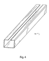
- Figures 4 and 5 show, respectively, first "C” shaped section bar 2 and a further embodiment of box-type body 3, wherein the two closed lateral channels 3' have rounded surfaces 10.
- said bar 1 has a larger efficient surface, due to the surface of the box-type body 3.
- said box-type body 3 When said box-type body 3 receives, for example, a shock, it distributes all energy on said first section bar 2 that, being comprised of steel, on one hand permits better supporting shock, and on the other hand to deform less than the known solutions, maintaining the elastic properties.
- bar 1 according to the invention can be used for different safety setting up of industrial vehicles.
- said bar 1 can be used for realising lateral protections (or cycle barriers) for closing the empty space between axis of the vehicle wheels of industrial vehicles such as trucks, trailers or semi trailers.
- a lateral protection 11 comprised of bars 1 according to the present invention, respectively installed on a truck 12, a trailer 13 or on a semi trailer 14.
- Lateral protection 11 is placed, as shown in figures 6-7, between axes of front wheels and rear wheels, while in figure 8 it is placed in front of the rear wheels, and in any case so as to protect the empty space under the industrial vehicle.
- Said lateral protection 11 comprises, with respect to the prior art, two or more bars 1 according to the invention in lieu of the standard aluminium beams.
- said lateral protections 11 are comprised of two bars 1, placed horizontally between the wheel axes in the longitudinal direction of the industrial vehicle 12, 13 or 14, and anchored to the frame of said vehicle by uprights 15, made up of zinc plated steel or stainless steel sheet.
- Figures 9-11 show an upright 15 having a plurality of slots 16 for fixing the same at the bars 1 by small blocks 5, having screws 6 and nuts 6'.
- Upright 15 that in the present embodiment is a "U" shaped beam, can be fixed to a support bracket 18 by screws 19, 20, 21 and relevant pins 19', 20', 21'.
- Rotation of said upright 15 with respect to said bracket 18 can be adjusted.
- the latter has a plurality of holes 22, in which screw 21 and relevant pin 21' can be introduced.
- Bushings 23 are connected with the upright 15, that can be placed within suitable cavities 24 realised on the lateral surface of said upright 15. said bushings 23 are apt to realise a gasket between said upright 15 and said bracket 18.
- an elastic element 26 can be fixed within said upright 15 by a screw 25, said elastic element 26 having a groove 27 within which pins 19' or 20' can be housed.
- Said support bracket 18 can be fixed to the industrial vehicle frame 12, 13 or 14 by screws 28 and relevant nuts, that can be inserted within the holes 29 realised above the same bracket 18.
- Figure 12 shows a lateral protection 11 comprising slots 16 on which bars 1 are fixed. Said uprights 15 are also fixed to the brackets 18.
- box-type body 3 comprised of plastic material, it can be manufactured so as to have a most pleasant aspect, being it possible shaping its profile or colouring it with the same colour of the industrial vehicle.
- bars 1 it is possible realising body side boards by said bars 1, obtaining remarkable advantages with respect to the use of standard aluminium or steel beams.
- bars 1, even deforming, tend to spring back to the original shape after their intervention, thanks to the mechanical properties of better resistance to static loads and better elasticity.
- box-type element 3 can be so width to permit a better protection and resistance of the body.
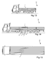
- Figures 13-15 show application of bars 1 on a truck 12 and on a trailer 13 for realising side boards. It is noted in figure 14 that trailer 13 has a protection 11.
- basic feature of the present invention is a new combination of materials so as to obtain bars having better mechanical properties of dynamic and static resistance, and at the same time a better elasticity.
- An advantage of the present invention is that steel section bar has the structural function of resistance to mechanical (dynamic and static) stresses, ensuring a rigid and stiff coupling with the structure. Furthermore, in view of the higher elastic limit with respect to aluminium, steel structural section bar is less subjected to permanent deformations in case of shocks or loads applied transversely.
- outer plastic box-type body has the following advantages:
- a further advantage of the present invention is that of complying with the European Community safety requirement rule n° 89/297/EEC, in which, among the restraint imposed there are included: lack of sharp corners; limited deformation; fulfilment of assembling specifications.
- Another advantage of the invention is that, being plastics a less tough anti-shock material with respect to aluminium and steel, it has better anti-injury features, thus reducing damaging caused by a shock.
Landscapes
- Engineering & Computer Science (AREA)
- Mechanical Engineering (AREA)
- Forklifts And Lifting Vehicles (AREA)
- Body Structure For Vehicles (AREA)
- Refuge Islands, Traffic Blockers, Or Guard Fence (AREA)
- Emergency Lowering Means (AREA)
- Bending Of Plates, Rods, And Pipes (AREA)
- Vehicle Step Arrangements And Article Storage (AREA)
- Extrusion Moulding Of Plastics Or The Like (AREA)
Abstract
Description
- The present invention concerns a safety bar, particularly for industrial vehicles.
- More specifically, the invention relates to a bar for realising structures, such as safety structures or containment devices for instable goods, particularly, but not exclusively, on industrial vehicles, such as trucks, trailers or semi trailers, particularly studied and realised for permitting a high resistance to the mechanical (static and dynamic) stresses and to be less subject to permanent deformations in case of collisions or of loads applied according to a transverse direction.
- As it is well known, particularly industrial vehicles are provided with suitable safety fittings and setting up.
- Safety lateral protections, compulsory within the European Community, are included among these setting up, said protections aiming preventing that cycles, motorcycles or other bodies slip, in case of road accident, under the shape of said industrial vehicle, and particularly within the space between wheels.
- It is in fact known that road and highway safety within the whole European Community requires setting up able to limit risks and damages due to road accidents. This requisite is established by many harmonised Directives and Rules at a European level, such as the one relevant to the safety rules No. 89/297/CE.
- Typically, industrial vehicles (e.g. trailers or semi-trailers for tyre transportation) comprise a very rigid structural frame comprised of steel beams. Load to be transported is placed on the portion above said beams, contained within bodies or frames, comprised of rigid side boards.
- For industrial vehicles with reduced dimensions, structural frame is the same frame of tractor, and it is usually connected by a suitable snood and positioned above the wheels. Thus, said load remains in a rather high position.
- Space between the wheels of said vehicle is typically empty, or it is used for storing materials, tool cases, fire extinguishers, wedges and other devices (e.g. compressors for vans provided with isothermal bodies, pallets supports, wheel support, ecc.).
- Case studies of road accidents occurred in the European territory demonstrated that cycles or motorcycles tend to go within said empty space among the wheels of the industrial vehicle. This is mainly fatale for cycles or motorcycles drivers.
- Therefore, it is necessary providing the industrial vehicles with a robust and insurmountable barrier in the lower part of trailers and semi trailers. Particularly, it is necessary that space existing between the vehicle wheels is inaccessible for cycles and motorcycles both while circulating and in case of road accident.
- To this end, presently exist available on the market different kind of lateral protections, known as "bicycle protection barriers". Most common configuration for a lateral protection presently used by industrial vehicles setting up and manufacturers (MAN, lveco, Renault, Volvo, Scania, DAF, ecc.) provides two aluminium extruded bars, placed horizontally between the wheels according to the longitudinal extension of the vehicle and fixed to the frame by a corresponding number of zinc plated steel or stainless steel sheet uprights. Uprights directly coupled with the vehicle structural frame by removable couplings (screws and nuts) have on their surface a series of slots through which it is possible anchoring the horizontal barriers, being it possible adjusting their distance.
- These barriers, notwithstanding are efficient in case of accident, do not have a high mechanical resistance. This is critical in case of particularly violent accident.
- Moreover, commercial aluminium barriers do not have a sufficient elasticity and deform also in case of light accidents. Therefore, it is often necessary replacing the same.
- Finally, the above barriers have drawbacks also under the manufacturing point of view. In fact, different cutting and assembling operations are necessary for their realisation, with an evident increase of their final costs.
- Always taking in consideration the sector of the industrial vehicles, as already said, bodies are employed for loading goods within industrial vehicles, typically comprised of a structure made up of uprights and transverse elements coupled each other.
- Usually, said bodies have a bearing structure comprised of four uprights placed at the ends of the frame and a series of transverse elements delimiting their space.
- Side boards are mounted within said bearing structure, comprised of other uprights and transverse elements, aiming at closing the loading space. Goods are stored within said bodies, directly connected to the frame of the industrial vehicle.
- As it is well evident, it is necessary delimiting a goods loading space by a rigid and robust structure. Part over the structural frame of trailers, semi trailers, vans, ecc is the one destined to receive the load. Moreover, different kind of goods make it necessary a structure able to make the goods "containment and protection" functions during its transportation.
- Structures for containing goods must be completely or partially dismountable so as to open wide openings for loading and unloading goods.
- Said structure of industrial vehicle bodies is presently comprised of a steel section bars or aluminium extrusions frame. More specifically, starting from a base, also known as flatcar, represented by the upper portion of the frame of industrial vehicle or trailers or semi trailers, on which different uprights are mounted, generally at least four, provided at the ends of said flatcar. On the basis of the kind of load and of the stiffness requirements of the vehicle walls, it is possible mounting other uprights so as to reduce the distance between centres of the same.
- Transverse elements or "side boards" are placed between the above mentioned uprights, creating the real lateral wall of the vehicle. These steel or anodised aluminium section bars transverse elements are usually inserted within pockets or seats and fixed at their ends on said uprights.
- In case side boards are comprised of steel, fixing to the uprights can be realised by fixed joint (movable coupling), or they ate welded on uprights (fixed coupling) on the basis of the specific requirements. In case side boards or barrier are comprised of anodized aluminium extruded elements, they are coupled by fixed joint with uprights and each other.
- Transverse elements and uprights realise a structure and in some cases (movable couplings) it is possible dismounting wide barriers (side boards) to make it easier loading and unloading operations.
- Presently available structures described in the above have structural and manufacturing problems concerning the above safety barriers. Moreover, they often are not characterised by a sufficient resistance to the static mechanical stresses.
- In view of the above, it is object of the present invention that of suggesting a safety bar suitable both to contain goods (bodies), and to realise protections for making it possible that other bodies, such as cycles, motorcycles and like penetrate through the vehicle shape, mainly in its lower part, in case of accident.
- It is therefore specific object of the present invention a safety bar, particularly for industrial vehicles, characterised in that it comprises a metal section bar, and a plastic material box-type body, said box-type body having a seat, realised along its main extension, within which said section bar can be inserted.
- Always according to the invention, said section bar can have a substantially "C" shaped, or "Ω" shaped section, or a box-type section.
- Still according to the invention, said box-type body can be realised by extrusion.
- Preferably, according to the invention, said plastic material can be polypropylene or polivinilchloride (PVC).
- Advantageously, according to the invention, said section bar can be comprised of zinc plated steel or of stainless steel.
- Always according to the invention, said box-type body can comprise two channels, realised laterally with respect to said seat.
- Still according to the invention, said bar can comprise means for coupling with supports.
- Furthermore, according to the invention, said bar can have a slot extending along its main direction, or holes, said slot or said holes permitting application of said means for coupling with possible supports to said section bar.
- Still according to the invention, said means for coupling with supports can comprise a small block, to be inserted within said section bar, having a seat in which the head of a screw and a washer can be placed, said screw projecting from said slot or holes when said small block is inserted in said section bar.
- It is further object of the present invention the use of the above bar for realising side boards or structures for bodies for containing goods to e transported by said industrial vehicles.
- It is further object of the present invention a lateral protection for an industrial vehicle comprising at least one upright, with a plurality of slots along a surface; a bracket that can be coupled with said at least one upright, in correspondence of one of its ends, and with the frame of said industrial vehicle; and one or more bars coupled with said at least one upright through said slots, said one or more bars being provided laterally with respect to said industrial vehicle toward its longitudinal direction and each other substantially parallel, so as to obstruct the empty space under said industrial vehicle, characterised in that said one or more bar are as defined in the above.
- Always according to the invention, said one or more bars can be coupled with said at least one upright by coupling means.
- Still according to the invention, said protection can comprise two uprights.
- Furthermore, according to the invention, said brackets can be fixed to said vehicle by a pair of screws and nuts.
- Advantageously, according to the invention, the position of said at least one upright and the corresponding bracket can be adjusted.
- The present invention will be now described, for illustrative but not limitative purposes, according to its preferred embodiments, with particular reference to the figures of the enclosed drawings, wherein:
- figure 1 shows a perspective view of a safety bar, particularly for industrial vehicles, according to the invention;
- figure 2 shows an exploded perspective view of an assembly for coupling the bar according to figure 1;
- figure 3 shows a perspective view of the coupling assembly of figure 2;
- figure 4 shows a perspective view of a first section bar of bar according to figure 1;
- figure 5 shows a perspective view of a further embodiment of box-type body of the bar of figure 1;
- figure 6 shows a lateral view of a truck with a lateral protection comprising the bar according to the invention;
- figure 7 shows a lateral view of a trailer with a lateral protection comprising a bar according to the invention;
- figure 8 shows a lateral view of a semi trailer with a lateral protection comprising a bar according to the invention;
- figure 9 shows a perspective view of an upright for coupling bars according to the invention;
- figure 10 shows a lateral section view of a upright according to figure 9;
- figure 11 shows an exploded view of an upright according to figure 9;
- figure 12 shows a front view of a protection comprising the bar according to the invention;
- figure 13 shows a lateral view of a first industrial vehicle with side boards comprising the bar according to the invention;
- figure 14 shows a lateral view of a second industrial vehicle with side boards comprising the bar according to the invention; and
- figure 15 shows a top view of the industrial vehicle according to figure 14.
- Making reference to figure 1, it is noted a
bar 1 for safety structures for industrial vehicles. - Said
bar 1 comprises afirst section bar 2 completely inserted within a box-type body 3. - Said
first section bar 2 is comprised of metal, preferably zinc plated steel or stainless steel. In the present embodiment, section of saidfirst section bar 2 is substantially "C" shaped, but other possible embodiments are for example Ω shaped sections, H shaped section or box-type section. - Box-
type body 3 is comprised of plastic material, preferably polivinilchloride (PVC) or polypropylene and comprises two open lateral channels 3' and anopen seat 3", between said two channels 3', suitable to house saidsection bar 2. possibly, said box-type body 3 can be without lateral channels, but only theopen seat 3". - When said
section bar 2 is inserted within saidseat 3" of said box-type body 3, it is observed aslot 4 on saidbar 1, within which coupling means can be introduced, so that saidbar 1 can be fixed to possible supports. - In the embodiment shown in figure 1, said coupling means are comprised of an assembly comprising (see also figure 2) a
small block 5, ahexagonal screw 6 and awasher 7. - As it can be observed, said
small block 5 has a parellepiped shape, and has acavity 8 on one face, within which the head of saidscrew 6 can be housed, and some projections 9. - Coming back to figure 1,
small block 5 is apt to be inserted within the inner channel of thesection bar 2. Projections 9, entering within theslot 4, permit preventing rotation each other betweenbar 1 andsmall block 5. figure 3 shows assembly comprisingsmall block 5,bar 6 andwasher 7. - Figures 4 and 5 show, respectively, first "C" shaped
section bar 2 and a further embodiment of box-type body 3, wherein the two closed lateral channels 3' have rounded surfaces 10. - Stee! core of
bar 1 according to the invention, realised bysection bar 2, confers to the structure a higher elasticity and mechanical resistance with respect to similar aluminium solutions, and many cases also with respect to equivalent steel solutions. - Further, with respect to the known solutions, said
bar 1 has a larger efficient surface, due to the surface of the box-type body 3. - When said box-
type body 3 receives, for example, a shock, it distributes all energy on saidfirst section bar 2 that, being comprised of steel, on one hand permits better supporting shock, and on the other hand to deform less than the known solutions, maintaining the elastic properties. - As already said,
bar 1 according to the invention can be used for different safety setting up of industrial vehicles. Among these setting up, saidbar 1 can be used for realising lateral protections (or cycle barriers) for closing the empty space between axis of the vehicle wheels of industrial vehicles such as trucks, trailers or semi trailers. - Making reference to figures 6 - 8, it is possible observing a
lateral protection 11, comprised ofbars 1 according to the present invention, respectively installed on atruck 12, atrailer 13 or on asemi trailer 14. -
Lateral protection 11 is placed, as shown in figures 6-7, between axes of front wheels and rear wheels, while in figure 8 it is placed in front of the rear wheels, and in any case so as to protect the empty space under the industrial vehicle. - Said
lateral protection 11 comprises, with respect to the prior art, two ormore bars 1 according to the invention in lieu of the standard aluminium beams. - Examining in greater detail figures 6 - 8, it is observed that said
lateral protections 11 are comprised of twobars 1, placed horizontally between the wheel axes in the longitudinal direction of theindustrial vehicle uprights 15, made up of zinc plated steel or stainless steel sheet. - Figures 9-11 show an upright 15 having a plurality of
slots 16 for fixing the same at thebars 1 bysmall blocks 5, havingscrews 6 and nuts 6'. -
Upright 15, that in the present embodiment is a "U" shaped beam, can be fixed to asupport bracket 18 byscrews - Rotation of said upright 15 with respect to said
bracket 18 can be adjusted. To this end, the latter has a plurality ofholes 22, in which screw 21 and relevant pin 21' can be introduced. -
Bushings 23 are connected with theupright 15, that can be placed withinsuitable cavities 24 realised on the lateral surface of saidupright 15. saidbushings 23 are apt to realise a gasket between said upright 15 and saidbracket 18. - Finally, an
elastic element 26 can be fixed within said upright 15 by ascrew 25, saidelastic element 26 having agroove 27 within which pins 19' or 20' can be housed. - Said
support bracket 18 can be fixed to theindustrial vehicle frame screws 28 and relevant nuts, that can be inserted within theholes 29 realised above thesame bracket 18. - Also distance between
bar 1 can be adjusted, choosingslots 16 on which screws 6 can be fixed. - Figure 12 shows a
lateral protection 11 comprisingslots 16 on which bars 1 are fixed. Saiduprights 15 are also fixed to thebrackets 18. - Being said box-
type body 3 comprised of plastic material, it can be manufactured so as to have a most pleasant aspect, being it possible shaping its profile or colouring it with the same colour of the industrial vehicle. - It is possible realising body side boards by said
bars 1, obtaining remarkable advantages with respect to the use of standard aluminium or steel beams. In fact, in case, for example, the body is not properly fixed or subjected to a shock, bars 1, even deforming, tend to spring back to the original shape after their intervention, thanks to the mechanical properties of better resistance to static loads and better elasticity. - Moreover, box-
type element 3 can be so width to permit a better protection and resistance of the body. - Figures 13-15 show application of
bars 1 on atruck 12 and on atrailer 13 for realising side boards. It is noted in figure 14 thattrailer 13 has aprotection 11. - On the basis of the previous specification, it can be noted that basic feature of the present invention is a new combination of materials so as to obtain bars having better mechanical properties of dynamic and static resistance, and at the same time a better elasticity.
- An advantage of the present invention is that steel section bar has the structural function of resistance to mechanical (dynamic and static) stresses, ensuring a rigid and stiff coupling with the structure. Furthermore, in view of the higher elastic limit with respect to aluminium, steel structural section bar is less subjected to permanent deformations in case of shocks or loads applied transversely.
- Instead, outer plastic box-type body has the following advantages:
- it creates an obstacle to the goods to be contained or to the bodies that could violate the "shape" volume of the industrial vehicle;
- it distributes the load on the steel section bar; it protects the steel core with respect to weather;
- it gives a better aesthetical appearance, being it possible colouring its outer surface and easily modifying its shape;
- it is possible taking advantage of the anti-shock properties of plastic material.
- A further advantage of the present invention is that of complying with the European Community safety requirement rule n° 89/297/EEC, in which, among the restraint imposed there are included: lack of sharp corners; limited deformation; fulfilment of assembling specifications.
- Finally, another advantage of the invention is that, being plastics a less tough anti-shock material with respect to aluminium and steel, it has better anti-injury features, thus reducing damaging caused by a shock.
- The present invention has been described for illustrative but not limitative purposes, according to its preferred embodiments, but it is to be understood that modifications and/or changes can be introduced by those skilled in the art without departing from the relevant scope as defined in the enclosed claims.
Claims (22)
- Safety bar (1), particularly for industrial vehicles (12, 13, 14), characterised in that it comprises a metal section bar (2), and a plastic material box-type body (3), said box-type body (3) having a seat (3"), realised along its main extension, within which said section bar (2) can be inserted.
- Safety bar (1) according to claim 1, characterised in that said section bar (2) has a substantially "C" shaped section.
- Safety bar (1) according to claim 1, characterised in that said section bar (2) has a substantially "Ω" shaped section
- Safety bar (1) according to claim 1, characterised in that said section bar (2) has a substantially box-type section.
- Safety bar (1) according to one of the preceding claims, characterised in that said box-type body (3) is realised by extrusion.
- Safety bar (1) according to one of the preceding claims, characterised in that said plastic material is polypropylene.
- Safety bar (1) according to one of the preceding claims 1 - 5, characterised in that said plastic material is polivinilchloride (PVC).
- Safety bar (1) according to one of the preceding claims, characterised in that said section bar is comprised of zinc plated steel.
- Safety bar (1) according to one of the preceding claims 1 - 7, characterised in that said section bar is comprised of stainless steel.
- Safety bar (1) according to one of the preceding claims, characterised in that said box-type body (3) comprises two channels (3'), realised laterally with respect to said seat (3").
- Safety bar (1) according to claim 10, characterised in that said bar comprises means (5, 6, 7) for coupling with supports.
- Safety bar (1) according to claim 11, characterised in that said bar has a slot (4) extending along its main direction, said slot (4) permitting application of said means for coupling with possible supports (5, 6, 7) to said section bar (2).
- Safety bar (1) according to claim 12, characterised in that said means for coupling with supports comprise a small block (5), to be inserted within said section bar (2), having a seat in which the head of a screw (6) and a washer (7) can be placed, said screw (6) projecting from said slot (4) when said small block (5) is inserted in said section bar (2).
- Safety bar (1) according to claim 11, characterised in that said bar has holes, said holes permitting application of said means for coupling with possible supports (5, 6, 7) to said section bar (2).
- Safety bar (1) according to claim 14, characterised in that said means for coupling with supports comprise a small block (5), to be inserted within said section bar (2), having a seat in which the head of a screw (6) and a washer (7) can be placed, said screw (6) projecting from said slot (4) when said small block (5) is inserted in said section bar (2).
- Use of a bar (1) according to claims 1-15, for realising side boards or structures for bodies for containing goods to e transported by said industrial vehicles (12, 13, 14).
- Lateral protection (11) for an industrial vehicle (12, 13, 14) comprising at least one upright (15), with a plurality of slots (16) along a surface; a bracket (18) that can be coupled with said at least one upright (15), in correspondence of one of its ends, and with the frame of said industrial vehicle (12, 13, 14); and one or more bars coupled with said at least one upright (15) through said slots (16), said one or more bars being provided laterally with respect to said industrial vehicle (12, 13, 14)toward its longitudinal direction and each other substantially parallel, so as to obstruct the empty space under said industrial vehicle (12, 13, 14), characterised in that said one or more bar (1) are as defined in claims 1 - 15.
- Lateral protection (11) according to claim 17, characterised in that said one or more bars (1) are coupled with said at least one upright (15) by coupling means (5, 6, 7).
- Lateral protection (11) according to claim 17 or 18, characterised in that it comprises two uprights (15).
- Lateral protection (11) according to one of the preceding claims 17 - 19, characterised in that said brackets (18) are fixed to said vehicle (12, 13, 14) by a pair of screws (28) and nuts.
- Lateral protection (11) according to one of the preceding claims 17 - 20, characterised in that the position of said at least one upright (15) and the corresponding bracket (18) can be adjusted.
- Bar (1), use of the bar (1) and lateral protection (11) according to each one of the preceding claims, substantially as illustrated and described.
Applications Claiming Priority (1)
| Application Number | Priority Date | Filing Date | Title |
|---|---|---|---|
| IT000470A ITRM20060470A1 (en) | 2006-09-06 | 2006-09-06 | SAFETY BAR IN PARTICULAR FOR INDUSTRIAL VEHICLES |
Publications (3)
| Publication Number | Publication Date |
|---|---|
| EP1900575A2 true EP1900575A2 (en) | 2008-03-19 |
| EP1900575A3 EP1900575A3 (en) | 2008-08-27 |
| EP1900575B1 EP1900575B1 (en) | 2010-04-07 |
Family
ID=38828529
Family Applications (1)
| Application Number | Title | Priority Date | Filing Date |
|---|---|---|---|
| EP07425548A Active EP1900575B1 (en) | 2006-09-06 | 2007-08-31 | Safety bar, particulary for industrial vehicles |
Country Status (5)
| Country | Link |
|---|---|
| EP (1) | EP1900575B1 (en) |
| AT (1) | ATE463391T1 (en) |
| DE (1) | DE602007005741D1 (en) |
| ES (1) | ES2344236T3 (en) |
| IT (1) | ITRM20060470A1 (en) |
Cited By (1)
| Publication number | Priority date | Publication date | Assignee | Title |
|---|---|---|---|---|
| IT201600117587A1 (en) * | 2016-11-22 | 2018-05-22 | Takler S R L | Support device for side protection elements for vehicles. |
Families Citing this family (1)
| Publication number | Priority date | Publication date | Assignee | Title |
|---|---|---|---|---|
| IT202300010962A1 (en) * | 2023-05-30 | 2024-11-30 | Takler S R L | PARACYCLES FOR VEHICLES |
Citations (1)
| Publication number | Priority date | Publication date | Assignee | Title |
|---|---|---|---|---|
| US4320913A (en) | 1979-10-26 | 1982-03-23 | Shigeharu Kuroda | Shock absorbing bumper for vehicles |
Family Cites Families (3)
| Publication number | Priority date | Publication date | Assignee | Title |
|---|---|---|---|---|
| US4671550A (en) * | 1985-07-01 | 1987-06-09 | Arpi Co. | Bumper beam |
| DE4017160C2 (en) * | 1990-05-28 | 1996-07-18 | Ackermann Fruehauf | Side protection |
| DE10013527A1 (en) * | 2000-03-20 | 2001-10-11 | Benteler Werke Ag | Steel transverse bumper (fender) cross-bearer making process involves joining narrow strips into bonded element and deforming it by roll deforming process |
-
2006
- 2006-09-06 IT IT000470A patent/ITRM20060470A1/en unknown
-
2007
- 2007-08-31 DE DE602007005741T patent/DE602007005741D1/en active Active
- 2007-08-31 AT AT07425548T patent/ATE463391T1/en not_active IP Right Cessation
- 2007-08-31 EP EP07425548A patent/EP1900575B1/en active Active
- 2007-08-31 ES ES07425548T patent/ES2344236T3/en active Active
Patent Citations (1)
| Publication number | Priority date | Publication date | Assignee | Title |
|---|---|---|---|---|
| US4320913A (en) | 1979-10-26 | 1982-03-23 | Shigeharu Kuroda | Shock absorbing bumper for vehicles |
Cited By (2)
| Publication number | Priority date | Publication date | Assignee | Title |
|---|---|---|---|---|
| IT201600117587A1 (en) * | 2016-11-22 | 2018-05-22 | Takler S R L | Support device for side protection elements for vehicles. |
| EP3323681A1 (en) * | 2016-11-22 | 2018-05-23 | Takler S.r.l. | Supporting device for lateral protection elements for vehicles |
Also Published As
| Publication number | Publication date |
|---|---|
| ATE463391T1 (en) | 2010-04-15 |
| EP1900575A3 (en) | 2008-08-27 |
| DE602007005741D1 (en) | 2010-05-20 |
| EP1900575B1 (en) | 2010-04-07 |
| ITRM20060470A1 (en) | 2008-03-07 |
| ES2344236T3 (en) | 2010-08-20 |
Similar Documents
| Publication | Publication Date | Title |
|---|---|---|
| US6709036B1 (en) | Bumper with hitch | |
| EP2113425B1 (en) | Side impact guard device for industrial vechicles, particularly trailers or semi-trailers | |
| US8733823B2 (en) | Bumper system for a motor vehicle and method for energy dissipation in the event of a head-on collision | |
| US6547295B2 (en) | Impact energy absorption system for vehicles | |
| US6746061B1 (en) | Bumper beam with interference-fit energy absorber | |
| US5385375A (en) | Reinforced impact beam for a bumper assembly and method of manufacture | |
| US20170106918A1 (en) | Tubular Vehicle Exterior Accessory Extrusion | |
| US6626475B2 (en) | Trailer-mounted, side entry bar apparatus | |
| CN105292275B (en) | Cargo bed support assembly for a truck | |
| US8016172B1 (en) | Storage rack assembly for vehicle | |
| JPH0781507A (en) | Car with rigid floor structure | |
| US20070284895A1 (en) | Vehicle bumper assembly and associated vehicle comprising this bumper assembly | |
| MXPA06011536A (en) | Bumper with nesting energy-absorbing end piece. | |
| MXPA04012007A (en) | Bumper with integrated energy absorber and beam. | |
| US10710535B2 (en) | Rear impact guard for a tank trailer | |
| JPS6361224B2 (en) | ||
| EP1900575B1 (en) | Safety bar, particulary for industrial vehicles | |
| CN115195367A (en) | Trailer hitching assembly | |
| US12594868B2 (en) | Bunk for a vehicle cab | |
| US6250679B1 (en) | Airport vehicle frame assembly used therefore | |
| US10625697B2 (en) | Multi-purpose brush guard, cabin protector, and tailgate extender accessory | |
| US20050077739A1 (en) | Protective structure for vehicles | |
| EP1479568B1 (en) | Protection device for vehicles | |
| CN111994174B (en) | Floor assembly and car behind sectional type | |
| KR100702170B1 (en) | Car Aluminum Rear Guard |
Legal Events
| Date | Code | Title | Description |
|---|---|---|---|
| PUAI | Public reference made under article 153(3) epc to a published international application that has entered the european phase |
Free format text: ORIGINAL CODE: 0009012 |
|
| AK | Designated contracting states |
Kind code of ref document: A2 Designated state(s): AT BE BG CH CY CZ DE DK EE ES FI FR GB GR HU IE IS IT LI LT LU LV MC MT NL PL PT RO SE SI SK TR |
|
| AX | Request for extension of the european patent |
Extension state: AL BA HR MK YU |
|
| PUAL | Search report despatched |
Free format text: ORIGINAL CODE: 0009013 |
|
| AK | Designated contracting states |
Kind code of ref document: A3 Designated state(s): AT BE BG CH CY CZ DE DK EE ES FI FR GB GR HU IE IS IT LI LT LU LV MC MT NL PL PT RO SE SI SK TR |
|
| AX | Request for extension of the european patent |
Extension state: AL BA HR MK RS |
|
| 17P | Request for examination filed |
Effective date: 20090127 |
|
| 17Q | First examination report despatched |
Effective date: 20090313 |
|
| AKX | Designation fees paid |
Designated state(s): AT BE BG CH CY CZ DE DK EE ES FI FR GB GR HU IE IS IT LI LT LU LV MC MT NL PL PT RO SE SI SK TR |
|
| AXX | Extension fees paid |
Extension state: MK Payment date: 20090127 Extension state: HR Payment date: 20090127 Extension state: RS Payment date: 20090127 Extension state: BA Payment date: 20090127 Extension state: AL Payment date: 20090127 |
|
| GRAP | Despatch of communication of intention to grant a patent |
Free format text: ORIGINAL CODE: EPIDOSNIGR1 |
|
| GRAS | Grant fee paid |
Free format text: ORIGINAL CODE: EPIDOSNIGR3 |
|
| GRAA | (expected) grant |
Free format text: ORIGINAL CODE: 0009210 |
|
| AK | Designated contracting states |
Kind code of ref document: B1 Designated state(s): AT BE BG CH CY CZ DE DK EE ES FI FR GB GR HU IE IS IT LI LT LU LV MC MT NL PL PT RO SE SI SK TR |
|
| AX | Request for extension of the european patent |
Extension state: AL BA HR MK RS |
|
| REG | Reference to a national code |
Ref country code: GB Ref legal event code: FG4D |
|
| REG | Reference to a national code |
Ref country code: CH Ref legal event code: EP |
|
| REG | Reference to a national code |
Ref country code: IE Ref legal event code: FG4D |
|
| REF | Corresponds to: |
Ref document number: 602007005741 Country of ref document: DE Date of ref document: 20100520 Kind code of ref document: P |
|
| REG | Reference to a national code |
Ref country code: NL Ref legal event code: VDEP Effective date: 20100407 |
|
| REG | Reference to a national code |
Ref country code: ES Ref legal event code: FG2A Ref document number: 2344236 Country of ref document: ES Kind code of ref document: T3 |
|
| PG25 | Lapsed in a contracting state [announced via postgrant information from national office to epo] |
Ref country code: SI Free format text: LAPSE BECAUSE OF FAILURE TO SUBMIT A TRANSLATION OF THE DESCRIPTION OR TO PAY THE FEE WITHIN THE PRESCRIBED TIME-LIMIT Effective date: 20100407 |
|
| LTIE | Lt: invalidation of european patent or patent extension |
Effective date: 20100407 |
|
| PG25 | Lapsed in a contracting state [announced via postgrant information from national office to epo] |
Ref country code: SE Free format text: LAPSE BECAUSE OF FAILURE TO SUBMIT A TRANSLATION OF THE DESCRIPTION OR TO PAY THE FEE WITHIN THE PRESCRIBED TIME-LIMIT Effective date: 20100407 Ref country code: NL Free format text: LAPSE BECAUSE OF FAILURE TO SUBMIT A TRANSLATION OF THE DESCRIPTION OR TO PAY THE FEE WITHIN THE PRESCRIBED TIME-LIMIT Effective date: 20100407 Ref country code: LT Free format text: LAPSE BECAUSE OF FAILURE TO SUBMIT A TRANSLATION OF THE DESCRIPTION OR TO PAY THE FEE WITHIN THE PRESCRIBED TIME-LIMIT Effective date: 20100407 |
|
| PG25 | Lapsed in a contracting state [announced via postgrant information from national office to epo] |
Ref country code: LV Free format text: LAPSE BECAUSE OF FAILURE TO SUBMIT A TRANSLATION OF THE DESCRIPTION OR TO PAY THE FEE WITHIN THE PRESCRIBED TIME-LIMIT Effective date: 20100407 Ref country code: IS Free format text: LAPSE BECAUSE OF FAILURE TO SUBMIT A TRANSLATION OF THE DESCRIPTION OR TO PAY THE FEE WITHIN THE PRESCRIBED TIME-LIMIT Effective date: 20100807 Ref country code: FI Free format text: LAPSE BECAUSE OF FAILURE TO SUBMIT A TRANSLATION OF THE DESCRIPTION OR TO PAY THE FEE WITHIN THE PRESCRIBED TIME-LIMIT Effective date: 20100407 Ref country code: AT Free format text: LAPSE BECAUSE OF FAILURE TO SUBMIT A TRANSLATION OF THE DESCRIPTION OR TO PAY THE FEE WITHIN THE PRESCRIBED TIME-LIMIT Effective date: 20100407 |
|
| PG25 | Lapsed in a contracting state [announced via postgrant information from national office to epo] |
Ref country code: PL Free format text: LAPSE BECAUSE OF FAILURE TO SUBMIT A TRANSLATION OF THE DESCRIPTION OR TO PAY THE FEE WITHIN THE PRESCRIBED TIME-LIMIT Effective date: 20100407 Ref country code: CY Free format text: LAPSE BECAUSE OF FAILURE TO SUBMIT A TRANSLATION OF THE DESCRIPTION OR TO PAY THE FEE WITHIN THE PRESCRIBED TIME-LIMIT Effective date: 20100526 |
|
| PG25 | Lapsed in a contracting state [announced via postgrant information from national office to epo] |
Ref country code: DK Free format text: LAPSE BECAUSE OF FAILURE TO SUBMIT A TRANSLATION OF THE DESCRIPTION OR TO PAY THE FEE WITHIN THE PRESCRIBED TIME-LIMIT Effective date: 20100407 Ref country code: EE Free format text: LAPSE BECAUSE OF FAILURE TO SUBMIT A TRANSLATION OF THE DESCRIPTION OR TO PAY THE FEE WITHIN THE PRESCRIBED TIME-LIMIT Effective date: 20100407 Ref country code: PT Free format text: LAPSE BECAUSE OF FAILURE TO SUBMIT A TRANSLATION OF THE DESCRIPTION OR TO PAY THE FEE WITHIN THE PRESCRIBED TIME-LIMIT Effective date: 20100809 |
|
| PLBE | No opposition filed within time limit |
Free format text: ORIGINAL CODE: 0009261 |
|
| STAA | Information on the status of an ep patent application or granted ep patent |
Free format text: STATUS: NO OPPOSITION FILED WITHIN TIME LIMIT |
|
| PG25 | Lapsed in a contracting state [announced via postgrant information from national office to epo] |
Ref country code: RO Free format text: LAPSE BECAUSE OF FAILURE TO SUBMIT A TRANSLATION OF THE DESCRIPTION OR TO PAY THE FEE WITHIN THE PRESCRIBED TIME-LIMIT Effective date: 20100407 Ref country code: BE Free format text: LAPSE BECAUSE OF FAILURE TO SUBMIT A TRANSLATION OF THE DESCRIPTION OR TO PAY THE FEE WITHIN THE PRESCRIBED TIME-LIMIT Effective date: 20100407 Ref country code: SK Free format text: LAPSE BECAUSE OF FAILURE TO SUBMIT A TRANSLATION OF THE DESCRIPTION OR TO PAY THE FEE WITHIN THE PRESCRIBED TIME-LIMIT Effective date: 20100407 Ref country code: CZ Free format text: LAPSE BECAUSE OF FAILURE TO SUBMIT A TRANSLATION OF THE DESCRIPTION OR TO PAY THE FEE WITHIN THE PRESCRIBED TIME-LIMIT Effective date: 20100407 |
|
| 26N | No opposition filed |
Effective date: 20110110 |
|
| PG25 | Lapsed in a contracting state [announced via postgrant information from national office to epo] |
Ref country code: MC Free format text: LAPSE BECAUSE OF NON-PAYMENT OF DUE FEES Effective date: 20100831 |
|
| PG25 | Lapsed in a contracting state [announced via postgrant information from national office to epo] |
Ref country code: GR Free format text: LAPSE BECAUSE OF FAILURE TO SUBMIT A TRANSLATION OF THE DESCRIPTION OR TO PAY THE FEE WITHIN THE PRESCRIBED TIME-LIMIT Effective date: 20100708 |
|
| PG25 | Lapsed in a contracting state [announced via postgrant information from national office to epo] |
Ref country code: IE Free format text: LAPSE BECAUSE OF NON-PAYMENT OF DUE FEES Effective date: 20100831 |
|
| PG25 | Lapsed in a contracting state [announced via postgrant information from national office to epo] |
Ref country code: MT Free format text: LAPSE BECAUSE OF FAILURE TO SUBMIT A TRANSLATION OF THE DESCRIPTION OR TO PAY THE FEE WITHIN THE PRESCRIBED TIME-LIMIT Effective date: 20100407 |
|
| REG | Reference to a national code |
Ref country code: CH Ref legal event code: PL |
|
| PG25 | Lapsed in a contracting state [announced via postgrant information from national office to epo] |
Ref country code: CH Free format text: LAPSE BECAUSE OF NON-PAYMENT OF DUE FEES Effective date: 20110831 Ref country code: LI Free format text: LAPSE BECAUSE OF NON-PAYMENT OF DUE FEES Effective date: 20110831 |
|
| PG25 | Lapsed in a contracting state [announced via postgrant information from national office to epo] |
Ref country code: LU Free format text: LAPSE BECAUSE OF NON-PAYMENT OF DUE FEES Effective date: 20100831 Ref country code: BG Free format text: LAPSE BECAUSE OF FAILURE TO SUBMIT A TRANSLATION OF THE DESCRIPTION OR TO PAY THE FEE WITHIN THE PRESCRIBED TIME-LIMIT Effective date: 20100407 Ref country code: HU Free format text: LAPSE BECAUSE OF FAILURE TO SUBMIT A TRANSLATION OF THE DESCRIPTION OR TO PAY THE FEE WITHIN THE PRESCRIBED TIME-LIMIT Effective date: 20101008 |
|
| PG25 | Lapsed in a contracting state [announced via postgrant information from national office to epo] |
Ref country code: TR Free format text: LAPSE BECAUSE OF FAILURE TO SUBMIT A TRANSLATION OF THE DESCRIPTION OR TO PAY THE FEE WITHIN THE PRESCRIBED TIME-LIMIT Effective date: 20100407 |
|
| PG25 | Lapsed in a contracting state [announced via postgrant information from national office to epo] |
Ref country code: BG Free format text: LAPSE BECAUSE OF FAILURE TO SUBMIT A TRANSLATION OF THE DESCRIPTION OR TO PAY THE FEE WITHIN THE PRESCRIBED TIME-LIMIT Effective date: 20100707 |
|
| REG | Reference to a national code |
Ref country code: FR Ref legal event code: PLFP Year of fee payment: 9 |
|
| PGFP | Annual fee paid to national office [announced via postgrant information from national office to epo] |
Ref country code: GB Payment date: 20150826 Year of fee payment: 9 Ref country code: ES Payment date: 20150713 Year of fee payment: 9 Ref country code: DE Payment date: 20150820 Year of fee payment: 9 |
|
| PGFP | Annual fee paid to national office [announced via postgrant information from national office to epo] |
Ref country code: FR Payment date: 20150629 Year of fee payment: 9 |
|
| PGFP | Annual fee paid to national office [announced via postgrant information from national office to epo] |
Ref country code: IT Payment date: 20150717 Year of fee payment: 9 |
|
| REG | Reference to a national code |
Ref country code: DE Ref legal event code: R119 Ref document number: 602007005741 Country of ref document: DE |
|
| GBPC | Gb: european patent ceased through non-payment of renewal fee |
Effective date: 20160831 |
|
| REG | Reference to a national code |
Ref country code: FR Ref legal event code: ST Effective date: 20170428 |
|
| PG25 | Lapsed in a contracting state [announced via postgrant information from national office to epo] |
Ref country code: DE Free format text: LAPSE BECAUSE OF NON-PAYMENT OF DUE FEES Effective date: 20170301 Ref country code: GB Free format text: LAPSE BECAUSE OF NON-PAYMENT OF DUE FEES Effective date: 20160831 Ref country code: FR Free format text: LAPSE BECAUSE OF NON-PAYMENT OF DUE FEES Effective date: 20160831 |
|
| PG25 | Lapsed in a contracting state [announced via postgrant information from national office to epo] |
Ref country code: IT Free format text: LAPSE BECAUSE OF NON-PAYMENT OF DUE FEES Effective date: 20160831 |
|
| PG25 | Lapsed in a contracting state [announced via postgrant information from national office to epo] |
Ref country code: ES Free format text: LAPSE BECAUSE OF NON-PAYMENT OF DUE FEES Effective date: 20160831 |
|
| REG | Reference to a national code |
Ref country code: ES Ref legal event code: FD2A Effective date: 20180627 |
|
| PG25 | Lapsed in a contracting state [announced via postgrant information from national office to epo] |
Ref country code: ES Free format text: LAPSE BECAUSE OF NON-PAYMENT OF DUE FEES Effective date: 20160901 |