EP1900555A2 - Vehicle roll control system - Google Patents
Vehicle roll control system Download PDFInfo
- Publication number
- EP1900555A2 EP1900555A2 EP07075769A EP07075769A EP1900555A2 EP 1900555 A2 EP1900555 A2 EP 1900555A2 EP 07075769 A EP07075769 A EP 07075769A EP 07075769 A EP07075769 A EP 07075769A EP 1900555 A2 EP1900555 A2 EP 1900555A2
- Authority
- EP
- European Patent Office
- Prior art keywords
- fluid
- pressure
- hydraulic actuator
- control system
- pressure relief
- Prior art date
- Legal status (The legal status is an assumption and is not a legal conclusion. Google has not performed a legal analysis and makes no representation as to the accuracy of the status listed.)
- Granted
Links
- 239000012530 fluid Substances 0.000 claims abstract description 158
- 238000007789 sealing Methods 0.000 claims abstract description 6
- 238000001514 detection method Methods 0.000 claims abstract 4
- 230000001419 dependent effect Effects 0.000 claims description 6
- 230000006835 compression Effects 0.000 description 6
- 238000007906 compression Methods 0.000 description 6
- 230000007935 neutral effect Effects 0.000 description 5
- 230000035939 shock Effects 0.000 description 5
- 239000006096 absorbing agent Substances 0.000 description 4
- 230000001133 acceleration Effects 0.000 description 2
- 238000010586 diagram Methods 0.000 description 2
- 238000007373 indentation Methods 0.000 description 2
- 238000011217 control strategy Methods 0.000 description 1
- 230000004048 modification Effects 0.000 description 1
- 238000012986 modification Methods 0.000 description 1
Images


Classifications
-
- B—PERFORMING OPERATIONS; TRANSPORTING
- B60—VEHICLES IN GENERAL
- B60G—VEHICLE SUSPENSION ARRANGEMENTS
- B60G21/00—Interconnection systems for two or more resiliently-suspended wheels, e.g. for stabilising a vehicle body with respect to acceleration, deceleration or centrifugal forces
- B60G21/02—Interconnection systems for two or more resiliently-suspended wheels, e.g. for stabilising a vehicle body with respect to acceleration, deceleration or centrifugal forces permanently interconnected
- B60G21/04—Interconnection systems for two or more resiliently-suspended wheels, e.g. for stabilising a vehicle body with respect to acceleration, deceleration or centrifugal forces permanently interconnected mechanically
- B60G21/05—Interconnection systems for two or more resiliently-suspended wheels, e.g. for stabilising a vehicle body with respect to acceleration, deceleration or centrifugal forces permanently interconnected mechanically between wheels on the same axle but on different sides of the vehicle, i.e. the left and right wheel suspensions being interconnected
- B60G21/055—Stabiliser bars
- B60G21/0551—Mounting means therefor
- B60G21/0553—Mounting means therefor adjustable
- B60G21/0555—Mounting means therefor adjustable including an actuator inducing vehicle roll
-
- B—PERFORMING OPERATIONS; TRANSPORTING
- B60—VEHICLES IN GENERAL
- B60G—VEHICLE SUSPENSION ARRANGEMENTS
- B60G17/00—Resilient suspensions having means for adjusting the spring or vibration-damper characteristics, for regulating the distance between a supporting surface and a sprung part of vehicle or for locking suspension during use to meet varying vehicular or surface conditions, e.g. due to speed or load
- B60G17/015—Resilient suspensions having means for adjusting the spring or vibration-damper characteristics, for regulating the distance between a supporting surface and a sprung part of vehicle or for locking suspension during use to meet varying vehicular or surface conditions, e.g. due to speed or load the regulating means comprising electric or electronic elements
- B60G17/016—Resilient suspensions having means for adjusting the spring or vibration-damper characteristics, for regulating the distance between a supporting surface and a sprung part of vehicle or for locking suspension during use to meet varying vehicular or surface conditions, e.g. due to speed or load the regulating means comprising electric or electronic elements characterised by their responsiveness, when the vehicle is travelling, to specific motion, a specific condition, or driver input
- B60G17/0162—Resilient suspensions having means for adjusting the spring or vibration-damper characteristics, for regulating the distance between a supporting surface and a sprung part of vehicle or for locking suspension during use to meet varying vehicular or surface conditions, e.g. due to speed or load the regulating means comprising electric or electronic elements characterised by their responsiveness, when the vehicle is travelling, to specific motion, a specific condition, or driver input mainly during a motion involving steering operation, e.g. cornering, overtaking
-
- B—PERFORMING OPERATIONS; TRANSPORTING
- B60—VEHICLES IN GENERAL
- B60G—VEHICLE SUSPENSION ARRANGEMENTS
- B60G2202/00—Indexing codes relating to the type of spring, damper or actuator
- B60G2202/10—Type of spring
- B60G2202/13—Torsion spring
- B60G2202/135—Stabiliser bar and/or tube
-
- B—PERFORMING OPERATIONS; TRANSPORTING
- B60—VEHICLES IN GENERAL
- B60G—VEHICLE SUSPENSION ARRANGEMENTS
- B60G2202/00—Indexing codes relating to the type of spring, damper or actuator
- B60G2202/40—Type of actuator
- B60G2202/41—Fluid actuator
-
- B—PERFORMING OPERATIONS; TRANSPORTING
- B60—VEHICLES IN GENERAL
- B60G—VEHICLE SUSPENSION ARRANGEMENTS
- B60G2202/00—Indexing codes relating to the type of spring, damper or actuator
- B60G2202/40—Type of actuator
- B60G2202/41—Fluid actuator
- B60G2202/413—Hydraulic actuator
-
- B—PERFORMING OPERATIONS; TRANSPORTING
- B60—VEHICLES IN GENERAL
- B60G—VEHICLE SUSPENSION ARRANGEMENTS
- B60G2202/00—Indexing codes relating to the type of spring, damper or actuator
- B60G2202/40—Type of actuator
- B60G2202/41—Fluid actuator
- B60G2202/414—Fluid actuator using electrohydraulic valves
-
- B—PERFORMING OPERATIONS; TRANSPORTING
- B60—VEHICLES IN GENERAL
- B60G—VEHICLE SUSPENSION ARRANGEMENTS
- B60G2204/00—Indexing codes related to suspensions per se or to auxiliary parts
- B60G2204/62—Adjustable continuously, e.g. during driving
-
- B—PERFORMING OPERATIONS; TRANSPORTING
- B60—VEHICLES IN GENERAL
- B60G—VEHICLE SUSPENSION ARRANGEMENTS
- B60G2400/00—Indexing codes relating to detected, measured or calculated conditions or factors
- B60G2400/10—Acceleration; Deceleration
- B60G2400/104—Acceleration; Deceleration lateral or transversal with regard to vehicle
-
- B—PERFORMING OPERATIONS; TRANSPORTING
- B60—VEHICLES IN GENERAL
- B60G—VEHICLE SUSPENSION ARRANGEMENTS
- B60G2400/00—Indexing codes relating to detected, measured or calculated conditions or factors
- B60G2400/50—Pressure
- B60G2400/51—Pressure in suspension unit
-
- B—PERFORMING OPERATIONS; TRANSPORTING
- B60—VEHICLES IN GENERAL
- B60G—VEHICLE SUSPENSION ARRANGEMENTS
- B60G2800/00—Indexing codes relating to the type of movement or to the condition of the vehicle and to the end result to be achieved by the control action
- B60G2800/01—Attitude or posture control
- B60G2800/012—Rolling condition
Definitions
- the present invention relates to a roll control system for a motor vehicle.
- EP-A-1103395 discloses a vehicle roll control system in which a pair of directional valves and a pressure control valve are used to control the movement of the piston of hydraulic actuators associated with the front and rear axles of a motor vehicle.
- WO-A-03/093041 discloses a vehicle roll control system in which a pair of pressure control valves and a directional valve are used to control the movement of the piston of hydraulic actuators associated with the front and rear axles of a motor vehicle. In both cases, each hydraulic actuator has a first fluid chamber positioned on one side of the piston, and a second fluid chamber positioned on the other side of the piston.
- the first fluid chambers of the front and rear hydraulic actuators receive hydraulic fluid at substantially the same pressure; and the second fluid chambers of the front and rear hydraulic actuators receive hydraulic fluid at substantially the same pressure.
- WO-A-2005/108128 discloses a roll control system in which the control means for the hydraulic circuit is capable of providing fluid pressure to the first fluid chamber of the front hydraulic actuator which is different from the fluid pressure provided to the first fluid chamber of the rear hydraulic actuator; and/or is capable of providing fluid pressure to the second fluid chamber of the front hydraulic actuator which is different from the fluid pressure provided to second fluid chamber of the rear hydraulic actuator.
- the aim of the present invention is to provide a roll control system which is an improvement to the above mentioned arrangements.
- a vehicle roll control system in accordance with the present invention is characterised by the features specified in claim 1.
- control means for the hydraulic circuit is capable of providing fluid pressure to the second fluid chamber of the front hydraulic actuator which is substantially the same as the fluid pressure provided to the second fluid chamber of the rear hydraulic actuator; and is capable of providing fluid pressure to the first fluid chamber of the front hydraulic actuator which is different from the fluid pressure provided to first fluid chamber of the rear hydraulic actuator.
- control means for the hydraulic circuit is capable of providing fluid pressure to the second fluid chamber of the front hydraulic actuator which is different from the fluid pressure provided to the second fluid chamber of the rear hydraulic actuator; and is capable of providing fluid pressure to the first fluid chamber of the front hydraulic actuator which is substantially the same as the fluid pressure provided to first fluid chamber of the rear hydraulic actuator.
- the present invention provides a system which allows an aggressive roll control strategy and balance strategy which leads to improvements in motion, turning, and stability (braking in turn at high speed).
- the present invention also provides continuous control between right turn and left turn.
- a vehicle 10 is shown schematically and comprises a pair of front wheels 12 each rotatably mounted on an axle 14, a pair of rear wheels 16 each rotatably mounted on an axle 18, and a shock absorbing system 20 associated with each wheel.
- a portion 22 of a vehicle roll control system in accordance with the present invention is associated with the front wheels 12, and a portion 24 of the vehicle roll control system in accordance with the present invention is associated with the rear wheels 16.
- the portions 22, 24 are substantially the same but with modifications made solely to allow fitting to the vehicle 10.
- the portion 22 of the vehicle roll control system for the front of the vehicle comprises a torsion bar 26, a first arm 28, a second arm 30, a lever arm 32, and a hydraulic actuator 34.
- the torsion bar 26 is mounted on the vehicle by a pair of resilient mounts 36 in conventional manner to extend longitudinally between the wheels 12.
- the first arm 28 ( Figure 3) is fixed at one end 38 by a splined connection 40 to the torsion bar 26.
- the other end 42 of the first arm 28 is connected to the axle 14 of one of the front wheels 12 by a tie rod 43.
- the second arm 30 ( Figure 4) is rotatably mounted at one end 44 on the torsion bar 26 by way of a bearing 46.
- the other end 48 of the second arm 30 is connected to the axle 14 of the other front wheel 12 by a tie rod 49.
- the first and second arms 28,30 extend substantially parallel to one another when the vehicle is stationary, and substantially perpendicular to the torsion bar 26.
- the lever arm 32 ( Figure 4) is fixed at one end 50 to the torsion bar 26 by a splined connection 52 substantially adjacent the one end 44 of the second arm 30 and the bearing 46.
- the lever arm 32 extends substantially perpendicular to the torsion bar 26 to a free end 54.
- the front hydraulic actuator 34 ( Figure 4) extends between, and is connected to, the free end 54 of the lever arm 32 and the other end 48 of the second arm 30.
- the front hydraulic actuator 34 comprises a housing 56 which defines first and second fluid chambers 58,60 separated by a piston 62 which makes a sealing sliding fit with the housing.
- the housing 56 is connected to the other end 48 of the second arm 30, and the piston 62 is connected to the free end 54 of the lever arm 32 by a piston rod 64 which extends through the second fluid chamber 60. It will be appreciated that these connections may be reversed.
- the fluid chambers 58,60 contain hydraulic fluid and are fluidly connected to fluid lines 66, 68 respectively.
- the portion 24 of the vehicle roll control for the rear of the vehicle is substantially the same, but with the components (which are primed) having a different layout.
- the rear hydraulic actuator 34' is substantially the same as the front hydraulic actuator 34.
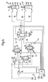
- the hydraulic and electrical control circuit of the vehicle roll control system of Figures 1 to 4 is shown in Figure 5.
- the hydraulic circuit includes a fluid pump 80, a fluid reservoir 81, a directional valve 82, a first pressure relief valve 83, a second pressure relief valve 84, a third pressure relief valve 85, and a pressure control valve 99.
- the directional valve 82 has six ports 87-92.
- the first pressure relief valve 83 has three ports 93-95.
- the second pressure relief valve 84 has three ports 96-98.
- the third pressure relief valve 85 has three ports 96'-98'.
- the pressure control valve 99 is fluidly connected between the pump 80 and the reservoir 81. Fluid filters may be positioned after the pump 80 and/or before the reservoir 81.
- the directional valve 82 has a first port 87 fluidly connected to the first port 93 of the first pressure relief valve 83; a second port 88 fluidly connected to the first port 96 of the second pressure relief valve 84; a third port 89 fluidly connected to the first port 96' of the third pressure relief valve 85; a fourth port 90 fluidly connected to the first chamber 58' of the rear actuator 34' by way of fluid line 66'; a fifth port 91 fluidly connected to the first chamber 58 of the front actuator 34 by way of fluid line 66; and a sixth port 92 fluidly connected to the second chambers 60, 60' of the front and rear actuators 34, 34' by way of fluid lines 68, 68'.
- the directional valve 82 is solenoid actuated, and has a de-actuated state (shown in Figure 5) in which the first, second, third and sixth ports 87-89, 92 are fluidly isolated from one another; and the fourth and fifth ports 90, 91 are fluidly connected.
- the first and sixth ports 87, 92 are fluidly connected; the second and fifth ports 88, 91 are fluidly connected; and the third and fourth ports 89, 90 are fluidly connected.
- the directional valve 82 may be hydraulically actuated by first and second pilot (on/off) valves (not shown).
- the second port 94 of the first pressure relief valve 83 is fluidly connected to the pump 80.
- the third port 95 of the first pressure relief valve 83 is fluidly connected to the reservoir 81.
- the first port 93 is fluidly connected to the third port 95, and the second port 94 is fluidly isolated.
- the first port 93 is fluidly connected to the second port 94, and the third port 95 is fluidly isolated.
- the second port 97 of the second pressure relief valve 84 is fluidly connected to the pump 80.
- the third port 98 of the second pressure relief valve 84 is fluidly connected to the reservoir 81.
- the first port 96 is fluidly connected to the third port 98, and the second port 97 is fluidly isolated.
- the first port 96 is fluidly connected to the second port 97, and the third port 98 is fluidly isolated.
- the second port 97' of the third pressure relief valve 85 is fluidly connected to the pump 80.
- the third port 98' of the third pressure relief valve 85 is fluidly connected to the reservoir 81.
- the first port 96' is fluidly connected to the third port 98', and the second port 97' is fluidly isolated.
- the first port 96' is fluidly connected to the second port 97', and the third port 98' is fluidly isolated.
- the first, second and third pressure relief valves 83, 84, 85 are preferably solenoid actuated as shown in Figure 5.
- the pressure relief valves 83, 84, 85 may be hydraulically actuated by first and second pilot (on/off) valves (not shown).
- the pump 80 may be driven by the vehicle engine and hence continuously actuated. Alternatively, the pump 80 may be driven by an electric motor or any other suitable means, either continuously, or variably.
- the pressure control valve 99 is actuated to adjust the fluid pressure in the hydraulic system between a predetermined minimum pressure and a predetermined maximum pressure.
- the pressure control valve 99 is also actuated to adjust the pressure differential between the first and second chambers 58, 58',60, 60' of the hydraulic actuators 34,34' respectively (when the directional valve 82 and pressure relief valves 83, 84, 85 are also actuated as required).
- the electrical control circuit includes an electronic and/or computerised control module 70.
- the control module 70 operates the fluid pump 80, the directional valve 82, the pressure control valve 99, and the pressure relief valves 83, 84, 85, when required.
- the control module 70 actuates the valves 82-85, 99 dependent on predetermined vehicle conditions which are determined by signals from one or more sensors, such as a first pressure sensor 76 (which detects the fluid pressure associated with the second chambers 60, 60' of the hydraulic actuators 34, 34'), a second pressure sensor 77 (which detects the fluid pressure associated with the first chamber 58 of the front hydraulic actuator 34), a third pressure sensor 75 (which detects the fluid pressure associated with the first chamber 58' of the rear hydraulic actuator 34'), a lateral g sensor 74 (which monitors the sideways acceleration of the vehicle), a steering sensor 72 (which monitors the steering angle of the front wheels 12), a vehicle speed sensor 78, and/or any other relevant parameter.
- sensors such as a first pressure sensor 76 (
- the control module 70 determines if the module has to generate a force F, F' which acts on the piston rods 64, 64' respectively to extend the front and/or rear actuators 34, 34', or to compress the front and/or rear actuators, in an axial direction.
- the force F on the front actuator 34 may be different from the force F' on the rear actuator 34' dependent on the actuation of the pressure relief valves 83, 84, 85; and the value of the pressure differential is set by the pressure control valve 99.
- the roll control system can be operated in a number of different modes when the directional valve 82 is actuated and the pressure control valve 99 is actuated.
- the various modes are determined by the actuation or de-actuation of the pressure relief valves 83, 84, 85.
- the first pressure relief valve 83 is actuated, and the second and third pressure relief valves 84, 85 are de-actuated.
- the first and third pressure relief valves 83, 85 are actuated.
- the first and second pressure relief valves 83, 84 are actuated.
- the second and third pressure relief valves 84, 85 are actuated and the first pressure relief valve 83 is de-actuated, with the pressure levels provided by valves 84 and 85 being adjusted respectively to provide the required bias.
- the value of any pressure differential is control by the pressure control valve 99 and the pressure relief valves 83, 84, 85, and the pressure from the pressure control valve 99 should be greater than or equal to the pressure from the pressure relief valves 83-85.
- the hydraulic circuit includes a fluid pump 480, a fluid reservoir 481, a directional valve 482, a first pressure relief valve 483, a second pressure relief valve 484, and a pressure control valve 499.
- the directional valve 482 has eight ports 485-492.
- the first pressure relief valve 483 has three ports 493-495.
- the second pressure relief valve 484 has three ports 496-498.
- the pressure control valve 499 is fluidly connected between the pump 480 and the reservoir 481. Fluid filters may be positioned after the pump 480 and/or before the reservoir 481.
- the directional valve 482 has a first port 485 fluidly connected to the fluid pump 480; a second port 486 fluidly connected to the first port 493 of the first pressure relief valve 483; a third port 487 and a fourth port 488 fluidly connected to the first port 496 of the second pressure relief valve 484; a fifth port 489 fluidly connected to the first chamber 58' of the rear actuator 34' by way of fluid line 66'; a sixth port 490 fluidly connected to the first chamber 58 of the front actuator 34 by way of fluid line 66; a seventh port 491 fluidly connected to the second chamber 60' of the rear actuator 34' by way of fluid line 68'; and an eighth port 492 fluidly connected to the second chamber 60 of the front actuator 34 by way of fluid line 68.
- the directional valve 482 is solenoid actuated, and has a de-actuated state (shown in Figure 6) in which all of the ports 485-492 are fluidly isolated.
- the first and eighth ports 485, 492 are fluidly connected; the second and seventh ports 486, 491 are fluidly connected; the third and sixth ports 487, 490 are fluidly connected; and the fourth and fifth ports 488, 489 are fluid connected.
- the directional valve 482 may be hydraulically actuated by first and second pilot (on/off) valves (not shown).
- the second port 494 of the first pressure relief valve 483 is fluidly connected to the pump 480.
- the third port 495 of the first pressure relief valve 483 is fluidly connected to the reservoir 481.
- the first port 493 is fluidly connected to the third port 495, and the second port 494 is fluidly isolated.
- the first port 493 is fluidly connected to the second port 494, and the third port 495 is fluidly isolated.
- the second port 497 of the second pressure relief valve 484 is fluidly connected to the pump 480.
- the third port 498 of the second pressure relief valve 484 is fluidly connected to the reservoir 481.
- the first port 496 is fluidly connected to the third port 498, and the second port 497 is fluidly isolated.
- the first port 496 is fluidly connected to the second port 497, and the third port 498 is fluidly isolated.
- the first and second pressure relief valves 483, 484 are preferably solenoid actuated as shown in Figure 6.
- the pressure relief valves 483, 484 may be hydraulically actuated by first and second pilot (on/off) valves (not shown).
- the pump 480 may be driven by the vehicle engine and hence continuously actuated. Alternatively, the pump 480 may be driven by an electric motor or any other suitable means, either continuously, or variably.
- the pressure control valve 499 is actuated to adjust the fluid pressure in the hydraulic system between a predetermined minimum pressure and a predetermined maximum pressure.
- the pressure control valve 499 is also actuated to adjust the pressure differential between the first and second chambers 58, 58',60, 60' of the hydraulic actuators 34,34' respectively (when the directional valve 482 and pressure relief valves 483, 484 are also actuated as required).
- the electrical control circuit includes an electronic and/or computerised control module 70.
- the control module 70 operates the fluid pump 480, the directional valve 482, the pressure control valve 499, and the pressure relief valves 483, 484, when required.
- the control module 70 actuates the valves 482-484, 499 dependent on predetermined vehicle conditions which are determined by signals from one or more sensors, such as a first pressure sensor 76 (which detects the fluid pressure associated with the second chamber 60' of the rear hydraulic actuator 34'), a second pressure sensor 77 (which detects the fluid pressure associated with the first chambers 58, 58' of the front and rear hydraulic actuators 34, 34'), a third pressure sensor 75 (which detects the fluid pressure associated with the second chamber 60 of the front actuator 34), a lateral g sensor 74 (which monitors the sideways acceleration of the vehicle), a steering sensor 72 (which monitors the steering angle of the front wheels 12), a vehicle speed sensor 78, and/or any other relevant parameter.
- sensors such as a first pressure sensor 76 (which
- the control module 70 determines if the module has to generate a force F, F' which acts on the piston rods 64, 64' respectively to extend the front and/or rear actuators 34, 34', or to compress the front and/or rear actuators, in an axial direction.
- the force F on the front actuator 34 may be different from the force F' on the rear actuator 34' dependent on the actuation of the pressure relief valves 483, 484; and the value of the pressure differential is set by the pressure control valve 499.
- the roll control system can be operated in different modes when the directional valve 482 is actuated and the pressure control valve 499 is actuated.
- the first pressure relief valve 483 is actuated and the second pressure relief valve 484 is de-actuated, with the first pressure relief valve 483 being adjusted to provide the required neutral or front bias.
- the first and second pressure relief valves 483, 484 are actuated.
- the first and second pressure relief valves 483, 484 are actuated, with the pressure levels provided by valves 483 and 484 being adjusted respectively to provide the required bias.
- the value of any pressure differential is control by the pressure control valve 499 and the pressure relief valves 483, 484 and the pressure from the pressure control valve 499 should be greater than or equal to the pressure from the pressure relief valves 483, 484.
- This arrangement provides improvement management of the compression or expansion of the hydraulic actuators, and hence provides improved roll control of the vehicle.
- the cross-sectional area of the first fluid chamber 58 of the front hydraulic actuator 34 described above is substantially double the cross-sectional area of the piston rod 64 of the hydraulic actuator, when considered on a radial basis, whereas the cross-sectional area of the first fluid chamber 58' of the rear hydraulic actuator 34' described above is not double the cross-sectional area of the piston rod 64' of the hydraulic actuator, when considered on a radial basis.
- Such an arrangement provides the same output force from the hydraulic actuator in either direction, using the same fluid pressure.
- valves of the hydraulic circuit are actuable to provide substantially the same fluid pressure to the first or second respective fluid chamber of each hydraulic actuator, whilst applying a different fluid pressure to the second or first respective fluid chamber of each hydraulic actuator.
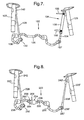
- the present invention is also applicable for use with a vehicle roll control system, the front portion 122 of which is as shown in Figure 7 and the rear portion of which is substantially identical to the front portion.
- the front portion 122 comprises a torsion bar 126, a first arm 128, and a hydraulic actuator 134.
- the first arm 128 is fixed at one end 138 to one end 140 of the torsion bar 126.
- the other end 142 of the first arm 128 is connected to one of the shock absorbers 120.
- the hydraulic actuator 134 has a piston rod 164 which is fixed to the other end 187 of the torsion bar 126.
- the housing 156 of the actuator 134 is connected to the other shock absorber 120.
- the hydraulic actuator 134 is substantially the same as the actuator 34 described above with reference to Figures 1 to 5, and has a fluid line 166 connected to a first fluid chamber inside the housing, and another fluid line 168 connected to a second fluid chamber inside the housing.
- the first and second fluid chambers inside the housing 156 are separated by a piston secured to the piston rod 164.
- the fluid lines 166,168 for each hydraulic actuator are connected to a hydraulic circuit as shown in Figure 5, which is controlled by a control circuit as shown in Figure 5, or the arrangement shown in Figure 6.
- the roll control system is operated in substantially the same manner as that described above with reference to Figures 1 to 5, or Figure 6.
- the front portion 222 of the system comprises a torsion bar 226, a first arm 228, a second arm 228', and a hydraulic actuator 234.
- the rear portion of the system is substantially identical.
- the first arm 228 is fixed at one end 238 to one end 240 of the torsion bar 226.
- the other end 242 of the first arm 228 is connected to one of the shock absorbers 220.
- the second arm 228' is fixed at one end 238' to the other end 287 of the torsion bar 226.
- the other end 242' of the second arm 228' is connected to the other shock absorber 220'.
- the torsion bar 226 is split into first and second parts 290,292, respectively.
- the first and second parts 290,292 of the torsion bar 226 have portions 294,296, respectively, which are axially aligned.
- the axially aligned portions 294,296 are connected by a hydraulic actuator 234.
- the hydraulic actuator 234 comprises a cylindrical housing 256 which is connected at one end 239 to the portion 294 of the first part 290 of the torsion bar 226.
- the actuator 234 further comprises a rod 241 positioned inside the housing 256, extending out of the other end 243 of the housing, and connectable to the portion 296 of the second part 292 of the torsion bar 226.
- the rod 241 has an external screw thread 249 adjacent the housing 256.
- Balls 251 are rotatably positioned in hemispherical indentations 253 in the inner surface 255 of the housing 256 adjacent the screw thread 249. The balls 251 extend into the screw thread 249.
- the rod 241 is slidably and rotatably mounted in the housing 256 at the other end 243 by way of a bearing 259 positioned in the other end 243. This arrangement allows the rod 241 to rotate about its longitudinal axis relative to the housing 256, and to slide in an axial direction A relative to the housing.
- a piston chamber 261 is defined inside the housing 256.
- the rod 241 sealing extends into the piston chamber 261 to define a piston rod 264, and a piston 262 is secured to the end of the piston rod inside the piston chamber.
- the piston 262 makes a sealing sliding fit with the housing 256 and divides the chamber 261 into a first fluid chamber 258 and a second fluid chamber 260.
- the first fluid chamber 258 is fluidly connected to fluid line 266, and the second fluid chamber 260 is fluidly connected to fluid line 268.
- the fluid lines 266,268 are connected to a hydraulic circuit as shown in Figure 5, which is controlled by a control circuit as shown in Figure 5, or the arrangement shown in Figure 6.
- the roll control system 222 is operated in substantially the same manner as that described above with reference to Figures 1 to 5, or Figure 6.
- the actuator 334 comprises a cylindrical housing 356 which is connected at one end 339 to the portion 294 of the first part 290 of the torsion bar 226.
- the actuator 334 further comprises a rod 341 positioned inside the housing 356, extending out of the other end 343 of the housing, and connectable to the portion 296 of the second part 292 of the torsion bar 226.
- the rod 341 has an external screw thread 349 adjacent the housing 356.
- Balls 351 are rotatably positioned in hemispherical indentations 353 in the inner surface 355 of the housing 356 adjacent the screw thread 349. The balls 351 extend into the screw thread 349.
- the rod 341 is slidably and rotatably mounted in the housing 356 at the other end 343 of the housing by way of a bearing 359 positioned in the other end.
- the rod 341 makes a sliding guiding fit with the inner surface 355 of the housing 356 at its end 341' remote from the second part 292 of the torsion bar 226. This arrangement allows the rod 341 to rotate about its longitudinal axis relative to the housing 356, and to slide in an axial direction A relative to the housing.
- First and second fluid chambers 358,360 are defined inside the housing 356.
- the rod 341 makes a sealing fit with the inner surface 355 of the housing 356 by way of seal 371 to define a piston 362.
- the first fluid chamber 358 is positioned on one side of the piston 362, and the second fluid chamber 360 is positioned on the other side of the piston.
- a seal 369 is positioned adjacent the bearing 359.
- a portion 364 of the rod 341 defines a piston rod which extends through the second fluid chamber 360.
- the first fluid chamber 358 is fluidly connected to fluid line 366, and the second fluid chamber 360 is fluidly connected to fluid line 368.
- the fluid lines 366,368 are fluidly connected with one of the hydraulic circuits shown in Figures 5 or 6 to actuate the actuator 334.
- FIG 11 A further alternative arrangement of hydraulic actuator 334' is shown in Figure 11.
- the actuator 334' is substantially the same as the actuator 334 shown in Figure 10, but without the sliding guiding fit of the free end 341' of the rod 341 with the housing 356.
- a hydraulic actuator is provided for both the front of the vehicle and the rear of the vehicle, and these hydraulic actuators are substantially the same.
- the hydraulic actuator for the front of the vehicle may be a different type to the hydraulic actuator for the rear of the vehicle.
- the hydraulic actuator may include a check valve (not shown, but preferably mounted in the piston) which allows flow of hydraulic fluid from the first fluid chamber to the second fluid chamber only when the fluid pressure in the first fluid chamber is greater than the fluid pressure in the second fluid chamber.
- the second fluid chamber can be connected to a reservoir during servicing of the actuator to bleed air from the hydraulic fluid.
- the presence of the check valve reduces the risk of air being sucked into the second fluid chamber should the fluid pressure in the second fluid chamber fall below the fluid pressure in the first fluid chamber, and provides further improvements in ride comfort.
Landscapes
- Engineering & Computer Science (AREA)
- Mechanical Engineering (AREA)
- Vehicle Body Suspensions (AREA)
Abstract
Description
- The present invention relates to a roll control system for a motor vehicle.
-
EP-A-1103395 discloses a vehicle roll control system in which a pair of directional valves and a pressure control valve are used to control the movement of the piston of hydraulic actuators associated with the front and rear axles of a motor vehicle.WO-A-03/093041 WO-A-2005/108128 discloses a roll control system in which the control means for the hydraulic circuit is capable of providing fluid pressure to the first fluid chamber of the front hydraulic actuator which is different from the fluid pressure provided to the first fluid chamber of the rear hydraulic actuator; and/or is capable of providing fluid pressure to the second fluid chamber of the front hydraulic actuator which is different from the fluid pressure provided to second fluid chamber of the rear hydraulic actuator. - The aim of the present invention is to provide a roll control system which is an improvement to the above mentioned arrangements.
- A vehicle roll control system in accordance with the present invention is characterised by the features specified in claim 1.
- In one embodiment of the present invention, the control means for the hydraulic circuit is capable of providing fluid pressure to the second fluid chamber of the front hydraulic actuator which is substantially the same as the fluid pressure provided to the second fluid chamber of the rear hydraulic actuator; and is capable of providing fluid pressure to the first fluid chamber of the front hydraulic actuator which is different from the fluid pressure provided to first fluid chamber of the rear hydraulic actuator.
- In another embodiment of the present invention, the control means for the hydraulic circuit is capable of providing fluid pressure to the second fluid chamber of the front hydraulic actuator which is different from the fluid pressure provided to the second fluid chamber of the rear hydraulic actuator; and is capable of providing fluid pressure to the first fluid chamber of the front hydraulic actuator which is substantially the same as the fluid pressure provided to first fluid chamber of the rear hydraulic actuator.
- The present invention provides a system which allows an aggressive roll control strategy and balance strategy which leads to improvements in motion, turning, and stability (braking in turn at high speed). The present invention also provides continuous control between right turn and left turn.
- The present invention will now be described, by way of example, with reference to the accompanying drawings, in which:-
- Figure 1 is a schematic presentation of a vehicle incorporating a vehicle roll control system in accordance with the present invention;
- Figure 2 is an enlarged view of the front and rear portions of the vehicle roll control system shown in Figure 1;
- Figure 3 is a side view of the first arm of the vehicle roll control system shown in Figure 2;
- Figure 4 is a side view of the second arm, hydraulic actuator (shown in cross-section) and lever arm of the vehicle roll control system shown in Figure 2;
- Figure 5 is a schematic diagram of the hydraulic and electrical control circuit of the vehicle roll control system shown in Figure 1 when the directional valve and pressure relief valves are de-actuated or in their fail-safe mode;
- Figure 6 is a schematic diagram of a first alternative hydraulic and electrical control circuit of the vehicle roll control system shown in Figure 1 when the directional valve and the pressure relief valves are de-actuated or in their fail-safe mode;
- Figure 7 is a view of a portion of a vehicle roll control system in accordance with a second embodiment of the present invention;
- Figure 8 is a view of a portion of a vehicle roll control system in accordance with a third embodiment of the present invention;
- Figure 9 is a cross-section view of the hydraulic actuator of the vehicle roll control system of Figure 8;
- Figure 10 is a cross-sectional view of an alternative embodiment of hydraulic actuator for the vehicle roll control system of Figure 8; and
- Figure 11 is a cross-sectional view of a further alternative embodiment of hydraulic actuator for the vehicle roll control system of Figure 8.
- Referring to Figure 1, a
vehicle 10 is shown schematically and comprises a pair offront wheels 12 each rotatably mounted on anaxle 14, a pair ofrear wheels 16 each rotatably mounted on anaxle 18, and ashock absorbing system 20 associated with each wheel. Aportion 22 of a vehicle roll control system in accordance with the present invention is associated with thefront wheels 12, and aportion 24 of the vehicle roll control system in accordance with the present invention is associated with therear wheels 16. Theportions vehicle 10. - Referring in more detail to Figures 2 to 4, the
portion 22 of the vehicle roll control system for the front of the vehicle comprises atorsion bar 26, afirst arm 28, asecond arm 30, alever arm 32, and ahydraulic actuator 34. Thetorsion bar 26 is mounted on the vehicle by a pair ofresilient mounts 36 in conventional manner to extend longitudinally between thewheels 12. The first arm 28 (Figure 3) is fixed at oneend 38 by asplined connection 40 to thetorsion bar 26. Theother end 42 of thefirst arm 28 is connected to theaxle 14 of one of thefront wheels 12 by atie rod 43. The second arm 30 (Figure 4) is rotatably mounted at oneend 44 on thetorsion bar 26 by way of abearing 46. Theother end 48 of thesecond arm 30 is connected to theaxle 14 of the otherfront wheel 12 by atie rod 49. The first andsecond arms torsion bar 26. - The lever arm 32 (Figure 4) is fixed at one
end 50 to thetorsion bar 26 by asplined connection 52 substantially adjacent the oneend 44 of thesecond arm 30 and thebearing 46. Thelever arm 32 extends substantially perpendicular to thetorsion bar 26 to afree end 54. The front hydraulic actuator 34 (Figure 4) extends between, and is connected to, thefree end 54 of thelever arm 32 and theother end 48 of thesecond arm 30. The fronthydraulic actuator 34 comprises ahousing 56 which defines first andsecond fluid chambers piston 62 which makes a sealing sliding fit with the housing. As shown in Figure 4, thehousing 56 is connected to theother end 48 of thesecond arm 30, and thepiston 62 is connected to thefree end 54 of thelever arm 32 by apiston rod 64 which extends through thesecond fluid chamber 60. It will be appreciated that these connections may be reversed. Thefluid chambers fluid lines portion 24 of the vehicle roll control for the rear of the vehicle is substantially the same, but with the components (which are primed) having a different layout. The rear hydraulic actuator 34' is substantially the same as the fronthydraulic actuator 34. - The hydraulic and electrical control circuit of the vehicle roll control system of Figures 1 to 4 is shown in Figure 5. The hydraulic circuit includes a
fluid pump 80, afluid reservoir 81, adirectional valve 82, a firstpressure relief valve 83, a secondpressure relief valve 84, a thirdpressure relief valve 85, and apressure control valve 99. Thedirectional valve 82 has six ports 87-92. The firstpressure relief valve 83 has three ports 93-95. The secondpressure relief valve 84 has three ports 96-98. The thirdpressure relief valve 85 has three ports 96'-98'. Thepressure control valve 99 is fluidly connected between thepump 80 and thereservoir 81. Fluid filters may be positioned after thepump 80 and/or before thereservoir 81. - The
directional valve 82 has afirst port 87 fluidly connected to thefirst port 93 of the firstpressure relief valve 83; asecond port 88 fluidly connected to thefirst port 96 of the secondpressure relief valve 84; athird port 89 fluidly connected to the first port 96' of the thirdpressure relief valve 85; afourth port 90 fluidly connected to the first chamber 58' of the rear actuator 34' by way of fluid line 66'; afifth port 91 fluidly connected to thefirst chamber 58 of thefront actuator 34 by way offluid line 66; and asixth port 92 fluidly connected to thesecond chambers 60, 60' of the front andrear actuators 34, 34' by way offluid lines 68, 68'. Thedirectional valve 82 is solenoid actuated, and has a de-actuated state (shown in Figure 5) in which the first, second, third and sixth ports 87-89, 92 are fluidly isolated from one another; and the fourth andfifth ports directional valve 82, the first andsixth ports fifth ports fourth ports directional valve 82 may be hydraulically actuated by first and second pilot (on/off) valves (not shown). - The
second port 94 of the firstpressure relief valve 83 is fluidly connected to thepump 80. Thethird port 95 of the firstpressure relief valve 83 is fluidly connected to thereservoir 81. In the de-actuated state of the first pressure relief valve 83 (shown in Figure 5), thefirst port 93 is fluidly connected to thethird port 95, and thesecond port 94 is fluidly isolated. In the actuated state of the firstpressure relief valve 83, thefirst port 93 is fluidly connected to thesecond port 94, and thethird port 95 is fluidly isolated. - The
second port 97 of the secondpressure relief valve 84 is fluidly connected to thepump 80. Thethird port 98 of the secondpressure relief valve 84 is fluidly connected to thereservoir 81. In the de-actuated state of the second pressure relief valve 84 (shown in Figure 5), thefirst port 96 is fluidly connected to thethird port 98, and thesecond port 97 is fluidly isolated. In the actuated state of the secondpressure relief valve 84, thefirst port 96 is fluidly connected to thesecond port 97, and thethird port 98 is fluidly isolated. - The second port 97' of the third
pressure relief valve 85 is fluidly connected to thepump 80. The third port 98' of the thirdpressure relief valve 85 is fluidly connected to thereservoir 81. In the de-actuated state of the third pressure relief valve 85 (shown in Figure 5), the first port 96' is fluidly connected to the third port 98', and the second port 97' is fluidly isolated. In the actuated state of the thirdpressure relief valve 85, the first port 96' is fluidly connected to the second port 97', and the third port 98' is fluidly isolated. - The first, second and third
pressure relief valves pressure relief valves - The
pump 80 may be driven by the vehicle engine and hence continuously actuated. Alternatively, thepump 80 may be driven by an electric motor or any other suitable means, either continuously, or variably. Thepressure control valve 99 is actuated to adjust the fluid pressure in the hydraulic system between a predetermined minimum pressure and a predetermined maximum pressure. Thepressure control valve 99 is also actuated to adjust the pressure differential between the first andsecond chambers hydraulic actuators 34,34' respectively (when thedirectional valve 82 andpressure relief valves - The electrical control circuit includes an electronic and/or
computerised control module 70. Thecontrol module 70 operates thefluid pump 80, thedirectional valve 82, thepressure control valve 99, and thepressure relief valves control module 70 actuates the valves 82-85, 99 dependent on predetermined vehicle conditions which are determined by signals from one or more sensors, such as a first pressure sensor 76 (which detects the fluid pressure associated with thesecond chambers 60, 60' of thehydraulic actuators 34, 34'), a second pressure sensor 77 (which detects the fluid pressure associated with thefirst chamber 58 of the front hydraulic actuator 34), a third pressure sensor 75 (which detects the fluid pressure associated with the first chamber 58' of the rear hydraulic actuator 34'), a lateral g sensor 74 (which monitors the sideways acceleration of the vehicle), a steering sensor 72 (which monitors the steering angle of the front wheels 12), avehicle speed sensor 78, and/or any other relevant parameter. - If the
control module 70 detects that roll control is required (due, for example, to cornering of the motor vehicle 10), the control module determines if the module has to generate a force F, F' which acts on thepiston rods 64, 64' respectively to extend the front and/orrear actuators 34, 34', or to compress the front and/or rear actuators, in an axial direction. In the present invention, the force F on thefront actuator 34 may be different from the force F' on the rear actuator 34' dependent on the actuation of thepressure relief valves pressure control valve 99. - In this arrangement, the roll control system can be operated in a number of different modes when the
directional valve 82 is actuated and thepressure control valve 99 is actuated. The various modes are determined by the actuation or de-actuation of thepressure relief valves actuators 34, 34' in compression, with a neutral bias, the firstpressure relief valve 83 is actuated, and the second and thirdpressure relief valves pressure relief valves pressure relief valves actuators 34, 34' in extension, for neutral, front or rear bias, the second and thirdpressure relief valves pressure relief valve 83 is de-actuated, with the pressure levels provided byvalves pressure control valve 99 and thepressure relief valves pressure control valve 99 should be greater than or equal to the pressure from the pressure relief valves 83-85. This arrangement provides improvement management of the compression or expansion of the hydraulic actuators, and hence provides improved roll control of the vehicle. - An alternative hydraulic and electrical control circuit of the vehicle roll control system of Figures 1 to 4 is shown in Figure 6. The hydraulic circuit includes a
fluid pump 480, afluid reservoir 481, adirectional valve 482, a firstpressure relief valve 483, a secondpressure relief valve 484, and apressure control valve 499. Thedirectional valve 482 has eight ports 485-492. The firstpressure relief valve 483 has three ports 493-495. The secondpressure relief valve 484 has three ports 496-498. Thepressure control valve 499 is fluidly connected between thepump 480 and thereservoir 481. Fluid filters may be positioned after thepump 480 and/or before thereservoir 481. - The
directional valve 482 has afirst port 485 fluidly connected to thefluid pump 480; asecond port 486 fluidly connected to thefirst port 493 of the firstpressure relief valve 483; athird port 487 and afourth port 488 fluidly connected to thefirst port 496 of the secondpressure relief valve 484; afifth port 489 fluidly connected to the first chamber 58' of the rear actuator 34' by way of fluid line 66'; asixth port 490 fluidly connected to thefirst chamber 58 of thefront actuator 34 by way offluid line 66; aseventh port 491 fluidly connected to the second chamber 60' of the rear actuator 34' by way of fluid line 68'; and aneighth port 492 fluidly connected to thesecond chamber 60 of thefront actuator 34 by way offluid line 68. Thedirectional valve 482 is solenoid actuated, and has a de-actuated state (shown in Figure 6) in which all of the ports 485-492 are fluidly isolated. In the actuated state of thedirectional valve 482, the first andeighth ports seventh ports sixth ports fifth ports directional valve 482 may be hydraulically actuated by first and second pilot (on/off) valves (not shown). - The
second port 494 of the firstpressure relief valve 483 is fluidly connected to thepump 480. Thethird port 495 of the firstpressure relief valve 483 is fluidly connected to thereservoir 481. In the de-actuated state of the first pressure relief valve 483 (shown in Figure 6), thefirst port 493 is fluidly connected to thethird port 495, and thesecond port 494 is fluidly isolated. In the actuated state of the firstpressure relief valve 483, thefirst port 493 is fluidly connected to thesecond port 494, and thethird port 495 is fluidly isolated. - The
second port 497 of the secondpressure relief valve 484 is fluidly connected to thepump 480. Thethird port 498 of the secondpressure relief valve 484 is fluidly connected to thereservoir 481. In the de-actuated state of the second pressure relief valve 484 (shown in Figure 6), thefirst port 496 is fluidly connected to thethird port 498, and thesecond port 497 is fluidly isolated. In the actuated state of the secondpressure relief valve 484, thefirst port 496 is fluidly connected to thesecond port 497, and thethird port 498 is fluidly isolated. - The first and second
pressure relief valves pressure relief valves - The
pump 480 may be driven by the vehicle engine and hence continuously actuated. Alternatively, thepump 480 may be driven by an electric motor or any other suitable means, either continuously, or variably. Thepressure control valve 499 is actuated to adjust the fluid pressure in the hydraulic system between a predetermined minimum pressure and a predetermined maximum pressure. Thepressure control valve 499 is also actuated to adjust the pressure differential between the first andsecond chambers hydraulic actuators 34,34' respectively (when thedirectional valve 482 andpressure relief valves - The electrical control circuit includes an electronic and/or
computerised control module 70. Thecontrol module 70 operates thefluid pump 480, thedirectional valve 482, thepressure control valve 499, and thepressure relief valves control module 70 actuates the valves 482-484, 499 dependent on predetermined vehicle conditions which are determined by signals from one or more sensors, such as a first pressure sensor 76 (which detects the fluid pressure associated with the second chamber 60' of the rear hydraulic actuator 34'), a second pressure sensor 77 (which detects the fluid pressure associated with thefirst chambers 58, 58' of the front and rearhydraulic actuators 34, 34'), a third pressure sensor 75 (which detects the fluid pressure associated with thesecond chamber 60 of the front actuator 34), a lateral g sensor 74 (which monitors the sideways acceleration of the vehicle), a steering sensor 72 (which monitors the steering angle of the front wheels 12), avehicle speed sensor 78, and/or any other relevant parameter. - If the
control module 70 detects that roll control is required (due, for example, to cornering of the motor vehicle 10), the control module determines if the module has to generate a force F, F' which acts on thepiston rods 64, 64' respectively to extend the front and/orrear actuators 34, 34', or to compress the front and/or rear actuators, in an axial direction. In the present invention, the force F on thefront actuator 34 may be different from the force F' on the rear actuator 34' dependent on the actuation of thepressure relief valves pressure control valve 499. - In the arrangement of Figure 6, the roll control system can be operated in different modes when the
directional valve 482 is actuated and thepressure control valve 499 is actuated. For example, foractuators 34, 34' in compression, for a neutral or front bias, the firstpressure relief valve 483 is actuated and the secondpressure relief valve 484 is de-actuated, with the firstpressure relief valve 483 being adjusted to provide the required neutral or front bias. For rear bias, the first and secondpressure relief valves actuators 34, 34' in extension, for neutral, front or rear bias, the first and secondpressure relief valves valves pressure control valve 499 and thepressure relief valves pressure control valve 499 should be greater than or equal to the pressure from thepressure relief valves - In a preferred arrangement of Figure 6, the cross-sectional area of the
first fluid chamber 58 of the fronthydraulic actuator 34 described above is substantially double the cross-sectional area of thepiston rod 64 of the hydraulic actuator, when considered on a radial basis, whereas the cross-sectional area of the first fluid chamber 58' of the rear hydraulic actuator 34' described above is not double the cross-sectional area of the piston rod 64' of the hydraulic actuator, when considered on a radial basis. Such an arrangement provides the same output force from the hydraulic actuator in either direction, using the same fluid pressure. - The above-described embodiments operate in substantially the same way, but provide different hydraulic circuit arrangements for their respective fail-safe modes, as illustrated in the drawings. Also, the selection is dependent on the type of hydraulic actuator that is used. Further, the connection of the front and rear actuators to the hydraulic circuit of Figure 5 or Figure 6 may be reversed.
- In the present invention, in the above embodiments, the valves of the hydraulic circuit are actuable to provide substantially the same fluid pressure to the first or second respective fluid chamber of each hydraulic actuator, whilst applying a different fluid pressure to the second or first respective fluid chamber of each hydraulic actuator.
- The present invention is also applicable for use with a vehicle roll control system, the
front portion 122 of which is as shown in Figure 7 and the rear portion of which is substantially identical to the front portion. In this embodiment in accordance with the present invention, thefront portion 122 comprises atorsion bar 126, afirst arm 128, and ahydraulic actuator 134. Thefirst arm 128 is fixed at oneend 138 to oneend 140 of thetorsion bar 126. Theother end 142 of thefirst arm 128 is connected to one of theshock absorbers 120. Thehydraulic actuator 134 has apiston rod 164 which is fixed to theother end 187 of thetorsion bar 126. Thehousing 156 of theactuator 134 is connected to theother shock absorber 120. Thehydraulic actuator 134 is substantially the same as theactuator 34 described above with reference to Figures 1 to 5, and has afluid line 166 connected to a first fluid chamber inside the housing, and anotherfluid line 168 connected to a second fluid chamber inside the housing. The first and second fluid chambers inside thehousing 156 are separated by a piston secured to thepiston rod 164. The fluid lines 166,168 for each hydraulic actuator are connected to a hydraulic circuit as shown in Figure 5, which is controlled by a control circuit as shown in Figure 5, or the arrangement shown in Figure 6. The roll control system is operated in substantially the same manner as that described above with reference to Figures 1 to 5, or Figure 6. - The present invention is also applicable for use with a vehicle roll control system as shown in Figure 8. In this third embodiment in accordance with the present invention, the
front portion 222 of the system comprises atorsion bar 226, afirst arm 228, a second arm 228', and ahydraulic actuator 234. The rear portion of the system is substantially identical. Thefirst arm 228 is fixed at oneend 238 to oneend 240 of thetorsion bar 226. Theother end 242 of thefirst arm 228 is connected to one of theshock absorbers 220. The second arm 228' is fixed at one end 238' to theother end 287 of thetorsion bar 226. The other end 242' of the second arm 228' is connected to the other shock absorber 220'. Thetorsion bar 226 is split into first and second parts 290,292, respectively. The first and second parts 290,292 of thetorsion bar 226 have portions 294,296, respectively, which are axially aligned. The axially aligned portions 294,296 are connected by ahydraulic actuator 234. - The
hydraulic actuator 234, as shown in Figure 9, comprises acylindrical housing 256 which is connected at oneend 239 to theportion 294 of thefirst part 290 of thetorsion bar 226. Theactuator 234 further comprises arod 241 positioned inside thehousing 256, extending out of theother end 243 of the housing, and connectable to theportion 296 of thesecond part 292 of thetorsion bar 226. Therod 241 has anexternal screw thread 249 adjacent thehousing 256.Balls 251 are rotatably positioned inhemispherical indentations 253 in theinner surface 255 of thehousing 256 adjacent thescrew thread 249. Theballs 251 extend into thescrew thread 249. Therod 241 is slidably and rotatably mounted in thehousing 256 at theother end 243 by way of abearing 259 positioned in theother end 243. This arrangement allows therod 241 to rotate about its longitudinal axis relative to thehousing 256, and to slide in an axial direction A relative to the housing. Apiston chamber 261 is defined inside thehousing 256. Therod 241 sealing extends into thepiston chamber 261 to define apiston rod 264, and apiston 262 is secured to the end of the piston rod inside the piston chamber. Thepiston 262 makes a sealing sliding fit with thehousing 256 and divides thechamber 261 into a firstfluid chamber 258 and a secondfluid chamber 260. The firstfluid chamber 258 is fluidly connected tofluid line 266, and the secondfluid chamber 260 is fluidly connected tofluid line 268. - The fluid lines 266,268 are connected to a hydraulic circuit as shown in Figure 5, which is controlled by a control circuit as shown in Figure 5, or the arrangement shown in Figure 6. The
roll control system 222 is operated in substantially the same manner as that described above with reference to Figures 1 to 5, or Figure 6. - An alternative arrangement for the hydraulic actuator of Figure 9 is shown in Figure 10. In this alternative embodiment, the
actuator 334 comprises acylindrical housing 356 which is connected at oneend 339 to theportion 294 of thefirst part 290 of thetorsion bar 226. Theactuator 334 further comprises arod 341 positioned inside thehousing 356, extending out of theother end 343 of the housing, and connectable to theportion 296 of thesecond part 292 of thetorsion bar 226. Therod 341 has anexternal screw thread 349 adjacent thehousing 356.Balls 351 are rotatably positioned inhemispherical indentations 353 in theinner surface 355 of thehousing 356 adjacent thescrew thread 349. Theballs 351 extend into thescrew thread 349. Therod 341 is slidably and rotatably mounted in thehousing 356 at theother end 343 of the housing by way of abearing 359 positioned in the other end. Therod 341 makes a sliding guiding fit with theinner surface 355 of thehousing 356 at its end 341' remote from thesecond part 292 of thetorsion bar 226. This arrangement allows therod 341 to rotate about its longitudinal axis relative to thehousing 356, and to slide in an axial direction A relative to the housing. First and second fluid chambers 358,360 are defined inside thehousing 356. Therod 341 makes a sealing fit with theinner surface 355 of thehousing 356 by way ofseal 371 to define apiston 362. The firstfluid chamber 358 is positioned on one side of thepiston 362, and the secondfluid chamber 360 is positioned on the other side of the piston. Aseal 369 is positioned adjacent thebearing 359. Aportion 364 of therod 341 defines a piston rod which extends through the secondfluid chamber 360. The firstfluid chamber 358 is fluidly connected tofluid line 366, and the secondfluid chamber 360 is fluidly connected tofluid line 368. The fluid lines 366,368 are fluidly connected with one of the hydraulic circuits shown in Figures 5 or 6 to actuate theactuator 334. - A further alternative arrangement of hydraulic actuator 334' is shown in Figure 11. In this further alternative embodiment, the actuator 334' is substantially the same as the
actuator 334 shown in Figure 10, but without the sliding guiding fit of the free end 341' of therod 341 with thehousing 356. - In the preferred arrangement described above, a hydraulic actuator is provided for both the front of the vehicle and the rear of the vehicle, and these hydraulic actuators are substantially the same. In an alternative arrangement, the hydraulic actuator for the front of the vehicle may be a different type to the hydraulic actuator for the rear of the vehicle.
- In any of the roll control systems described above, the hydraulic actuator may include a check valve (not shown, but preferably mounted in the piston) which allows flow of hydraulic fluid from the first fluid chamber to the second fluid chamber only when the fluid pressure in the first fluid chamber is greater than the fluid pressure in the second fluid chamber. With such an arrangement, the second fluid chamber can be connected to a reservoir during servicing of the actuator to bleed air from the hydraulic fluid. Also, the presence of the check valve reduces the risk of air being sucked into the second fluid chamber should the fluid pressure in the second fluid chamber fall below the fluid pressure in the first fluid chamber, and provides further improvements in ride comfort.
Claims (18)
- A vehicle roll control system for a vehicle having a pair of front wheels and a pair of rear wheels each rotatable on an axle, comprising a front torsion bar; a front first arm attached to the front torsion bar at one end of the front first arm and being connectable to one of the axles of the front wheels at the other end of the front first arm; a front hydraulic actuator attached to the front torsion bar; a rear torsion bar; a rear first arm attached to the rear torsion bar at one end of the rear first arm and being connectable to one of the axles of the rear wheels at the other end of the rear first arm; a rear hydraulic actuator attached to the rear torsion bar; and control means connected to the front and rear hydraulic actuators and controlling the operation thereof on detection of a predetermined vehicle condition; wherein each front and rear hydraulic actuator comprises a housing, a piston making a sealing sliding fit inside the housing to define a first fluid chamber and a second fluid chamber, and a piston rod connected to the piston and extending through the second fluid chamber and out of the housing; wherein the control means acts on detection of the predetermined vehicle condition to apply a fluid pressure to the first fluid chambers of the front and rear hydraulic actuators and to apply a fluid pressure to the second fluid chambers of the front and rear hydraulic actuators ; and wherein the control means comprises a source of fluid pressure, a fluid reservoir, a pressure control valve fluidly connected between the pressure source and the reservoir, a directional valve fluidly connected between the pressure control valve and the hydraulic actuators, and at least two pressure relief valves fluidly connecting the directional valve to the pressure source or the reservoir; wherein the pressure relief valves are actuated to create a pressure differential between the first fluid chambers whilst maintaining the second fluid chambers at substantially the same pressure or to create a pressure differential between the second fluid chambers whilst maintaining the first fluid chambers at substantially the same pressure.
- A vehicle roll control system as claimed in Claim 1 comprising first, second and third pressure relief valves, wherein the second fluid chambers of the front and rear actuators are fluidly connected together and fluidly connected to the pressure source or the reservoir by way of the first pressure relief valve; wherein the first fluid chamber of the front hydraulic actuator is fluidly connected to the pressure source or the reservoir by way of the second pressure relief valve; and wherein the first fluid chamber of the rear hydraulic actuator is fluidly connected to the pressure source or the reservoir by way of the third pressure relief valve.
- A vehicle roll control system as claimed in Claim 1 comprising first, second and third pressure relief valves, wherein the first fluid chambers of the front and rear actuators are fluidly connected together and fluidly connected to the pressure source or the reservoir by way of the first pressure relief valve; wherein the second fluid chamber of the front hydraulic actuator is fluidly connected to the pressure source or the reservoir by way of the second pressure relief valve; and wherein the second fluid chamber of the rear hydraulic actuator is fluidly connected to the pressure source or the reservoir by way of the third pressure relief valve.
- A vehicle roll control system as claimed in Claim 1 comprising first and second pressure relief valves, wherein the second fluid chamber of the rear hydraulic actuator is fluidly connected to the pressure source or the reservoir by way of the first pressure relief valve; and wherein the first fluid chambers of the front and rear actuators are fluidly connected together and to the pressure source or the reservoir by way of the second pressure relief valve.
- A vehicle roll control system as claimed in Claim 1 comprising first and second pressure relief valves, wherein the first fluid chamber of the rear hydraulic actuator is fluidly connected to the pressure source or the reservoir by way of the first pressure relief valve; and wherein the second fluid chambers of the front and rear actuators are fluidly connected together and to the pressure source or the reservoir by way of the second pressure relief valve.
- A vehicle roll control system as claimed in Claims 1 or Claim 2, wherein the directional valve, in its de-actuated state, fluidly connects the first fluid chambers to one another, and fluid isolates the second fluid chambers from one another and from the first fluid chambers.
- A vehicle roll control system as claimed in Claims 1 or Claim 3, wherein the directional valve, in its de-actuated state, fluidly connects the second fluid chambers to one another, and fluid isolates the first fluid chambers from one another and from the second fluid chambers.
- A vehicle roll control system as claimed in Claim 1 or Claim 4 or Claim 5, wherein the directional valve, in its de-actuated state, fluidly isolates the first fluid chambers from one another, and fluidly isolates the second fluid chambers from one another and from the first fluid chambers.
- A vehicle roll control system as claimed in any one of Claims 1 to 8, wherein the directional valve is actuated by a solenoid.
- A vehicle roll control system as claimed in any one of Claims 1 to 8, wherein the directional valve is hydraulic actuated by a pilot (on/off) valve.
- A vehicle roll control system as claimed in any one of Claims 1 to 10, wherein the control means further comprises an electronic control module which receives signals dependent on the predetermined vehicle condition, and which controls the position of the first and second directional valves.
- A vehicle roll control system as claimed in Claim 4 or Claim 5, wherein the cross-sectional area of the first fluid chamber of one of the actuator is substantially double the cross-sectional area of the piston rod of said one actuator.
- A vehicle roll control system as claimed in any one of Claims 1 to 12, wherein the front hydraulic actuator is attached to the front torsion bar at one end of the front hydraulic actuator and is connectable to the other axle of the front wheels at the other end of the front hydraulic actuator; and wherein the rear hydraulic actuator is attached to the rear torsion bar at one end of the rear hydraulic actuator and is connectable to the other axle of the rear wheels at the other end of the rear hydraulic actuator.
- A vehicle roll control system as claimed in Claim 13; further comprising a second front arm rotatably mounted on the front torsion bar at one end of the second front arm and being connectable to the other axle of the front wheels at the other end of the second front arm; wherein the front hydraulic actuator controls the rotation of the second front arm relative to the front torsion bar; and further comprising a second rear arm rotatably mounted on the rear torsion bar at one end of the second rear arm and being connectable to the other axle of the rear wheels at the other end of the second rear arm; wherein the rear hydraulic actuator controls the rotation of the second rear arm relative to the rear torsion bar.
- A vehicle roll control system as claimed in any one of Claims 1 to 12, wherein each hydraulic actuator is attached directly to its associated torsion bar at one end of the hydraulic actuator.
- A vehicle roll control system as claimed in any one of Claims 1 to 12, wherein each hydraulic actuator is attached to its associated torsion bar between axially aligned portions of first and second parts of the torsion bar.
- A vehicle roll control system as claimed in any one of Claims 1 to 16, wherein each hydraulic actuator includes a check valve which allows fluid to flow from the first fluid chamber to the second fluid chamber when the fluid pressure in the first fluid chamber exceeds the fluid pressure in the second fluid chamber.
- A vehicle roll control system as claimed in Claim 17, wherein the check valve is mounted in the piston.
Applications Claiming Priority (1)
| Application Number | Priority Date | Filing Date | Title |
|---|---|---|---|
| GBGB0618178.8A GB0618178D0 (en) | 2006-09-14 | 2006-09-14 | Vehicle roll control system |
Publications (3)
| Publication Number | Publication Date |
|---|---|
| EP1900555A2 true EP1900555A2 (en) | 2008-03-19 |
| EP1900555A3 EP1900555A3 (en) | 2010-03-03 |
| EP1900555B1 EP1900555B1 (en) | 2014-10-22 |
Family
ID=37309983
Family Applications (1)
| Application Number | Title | Priority Date | Filing Date |
|---|---|---|---|
| EP07075769.5A Ceased EP1900555B1 (en) | 2006-09-14 | 2007-09-07 | Vehicle roll control system |
Country Status (4)
| Country | Link |
|---|---|
| US (1) | US7694984B2 (en) |
| EP (1) | EP1900555B1 (en) |
| JP (1) | JP4685847B2 (en) |
| GB (1) | GB0618178D0 (en) |
Cited By (5)
| Publication number | Priority date | Publication date | Assignee | Title |
|---|---|---|---|---|
| EP2017101A1 (en) * | 2007-07-19 | 2009-01-21 | Delphi Technologies, Inc. | Vehicle roll control system |
| EP2017100A1 (en) * | 2007-07-19 | 2009-01-21 | Delphi Technologies, Inc. | Vehicle roll control system |
| WO2014153730A1 (en) * | 2013-03-27 | 2014-10-02 | Beijingwest Industries Co., Ltd. | Hydraulic suspension system |
| ES2550525A1 (en) * | 2014-05-08 | 2015-11-10 | Fº JAVIER PORRAS VILA | Electro-hydraulic system to balance the car when cornering (Machine-translation by Google Translate, not legally binding) |
| CN119459228A (en) * | 2024-12-24 | 2025-02-18 | 坐骑科技(安徽)有限公司 | Wheelbase adjustable two-wheel suspension and vehicle using the same |
Families Citing this family (6)
| Publication number | Priority date | Publication date | Assignee | Title |
|---|---|---|---|---|
| GB0410355D0 (en) * | 2004-05-10 | 2004-06-09 | Delphi Tech Inc | Vehicle roll control system |
| US7841608B2 (en) * | 2007-07-31 | 2010-11-30 | Hendrickson Usa, L.L.C. | Pneumatic proportioning system for vehicle air springs |
| CN101980878B (en) * | 2009-04-06 | 2012-12-12 | 丰田自动车株式会社 | Stabilizer device for vehicle |
| FR3067659B1 (en) * | 2017-06-14 | 2021-01-15 | Peugeot Citroen Automobiles Sa | ANTI-ROLLER DEVICE WITH PILOT COUPLING MEANS, FOR A MOTOR VEHICLE TRAIN |
| GB2597454B (en) * | 2020-07-21 | 2023-01-25 | Jaguar Land Rover Ltd | Active suspension system |
| DE102020129069A1 (en) | 2020-11-04 | 2022-05-05 | Muhr Und Bender Kg | Stabilizer assembly with actuator for a two-track vehicle |
Citations (3)
| Publication number | Priority date | Publication date | Assignee | Title |
|---|---|---|---|---|
| EP1103395A2 (en) | 1999-11-26 | 2001-05-30 | Delphi Technologies, Inc. | Vehicle roll control system |
| WO2003093041A1 (en) | 2002-05-02 | 2003-11-13 | Delphi Technologies, Inc. | Vehicle roll control system |
| WO2005108128A2 (en) | 2004-05-10 | 2005-11-17 | Delphi Technologies, Inc. | Vehicle roll control system |
Family Cites Families (8)
| Publication number | Priority date | Publication date | Assignee | Title |
|---|---|---|---|---|
| US5362094A (en) * | 1993-06-09 | 1994-11-08 | General Motors Corporation | Hydraulically controlled stabilizer bar system |
| US6929271B2 (en) * | 2001-11-09 | 2005-08-16 | Illinois Tool Works Inc. | Hydraulically compensated stabilizer system |
| WO2003101768A1 (en) * | 2002-05-31 | 2003-12-11 | Trw Automotive U.S. Llc | Integrated control unit for an active roll control system for a vehicle suspension system |
| WO2005072999A1 (en) * | 2004-01-28 | 2005-08-11 | Luk Lamellen Und Kupplungsbau Beteiligungs Kg | Active roll stabilization system |
| GB0410357D0 (en) * | 2004-05-10 | 2004-06-09 | Delphi Tech Inc | Vehicle roll control system |
| DE102004030009A1 (en) * | 2004-06-22 | 2006-01-12 | Hydac Electronic Gmbh | Hydraulic control device |
| DE102004058441A1 (en) * | 2004-12-03 | 2006-06-14 | Trw Automotive Gmbh | Active chassis stabilization system |
| US7487973B1 (en) * | 2005-08-24 | 2009-02-10 | Kelsey-Hayes Company | Multi-channel hydraulic control unit for an active vehicle suspension |
-
2006
- 2006-09-14 GB GBGB0618178.8A patent/GB0618178D0/en not_active Ceased
-
2007
- 2007-09-07 EP EP07075769.5A patent/EP1900555B1/en not_active Ceased
- 2007-09-13 US US11/900,862 patent/US7694984B2/en not_active Expired - Fee Related
- 2007-09-14 JP JP2007238689A patent/JP4685847B2/en not_active Expired - Fee Related
Patent Citations (3)
| Publication number | Priority date | Publication date | Assignee | Title |
|---|---|---|---|---|
| EP1103395A2 (en) | 1999-11-26 | 2001-05-30 | Delphi Technologies, Inc. | Vehicle roll control system |
| WO2003093041A1 (en) | 2002-05-02 | 2003-11-13 | Delphi Technologies, Inc. | Vehicle roll control system |
| WO2005108128A2 (en) | 2004-05-10 | 2005-11-17 | Delphi Technologies, Inc. | Vehicle roll control system |
Cited By (7)
| Publication number | Priority date | Publication date | Assignee | Title |
|---|---|---|---|---|
| EP2017101A1 (en) * | 2007-07-19 | 2009-01-21 | Delphi Technologies, Inc. | Vehicle roll control system |
| EP2017100A1 (en) * | 2007-07-19 | 2009-01-21 | Delphi Technologies, Inc. | Vehicle roll control system |
| WO2014153730A1 (en) * | 2013-03-27 | 2014-10-02 | Beijingwest Industries Co., Ltd. | Hydraulic suspension system |
| CN105142940A (en) * | 2013-03-27 | 2015-12-09 | 北京京西重工有限公司 | Hydraulic suspension system |
| US9579945B2 (en) | 2013-03-27 | 2017-02-28 | Beijingwest Industries Co., Ltd. | Hydraulic suspension system |
| ES2550525A1 (en) * | 2014-05-08 | 2015-11-10 | Fº JAVIER PORRAS VILA | Electro-hydraulic system to balance the car when cornering (Machine-translation by Google Translate, not legally binding) |
| CN119459228A (en) * | 2024-12-24 | 2025-02-18 | 坐骑科技(安徽)有限公司 | Wheelbase adjustable two-wheel suspension and vehicle using the same |
Also Published As
| Publication number | Publication date |
|---|---|
| EP1900555A3 (en) | 2010-03-03 |
| GB0618178D0 (en) | 2006-10-25 |
| EP1900555B1 (en) | 2014-10-22 |
| JP2008068859A (en) | 2008-03-27 |
| JP4685847B2 (en) | 2011-05-18 |
| US7694984B2 (en) | 2010-04-13 |
| US20080067863A1 (en) | 2008-03-20 |
Similar Documents
| Publication | Publication Date | Title |
|---|---|---|
| EP1900555B1 (en) | Vehicle roll control system | |
| EP1103396B1 (en) | Vehicle roll control system | |
| EP1503913B1 (en) | Vehicle roll control system | |
| US7862052B2 (en) | Vehicle roll control system | |
| EP1379399B1 (en) | Vehicle roll control system | |
| US7475895B2 (en) | Hydraulic circuit for a stabilizer bar | |
| US8065056B2 (en) | Vehicle roll control system | |
| EP2017101B1 (en) | Vehicle roll control system | |
| EP1902875B1 (en) | Hydraulic control circuit | |
| EP1747106A1 (en) | Vehicle roll control system | |
| GB2356606A (en) | Vehicle roll control system having an adjustable torsion bar |
Legal Events
| Date | Code | Title | Description |
|---|---|---|---|
| PUAI | Public reference made under article 153(3) epc to a published international application that has entered the european phase |
Free format text: ORIGINAL CODE: 0009012 |
|
| AK | Designated contracting states |
Kind code of ref document: A2 Designated state(s): AT BE BG CH CY CZ DE DK EE ES FI FR GB GR HU IE IS IT LI LT LU LV MC MT NL PL PT RO SE SI SK TR |
|
| AX | Request for extension of the european patent |
Extension state: AL BA HR MK YU |
|
| PUAL | Search report despatched |
Free format text: ORIGINAL CODE: 0009013 |
|
| AK | Designated contracting states |
Kind code of ref document: A3 Designated state(s): AT BE BG CH CY CZ DE DK EE ES FI FR GB GR HU IE IS IT LI LT LU LV MC MT NL PL PT RO SE SI SK TR |
|
| AX | Request for extension of the european patent |
Extension state: AL BA HR MK RS |
|
| 17P | Request for examination filed |
Effective date: 20100902 |
|
| AKX | Designation fees paid |
Designated state(s): DE FR GB |
|
| RAP1 | Party data changed (applicant data changed or rights of an application transferred) |
Owner name: BWI COMPANY LIMITED S.A. |
|
| 17Q | First examination report despatched |
Effective date: 20111215 |
|
| GRAP | Despatch of communication of intention to grant a patent |
Free format text: ORIGINAL CODE: EPIDOSNIGR1 |
|
| INTG | Intention to grant announced |
Effective date: 20140522 |
|
| GRAS | Grant fee paid |
Free format text: ORIGINAL CODE: EPIDOSNIGR3 |
|
| GRAA | (expected) grant |
Free format text: ORIGINAL CODE: 0009210 |
|
| AK | Designated contracting states |
Kind code of ref document: B1 Designated state(s): DE FR GB |
|
| REG | Reference to a national code |
Ref country code: GB Ref legal event code: FG4D |
|
| REG | Reference to a national code |
Ref country code: DE Ref legal event code: R096 Ref document number: 602007038958 Country of ref document: DE Effective date: 20141204 |
|
| REG | Reference to a national code |
Ref country code: DE Ref legal event code: R097 Ref document number: 602007038958 Country of ref document: DE |
|
| PLBE | No opposition filed within time limit |
Free format text: ORIGINAL CODE: 0009261 |
|
| STAA | Information on the status of an ep patent application or granted ep patent |
Free format text: STATUS: NO OPPOSITION FILED WITHIN TIME LIMIT |
|
| 26N | No opposition filed |
Effective date: 20150723 |
|
| REG | Reference to a national code |
Ref country code: FR Ref legal event code: PLFP Year of fee payment: 10 |
|
| REG | Reference to a national code |
Ref country code: FR Ref legal event code: PLFP Year of fee payment: 11 |
|
| REG | Reference to a national code |
Ref country code: FR Ref legal event code: PLFP Year of fee payment: 12 |
|
| PGFP | Annual fee paid to national office [announced via postgrant information from national office to epo] |
Ref country code: GB Payment date: 20220804 Year of fee payment: 16 Ref country code: DE Payment date: 20220803 Year of fee payment: 16 |
|
| PGFP | Annual fee paid to national office [announced via postgrant information from national office to epo] |
Ref country code: FR Payment date: 20220808 Year of fee payment: 16 |
|
| REG | Reference to a national code |
Ref country code: DE Ref legal event code: R119 Ref document number: 602007038958 Country of ref document: DE |
|
| GBPC | Gb: european patent ceased through non-payment of renewal fee |
Effective date: 20230907 |
|
| PG25 | Lapsed in a contracting state [announced via postgrant information from national office to epo] |
Ref country code: GB Free format text: LAPSE BECAUSE OF NON-PAYMENT OF DUE FEES Effective date: 20230907 |
|
| PG25 | Lapsed in a contracting state [announced via postgrant information from national office to epo] |
Ref country code: GB Free format text: LAPSE BECAUSE OF NON-PAYMENT OF DUE FEES Effective date: 20230907 Ref country code: FR Free format text: LAPSE BECAUSE OF NON-PAYMENT OF DUE FEES Effective date: 20230930 Ref country code: DE Free format text: LAPSE BECAUSE OF NON-PAYMENT OF DUE FEES Effective date: 20240403 |