EP1900545A1 - Aircraft wheel noise reduction fairing and aircraft wheel including a noise reduction fairing - Google Patents
Aircraft wheel noise reduction fairing and aircraft wheel including a noise reduction fairing Download PDFInfo
- Publication number
- EP1900545A1 EP1900545A1 EP07116373A EP07116373A EP1900545A1 EP 1900545 A1 EP1900545 A1 EP 1900545A1 EP 07116373 A EP07116373 A EP 07116373A EP 07116373 A EP07116373 A EP 07116373A EP 1900545 A1 EP1900545 A1 EP 1900545A1
- Authority
- EP
- European Patent Office
- Prior art keywords
- noise reduction
- aircraft wheel
- fairing
- reduction fairing
- mesh
- Prior art date
- Legal status (The legal status is an assumption and is not a legal conclusion. Google has not performed a legal analysis and makes no representation as to the accuracy of the status listed.)
- Granted
Links
- 239000000463 material Substances 0.000 claims description 3
- 229910052751 metal Inorganic materials 0.000 description 5
- 239000002184 metal Substances 0.000 description 5
- 238000001816 cooling Methods 0.000 description 4
- 238000007689 inspection Methods 0.000 description 3
- 239000004033 plastic Substances 0.000 description 3
- 229920003023 plastic Polymers 0.000 description 3
- 238000007792 addition Methods 0.000 description 2
- 239000000853 adhesive Substances 0.000 description 2
- 230000001070 adhesive effect Effects 0.000 description 2
- 150000002739 metals Chemical class 0.000 description 2
- 238000012986 modification Methods 0.000 description 2
- 230000004048 modification Effects 0.000 description 2
- 229910000831 Steel Inorganic materials 0.000 description 1
- 230000002411 adverse Effects 0.000 description 1
- 229910052782 aluminium Inorganic materials 0.000 description 1
- XAGFODPZIPBFFR-UHFFFAOYSA-N aluminium Chemical compound [Al] XAGFODPZIPBFFR-UHFFFAOYSA-N 0.000 description 1
- 230000009286 beneficial effect Effects 0.000 description 1
- 230000007613 environmental effect Effects 0.000 description 1
- 239000007769 metal material Substances 0.000 description 1
- 239000010959 steel Substances 0.000 description 1
- 238000003466 welding Methods 0.000 description 1
Images

Classifications
-
- B—PERFORMING OPERATIONS; TRANSPORTING
- B60—VEHICLES IN GENERAL
- B60B—VEHICLE WHEELS; CASTORS; AXLES FOR WHEELS OR CASTORS; INCREASING WHEEL ADHESION
- B60B7/00—Wheel cover discs, rings, or the like, for ornamenting, protecting, venting, or obscuring, wholly or in part, the wheel body, rim, hub, or tyre sidewall, e.g. wheel cover discs, wheel cover discs with cooling fins
- B60B7/06—Fastening arrangements therefor
- B60B7/14—Fastening arrangements therefor comprising screw-threaded means
-
- B—PERFORMING OPERATIONS; TRANSPORTING
- B60—VEHICLES IN GENERAL
- B60B—VEHICLE WHEELS; CASTORS; AXLES FOR WHEELS OR CASTORS; INCREASING WHEEL ADHESION
- B60B7/00—Wheel cover discs, rings, or the like, for ornamenting, protecting, venting, or obscuring, wholly or in part, the wheel body, rim, hub, or tyre sidewall, e.g. wheel cover discs, wheel cover discs with cooling fins
- B60B7/04—Wheel cover discs, rings, or the like, for ornamenting, protecting, venting, or obscuring, wholly or in part, the wheel body, rim, hub, or tyre sidewall, e.g. wheel cover discs, wheel cover discs with cooling fins built-up of several main parts
-
- B—PERFORMING OPERATIONS; TRANSPORTING
- B60—VEHICLES IN GENERAL
- B60B—VEHICLE WHEELS; CASTORS; AXLES FOR WHEELS OR CASTORS; INCREASING WHEEL ADHESION
- B60B7/00—Wheel cover discs, rings, or the like, for ornamenting, protecting, venting, or obscuring, wholly or in part, the wheel body, rim, hub, or tyre sidewall, e.g. wheel cover discs, wheel cover discs with cooling fins
- B60B7/06—Fastening arrangements therefor
- B60B7/061—Fastening arrangements therefor characterised by the part of the wheels to which the discs, rings or the like are mounted
- B60B7/066—Fastening arrangements therefor characterised by the part of the wheels to which the discs, rings or the like are mounted to the hub
-
- B—PERFORMING OPERATIONS; TRANSPORTING
- B64—AIRCRAFT; AVIATION; COSMONAUTICS
- B64C—AEROPLANES; HELICOPTERS
- B64C25/00—Alighting gear
- B64C25/001—Devices not provided for in the groups B64C25/02 - B64C25/68
- B64C2025/003—Means for reducing landing gear noise, or turbulent flow around it, e.g. landing gear doors used as deflectors
Definitions
- the present invention is directed to an aircraft wheel noise reduction fairing and to an aircraft wheel on which a noise reduction fairing is mounted, and, more specifically, toward an aircraft wheel noise reduction fairing having a plurality of circumferentially disposed openings and to an aircraft wheel having a plurality of bolt holes on which a noise reduction fairing having a plurality of circumferentially disposed openings is mounted.
- Aircraft produce significant environmental noise, particularly during take-off and landing. This noise is produced by the aircraft engines, by generators and other aircraft systems, and by air flowing over an aircraft. These noises combine to produce the overall "noise signature" of an aircraft. It is generally desirable to reduce the noise signature of aircraft, especially when they take off and land at airports near populated areas.
- Airflow past aircraft wheels also plays a role in cooling aircraft brakes. It may be possible to reduce an aircraft noise signature by directing flowing air away from the wheels and brakes. However, if no air reaches the brakes, they may overheat and be damaged. Care must also be taken to ensure that the airflow redirecting structures do not themselves have an objectionable noise signature. It would be beneficial to provide an arrangement for reducing the component of an aircraft noise signature caused by the landing gear and wheels without adversely affecting brake cooling.
- a first aspect of which comprises an aircraft wheel noise reduction fairing that includes a disk having a first side and a second side and a plurality of circumferentially disposed openings between the first side and the second side. At least one mesh structure is connected to the second side of the disk and overlies the plurality of circumferentially disposed openings.
- Another aspect of the invention comprises an aircraft wheel that includes a hub surrounding the wheel axis of rotation, a web projecting from the hub, and a cylindrical wall spaced from the hub, connected to the web and surrounding the axis of rotation.
- the cylindrical wall has an inner surface and an outer surface and an end edge spaced from the web.
- a noise reduction fairing including a plurality of circumferentially disposed openings is mounted in the cylindrical space defined by the cylindrical wall.
- Fig. 1 is front plan view of an aircraft wheel noise reduction fairing according to an embodiment of the present invention
- Fig. 2 is a rear plan view of the aircraft wheel noise reduction fairing of Fig. 1;
- Fig. 3 is a sectional elevation view taken along line III-III in Fig. 1;
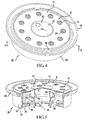
- Fig. 4 is a perspective view of the aircraft wheel noise reduction fairing of Fig. 1 attached to an outboard half of an aircraft wheel;
- Fig. 5 is a sectional perspective view taken along line V-V of Fig. 4.
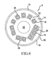
- Fig. 6 is a rear plan view of the fairing of Fig. 1 using an alternate arrangement of mesh over openings in the fairing.
- Figure 1 illustrates an aircraft wheel noise reduction fairing 8 comprising an annular disk-shaped body 10 having a first side 12, a second side 14 (illustrated in Fig. 2) a plurality of circumferentially disposed openings 16 between first side 12 and second side 14, and an outer periphery 18.
- Fairing body 10 is generally planar but may include a central portion 20 that is slightly convex to conform to the shape of a hubcap 50 to which it may be attached as described herein. Central portion 20 is surrounded by an annular, planar region 22 in which openings 16 are formed.
- fairing 8 also includes a mesh ring 24 on second side 14 of body 10 overlying the plurality of openings 16 and connected to second side 14.
- Fairing body 8 is preferably formed from a metal such as aluminum or steel, but may alternately be formed from various known plastics.
- Mesh ring 24 is also preferably formed from a metal mesh, such as a wire or expanded metal mesh but may alternately be fabricated from a suitable plastic or other non-metallic material.
- Mesh ring 24 may be attached to fairing body 10 in any manner suitable to the materials from which the fairing body 10 and mesh ring 24 are formed. For example, welding may be used when both elements are formed from appropriate metals and suitable adhesives may be used when the elements are formed form metals or common plastics.
- a continuous mesh ring 24 is illustrated in Figure 2, individual mesh panels 26, illustrated in Figure 6, covering individuals or several adjacent openings 16 could alternately be used.
- fairing 8 is illustrated mounted on the outboard half of an aircraft wheel 30.
- Wheel 30 includes a hub 32 around a wheel axis of rotation 34, a web 36 projecting from hub 32 generally normal to the axis of rotation 34 and including a plurality of tie bolt holes 38, a cylindrical wall 40 concentric with hub 32 and having an inner surface 42, an outer surface 44, and an end edge 46.
- a flange 48 forms a rim of wheel 20 and projects from the outer surface 44 of cylindrical wall 40 at a small distance from end edge 46.
- a hubcap 50 may be attached to hub 32 as illustrated in Fig. 5. In use, a tire (not illustrated) would be attached over surface 44 and be held in place by flange 48.
- fairing 8 is connected to wheel 20 by attaching fairing body 10 to hubcap 50 using a plurality of screws or similar fasteners 52. While it is preferable to use removable fasteners 52 such as screws so that fairing 8 can be removed to allow access to tie bolts (not illustrated) extending thorough holes 38 in web 36 and the inflation valve (not illustrated) in the web 36, suitable adhesives may be used between central portion 20 of fairing body 10 and hubcap 50 and/or between outer periphery 18 and inner surface 42 of cylindrical wall 40 to provide more secure attachment.
- Fairing 8 is mounted in the opening defined by inner surface 42 of cylindrical wall 40 and substantially closes this opening and covers hub 32.
- the fairing body 10 is mounted in the opening flush with or at a small distance inwardly from end edge 46 and does not project beyond the plane in which end edge 46 lies.
- fairing body 10 has a diameter less than the diameter of the opening defined by inner surface 42.
- a flexible material 60 such as a rubber gasket may be used to fill the gap between the outer edge 18 of fairing body 10 and the inner wall 42 of web 40. This reduces the noise signature of the fairing.
- openings 16 provide air flow and allow adequate cooling for brakes and wheels.
- openings 16 allow for the inspection of tie bolts (not shown) which extend through holes 38 in web 36 without the need to remove fairing 8. It is generally desirable for one opening 16 to be aligned with or otherwise provide visibility to each hole 38 to provide for easy inspection of tie bolts.
- openings 16 may adequately reduce the noise signature of aircraft landing gear provided with such a fairing. However, the openings 16 themselves will also contribute to the noise signature of an aircraft on which fairing 8 is mounted. It therefore may be desirable to use mesh ring 24 (Fig. 2) or individual mesh patches 26 (Fig. 6) to cover some or all openings 16 in order to reduce the noise signature of openings 16. Mesh ring 24 or mesh patches 26 should thus reduce the noise signature of openings 16 while still allowing tie bolt inspection and air flow for cooling.
Landscapes
- Engineering & Computer Science (AREA)
- Mechanical Engineering (AREA)
- Laminated Bodies (AREA)
Abstract
Description
- The present invention is directed to an aircraft wheel noise reduction fairing and to an aircraft wheel on which a noise reduction fairing is mounted, and, more specifically, toward an aircraft wheel noise reduction fairing having a plurality of circumferentially disposed openings and to an aircraft wheel having a plurality of bolt holes on which a noise reduction fairing having a plurality of circumferentially disposed openings is mounted.
- Aircraft produce significant environmental noise, particularly during take-off and landing. This noise is produced by the aircraft engines, by generators and other aircraft systems, and by air flowing over an aircraft. These noises combine to produce the overall "noise signature" of an aircraft. It is generally desirable to reduce the noise signature of aircraft, especially when they take off and land at airports near populated areas.
- Noise produced by air flowing past the landing gear, in particular the wheels and brakes of an aircraft, is a noticeable component of the noise signature of many aircraft. Airflow past aircraft wheels also plays a role in cooling aircraft brakes. It may be possible to reduce an aircraft noise signature by directing flowing air away from the wheels and brakes. However, if no air reaches the brakes, they may overheat and be damaged. Care must also be taken to ensure that the airflow redirecting structures do not themselves have an objectionable noise signature. It would be beneficial to provide an arrangement for reducing the component of an aircraft noise signature caused by the landing gear and wheels without adversely affecting brake cooling.
- These problems and others are addressed by the present invention, a first aspect of which comprises an aircraft wheel noise reduction fairing that includes a disk having a first side and a second side and a plurality of circumferentially disposed openings between the first side and the second side. At least one mesh structure is connected to the second side of the disk and overlies the plurality of circumferentially disposed openings.
- Another aspect of the invention comprises an aircraft wheel that includes a hub surrounding the wheel axis of rotation, a web projecting from the hub, and a cylindrical wall spaced from the hub, connected to the web and surrounding the axis of rotation. The cylindrical wall has an inner surface and an outer surface and an end edge spaced from the web. A noise reduction fairing including a plurality of circumferentially disposed openings is mounted in the cylindrical space defined by the cylindrical wall.
- These and other aspects and features of embodiments of the present invention will be better understood after a reading of the following detailed description together with the attached drawings, wherein:
- Fig. 1 is front plan view of an aircraft wheel noise reduction fairing according to an embodiment of the present invention;
- Fig. 2 is a rear plan view of the aircraft wheel noise reduction fairing of Fig. 1;
- Fig. 3 is a sectional elevation view taken along line III-III in Fig. 1;
- Fig. 4 is a perspective view of the aircraft wheel noise reduction fairing of Fig. 1 attached to an outboard half of an aircraft wheel;
- Fig. 5 is a sectional perspective view taken along line V-V of Fig. 4; and
- Fig. 6 is a rear plan view of the fairing of Fig. 1 using an alternate arrangement of mesh over openings in the fairing.
- Referring now to the drawings, wherein the showings are for purposes of illustrating presently preferred embodiments of the invention only and not for the purpose of limiting same, Figure 1 illustrates an aircraft wheel
noise reduction fairing 8 comprising an annular disk-shaped body 10 having afirst side 12, a second side 14 (illustrated in Fig. 2) a plurality of circumferentially disposedopenings 16 betweenfirst side 12 andsecond side 14, and anouter periphery 18.Fairing body 10 is generally planar but may include acentral portion 20 that is slightly convex to conform to the shape of ahubcap 50 to which it may be attached as described herein.Central portion 20 is surrounded by an annular,planar region 22 in whichopenings 16 are formed. - As best illustrated in Figure 2,
fairing 8 also includes amesh ring 24 onsecond side 14 ofbody 10 overlying the plurality ofopenings 16 and connected tosecond side 14.Fairing body 8 is preferably formed from a metal such as aluminum or steel, but may alternately be formed from various known plastics.Mesh ring 24 is also preferably formed from a metal mesh, such as a wire or expanded metal mesh but may alternately be fabricated from a suitable plastic or other non-metallic material.Mesh ring 24 may be attached to fairingbody 10 in any manner suitable to the materials from which thefairing body 10 andmesh ring 24 are formed. For example, welding may be used when both elements are formed from appropriate metals and suitable adhesives may be used when the elements are formed form metals or common plastics. And, while acontinuous mesh ring 24 is illustrated in Figure 2,individual mesh panels 26, illustrated in Figure 6, covering individuals or severaladjacent openings 16 could alternately be used. - In Figures 4 and 5,
fairing 8 is illustrated mounted on the outboard half of anaircraft wheel 30.Wheel 30 includes ahub 32 around a wheel axis ofrotation 34, aweb 36 projecting fromhub 32 generally normal to the axis ofrotation 34 and including a plurality oftie bolt holes 38, acylindrical wall 40 concentric withhub 32 and having aninner surface 42, anouter surface 44, and anend edge 46. Aflange 48 forms a rim ofwheel 20 and projects from theouter surface 44 ofcylindrical wall 40 at a small distance fromend edge 46. Ahubcap 50 may be attached tohub 32 as illustrated in Fig. 5. In use, a tire (not illustrated) would be attached oversurface 44 and be held in place byflange 48. - In a disclosed embodiment,
fairing 8 is connected towheel 20 by attachingfairing body 10 to hubcap 50 using a plurality of screws orsimilar fasteners 52. While it is preferable to useremovable fasteners 52 such as screws so thatfairing 8 can be removed to allow access to tie bolts (not illustrated) extendingthorough holes 38 inweb 36 and the inflation valve (not illustrated) in theweb 36, suitable adhesives may be used betweencentral portion 20 offairing body 10 andhubcap 50 and/or betweenouter periphery 18 andinner surface 42 ofcylindrical wall 40 to provide more secure attachment. -
Fairing 8 is mounted in the opening defined byinner surface 42 ofcylindrical wall 40 and substantially closes this opening and covershub 32. In the disclosed embodiment, thefairing body 10 is mounted in the opening flush with or at a small distance inwardly fromend edge 46 and does not project beyond the plane in whichend edge 46 lies. In this embodiment,fairing body 10 has a diameter less than the diameter of the opening defined byinner surface 42. Aflexible material 60 such as a rubber gasket may be used to fill the gap between theouter edge 18 offairing body 10 and theinner wall 42 ofweb 40. This reduces the noise signature of the fairing. - While a fairing without openings might provide a smaller noise signature than the disclosed
fairing 8, such a fairing would interfere substantially with air flow tohub 32,web 36 and to brakes (not illustrated) which would typically be mounted on the side ofweb 36opposite fairing 8.Openings 16 provide air flow and allow adequate cooling for brakes and wheels. In addition,openings 16 allow for the inspection of tie bolts (not shown) which extend throughholes 38 inweb 36 without the need to removefairing 8. It is generally desirable for one opening 16 to be aligned with or otherwise provide visibility to eachhole 38 to provide for easy inspection of tie bolts. - It is believed that
openings 16 may adequately reduce the noise signature of aircraft landing gear provided with such a fairing. However, theopenings 16 themselves will also contribute to the noise signature of an aircraft on whichfairing 8 is mounted. It therefore may be desirable to use mesh ring 24 (Fig. 2) or individual mesh patches 26 (Fig. 6) to cover some or allopenings 16 in order to reduce the noise signature ofopenings 16. Meshring 24 ormesh patches 26 should thus reduce the noise signature ofopenings 16 while still allowing tie bolt inspection and air flow for cooling. - The present invention has been described herein in terms of several preferred embodiments. Obvious additions and modifications to these embodiments will become apparent to those of ordinary skill in the relevant art upon review of the foregoing description. It is intended that all such obvious modifications and additions form a part of the present invention to the extent they fall within the scope of the several claims appended hereto.
Claims (10)
- An aircraft wheel noise reduction fairing (8) comprising:a disk (10) having a first side (12) and a second side (14) and a plurality of circumferentially disposed openings (16) between said first side (12) and said second side (14); andat least one mesh structure (24, 26) connected to the second side (14) of the disk (10) and overlying the plurality of circumferentially disposed openings (16).
- The aircraft wheel noise reduction fairing (8) of claim 1 wherein said disk (10) comprises a planar annular portion (22) surrounding a convex portion (20) and wherein said plurality of circumferentially disposed openings (16) are formed in said annular portion (22).
- An aircraft wheel (30) comprising the aircraft wheel noise reduction fairing (8) of claim 1.
- The aircraft wheel noise reduction fairing (8) of claim 1 wherein said at least one mesh structure comprises a mesh ring (24) or multiple mesh segments (26).
- An aircraft wheel (30) comprising:a hub (32) surrounding a wheel axis of rotation (34);a web (36) projecting from said hub (32);a cylindrical wall (40) spaced from said hub (32), connected to said web (36) and surrounding said axis of rotation (34), said cylindrical wall (40) having an inner surface (42) and an outer surface (44) and an end edge (46) spaced from said web (36);a flange (48) spaced from said end edge (46) and projecting from said cylindrical wall (40) away from said hub (32); anda noise reduction fairing (8) comprising a disk (10) having a first side (12) and a second side (14) and a plurality of circumferentially disposed openings (16) between said first side (12) and said second side (14) mounted in the cylindrical space defined by said cylindrical wall (40).
- The aircraft wheel (30) of claim 5 wherein said aircraft wheel (30) includes a hub cap (50) between said noise reduction fairing (8) and said hub (32) and at least one fastener (52) connecting said noise reduction fairing (8) to said hub cap (50).
- The aircraft wheel (30) of claim 5 wherein said noise reduction fairing (8) includes a central portion (20) conforming to a shape of the hubcap (50) and an annular, planar, outer portion (22).
- The aircraft wheel (30) of claim 5 wherein said end edge (46) lies in a plane and said fairing (8) lies entirely to one side of said plane.
- The aircraft wheel (30) of claim 5 including a mesh (24, 26) covering at least some of said annular openings (16), the mesh (24, 26) comprising an annular band of mesh (24) or individual mesh segments (26) covering each of said plurality of circumferential openings (16), the mesh (24, 26) being mounted on the side (14) of said noise reduction fairing (8) facing said web (36).
- The aircraft wheel (30) of claim 5 wherein said noise reduction fairing (8) has a diameter less than the diameter of said cylindrical space defined by said cylindrical wall (40) and includes a flexible material (60) filling a gap between said noise reduction fairing (8) and said cylindrical wall (40).
Applications Claiming Priority (1)
| Application Number | Priority Date | Filing Date | Title |
|---|---|---|---|
| US11/521,432 US20080078866A1 (en) | 2006-09-15 | 2006-09-15 | Aircraft wheel noise reduction fairing and aircraft wheel including a noise reduction fairing |
Publications (2)
| Publication Number | Publication Date |
|---|---|
| EP1900545A1 true EP1900545A1 (en) | 2008-03-19 |
| EP1900545B1 EP1900545B1 (en) | 2009-09-09 |
Family
ID=38707223
Family Applications (1)
| Application Number | Title | Priority Date | Filing Date |
|---|---|---|---|
| EP07116373A Withdrawn - After Issue EP1900545B1 (en) | 2006-09-15 | 2007-09-13 | Aircraft wheel noise reduction fairing and aircraft wheel including a noise reduction fairing |
Country Status (3)
| Country | Link |
|---|---|
| US (1) | US20080078866A1 (en) |
| EP (1) | EP1900545B1 (en) |
| DE (1) | DE602007002351D1 (en) |
Cited By (2)
| Publication number | Priority date | Publication date | Assignee | Title |
|---|---|---|---|---|
| WO2010119109A1 (en) * | 2009-04-16 | 2010-10-21 | Messier-Dowty Sa | Device for reducing the aerodynamic noise of an aircraft landing gear |
| EP3560826A1 (en) * | 2018-04-25 | 2019-10-30 | Safran Landing Systems UK Limited | Noise reduction fairing |
Families Citing this family (2)
| Publication number | Priority date | Publication date | Assignee | Title |
|---|---|---|---|---|
| US20160031498A1 (en) * | 2015-10-16 | 2016-02-04 | Caterpillar Inc. | Method for reducing noise from an idler wheel |
| FR3112580B1 (en) * | 2020-07-20 | 2022-07-22 | Safran Ventilation Systems | Ventilation system for an aircraft wheel and wheel assembly comprising such a system |
Citations (4)
| Publication number | Priority date | Publication date | Assignee | Title |
|---|---|---|---|---|
| USRE26137E (en) * | 1967-01-10 | Safety device for aircraft wheels | ||
| US3397920A (en) * | 1967-10-31 | 1968-08-20 | Gar Wood Ind Inc | Means for securing vehicle wheel trim to vehicle wheels |
| EP1067045A1 (en) * | 1999-07-08 | 2001-01-10 | British Aerospace Public Limited Company | Aircraft noise reduction apparatus |
| WO2004039671A1 (en) * | 2002-11-01 | 2004-05-13 | Airbus Uk Limited | Landing gear |
Family Cites Families (12)
| Publication number | Priority date | Publication date | Assignee | Title |
|---|---|---|---|---|
| US2121146A (en) * | 1932-03-14 | 1938-06-21 | Bendix Aviat Corp | Wheel |
| US2299796A (en) * | 1939-10-28 | 1942-10-27 | Gen Motors Corp | Brake cooling device |
| US2287236A (en) * | 1940-01-12 | 1942-06-23 | Bendix Aviat Corp | Airplane wheel |
| GB943472A (en) * | 1959-07-02 | 1963-12-04 | Dunlop Rubber Co | Cooling means for wheel and brake assembly |
| US3537756A (en) * | 1968-06-05 | 1970-11-03 | Gar Wood Ind Inc | Combination wheel and hubcap assembly |
| US3860295A (en) * | 1972-09-27 | 1975-01-14 | Norris Industries | Wheel trim {8 and method{9 |
| US4275932A (en) * | 1979-06-08 | 1981-06-30 | Goodyear Aerospace Corporation | Non-frangible wheel |
| US5020861A (en) * | 1990-03-08 | 1991-06-04 | The Boeing Company | Aircraft wheel hubcap |
| US5664846A (en) * | 1996-08-22 | 1997-09-09 | Dual Dynamics, Inc. | Hubcap with shielded vent |
| US6341825B1 (en) * | 1998-07-09 | 2002-01-29 | Toyoda Gosei Co., Ltd. | Wheel cap |
| US6598942B1 (en) * | 2002-01-22 | 2003-07-29 | Curtis C. Williams | Disposable mask for a vehicle wheel |
| US7246860B1 (en) * | 2005-10-04 | 2007-07-24 | Gary R Seitz | Wheel plugs for vehicle wheels |
-
2006
- 2006-09-15 US US11/521,432 patent/US20080078866A1/en not_active Abandoned
-
2007
- 2007-09-13 DE DE602007002351T patent/DE602007002351D1/en active Active
- 2007-09-13 EP EP07116373A patent/EP1900545B1/en not_active Withdrawn - After Issue
Patent Citations (4)
| Publication number | Priority date | Publication date | Assignee | Title |
|---|---|---|---|---|
| USRE26137E (en) * | 1967-01-10 | Safety device for aircraft wheels | ||
| US3397920A (en) * | 1967-10-31 | 1968-08-20 | Gar Wood Ind Inc | Means for securing vehicle wheel trim to vehicle wheels |
| EP1067045A1 (en) * | 1999-07-08 | 2001-01-10 | British Aerospace Public Limited Company | Aircraft noise reduction apparatus |
| WO2004039671A1 (en) * | 2002-11-01 | 2004-05-13 | Airbus Uk Limited | Landing gear |
Cited By (8)
| Publication number | Priority date | Publication date | Assignee | Title |
|---|---|---|---|---|
| WO2010119109A1 (en) * | 2009-04-16 | 2010-10-21 | Messier-Dowty Sa | Device for reducing the aerodynamic noise of an aircraft landing gear |
| FR2944508A1 (en) * | 2009-04-16 | 2010-10-22 | Messier Dowty Sa | DEVICE FOR REDUCING AERODYNAMIC NOISE OF AN AIRCRAFT AIRCRAFT |
| CN102574580A (en) * | 2009-04-16 | 2012-07-11 | 梅西耶-布加蒂-道提公司 | Device for reducing the aerodynamic noise of an aircraft landing gear |
| RU2489316C2 (en) * | 2009-04-16 | 2013-08-10 | Мессье-Бюгатти-Довти | Aircraft undercarriage noise killer |
| US8640823B2 (en) | 2009-04-16 | 2014-02-04 | Messier-Bugatti-Dowty | Device for reducing aerodynamic noise from an aircraft undercarriage |
| CN102574580B (en) * | 2009-04-16 | 2014-12-10 | 梅西耶-布加蒂-道提公司 | Device for reducing the aerodynamic noise of an aircraft landing gear |
| EP3560826A1 (en) * | 2018-04-25 | 2019-10-30 | Safran Landing Systems UK Limited | Noise reduction fairing |
| US11479346B2 (en) | 2018-04-25 | 2022-10-25 | Safran Landing Systems Uk Ltd | Aircraft landing gear noise reduction fairing |
Also Published As
| Publication number | Publication date |
|---|---|
| US20080078866A1 (en) | 2008-04-03 |
| EP1900545B1 (en) | 2009-09-09 |
| DE602007002351D1 (en) | 2009-10-22 |
Similar Documents
| Publication | Publication Date | Title |
|---|---|---|
| CA2722745C (en) | Brake disk cover for a brake disk of a disk brake | |
| US8052223B2 (en) | Multi-piece vehicle wheel cover retention system and method for producing same | |
| US9086107B2 (en) | Internally ventilated brake disc | |
| US20160096398A1 (en) | Wheel of a Motor Vehicle with a Spoke Area Cover | |
| US20160167427A1 (en) | Wheel construction | |
| EP1900545A1 (en) | Aircraft wheel noise reduction fairing and aircraft wheel including a noise reduction fairing | |
| US10300739B1 (en) | Wheel mounted cooling fan | |
| EP0985552A3 (en) | Disc wheel for passenger car | |
| US8047616B2 (en) | Vehicle wheel cover retention system and method for producing same | |
| US6796406B1 (en) | Disc brake cover | |
| US6921138B2 (en) | Multi-piece vehicle wheel assembly | |
| US3346301A (en) | Riveted automobile wheel and rim structure and method of making same | |
| US6047796A (en) | Dust cover providing desired vehicle wheel appearance | |
| JP2010132278A (en) | Automobile wheel | |
| US7314255B2 (en) | Structure of wheel rim cover | |
| US20040095015A1 (en) | Supporting structure of axle hub on knuckle | |
| US11872844B2 (en) | Wheel cover for a wheel of a vehicle | |
| JP2003118302A (en) | Wheel with cover | |
| JP2012224136A (en) | Vehicular wheel | |
| US8585155B2 (en) | Method and system for forming a wheel structure | |
| US6401880B1 (en) | Brake rotor having cooling passageways with substantially constant cross-sections | |
| JPH0322001Y2 (en) | ||
| JP7044036B2 (en) | Vehicle wheels | |
| JP2011116195A (en) | Wheel for vehicle | |
| JP2000255201A (en) | Tire for agricultural machine |
Legal Events
| Date | Code | Title | Description |
|---|---|---|---|
| PUAI | Public reference made under article 153(3) epc to a published international application that has entered the european phase |
Free format text: ORIGINAL CODE: 0009012 |
|
| 17P | Request for examination filed |
Effective date: 20070913 |
|
| AK | Designated contracting states |
Kind code of ref document: A1 Designated state(s): AT BE BG CH CY CZ DE DK EE ES FI FR GB GR HU IE IS IT LI LT LU LV MC MT NL PL PT RO SE SI SK TR |
|
| AX | Request for extension of the european patent |
Extension state: AL BA HR MK YU |
|
| 17Q | First examination report despatched |
Effective date: 20080603 |
|
| AKX | Designation fees paid |
Designated state(s): DE FR GB |
|
| GRAP | Despatch of communication of intention to grant a patent |
Free format text: ORIGINAL CODE: EPIDOSNIGR1 |
|
| GRAS | Grant fee paid |
Free format text: ORIGINAL CODE: EPIDOSNIGR3 |
|
| GRAA | (expected) grant |
Free format text: ORIGINAL CODE: 0009210 |
|
| PUAC | Information related to the publication of a b1 document modified or deleted |
Free format text: ORIGINAL CODE: 0009299EPPU |
|
| STAA | Information on the status of an ep patent application or granted ep patent |
Free format text: STATUS: THE APPLICATION HAS BEEN WITHDRAWN |
|
| AK | Designated contracting states |
Kind code of ref document: B1 Designated state(s): DE FR GB |
|
| REG | Reference to a national code |
Ref country code: GB Ref legal event code: FG4D |
|
| DB1 | Publication of patent cancelled | ||
| 18W | Application withdrawn |
Effective date: 20090810 |
|
| REF | Corresponds to: |
Ref document number: 602007002351 Country of ref document: DE Date of ref document: 20091022 Kind code of ref document: P |