EP1900478A1 - Super finishing stone and super finishing method - Google Patents
Super finishing stone and super finishing method Download PDFInfo
- Publication number
- EP1900478A1 EP1900478A1 EP07018007A EP07018007A EP1900478A1 EP 1900478 A1 EP1900478 A1 EP 1900478A1 EP 07018007 A EP07018007 A EP 07018007A EP 07018007 A EP07018007 A EP 07018007A EP 1900478 A1 EP1900478 A1 EP 1900478A1
- Authority
- EP
- European Patent Office
- Prior art keywords
- radial direction
- super finishing
- raceway surface
- section
- abrasive surface
- Prior art date
- Legal status (The legal status is an assumption and is not a legal conclusion. Google has not performed a legal analysis and makes no representation as to the accuracy of the status listed.)
- Granted
Links
- 239000004575 stone Substances 0.000 title claims abstract description 40
- 238000000034 method Methods 0.000 title claims description 6
- 230000005540 biological transmission Effects 0.000 description 10
- 230000010355 oscillation Effects 0.000 description 4
- 238000009751 slip forming Methods 0.000 description 1
Images




Classifications
-
- F—MECHANICAL ENGINEERING; LIGHTING; HEATING; WEAPONS; BLASTING
- F16—ENGINEERING ELEMENTS AND UNITS; GENERAL MEASURES FOR PRODUCING AND MAINTAINING EFFECTIVE FUNCTIONING OF MACHINES OR INSTALLATIONS; THERMAL INSULATION IN GENERAL
- F16H—GEARING
- F16H15/00—Gearings for conveying rotary motion with variable gear ratio, or for reversing rotary motion, by friction between rotary members
- F16H15/02—Gearings for conveying rotary motion with variable gear ratio, or for reversing rotary motion, by friction between rotary members without members having orbital motion
- F16H15/04—Gearings providing a continuous range of gear ratios
- F16H15/06—Gearings providing a continuous range of gear ratios in which a member A of uniform effective diameter mounted on a shaft may co-operate with different parts of a member B
- F16H15/32—Gearings providing a continuous range of gear ratios in which a member A of uniform effective diameter mounted on a shaft may co-operate with different parts of a member B in which the member B has a curved friction surface formed as a surface of a body of revolution generated by a curve which is neither a circular arc centered on its axis of revolution nor a straight line
- F16H15/36—Gearings providing a continuous range of gear ratios in which a member A of uniform effective diameter mounted on a shaft may co-operate with different parts of a member B in which the member B has a curved friction surface formed as a surface of a body of revolution generated by a curve which is neither a circular arc centered on its axis of revolution nor a straight line with concave friction surface, e.g. a hollow toroid surface
- F16H15/38—Gearings providing a continuous range of gear ratios in which a member A of uniform effective diameter mounted on a shaft may co-operate with different parts of a member B in which the member B has a curved friction surface formed as a surface of a body of revolution generated by a curve which is neither a circular arc centered on its axis of revolution nor a straight line with concave friction surface, e.g. a hollow toroid surface with two members B having hollow toroid surfaces opposite to each other, the member or members A being adjustably mounted between the surfaces
-
- B—PERFORMING OPERATIONS; TRANSPORTING
- B24—GRINDING; POLISHING
- B24B—MACHINES, DEVICES, OR PROCESSES FOR GRINDING OR POLISHING; DRESSING OR CONDITIONING OF ABRADING SURFACES; FEEDING OF GRINDING, POLISHING, OR LAPPING AGENTS
- B24B19/00—Single-purpose machines or devices for particular grinding operations not covered by any other main group
- B24B19/02—Single-purpose machines or devices for particular grinding operations not covered by any other main group for grinding grooves, e.g. on shafts, in casings, in tubes, homokinetic joint elements
- B24B19/06—Single-purpose machines or devices for particular grinding operations not covered by any other main group for grinding grooves, e.g. on shafts, in casings, in tubes, homokinetic joint elements for grinding races, e.g. roller races
-
- B—PERFORMING OPERATIONS; TRANSPORTING
- B24—GRINDING; POLISHING
- B24B—MACHINES, DEVICES, OR PROCESSES FOR GRINDING OR POLISHING; DRESSING OR CONDITIONING OF ABRADING SURFACES; FEEDING OF GRINDING, POLISHING, OR LAPPING AGENTS
- B24B19/00—Single-purpose machines or devices for particular grinding operations not covered by any other main group
- B24B19/26—Single-purpose machines or devices for particular grinding operations not covered by any other main group for grinding workpieces with arcuate surfaces, e.g. parts of car bodies, bumpers or magnetic recording heads
Definitions
- the present invention relates to a super finishing stone which performs super finishing work on a raceway surface of an object to be worked such as a power transmission disk of a toroidal continuously variable transmission and rings of a thrust ball bearing, which has a raceway surface for receiving a thrust load, and a super finishing method.
- the raceway surface having an arc-shape in cross section is continuously formed in a circumferential direction (Reference shouldbemade to Japanese Patent Publication No. JP-A-2002-295618 , for example).
- Fig. 5A is a sectional view showing a disk 10 of this type and Fig. 5B is a front view thereof.
- the disk 10 is formed with a fitting hole 10b to be fitted to a shaft (not shown) at a center thereof, and a raceway surface 10a on one surface thereof.
- the raceway surface 10a which has been formed in a predetermined shape in advance, as shown in the drawings, is further super finished by a super finishing stone, by rotating the disk 10 around its axis.
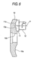
- Fig. 6 is a sectional view of the disk 10 in a state where a super finishing stone (grindstone) 11 is abutted against the raceway surface 10a.
- the super finishing stone 11 is supported by a support part 12, and oscillates around a center P of curvature of the raceway surface 10a within a predetermined angle range. With this super finishing stone, the super finishing work is performed on the raceway surface 10a.
- Figs. 5A and 5B seven sections from section A-A to section G-G in the drawing as desired sections which intersect a radial direction of the disk 10 are imagined, for example.
- the raceway surface 10a which is a three-dimensional curved surface has a flat shape at an intermediate section D-D, and comes into a convex shape which is gradually swelled toward a center of the section in order from the section E-E, the section F-F, to the section G-G inwardly in the radial direction.
- the raceway surface 10a comes into a concave shape which is gradually recessed toward a center of the section in order from the section C-C, the section B-B, to the section A-A.
- Figs. 7A and 7B are respectively a front view and a side view of the super finishing stone 11 which has been conventionally used.
- the super finishing stone 11 has a constant width W, and a so-called hog-backed shape as seen in a side view.
- Seven sections from section A-A to section G-G corresponding to the sections of the raceway surface 10a are imagined on an abrasive (grinding) surface 11a after the work (disk) has been oriented.
- the abrasive surface 11a has a flat shape at an intermediate section D-D, and comes into a concave shape which is gradually recessed toward a center of the section in order from the section E-E, the section F-F, to the section G-G inwardly in the radial direction.
- the abrasive surface 11a comes into a convex shape which is gradually swelled toward a center of the section in order from the section C-C, the section B-B, to the section A-A.
- surface profiles of the raceway surface 10a and the abrasive surface 11a match with each other in a convex-concave relation.
- the aforesaid super finishing stone 11 can oscillate as described above.
- the super finishing stone 11 has oscillated outward in the radial direction by an angle d ⁇ from a position where the surface profiles of the raceway surface 10a and the abrasive surface 11a match with each other (for example, a center of an angle of oscillation), as shown in Fig. 6, the abrasive surface to be abutted against the raceway surface 10a is displaced.
- the section E-E of the abrasive surface is abutted against the section D-D of the raceway surface.
- FIG. 8 is a view showing a state of contact between the raceway surface 10a and the abrasive surface 11a in case where they are displaced from each other.
- solid lines represent the profile of the abrasive surface 11a
- dotted lines represent the profile of the raceway surface 10a. Curvature becomes larger in order from a convex 1, a convex 2, to a convex 3, and in order from a concave 1, a concave 2, to a concave 3.
- a super finishing stone for performing a super finishing work on a raceway surface, for receiving a thrust load, of an object to be worked, the super finishing stone comprising:
- a super finishing method of super finishing a raceway surface of an object to be worked in which the raceway surface has a flat shape at an intermediate section thereof in the radial direction when seeing at a plurality of sections perpendicular to a radial direction of the object, comes into a convex shape which is gradually swelled toward a center of the section as approaching inwardly in the radial direction, and comes into a concave shape which is gradually recessed toward a center of the section as approaching outwardly in the radially direction, the method comprising the steps of:
- FIG. 1A is a front view showing a super finishing stone (grindstone) 1
- Fig. 1B is a side view thereof.
- Fig. 2 is a perspective view of the super finishing stone 1.
- a radial direction of an abrasive (grinding) surface 1a which corresponds to the radial direction of the disk 10 is determined as a direction Y, and directions X, Y, Z which are perpendicular to one another are determined as shown in the drawings.
- a back surface 1b of the grinder 1 at an opposite side to the abrasive surface 1a, an inward end surface 1c, and an outward end surface 1d in the radial direction are flat or substantially flat.
- the abrasive surface 1a as seen in a side view has an arc-shape which is convex in the direction Z, and has a largest thickness at a center in the direction Y.
- a width of the abrasive surface 1a in the direction X gradually becomes smaller in a direction perpendicular to the radial direction from upside to downside in the direction Y, that is, from outside to inside in the radial direction (in other words, the width of the abrasive surface 1a becomes larger in the direction perpendicular to the radial direction, from the inside to the outside in the radial direction).
- the opposite side surfaces le, If are nearly flat surfaces having a moderate curve, and composed of a plurality of curved surfaces which are slightly different from one another in a radius of curvature, for example.
- abrasive surface 1a has a flat shape at an intermediate section D-D, and comes into a concave shape which is gradually recessed toward a center of the section in order from the section E-E, the section F-F, to the section G-G inwardly in the radial direction.
- the abrasive surface 1a comes into a convex shape which is gradually swelled toward a center of the section in order from the section C-C, the section B-B, to the section A-A.
- surface profiles of the raceway surface 10a and the abrasive surface 1a match with each other in a convex-concave relation.
- Fig. 4 is a sectional view of the disk 10 in a state where the super finishing stone 1 is abutted against the raceway surface 10a.
- the super finishing stone 1 is supported by the support part 2 and oscillates within a predetermined angle range around a center of curvature P of the raceway surface 10a.
- Super finishing work is performed on the raceway surface 10a by means of the super finishing stone 1 as shown in Fig. 4.
- the super finishing stone 1 has oscillated by an angle d ⁇ outward in the radial direction from a position where the surface profiles (curved surfaces) of the raceway surface 10a and the abrasive surface 1a match with each other (a center of the angle of oscillation, for example), as shown in Fig. 4, the abrasive surface to be abutted against the raceway surface 10a is displaced.
- the section E-E of the abrasive surface may be abutted against the section D-D of the raceway surface.
- Fig. 3 is a view showing the raceway surface 10a and the abrasive surface 1a in case where they are displaced from each other.
- the raceway surface 10a and the abrasive surface 1a are shown in a state where they are in contact with each other at a plurality of (seven) positions of the sections (the sections in parallel with the X-Z plane) which are perpendicular to the radial direction (the direction Y).
- solid lines represent the profile of the abrasive surface 1a
- dotted lines represent the profile of the raceway surface 10a.
- the curvature becomes larger in order from convex 1, convex 2, to convex 3, and in order from concave 1, concave 2, to concave 3.
- the abrasive surface 1a as seen at the respective sections is abutted against the raceway surface 10a at opposite side edges thereof.
- the curvatures of the abrasive surface 1a and the raceway surface 10a vary depending on the sections in the radial direction at which they are seen.
- the width W of the abrasive surface 1a is varied so that an intersection angle d ⁇ between the abrasive surface 1a and the raceway surface 10a at the opposite side edges of the abrasive surface 1a may be the same at all the sections.
- the width W of the abrasive surface 1a is gradually mage smaller, inwardly in the radial direction.
- the state of contact between the abrasive surface 1a and the raceway surface 10a at the opposite side edges of the abrasive surface 1a or in their vicinity is made constant, and the edge loads can be made constant. Accordingly, working conditions at all the positions are made constant, and hence, occurrence of unevenness in finishing can be restrained.
- the object to be worked is the power transmission disk of the toroidal continuously variable transmission.
- the super finishing stone as described above can be used for super finishing raceway surfaces in various other objects to be worked (for example, a thrust ball bearing) each having the raceway surface for receiving a thrust load.
Landscapes
- Engineering & Computer Science (AREA)
- Mechanical Engineering (AREA)
- General Engineering & Computer Science (AREA)
- Polishing Bodies And Polishing Tools (AREA)
- Finish Polishing, Edge Sharpening, And Grinding By Specific Grinding Devices (AREA)
- Grinding And Polishing Of Tertiary Curved Surfaces And Surfaces With Complex Shapes (AREA)
- Friction Gearing (AREA)
Abstract
Description
- The present invention relates to a super finishing stone which performs super finishing work on a raceway surface of an object to be worked such as a power transmission disk of a toroidal continuously variable transmission and rings of a thrust ball bearing, which has a raceway surface for receiving a thrust load, and a super finishing method.
- In the disk of the toroidal continuously variable transmission, for example, the raceway surface having an arc-shape in cross section is continuously formed in a circumferential direction (Reference shouldbemade to
Japanese Patent Publication No. JP-A-2002-295618 disk 10 of this type and Fig. 5B is a front view thereof. In the drawings, thedisk 10 is formed with afitting hole 10b to be fitted to a shaft (not shown) at a center thereof, and araceway surface 10a on one surface thereof. Theraceway surface 10a which has been formed in a predetermined shape in advance, as shown in the drawings, is further super finished by a super finishing stone, by rotating thedisk 10 around its axis. - Fig. 6 is a sectional view of the
disk 10 in a state where a super finishing stone (grindstone) 11 is abutted against theraceway surface 10a. The super finishingstone 11 is supported by asupport part 12, and oscillates around a center P of curvature of theraceway surface 10a within a predetermined angle range. With this super finishing stone, the super finishing work is performed on theraceway surface 10a. - In Figs. 5A and 5B, seven sections from section A-A to section G-G in the drawing as desired sections which intersect a radial direction of the
disk 10 are imagined, for example. Theraceway surface 10a which is a three-dimensional curved surface has a flat shape at an intermediate section D-D, and comes into a convex shape which is gradually swelled toward a center of the section in order from the section E-E, the section F-F, to the section G-G inwardly in the radial direction. On the other hand, theraceway surface 10a comes into a concave shape which is gradually recessed toward a center of the section in order from the section C-C, the section B-B, to the section A-A. - Figs. 7A and 7B are respectively a front view and a side view of the super finishing
stone 11 which has been conventionally used. The super finishingstone 11 has a constant width W, and a so-called hog-backed shape as seen in a side view. Seven sections from section A-A to section G-G corresponding to the sections of theraceway surface 10a are imagined on an abrasive (grinding)surface 11a after the work (disk) has been oriented. Theabrasive surface 11a has a flat shape at an intermediate section D-D, and comes into a concave shape which is gradually recessed toward a center of the section in order from the section E-E, the section F-F, to the section G-G inwardly in the radial direction. On the other hand, theabrasive surface 11a comes into a convex shape which is gradually swelled toward a center of the section in order from the section C-C, the section B-B, to the section A-A. In short, surface profiles of theraceway surface 10a and theabrasive surface 11a match with each other in a convex-concave relation. - The aforesaid super finishing
stone 11 can oscillate as described above. In case where the super finishingstone 11 has oscillated outward in the radial direction by an angle d ω from a position where the surface profiles of theraceway surface 10a and theabrasive surface 11a match with each other (for example, a center of an angle of oscillation), as shown in Fig. 6, the abrasive surface to be abutted against theraceway surface 10a is displaced. For example, in the above described case, the section E-E of the abrasive surface is abutted against the section D-D of the raceway surface. Fig. 8 is a view showing a state of contact between theraceway surface 10a and theabrasive surface 11a in case where they are displaced from each other. In Fig. 8, solid lines represent the profile of theabrasive surface 11a, and dotted lines represent the profile of theraceway surface 10a. Curvature becomes larger in order from aconvex 1, aconvex 2, to aconvex 3, and in order from a concave 1, a concave 2, to a concave 3. - In this case, an entirety of the
abrasive surface 11a as seen at one section will not come into contact with theraceway surface 10a, but only right and left edges of theabrasive surface 11a in a sectional shape come into contact with theraceway surface 10a. In fact, however, regions close to the edges also come into contact, as the curvature becomes smaller. However, as shown in Fig. B, the contacted regions are concentrated to opposite side ends as going inward in the radial direction, which leads to high edge load condition. As the results, there is a problem that working conditions become inconstant depending on positions, and unevenness in super finishing may occur. - In view of such problems in the related art, it is an object of the invention to provide a super finishing stone with which occurrence of unevenness in finishing can be restrained, even though the super finishing stone oscillates, and a super finishing stone.
- According to the invention, there is provided a super finishing stone for performing a super finishing work on a raceway surface, for receiving a thrust load, of an object to be worked, the super finishing stone comprising:
- an abrasive surface having a shape in which a width of the abrasive surface becomes gradually narrower from outside to inside in a radial direction of the object, so that, when the raceway surface and the abrasive surface in contact with the raceway surface are seen at a plurality of sections perpendicular to the radial direction of the object, intersection angles between the abrasive surface and the raceway surface in contact with the abrasive surface at opposite side edges of the abrasive surface are made constant.
- In the super finishing stone having the above described structure, although the opposite side edges of the abrasive surface as seen at the respective sections are abutted against the raceway surface along with the oscillation outward in the radial direction, the intersection angles between the abrasive surface and the raceway surface are made constant at the respective sections. Accordingly, the state of contact is made constant and hence, the edge load can be made constant.
According to the invention, there is provided a super finishing method of super finishing a raceway surface of an object to be worked, in which the raceway surface has a flat shape at an intermediate section thereof in the radial direction when seeing at a plurality of sections perpendicular to a radial direction of the object, comes into a convex shape which is gradually swelled toward a center of the section as approaching inwardly in the radial direction, and comes into a concave shape which is gradually recessed toward a center of the section as approaching outwardly in the radially direction, the method comprising the steps of: - disposing a super finishing stone according to
claim 3 so that surface profiles of the raceway surface and the abrasive surface match with each other in a convex-concave relation, and - oscillating the super finishing stone in the radial direction within a predetermined angle range around a center of curvature of the raceway surface.
- According to the super finishing stone of the invention, unevenness in finishing can be restrained, even in case where the opposite side edges of the abrasive surface are abutted against the raceway surface along with the oscillation.
-
- Fig. 1A is a front view showing a super finishing stone in an embodiment according to the invention and Fig. 1B is a side view thereof.
- Fig. 2 is a perspective view of the super finishing stone as shown in Fig. 1.
- Fig. 3 is a view showing a state of contact between a raceway surface and an abrasive surface in case where they are displaced from each other, as seen at a plurality of positions of sections perpendicular to the radial direction.
- Fig. 4 is a sectional view of a disk in a state where the super finishing stone is abutted against the raceway surface of the disk.
- Fig. 5A is a sectional view showing a power transmission disk of a toroidal continuously variable transmission, and Fig. 5B is a front view thereof.
- Fig. 6 is a sectional view of the disk in a state where a conventional super finishing stone is abutted against a raceway surface of the disk.
- Fig. 7A is a front view showing the super finishing stone which has been conventionally used, and Fig. 7B is a side view thereof.
- Fig. 8 is a view of the conventional super finishing stone showing a state of contact between the raceway surface and the abrasive surface, in case where they are displaced from each other.
- Now, a super finishing stone in an embodiment according to the invention will be described, referring to the drawings. An object to be worked is the
power transmission disk 10 of full toroidal continuously variable transmission which is one kind of the aforesaid toroidal continuously variable transmission, as shown in Fig. 5.
Fig. 1A is a front view showing a super finishing stone (grindstone) 1, and Fig. 1B is a side view thereof. Fig. 2 is a perspective view of thesuper finishing stone 1. In the drawings, a radial direction of an abrasive (grinding)surface 1a which corresponds to the radial direction of thedisk 10 is determined as a direction Y, and directions X, Y, Z which are perpendicular to one another are determined as shown in the drawings. Aback surface 1b of thegrinder 1 at an opposite side to theabrasive surface 1a, aninward end surface 1c, and anoutward end surface 1d in the radial direction are flat or substantially flat. - On the other hand, the
abrasive surface 1a as seen in a side view has an arc-shape which is convex in the direction Z, and has a largest thickness at a center in the direction Y. A width of theabrasive surface 1a in the direction X gradually becomes smaller in a direction perpendicular to the radial direction from upside to downside in the direction Y, that is, from outside to inside in the radial direction (in other words, the width of theabrasive surface 1a becomes larger in the direction perpendicular to the radial direction, from the inside to the outside in the radial direction). Moreover, the opposite side surfaces le, If are nearly flat surfaces having a moderate curve, and composed of a plurality of curved surfaces which are slightly different from one another in a radius of curvature, for example. - In Fig. 2, seven sections from section A-A to section G-G (sections in parallel with an X-Z plane) corresponding to the sections of the
raceway surface 10a (Figs. 5A and 5B) are imagined on anabrasive surface 1a. Theabrasive surface 1a has a flat shape at an intermediate section D-D, and comes into a concave shape which is gradually recessed toward a center of the section in order from the section E-E, the section F-F, to the section G-G inwardly in the radial direction. On the other hand, theabrasive surface 1a comes into a convex shape which is gradually swelled toward a center of the section in order from the section C-C, the section B-B, to the section A-A. In this manner, surface profiles of theraceway surface 10a and theabrasive surface 1a match with each other in a convex-concave relation. - Fig. 4 is a sectional view of the
disk 10 in a state where the super finishingstone 1 is abutted against theraceway surface 10a. Thesuper finishing stone 1 is supported by thesupport part 2 and oscillates within a predetermined angle range around a center of curvature P of theraceway surface 10a. Super finishing work is performed on theraceway surface 10a by means of thesuper finishing stone 1 as shown in Fig. 4. - In case where the super finishing
stone 1 has oscillated by an angle dω outward in the radial direction from a position where the surface profiles (curved surfaces) of theraceway surface 10a and theabrasive surface 1a match with each other (a center of the angle of oscillation, for example), as shown in Fig. 4, the abrasive surface to be abutted against theraceway surface 10a is displaced. For example, in the above described embodiment, the section E-E of the abrasive surface may be abutted against the section D-D of the raceway surface. Fig. 3 is a view showing theraceway surface 10a and theabrasive surface 1a in case where they are displaced from each other. Theraceway surface 10a and theabrasive surface 1a are shown in a state where they are in contact with each other at a plurality of (seven) positions of the sections (the sections in parallel with the X-Z plane) which are perpendicular to the radial direction (the direction Y). In Fig. 3, solid lines represent the profile of theabrasive surface 1a, and dotted lines represent the profile of theraceway surface 10a. The curvature becomes larger in order from convex 1, convex 2, to convex 3, and in order from concave 1, concave 2, to concave 3. - In Fig. 3, the
abrasive surface 1a as seen at the respective sections is abutted against theraceway surface 10a at opposite side edges thereof. Moreover, the curvatures of theabrasive surface 1a and theraceway surface 10a vary depending on the sections in the radial direction at which they are seen. Now, the width W of theabrasive surface 1a is varied so that an intersection angle dθ between theabrasive surface 1a and theraceway surface 10a at the opposite side edges of theabrasive surface 1a may be the same at all the sections. In short, the width W of theabrasive surface 1a is gradually mage smaller, inwardly in the radial direction. In this manner, the state of contact between theabrasive surface 1a and theraceway surface 10a at the opposite side edges of theabrasive surface 1a or in their vicinity is made constant, and the edge loads can be made constant. Accordingly, working conditions at all the positions are made constant, and hence, occurrence of unevenness in finishing can be restrained. - It is ideal that the variation in the width of the
abrasive surface 1a, as described above, continues so that the aforesaid intersection angle dθ may be constant at a desired section. However, in case where the grinder has such a profile that the width of the abrasive surface becomes narrower from the outside to the inside in the radial direction, and has a limited number of sections, it is possible to obtain a certain effect that occurrence of unevenness in finishing is restrained (or reduced) by varying the width so that a difference between the angles dθ may become smaller and the intersection angles dθ may be made constant at the respective sections. - In the above described embodiment, the object to be worked is the power transmission disk of the toroidal continuously variable transmission. However, the super finishing stone as described above can be used for super finishing raceway surfaces in various other objects to be worked (for example, a thrust ball bearing) each having the raceway surface for receiving a thrust load.
Claims (4)
- A super finishing stone for performing super finishing work on a raceway surface, for receiving a thrust load, of an object to be worked, the super finishing stone comprising:an abrasive surface having a shape in which a width of the abrasive surface becomes gradually narrower from outside to inside in a radial direction of the object, so that, when the raceway surface and the abrasive surface in contact with the raceway surface are seen at a plurality of sections perpendicular to the radial direction of the object, intersection angles between the abrasive surface and the raceway surface in contact with the abrasive surface at opposite side edges of the abrasive surface are made constant.
- The super finishing stone according to claim 1, wherein
the raceway surface has a flat shape at an intermediate section thereof in the radial direction when seeing at the plurality of sections,
the raceway surface comes into a convex shape which is gradually swelled toward a center of the section as approaching inwardly in the radial direction, and
the raceway surface comes into a concave shape which is gradually recessed toward a center of the section as approaching outwardly in the radially direction. - The super finishing stone according to claim 2, wherein
the abrasive surface has a flat shape at an intermediate section thereof in the radial direction when seeing at the plurality of sections,
the abrasive surface comes into a concave shape which is gradually recessed toward a center of the section as approaching inwardly in the radial direction, and
the abrasive surface comes into a convex shape which is gradually swelled toward a center of the section as approaching outwardly in the radially direction. - A super finishing method of super finishing a raceway surface of an object to be worked, in which the raceway surface has a flat shape at an intermediate section thereof in the radial direction when seeing at a plurality of sections perpendicular to a radial direction of the object, comes into a convex shape which is gradually swelled toward a center of the section as approaching inwardly in the radial direction, and comes into a concave shape which is gradually recessed toward a center of the section as approaching outwardly in the radially direction, the method comprising the steps of:disposing a super finishing stone according to claim 3 so that surface profiles of the raceway surface and the abrasive surface match with each other in a convex-concave relation, andoscillating the super finishing stone in the radial direction within a predetermined angle range around a center of curvature of the raceway surface.
Applications Claiming Priority (1)
| Application Number | Priority Date | Filing Date | Title |
|---|---|---|---|
| JP2006249095A JP5045040B2 (en) | 2006-09-14 | 2006-09-14 | Super finishing whetstone |
Publications (2)
| Publication Number | Publication Date |
|---|---|
| EP1900478A1 true EP1900478A1 (en) | 2008-03-19 |
| EP1900478B1 EP1900478B1 (en) | 2009-11-11 |
Family
ID=38662699
Family Applications (1)
| Application Number | Title | Priority Date | Filing Date |
|---|---|---|---|
| EP07018007A Ceased EP1900478B1 (en) | 2006-09-14 | 2007-09-13 | Super finishing stone and super finishing method |
Country Status (4)
| Country | Link |
|---|---|
| US (1) | US8007551B2 (en) |
| EP (1) | EP1900478B1 (en) |
| JP (1) | JP5045040B2 (en) |
| DE (1) | DE602007003159D1 (en) |
Cited By (2)
| Publication number | Priority date | Publication date | Assignee | Title |
|---|---|---|---|---|
| JP2012035342A (en) * | 2010-08-04 | 2012-02-23 | Jtekt Corp | Method and device for polishing disk of toroidal type continuously variable transmission |
| CN106217231A (en) * | 2016-07-29 | 2016-12-14 | 河南科技大学 | A kind of deep groove ball bearing ring raceways superfinishing oilstone and super precision method thereof |
Families Citing this family (4)
| Publication number | Priority date | Publication date | Assignee | Title |
|---|---|---|---|---|
| US8665160B2 (en) | 2011-01-31 | 2014-03-04 | Apple Inc. | Antenna, shielding and grounding |
| US8587939B2 (en) | 2011-01-31 | 2013-11-19 | Apple Inc. | Handheld portable device |
| US8911280B2 (en) * | 2011-01-31 | 2014-12-16 | Apple Inc. | Apparatus for shaping exterior surface of a metal alloy casing |
| WO2017175255A1 (en) * | 2016-04-06 | 2017-10-12 | 川崎重工業株式会社 | Toroidal continuously variable transmission |
Citations (3)
| Publication number | Priority date | Publication date | Assignee | Title |
|---|---|---|---|---|
| US6402600B1 (en) * | 2000-10-30 | 2002-06-11 | Othmar C. Besch | Bowling ball surface abrading and polishing tool assembly |
| JP2002192450A (en) | 2000-12-25 | 2002-07-10 | Nissan Motor Co Ltd | Processing method and processing apparatus for rolling element for toroidal type continuously variable transmission |
| US20030060152A1 (en) * | 2001-08-31 | 2003-03-27 | Lee Chang Hyun | Abrasive wheel |
Family Cites Families (4)
| Publication number | Priority date | Publication date | Assignee | Title |
|---|---|---|---|---|
| JPH11277447A (en) * | 1998-03-27 | 1999-10-12 | Nippon Seiko Kk | Super finishing whetstone |
| JP2002295618A (en) | 2001-04-03 | 2002-10-09 | Koyo Seiko Co Ltd | Toroidal continuously variable speed transmission |
| JP3861659B2 (en) * | 2001-11-08 | 2006-12-20 | 日本精工株式会社 | Super finishing method of gothic arc groove |
| JP4110396B2 (en) * | 2003-02-28 | 2008-07-02 | 日本精工株式会社 | Super finishing method and super finishing device for bearing raceway surface |
-
2006
- 2006-09-14 JP JP2006249095A patent/JP5045040B2/en not_active Expired - Fee Related
-
2007
- 2007-09-13 EP EP07018007A patent/EP1900478B1/en not_active Ceased
- 2007-09-13 US US11/898,580 patent/US8007551B2/en not_active Expired - Fee Related
- 2007-09-13 DE DE602007003159T patent/DE602007003159D1/en active Active
Patent Citations (3)
| Publication number | Priority date | Publication date | Assignee | Title |
|---|---|---|---|---|
| US6402600B1 (en) * | 2000-10-30 | 2002-06-11 | Othmar C. Besch | Bowling ball surface abrading and polishing tool assembly |
| JP2002192450A (en) | 2000-12-25 | 2002-07-10 | Nissan Motor Co Ltd | Processing method and processing apparatus for rolling element for toroidal type continuously variable transmission |
| US20030060152A1 (en) * | 2001-08-31 | 2003-03-27 | Lee Chang Hyun | Abrasive wheel |
Cited By (2)
| Publication number | Priority date | Publication date | Assignee | Title |
|---|---|---|---|---|
| JP2012035342A (en) * | 2010-08-04 | 2012-02-23 | Jtekt Corp | Method and device for polishing disk of toroidal type continuously variable transmission |
| CN106217231A (en) * | 2016-07-29 | 2016-12-14 | 河南科技大学 | A kind of deep groove ball bearing ring raceways superfinishing oilstone and super precision method thereof |
Also Published As
| Publication number | Publication date |
|---|---|
| JP5045040B2 (en) | 2012-10-10 |
| JP2008068362A (en) | 2008-03-27 |
| US20080066386A1 (en) | 2008-03-20 |
| DE602007003159D1 (en) | 2009-12-24 |
| US8007551B2 (en) | 2011-08-30 |
| EP1900478B1 (en) | 2009-11-11 |
Similar Documents
| Publication | Publication Date | Title |
|---|---|---|
| US8007551B2 (en) | Super finishing stone and super finishing method | |
| US8632257B2 (en) | Rolling bearing and method for the production thereof | |
| KR101479829B1 (en) | Formed cutter manufacturing method and formed cutter grinding tool | |
| KR20140002630A (en) | insert | |
| JP2016529118A5 (en) | ||
| WO2010001706A1 (en) | Bearing roller, bearing, and bearing roller processing method | |
| CN104321547B (en) | Middle web crankshaft having forged stress relief | |
| WO2016147827A1 (en) | Tripod constant velocity universal joint | |
| WO2018159539A1 (en) | Roller gear cam mechanism | |
| CN110809677A (en) | Method for producing a component of a tilting pad bearing and tilting pad bearing | |
| JP6307156B2 (en) | Ball joint with load optimized ball shell | |
| US6450916B2 (en) | Cam disc of loading cam mechanism in toroidal type continuously variable transmission and manufacturing method therefor | |
| KR20190087771A (en) | Jig for cutting work for plain bearing | |
| WO2017014001A1 (en) | Superfinishing method for roller bearing rolling surface | |
| JP5747723B2 (en) | Trunnion of toroidal type continuously variable transmission and processing method thereof | |
| CN107186550B (en) | A kind of processing method of curved slit | |
| JP6546547B2 (en) | Pulley structure | |
| JP2005061494A (en) | Method for manufacturing variator part of continuously variable transmission and variator part of continuously variable transmission | |
| JP5672733B2 (en) | Power transmission chain pin grinding apparatus and grinding method | |
| JP3534267B2 (en) | Super finishing wheel and super finishing grinding method | |
| JP2014016007A (en) | Tripod type constant velocity joint and manufacturing method thereof | |
| JP2007301700A (en) | Grinding wheel with multilayer structure | |
| JP2021020279A (en) | Gear processing end mill and gear processing method with use thereof | |
| KR102940353B1 (en) | ball end mill | |
| CN107000073B (en) | drilling tool |
Legal Events
| Date | Code | Title | Description |
|---|---|---|---|
| PUAI | Public reference made under article 153(3) epc to a published international application that has entered the european phase |
Free format text: ORIGINAL CODE: 0009012 |
|
| AK | Designated contracting states |
Kind code of ref document: A1 Designated state(s): AT BE BG CH CY CZ DE DK EE ES FI FR GB GR HU IE IS IT LI LT LU LV MC MT NL PL PT RO SE SI SK TR |
|
| AX | Request for extension of the european patent |
Extension state: AL BA HR MK YU |
|
| 17P | Request for examination filed |
Effective date: 20080919 |
|
| AKX | Designation fees paid |
Designated state(s): DE FR |
|
| 17Q | First examination report despatched |
Effective date: 20081031 |
|
| GRAP | Despatch of communication of intention to grant a patent |
Free format text: ORIGINAL CODE: EPIDOSNIGR1 |
|
| GRAS | Grant fee paid |
Free format text: ORIGINAL CODE: EPIDOSNIGR3 |
|
| GRAA | (expected) grant |
Free format text: ORIGINAL CODE: 0009210 |
|
| AK | Designated contracting states |
Kind code of ref document: B1 Designated state(s): DE FR |
|
| REF | Corresponds to: |
Ref document number: 602007003159 Country of ref document: DE Date of ref document: 20091224 Kind code of ref document: P |
|
| PLBE | No opposition filed within time limit |
Free format text: ORIGINAL CODE: 0009261 |
|
| STAA | Information on the status of an ep patent application or granted ep patent |
Free format text: STATUS: NO OPPOSITION FILED WITHIN TIME LIMIT |
|
| 26N | No opposition filed |
Effective date: 20100812 |
|
| REG | Reference to a national code |
Ref country code: FR Ref legal event code: PLFP Year of fee payment: 10 |
|
| REG | Reference to a national code |
Ref country code: FR Ref legal event code: PLFP Year of fee payment: 11 |
|
| REG | Reference to a national code |
Ref country code: FR Ref legal event code: PLFP Year of fee payment: 12 |
|
| PGFP | Annual fee paid to national office [announced via postgrant information from national office to epo] |
Ref country code: FR Payment date: 20200812 Year of fee payment: 14 Ref country code: DE Payment date: 20200901 Year of fee payment: 14 |
|
| REG | Reference to a national code |
Ref country code: DE Ref legal event code: R119 Ref document number: 602007003159 Country of ref document: DE |
|
| PG25 | Lapsed in a contracting state [announced via postgrant information from national office to epo] |
Ref country code: FR Free format text: LAPSE BECAUSE OF NON-PAYMENT OF DUE FEES Effective date: 20210930 Ref country code: DE Free format text: LAPSE BECAUSE OF NON-PAYMENT OF DUE FEES Effective date: 20220401 |