EP1900350A2 - Backpack relocator - Google Patents
Backpack relocator Download PDFInfo
- Publication number
- EP1900350A2 EP1900350A2 EP07116616A EP07116616A EP1900350A2 EP 1900350 A2 EP1900350 A2 EP 1900350A2 EP 07116616 A EP07116616 A EP 07116616A EP 07116616 A EP07116616 A EP 07116616A EP 1900350 A2 EP1900350 A2 EP 1900350A2
- Authority
- EP
- European Patent Office
- Prior art keywords
- linkage
- wheelchair
- slider
- rail
- storage
- Prior art date
- Legal status (The legal status is an assumption and is not a legal conclusion. Google has not performed a legal analysis and makes no representation as to the accuracy of the status listed.)
- Granted
Links
Images



Classifications
-
- A—HUMAN NECESSITIES
- A61—MEDICAL OR VETERINARY SCIENCE; HYGIENE
- A61G—TRANSPORT, PERSONAL CONVEYANCES, OR ACCOMMODATION SPECIALLY ADAPTED FOR PATIENTS OR DISABLED PERSONS; OPERATING TABLES OR CHAIRS; CHAIRS FOR DENTISTRY; FUNERAL DEVICES
- A61G5/00—Chairs or personal conveyances specially adapted for patients or disabled persons, e.g. wheelchairs
- A61G5/10—Parts, details or accessories
-
- A—HUMAN NECESSITIES
- A61—MEDICAL OR VETERINARY SCIENCE; HYGIENE
- A61G—TRANSPORT, PERSONAL CONVEYANCES, OR ACCOMMODATION SPECIALLY ADAPTED FOR PATIENTS OR DISABLED PERSONS; OPERATING TABLES OR CHAIRS; CHAIRS FOR DENTISTRY; FUNERAL DEVICES
- A61G5/00—Chairs or personal conveyances specially adapted for patients or disabled persons, e.g. wheelchairs
- A61G5/10—Parts, details or accessories
- A61G5/1054—Large wheels, e.g. higher than the seat portion
-
- A—HUMAN NECESSITIES
- A61—MEDICAL OR VETERINARY SCIENCE; HYGIENE
- A61G—TRANSPORT, PERSONAL CONVEYANCES, OR ACCOMMODATION SPECIALLY ADAPTED FOR PATIENTS OR DISABLED PERSONS; OPERATING TABLES OR CHAIRS; CHAIRS FOR DENTISTRY; FUNERAL DEVICES
- A61G5/00—Chairs or personal conveyances specially adapted for patients or disabled persons, e.g. wheelchairs
- A61G5/10—Parts, details or accessories
- A61G5/1094—Tables, working plates or trays
Definitions
- This invention relates to a device facilitating storage on a mobility device. More specifically, the invention relocates a bag or storage unit from a storage position behind the mobility device, like a wheelchair, to an accessible position alongside the mobility device.
- Wheelchairs and other mobility devices provide disabled persons a way to move around, relatively unassisted by others.
- wheelchairs do not provide storage for personal belongings.
- Individuals using wheelchairs as part of their every-day lives often have unique needs when carrying personal belongings and other items.
- the typical student will often carry his or her books in a backpack when going to and from school.
- These packs are generally a convenient method for transporting books, but a wheelchair user may find certain aspects of a backpack inconvenient or undesirable for their needs.
- the backpack must be placed on the chair in a position that would be secure, such as the rear of the chair.
- the secure position may make it extremely difficult to retrieve books and other personal effects from the securely attached pack. Consequently, what is needed is a device that would allow a disabled individual to secure a storage device to a chair for transport while allowing the individual convenient access to the contents of the pack when desired.
- Kekler U.S. Pat. No. 4,919,443
- Letechipia U.S. Pat. No. 5,180,181
- Kekler U.S. Pat. No. 4,919,443
- Letechipia U.S. Pat. No. 5,180,181
- Roberts, et al. U.S. Pat. No. 5,299,824
- a tray that horizontally rotates from the back of the wheelchair to the front, on its axis.
- a focus on backpack storage and retrieval solutions has prompted devices designed to hold a backpack, stored behind the wheelchair and deployed horizontally beside the wheelchair's armrest, as evidenced by Perez, et al.
- the current invention provides a way to store belongings behind the wheelchair, and to access the storage without requiring a large space to deploy the storage and retrieval product.
- the bag slides from behind the wheelchair to the side of the chair, allowing the user access to the contents of the storage device.
- Current designs pivot, taking up the full length of the retrieval product, as the product swings around on its axis.
- a mobility device is defined as a device which allows a disabled individual to move around. Illustrative examples include wheelchairs and scooters.
- the invention is a backpack or bag relocation device for use on a wheelchair.
- the relocation device consists of a rail, running along one side of the wheelchair from the front of the wheelchair armrest back behind the seatback of the wheelchair.
- a slider is linked to the rail, so that the slider moves from a stored position behind the user to a deployed position beside the wheelchair armrest.
- a first linkage is attached to the slider, via a horizontal pivot on one end of the linkage.
- a second linkage is connected at one end to the end of the first linkage opposite to the slider pivot.
- the linkages are connected using another horizontally pivoting joint.
- a motor is connected to the other end of the second linkage, driving the device from a stored position to a deployed position. The motor rotates the second linkage horizontally along a vertical axis. The rotation of the second linkage pushes on the first linkage, causing the slider to move along the rail from behind the wheelchair user to a position alongside the armrest.
- the rail runs alongside the wheelchair, and is above the first and second linkages.
- the slider In its stored position, the slider is behind the wheelchair seatback, and the first linkage is substantially perpendicular to the rail.
- the first linkage When the slider is deployed alongside the wheelchair armrest, the first linkage is aligned with the rail and substantially parallel thereto.
- a receptacle is attached to the first linkage of the device, and designed to receive an article (such as a backpack).
- the article When the device is in its stored position, the article is positioned behind the wheelchair seatback. During deployment, the bag slides and rotates forward to a position alongside the wheelchair.
- a U-shaped mounting bracket has a tube on one end of the bracket and a lateral surface on the opposing end. The lateral surface links the device to the bracket. On the opposing side of the bracket, the tube fits onto the wheelchair, linking the device to the wheelchair.
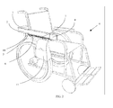
- FIG. 1 is a rear perspective view of the relocating device, shown mounted to a wheelchair.
- the device is in its stored position with a backpack mounted to the device.
- FIG. 2 is a front-quarter perspective view of the relocating device mounted to a wheelchair. As shown, the device is fully deployed with a backpack mounted to the device
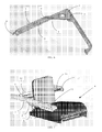
- FIG. 3 is a rear prospective view of the bottom of the relocating device (depicted in its stored position).
- FIG. 4 is a bottom plan view of the relocating device (depicted in its stored position).
- FIG. 5 is a bottom plan view of the relocating device (depicted in its fully deployed position).
- FIG. 6 is front perspective, top-down view of the relocating device (depicted in its fully deployed position).
- FIG. 7 is a front quarter perspective view of the preferred embodiment, where the device is mounted to a wheelchair using a U-shaped bracket.
- the present invention includes a device for retrieving a storage unit from a mobility device, like a wheelchair, as shown in Figs. 1 and 2.
- the device attaches to the mobility device using means known in the art.
- the invention has wide lateral surface 1, located in the back of mobility device 4, just inboard of the side of the mobility device's seatback, seen in Fig. 3.
- the lateral surface is integrated into the U-shaped device, opposite tube mount 13.
- Circular pivot point 5 attaches to the bottom of the lateral surface, seen in Fig. 4.
- Rail guide 2 attaches to lateral surface 1, on the outside edge of the lateral surface. Rail guide 2 extends from the back of mobility device 4, just beyond the lagging edge of lateral surface 1, along the side of mobility device 4, beside the leading edge of an armrest on the mobility device.
- First linkage 7 is attached to circular pivot point 5, normally hidden beneath drive motor 10, on lateral surface 1, so that the arm rotates freely in a horizontal fashion.
- the other end of the first linkage has a circular hole and pin pivot point 6.
- the pin runs through the pivot point on first linkage 7 through second linkage 3, and connects the second linkage to the first.
- the opposing end of the second linkage has a hole and pin pivot 8.
- a pin attaches the end of the second linkage to slider mechanism 9.
- the slider mechanism has a hole in one end, where a pin runs through the slider, attaching the second linkage 3 to the bottom section of the slider mechanism 9, at pivot point 8.
- a surface adjacent to the bottom of slider mechanism 9 is attached to rail guide 2 using a joint that securely attaches the slider to the rail guides, but allows the slider to freely slide along the rail.
- second linkage 3 rotates counterclockwise from a stored position beneath the U-shaped bracket to an extended position below rail guide 2, depicted in Fig. 5 and 6. In its stored position, second linkage 3 is aligned below and perpendicular to the lagging edge of U-shaped bracket 12. Second linkage 3 is attached to first linkage 7 and slider mechanism 9, and substantially perpendicular to the rail guide, as shown in Fig. 6.
- Motor 10 is attached to pivot point 5 beneath the first linkage, on the pivot point attaching second linkage 3 to lateral surface 1.
- the motor's output drive is attached to pivot point 5, driving first linkage 7 counterclockwise from its stored position, to its extended position.
- Second linkage 3 rotates out to its extended position, second linkage 3 pushes first linkage 7 forward.
- First linkage 7 rotates about the second linkage during deployment.
- First linkage 7, pushes forward on slider mechanism 9, which causes slider mechanism 9 to travel forward along rail guides 2.
- slider mechanism 9 As slider mechanism 9 travels forward, first linkage 7 also rotates along the pivot point between first linkage 7 and slider mechanism 9, so that during extension the first linkage rotates about two axis, at pivots 6 and 8, to a position along rail guide 2.
- first linkage 7 is brought perpendicular to, and below, rail guide 2, as shown in Figs. 5 and 6.
- a mounting point attaches to the second linkage, such that the mount is pointing away from the mobility device- user.
- the mounting point is a mount known in the art, preferably a hook.
- the mount is attached to first linkage 7, so that the mount is closer to the slider mechanism than the second linkage, allowing the mobility device- user to mount a storage device, like bag 11 to first linkage 7.
- first linkage 7 travels from its stored position to its extended position, it carries bag 11 from a stored position behind the mobility device to an accessible position beside the mobility device, seen in Figs. 1 and 2.
- This process slides the bag along an oblong path from the back of the mobility device to the side. The process is accomplished without rotating the entire mechanism around a central axis. As such, the movement of the bag from the back of the wheelchair to the side requires considerably less space than the traditional bag relocators.
- the device mounts to the mobility device using U-shaped bracket 12, depicted in Fig. 7.
- Tube 13 is attached to the side of U-shaped bracket 12 opposite lateral surface 1. This enables the U-shaped bracket to mount to horizontal pole 14 on the back of the mobility device.
Landscapes
- Health & Medical Sciences (AREA)
- Life Sciences & Earth Sciences (AREA)
- Animal Behavior & Ethology (AREA)
- General Health & Medical Sciences (AREA)
- Public Health (AREA)
- Veterinary Medicine (AREA)
- Purses, Travelling Bags, Baskets, Or Suitcases (AREA)
- Vehicle Step Arrangements And Article Storage (AREA)
Abstract
Description
- CROSS REFERENCES TO RELATED APPLICATIONS
- This application claims priority to currently pending
U.S. Provisional Patent Application 60/826,018 , entitled "Backpack Relocator", filed September 18, 2006, the contents of which are herein incorporated by reference. - FIELD OF INVENTION
- This invention relates to a device facilitating storage on a mobility device. More specifically, the invention relocates a bag or storage unit from a storage position behind the mobility device, like a wheelchair, to an accessible position alongside the mobility device.
- BACKGROUND OF THE INVENTION
- Wheelchairs and other mobility devices provide disabled persons a way to move around, relatively unassisted by others. However, wheelchairs do not provide storage for personal belongings. Individuals using wheelchairs as part of their every-day lives often have unique needs when carrying personal belongings and other items. For example, the typical student will often carry his or her books in a backpack when going to and from school. These packs are generally a convenient method for transporting books, but a wheelchair user may find certain aspects of a backpack inconvenient or undesirable for their needs. For instance, during transport the backpack must be placed on the chair in a position that would be secure, such as the rear of the chair. Unfortunately, the secure position may make it extremely difficult to retrieve books and other personal effects from the securely attached pack. Consequently, what is needed is a device that would allow a disabled individual to secure a storage device to a chair for transport while allowing the individual convenient access to the contents of the pack when desired.
- The need for storage on wheelchairs and other mobility devices has been recognized for years. However, the articles designed to satisfy this need tend to be bulky, take up large amounts of room while deploying from a stored state to an assessable state, or drastically and adversely affect the stability of the wheelchair. Further, some storage devices are not readily accessible by the disabled person. For example,
Shirk (U.S. Pat. No. 4,861,059 ) provides for a vertically pivoting box behind the wheelchair. The apparatus clamps to the wheelchair, with the storage unit pivoting on rods mounted to the base of the storage unit. However, the box does not rotate to a position where the disabled user may freely access the box. - Kekler (
U.S. Pat. No. 4,919,443 ) andLetechipia (U.S. Pat. No. 5,180,181 ) both describe a storage box or bag that rotates horizontally on an axis mounted to one edge of the storage box or bag, and rotates from behind the wheelchair to a position above the armrest. Likewise,Roberts, et al. (U.S. Pat. No. 5,299,824 ) describes a tray that horizontally rotates from the back of the wheelchair to the front, on its axis. More recently, a focus on backpack storage and retrieval solutions has prompted devices designed to hold a backpack, stored behind the wheelchair and deployed horizontally beside the wheelchair's armrest, as evidenced by Perez, et al. (NSF 2001), Chanchavac, et al. (Proc. Of the IEEE), andMatthew (US Pub. No. 2005/0001405 ). However, these new designs still rely on pivoting the storage unit, here a backpack, around a fixed axis. The bag rotates around on a boom from the rear of the wheelchair to the side, allowing the disabled user access. Thus, the new designs still require large areas to deploy, limiting the usefulness of these products. Further, because these designs transfer the backpack through a large arc, to reach the side of the wheelchair, the wheelchair becomes increasingly unstable as the backpack reaches the apex of this arc. - The current invention provides a way to store belongings behind the wheelchair, and to access the storage without requiring a large space to deploy the storage and retrieval product. When the user wishes to access his or her belongings, the bag slides from behind the wheelchair to the side of the chair, allowing the user access to the contents of the storage device. Current designs pivot, taking up the full length of the retrieval product, as the product swings around on its axis.
- Therefore, what is needed is a device that does not rely on a rotating motion to retrieve the storage device, thereby taking up substantially less space during retrieval and reducing the instability inherent during deployment.
- SUMMARY OF INVENTION
- A mobility device is defined as a device which allows a disabled individual to move around. Illustrative examples include wheelchairs and scooters.
- The invention is a backpack or bag relocation device for use on a wheelchair. The relocation device consists of a rail, running along one side of the wheelchair from the front of the wheelchair armrest back behind the seatback of the wheelchair. A slider is linked to the rail, so that the slider moves from a stored position behind the user to a deployed position beside the wheelchair armrest. A first linkage is attached to the slider, via a horizontal pivot on one end of the linkage. A second linkage is connected at one end to the end of the first linkage opposite to the slider pivot. The linkages are connected using another horizontally pivoting joint. A motor is connected to the other end of the second linkage, driving the device from a stored position to a deployed position. The motor rotates the second linkage horizontally along a vertical axis. The rotation of the second linkage pushes on the first linkage, causing the slider to move along the rail from behind the wheelchair user to a position alongside the armrest.
- In a preferred embodiment, the rail runs alongside the wheelchair, and is above the first and second linkages. In its stored position, the slider is behind the wheelchair seatback, and the first linkage is substantially perpendicular to the rail. When the slider is deployed alongside the wheelchair armrest, the first linkage is aligned with the rail and substantially parallel thereto. A receptacle is attached to the first linkage of the device, and designed to receive an article (such as a backpack). When the device is in its stored position, the article is positioned behind the wheelchair seatback. During deployment, the bag slides and rotates forward to a position alongside the wheelchair.
- A U-shaped mounting bracket has a tube on one end of the bracket and a lateral surface on the opposing end. The lateral surface links the device to the bracket. On the opposing side of the bracket, the tube fits onto the wheelchair, linking the device to the wheelchair.
- BRIEF DESCRIPTION OF THE DRAWINGS
- For a fuller understanding of the invention, reference should be made to the following detailed description, taken in connection with the accompanying drawings, in which:
- FIG. 1 is a rear perspective view of the relocating device, shown mounted to a wheelchair. The device is in its stored position with a backpack mounted to the device.
- FIG. 2 is a front-quarter perspective view of the relocating device mounted to a wheelchair. As shown, the device is fully deployed with a backpack mounted to the device
- FIG. 3 is a rear prospective view of the bottom of the relocating device (depicted in its stored position).
- FIG. 4 is a bottom plan view of the relocating device (depicted in its stored position).
- FIG. 5 is a bottom plan view of the relocating device (depicted in its fully deployed position).
- FIG. 6 is front perspective, top-down view of the relocating device (depicted in its fully deployed position).
- FIG. 7 is a front quarter perspective view of the preferred embodiment, where the device is mounted to a wheelchair using a U-shaped bracket.
- DETAILED DESCRIPTION OF THE PREFERRED EMBODIMENT
- The present invention includes a device for retrieving a storage unit from a mobility device, like a wheelchair, as shown in Figs. 1 and 2. The device attaches to the mobility device using means known in the art. The invention has wide
lateral surface 1, located in the back ofmobility device 4, just inboard of the side of the mobility device's seatback, seen in Fig. 3. Preferably, the lateral surface is integrated into the U-shaped device,opposite tube mount 13.Circular pivot point 5 attaches to the bottom of the lateral surface, seen in Fig. 4.Rail guide 2 attaches tolateral surface 1, on the outside edge of the lateral surface.Rail guide 2 extends from the back ofmobility device 4, just beyond the lagging edge oflateral surface 1, along the side ofmobility device 4, beside the leading edge of an armrest on the mobility device. -
First linkage 7 is attached tocircular pivot point 5, normally hidden beneathdrive motor 10, onlateral surface 1, so that the arm rotates freely in a horizontal fashion. The other end of the first linkage has a circular hole andpin pivot point 6. The pin runs through the pivot point onfirst linkage 7 throughsecond linkage 3, and connects the second linkage to the first. The opposing end of the second linkage has a hole andpin pivot 8. A pin attaches the end of the second linkage toslider mechanism 9. The slider mechanism has a hole in one end, where a pin runs through the slider, attaching thesecond linkage 3 to the bottom section of theslider mechanism 9, atpivot point 8. A surface adjacent to the bottom ofslider mechanism 9 is attached to railguide 2 using a joint that securely attaches the slider to the rail guides, but allows the slider to freely slide along the rail. - During deployment,
second linkage 3 rotates counterclockwise from a stored position beneath the U-shaped bracket to an extended position belowrail guide 2, depicted in Fig. 5 and 6. In its stored position,second linkage 3 is aligned below and perpendicular to the lagging edge ofU-shaped bracket 12.Second linkage 3 is attached tofirst linkage 7 andslider mechanism 9, and substantially perpendicular to the rail guide, as shown in Fig. 6. -
Motor 10 is attached to pivotpoint 5 beneath the first linkage, on the pivot point attachingsecond linkage 3 tolateral surface 1. The motor's output drive is attached to pivotpoint 5, drivingfirst linkage 7 counterclockwise from its stored position, to its extended position. Assecond linkage 3 rotates out to its extended position,second linkage 3 pushesfirst linkage 7 forward.First linkage 7 rotates about the second linkage during deployment.First linkage 7, in turn, pushes forward onslider mechanism 9, which causesslider mechanism 9 to travel forward along rail guides 2. Asslider mechanism 9 travels forward,first linkage 7 also rotates along the pivot point betweenfirst linkage 7 andslider mechanism 9, so that during extension the first linkage rotates about two axis, atpivots rail guide 2. As the slider reaches the extended position,first linkage 7 is brought perpendicular to, and below,rail guide 2, as shown in Figs. 5 and 6. - A mounting point attaches to the second linkage, such that the mount is pointing away from the mobility device- user. The mounting point is a mount known in the art, preferably a hook. The mount is attached to
first linkage 7, so that the mount is closer to the slider mechanism than the second linkage, allowing the mobility device- user to mount a storage device, likebag 11 tofirst linkage 7. Asfirst linkage 7 travels from its stored position to its extended position, it carriesbag 11 from a stored position behind the mobility device to an accessible position beside the mobility device, seen in Figs. 1 and 2. This process slides the bag along an oblong path from the back of the mobility device to the side. The process is accomplished without rotating the entire mechanism around a central axis. As such, the movement of the bag from the back of the wheelchair to the side requires considerably less space than the traditional bag relocators. - Preferably, the device mounts to the mobility device using
U-shaped bracket 12, depicted in Fig. 7.Tube 13 is attached to the side ofU-shaped bracket 12 oppositelateral surface 1. This enables the U-shaped bracket to mount tohorizontal pole 14 on the back of the mobility device. - It will be seen that the advantages set forth above, and those made apparent from the foregoing description, are efficiently attained and since certain changes may be made in the above construction without departing from the scope of the invention, it is intended that all matters contained in the foregoing description or shown in the accompanying drawings shall be interpreted as illustrative and not in a limiting sense.
- It is also to be understood that the following claims are intended to cover all of the generic and specific features of the invention herein described, and all statements of the scope of the invention which, as a matter of language, might be said to fall therebetween. Now that the invention has been described,
Claims (8)
- A device for use with a wheelchair, comprising:a rail disposed along one side of the wheelchair;a slider connected to the rail, wherein the slider is adapted to move between a first position and a second position;a first linkage, pivotally connected to the slider at its first end;a second linkage, pivotally connected to the second of the first linkage at its first end; anda motor connected to the second end of the second linkage;wherein the motor causes the second linkage to rotate along a vertical axis; and
wherein the rotation of the second linkage causes the slider to move between the first position and second position via the first linkage. - The device of claim 1 wherein the first linkage is substantially perpendicular to the rail when the slider is in the second position.
- The device of claim 1 wherein the first linkage is substantially parallel to the rail when the slider is in the first position.
- The device of claim 1, further comprising a receptacle adapted to receive an article.
- The device of claim 4 wherein the receptacle is affixed to the first linkage.
- The device of claim 4 wherein the receptacle is positioned behind the wheelchair when the slider is in the second position.
- The device of claim 4 wherein the receptacle is positioned along the side of the wheelchair when the slider is in the first position.
- The device of claim 1 wherein the rail is disposed in superior relation to the first and second linkage.
Applications Claiming Priority (1)
| Application Number | Priority Date | Filing Date | Title |
|---|---|---|---|
| US82601806P | 2006-09-18 | 2006-09-18 |
Publications (3)
| Publication Number | Publication Date |
|---|---|
| EP1900350A2 true EP1900350A2 (en) | 2008-03-19 |
| EP1900350A3 EP1900350A3 (en) | 2008-10-08 |
| EP1900350B1 EP1900350B1 (en) | 2011-11-23 |
Family
ID=38791130
Family Applications (1)
| Application Number | Title | Priority Date | Filing Date |
|---|---|---|---|
| EP07116616A Not-in-force EP1900350B1 (en) | 2006-09-18 | 2007-09-18 | Backpack relocator |
Country Status (4)
| Country | Link |
|---|---|
| US (1) | US7845667B2 (en) |
| EP (1) | EP1900350B1 (en) |
| AT (1) | ATE534363T1 (en) |
| CA (1) | CA2602606A1 (en) |
Cited By (1)
| Publication number | Priority date | Publication date | Assignee | Title |
|---|---|---|---|---|
| ITTO20100459A1 (en) * | 2010-06-01 | 2011-12-02 | Cernicchiaro Marcella | MECHANISM FOR SUPPORT AND HANDLING OF OBJECTS ON WHEELCHAIR |
Families Citing this family (10)
| Publication number | Priority date | Publication date | Assignee | Title |
|---|---|---|---|---|
| US20080156838A1 (en) * | 2006-12-28 | 2008-07-03 | Stacey Johnson | Wheelchair basket |
| US7651111B2 (en) * | 2007-08-21 | 2010-01-26 | Timothy Nathaniel Butler | Retractable fixture for use with a wheelchair |
| US8496260B2 (en) * | 2009-11-01 | 2013-07-30 | Leonard Jutkiewicz | Wheelchair bag transporting mechanism |
| US9273762B1 (en) * | 2012-10-16 | 2016-03-01 | University Of South Florida | Four-linkage backpack relocator |
| CA2836965A1 (en) | 2012-12-14 | 2014-06-14 | Design Par Mitchell Inc. | Personal transfer device for wheelchairs |
| TWI514335B (en) * | 2013-01-08 | 2015-12-21 | Univ Nat Taiwan | Early warning method and device for prevention of backward turning over of wheelchair |
| US20170188711A1 (en) * | 2016-01-06 | 2017-07-06 | Byron H. Howell | Folding lawn chair with tray-supporting arms |
| JP6726994B2 (en) * | 2016-03-24 | 2020-07-22 | 株式会社スワニー | wheelchair |
| US20180043837A1 (en) * | 2016-06-16 | 2018-02-15 | Tyrone Soklaski | Accessory mounting system for personal mobility vehicle |
| US11589679B2 (en) | 2019-07-09 | 2023-02-28 | Toyota Motor North America, Inc. | Retractable storage devices |
Family Cites Families (15)
| Publication number | Priority date | Publication date | Assignee | Title |
|---|---|---|---|---|
| US3845891A (en) * | 1972-09-22 | 1974-11-05 | S Becher | Side and rear mount tire carrier |
| US4861059A (en) | 1988-04-22 | 1989-08-29 | Shirk Lynn V | Holder apparatus attachable on a wheelchair for holding a catheter bag and the like |
| US4919443A (en) * | 1988-07-15 | 1990-04-24 | 378134 Alberta Ltd. | Swing-out backpack for wheelchairs |
| US5180181A (en) | 1991-10-28 | 1993-01-19 | The Good Shepherd Rehabilitation Hospital | Motorized movable storage bag for use on a wheelchair |
| US5299824A (en) | 1992-10-21 | 1994-04-05 | Roberts Richard D | Wheel chair with rotatable tray |
| US5588663A (en) | 1995-05-15 | 1996-12-31 | Rundle; Christopher | Wheelchair tray accessory |
| US5957346A (en) * | 1997-04-07 | 1999-09-28 | Chrysler Corporation | Spare tire stowage system for sport utility vehicle |
| DE19742288C2 (en) * | 1997-09-25 | 2000-05-31 | Alexander Horn | Luggage pick-up device for wheelchairs and medical chairs |
| US6269992B1 (en) | 1998-02-27 | 2001-08-07 | Jason Samuel Miller | Article holding apparatus for wheeled vehicle |
| GB9919402D0 (en) * | 1999-08-18 | 1999-10-20 | Ford Global Tech Inc | Vehicle roof top luggage holder |
| US7344055B2 (en) | 2003-05-13 | 2008-03-18 | Chandler Matthew Macocha | Pivoting wheelchair backpack holder |
| DE202004010479U1 (en) * | 2004-07-05 | 2004-12-02 | Schmidt, Erhard | Manually pivoting arm with a removable bag for fixing to a wheelchair comprises a holder consisting of two interconnected tubes |
| IL163005A (en) * | 2004-07-14 | 2009-06-15 | Igor Gaghis | Appararus for insertion of a wheelchair into a car |
| US20080156838A1 (en) * | 2006-12-28 | 2008-07-03 | Stacey Johnson | Wheelchair basket |
| US7651111B2 (en) * | 2007-08-21 | 2010-01-26 | Timothy Nathaniel Butler | Retractable fixture for use with a wheelchair |
-
2007
- 2007-09-17 CA CA002602606A patent/CA2602606A1/en not_active Abandoned
- 2007-09-18 AT AT07116616T patent/ATE534363T1/en active
- 2007-09-18 US US11/857,046 patent/US7845667B2/en not_active Expired - Fee Related
- 2007-09-18 EP EP07116616A patent/EP1900350B1/en not_active Not-in-force
Cited By (1)
| Publication number | Priority date | Publication date | Assignee | Title |
|---|---|---|---|---|
| ITTO20100459A1 (en) * | 2010-06-01 | 2011-12-02 | Cernicchiaro Marcella | MECHANISM FOR SUPPORT AND HANDLING OF OBJECTS ON WHEELCHAIR |
Also Published As
| Publication number | Publication date |
|---|---|
| US20080069678A1 (en) | 2008-03-20 |
| CA2602606A1 (en) | 2008-03-18 |
| ATE534363T1 (en) | 2011-12-15 |
| US7845667B2 (en) | 2010-12-07 |
| EP1900350A3 (en) | 2008-10-08 |
| EP1900350B1 (en) | 2011-11-23 |
Similar Documents
| Publication | Publication Date | Title |
|---|---|---|
| EP1900350B1 (en) | Backpack relocator | |
| EP1577601B1 (en) | Image display device | |
| US8474384B2 (en) | Folding armrest tray for wheelchairs | |
| US8424464B2 (en) | Portable, collapsible, workstation tray table apparatus | |
| US5180181A (en) | Motorized movable storage bag for use on a wheelchair | |
| US8991319B2 (en) | Airplane tray CIP | |
| US8132872B2 (en) | Waste receptacle | |
| US20070125926A1 (en) | Reading Stand | |
| JP2010514534A5 (en) | ||
| US9271884B2 (en) | Personal storage accessory for wheelchairs | |
| WO2012015851A1 (en) | Deployable support unit for reading material | |
| US6196434B1 (en) | Food and beverage holder for use in motor vehicles | |
| US5454581A (en) | Combination wheelchair desk and storage area | |
| US20230247124A1 (en) | Mobile device holder | |
| US9273762B1 (en) | Four-linkage backpack relocator | |
| US20050001405A1 (en) | Pivoting wheelchair backpack holder | |
| US5232190A (en) | Armrest container holder | |
| WO2006116420A2 (en) | Compact beverage and article caddy for luggage | |
| CN213535122U (en) | Multifunctional storage device and aviation seat | |
| US9938012B1 (en) | Collapsible article organizer for airliner use | |
| KR20090007933A (en) | Case with reading stand | |
| KR200455787Y1 (en) | Notebook stand | |
| CN212307093U (en) | Suitcase coordinated type stealthy wheel pull rod | |
| Sundarrao | Four-linkage backpack relocator | |
| CN220800400U (en) | Folding table with pull type garbage storage bracket |
Legal Events
| Date | Code | Title | Description |
|---|---|---|---|
| PUAI | Public reference made under article 153(3) epc to a published international application that has entered the european phase |
Free format text: ORIGINAL CODE: 0009012 |
|
| 17P | Request for examination filed |
Effective date: 20071016 |
|
| AK | Designated contracting states |
Kind code of ref document: A2 Designated state(s): AT BE BG CH CY CZ DE DK EE ES FI FR GB GR HU IE IS IT LI LT LU LV MC MT NL PL PT RO SE SI SK TR |
|
| AX | Request for extension of the european patent |
Extension state: AL BA HR MK YU |
|
| PUAL | Search report despatched |
Free format text: ORIGINAL CODE: 0009013 |
|
| AK | Designated contracting states |
Kind code of ref document: A3 Designated state(s): AT BE BG CH CY CZ DE DK EE ES FI FR GB GR HU IE IS IT LI LT LU LV MC MT NL PL PT RO SE SI SK TR |
|
| AX | Request for extension of the european patent |
Extension state: AL BA HR MK RS |
|
| RIN1 | Information on inventor provided before grant (corrected) |
Inventor name: SHOEMAKER, SHAWN Inventor name: KRAVARUSIC, VANJA Inventor name: WASSEF, RAMY Inventor name: BEASLEY, ALEC E. Inventor name: MAHLER, SEBASTIAN |
|
| 17Q | First examination report despatched |
Effective date: 20090504 |
|
| AKX | Designation fees paid |
Designated state(s): AT BE BG CH CY CZ DE DK EE ES FI FR GB GR HU IE IS IT LI LT LU LV MC MT NL PL PT RO SE SI SK TR |
|
| GRAP | Despatch of communication of intention to grant a patent |
Free format text: ORIGINAL CODE: EPIDOSNIGR1 |
|
| GRAS | Grant fee paid |
Free format text: ORIGINAL CODE: EPIDOSNIGR3 |
|
| GRAA | (expected) grant |
Free format text: ORIGINAL CODE: 0009210 |
|
| AK | Designated contracting states |
Kind code of ref document: B1 Designated state(s): AT BE BG CH CY CZ DE DK EE ES FI FR GB GR HU IE IS IT LI LT LU LV MC MT NL PL PT RO SE SI SK TR |
|
| REG | Reference to a national code |
Ref country code: GB Ref legal event code: FG4D |
|
| REG | Reference to a national code |
Ref country code: CH Ref legal event code: EP |
|
| REG | Reference to a national code |
Ref country code: IE Ref legal event code: FG4D |
|
| REG | Reference to a national code |
Ref country code: DE Ref legal event code: R096 Ref document number: 602007018868 Country of ref document: DE Effective date: 20120301 |
|
| REG | Reference to a national code |
Ref country code: NL Ref legal event code: VDEP Effective date: 20111123 |
|
| LTIE | Lt: invalidation of european patent or patent extension |
Effective date: 20111123 |
|
| PG25 | Lapsed in a contracting state [announced via postgrant information from national office to epo] |
Ref country code: IS Free format text: LAPSE BECAUSE OF FAILURE TO SUBMIT A TRANSLATION OF THE DESCRIPTION OR TO PAY THE FEE WITHIN THE PRESCRIBED TIME-LIMIT Effective date: 20120323 Ref country code: LT Free format text: LAPSE BECAUSE OF FAILURE TO SUBMIT A TRANSLATION OF THE DESCRIPTION OR TO PAY THE FEE WITHIN THE PRESCRIBED TIME-LIMIT Effective date: 20111123 |
|
| PG25 | Lapsed in a contracting state [announced via postgrant information from national office to epo] |
Ref country code: NL Free format text: LAPSE BECAUSE OF FAILURE TO SUBMIT A TRANSLATION OF THE DESCRIPTION OR TO PAY THE FEE WITHIN THE PRESCRIBED TIME-LIMIT Effective date: 20111123 Ref country code: GR Free format text: LAPSE BECAUSE OF FAILURE TO SUBMIT A TRANSLATION OF THE DESCRIPTION OR TO PAY THE FEE WITHIN THE PRESCRIBED TIME-LIMIT Effective date: 20120224 Ref country code: PT Free format text: LAPSE BECAUSE OF FAILURE TO SUBMIT A TRANSLATION OF THE DESCRIPTION OR TO PAY THE FEE WITHIN THE PRESCRIBED TIME-LIMIT Effective date: 20120323 Ref country code: SI Free format text: LAPSE BECAUSE OF FAILURE TO SUBMIT A TRANSLATION OF THE DESCRIPTION OR TO PAY THE FEE WITHIN THE PRESCRIBED TIME-LIMIT Effective date: 20111123 Ref country code: BE Free format text: LAPSE BECAUSE OF FAILURE TO SUBMIT A TRANSLATION OF THE DESCRIPTION OR TO PAY THE FEE WITHIN THE PRESCRIBED TIME-LIMIT Effective date: 20111123 Ref country code: SE Free format text: LAPSE BECAUSE OF FAILURE TO SUBMIT A TRANSLATION OF THE DESCRIPTION OR TO PAY THE FEE WITHIN THE PRESCRIBED TIME-LIMIT Effective date: 20111123 Ref country code: LV Free format text: LAPSE BECAUSE OF FAILURE TO SUBMIT A TRANSLATION OF THE DESCRIPTION OR TO PAY THE FEE WITHIN THE PRESCRIBED TIME-LIMIT Effective date: 20111123 |
|
| PG25 | Lapsed in a contracting state [announced via postgrant information from national office to epo] |
Ref country code: CY Free format text: LAPSE BECAUSE OF FAILURE TO SUBMIT A TRANSLATION OF THE DESCRIPTION OR TO PAY THE FEE WITHIN THE PRESCRIBED TIME-LIMIT Effective date: 20111123 |
|
| PG25 | Lapsed in a contracting state [announced via postgrant information from national office to epo] |
Ref country code: CZ Free format text: LAPSE BECAUSE OF FAILURE TO SUBMIT A TRANSLATION OF THE DESCRIPTION OR TO PAY THE FEE WITHIN THE PRESCRIBED TIME-LIMIT Effective date: 20111123 Ref country code: EE Free format text: LAPSE BECAUSE OF FAILURE TO SUBMIT A TRANSLATION OF THE DESCRIPTION OR TO PAY THE FEE WITHIN THE PRESCRIBED TIME-LIMIT Effective date: 20111123 Ref country code: SK Free format text: LAPSE BECAUSE OF FAILURE TO SUBMIT A TRANSLATION OF THE DESCRIPTION OR TO PAY THE FEE WITHIN THE PRESCRIBED TIME-LIMIT Effective date: 20111123 Ref country code: DK Free format text: LAPSE BECAUSE OF FAILURE TO SUBMIT A TRANSLATION OF THE DESCRIPTION OR TO PAY THE FEE WITHIN THE PRESCRIBED TIME-LIMIT Effective date: 20111123 Ref country code: BG Free format text: LAPSE BECAUSE OF FAILURE TO SUBMIT A TRANSLATION OF THE DESCRIPTION OR TO PAY THE FEE WITHIN THE PRESCRIBED TIME-LIMIT Effective date: 20120223 |
|
| PG25 | Lapsed in a contracting state [announced via postgrant information from national office to epo] |
Ref country code: PL Free format text: LAPSE BECAUSE OF FAILURE TO SUBMIT A TRANSLATION OF THE DESCRIPTION OR TO PAY THE FEE WITHIN THE PRESCRIBED TIME-LIMIT Effective date: 20111123 Ref country code: IT Free format text: LAPSE BECAUSE OF FAILURE TO SUBMIT A TRANSLATION OF THE DESCRIPTION OR TO PAY THE FEE WITHIN THE PRESCRIBED TIME-LIMIT Effective date: 20111123 Ref country code: RO Free format text: LAPSE BECAUSE OF FAILURE TO SUBMIT A TRANSLATION OF THE DESCRIPTION OR TO PAY THE FEE WITHIN THE PRESCRIBED TIME-LIMIT Effective date: 20111123 |
|
| REG | Reference to a national code |
Ref country code: AT Ref legal event code: MK05 Ref document number: 534363 Country of ref document: AT Kind code of ref document: T Effective date: 20111123 |
|
| PLBE | No opposition filed within time limit |
Free format text: ORIGINAL CODE: 0009261 |
|
| STAA | Information on the status of an ep patent application or granted ep patent |
Free format text: STATUS: NO OPPOSITION FILED WITHIN TIME LIMIT |
|
| 26N | No opposition filed |
Effective date: 20120824 |
|
| REG | Reference to a national code |
Ref country code: DE Ref legal event code: R097 Ref document number: 602007018868 Country of ref document: DE Effective date: 20120824 |
|
| PG25 | Lapsed in a contracting state [announced via postgrant information from national office to epo] |
Ref country code: AT Free format text: LAPSE BECAUSE OF FAILURE TO SUBMIT A TRANSLATION OF THE DESCRIPTION OR TO PAY THE FEE WITHIN THE PRESCRIBED TIME-LIMIT Effective date: 20111123 |
|
| PG25 | Lapsed in a contracting state [announced via postgrant information from national office to epo] |
Ref country code: MC Free format text: LAPSE BECAUSE OF NON-PAYMENT OF DUE FEES Effective date: 20120930 Ref country code: ES Free format text: LAPSE BECAUSE OF FAILURE TO SUBMIT A TRANSLATION OF THE DESCRIPTION OR TO PAY THE FEE WITHIN THE PRESCRIBED TIME-LIMIT Effective date: 20120305 |
|
| REG | Reference to a national code |
Ref country code: CH Ref legal event code: PL |
|
| GBPC | Gb: european patent ceased through non-payment of renewal fee |
Effective date: 20120918 |
|
| REG | Reference to a national code |
Ref country code: IE Ref legal event code: MM4A |
|
| PG25 | Lapsed in a contracting state [announced via postgrant information from national office to epo] |
Ref country code: FI Free format text: LAPSE BECAUSE OF FAILURE TO SUBMIT A TRANSLATION OF THE DESCRIPTION OR TO PAY THE FEE WITHIN THE PRESCRIBED TIME-LIMIT Effective date: 20111123 |
|
| REG | Reference to a national code |
Ref country code: FR Ref legal event code: ST Effective date: 20130531 |
|
| PG25 | Lapsed in a contracting state [announced via postgrant information from national office to epo] |
Ref country code: DE Free format text: LAPSE BECAUSE OF NON-PAYMENT OF DUE FEES Effective date: 20130403 Ref country code: LI Free format text: LAPSE BECAUSE OF NON-PAYMENT OF DUE FEES Effective date: 20120930 Ref country code: IE Free format text: LAPSE BECAUSE OF NON-PAYMENT OF DUE FEES Effective date: 20120918 Ref country code: CH Free format text: LAPSE BECAUSE OF NON-PAYMENT OF DUE FEES Effective date: 20120930 Ref country code: GB Free format text: LAPSE BECAUSE OF NON-PAYMENT OF DUE FEES Effective date: 20120918 |
|
| PG25 | Lapsed in a contracting state [announced via postgrant information from national office to epo] |
Ref country code: FR Free format text: LAPSE BECAUSE OF NON-PAYMENT OF DUE FEES Effective date: 20121001 |
|
| REG | Reference to a national code |
Ref country code: DE Ref legal event code: R119 Ref document number: 602007018868 Country of ref document: DE Effective date: 20130403 |
|
| PG25 | Lapsed in a contracting state [announced via postgrant information from national office to epo] |
Ref country code: MT Free format text: LAPSE BECAUSE OF FAILURE TO SUBMIT A TRANSLATION OF THE DESCRIPTION OR TO PAY THE FEE WITHIN THE PRESCRIBED TIME-LIMIT Effective date: 20111123 |
|
| PG25 | Lapsed in a contracting state [announced via postgrant information from national office to epo] |
Ref country code: TR Free format text: LAPSE BECAUSE OF FAILURE TO SUBMIT A TRANSLATION OF THE DESCRIPTION OR TO PAY THE FEE WITHIN THE PRESCRIBED TIME-LIMIT Effective date: 20111123 |
|
| PG25 | Lapsed in a contracting state [announced via postgrant information from national office to epo] |
Ref country code: LU Free format text: LAPSE BECAUSE OF NON-PAYMENT OF DUE FEES Effective date: 20120918 |
|
| PG25 | Lapsed in a contracting state [announced via postgrant information from national office to epo] |
Ref country code: HU Free format text: LAPSE BECAUSE OF FAILURE TO SUBMIT A TRANSLATION OF THE DESCRIPTION OR TO PAY THE FEE WITHIN THE PRESCRIBED TIME-LIMIT Effective date: 20070918 |