EP1900298A2 - A bottom end stop for a slide fastener, and a slide fastener comprising such a bottom end stop - Google Patents
A bottom end stop for a slide fastener, and a slide fastener comprising such a bottom end stop Download PDFInfo
- Publication number
- EP1900298A2 EP1900298A2 EP07116141A EP07116141A EP1900298A2 EP 1900298 A2 EP1900298 A2 EP 1900298A2 EP 07116141 A EP07116141 A EP 07116141A EP 07116141 A EP07116141 A EP 07116141A EP 1900298 A2 EP1900298 A2 EP 1900298A2
- Authority
- EP
- European Patent Office
- Prior art keywords
- bottom end
- backplate
- end stop
- slide fastener
- tapes
- Prior art date
- Legal status (The legal status is an assumption and is not a legal conclusion. Google has not performed a legal analysis and makes no representation as to the accuracy of the status listed.)
- Granted
Links
Images




Classifications
-
- A—HUMAN NECESSITIES
- A44—HABERDASHERY; JEWELLERY
- A44B—BUTTONS, PINS, BUCKLES, SLIDE FASTENERS, OR THE LIKE
- A44B19/00—Slide fasteners
- A44B19/24—Details
- A44B19/36—Means for permanently uniting the stringers at the end; Means for stopping movement of slider at the end
-
- A—HUMAN NECESSITIES
- A44—HABERDASHERY; JEWELLERY
- A44B—BUTTONS, PINS, BUCKLES, SLIDE FASTENERS, OR THE LIKE
- A44B19/00—Slide fasteners
- A44B19/24—Details
- A44B19/26—Sliders
- A44B19/30—Sliders with means for locking in position
-
- Y—GENERAL TAGGING OF NEW TECHNOLOGICAL DEVELOPMENTS; GENERAL TAGGING OF CROSS-SECTIONAL TECHNOLOGIES SPANNING OVER SEVERAL SECTIONS OF THE IPC; TECHNICAL SUBJECTS COVERED BY FORMER USPC CROSS-REFERENCE ART COLLECTIONS [XRACs] AND DIGESTS
- Y10—TECHNICAL SUBJECTS COVERED BY FORMER USPC
- Y10T—TECHNICAL SUBJECTS COVERED BY FORMER US CLASSIFICATION
- Y10T24/00—Buckles, buttons, clasps, etc.
- Y10T24/25—Zipper or required component thereof
- Y10T24/2593—Zipper or required component thereof including complementary, aligning means attached to ends of interlocking surfaces
-
- Y—GENERAL TAGGING OF NEW TECHNOLOGICAL DEVELOPMENTS; GENERAL TAGGING OF CROSS-SECTIONAL TECHNOLOGIES SPANNING OVER SEVERAL SECTIONS OF THE IPC; TECHNICAL SUBJECTS COVERED BY FORMER USPC CROSS-REFERENCE ART COLLECTIONS [XRACs] AND DIGESTS
- Y10—TECHNICAL SUBJECTS COVERED BY FORMER USPC
- Y10T—TECHNICAL SUBJECTS COVERED BY FORMER US CLASSIFICATION
- Y10T24/00—Buckles, buttons, clasps, etc.
- Y10T24/25—Zipper or required component thereof
- Y10T24/2593—Zipper or required component thereof including complementary, aligning means attached to ends of interlocking surfaces
- Y10T24/2595—Zipper or required component thereof including complementary, aligning means attached to ends of interlocking surfaces having specific mounting connection or reinforcing structure at connection
Definitions
- the present invention relates to a bottom end stop for a slide fastener including a pair of left and right stringer tapes with a gap defined therebetween and provided on their respective inner edges with respective longitudinal rows of coupling elements.
- the present invention relates to a bottom end stop comprising first and second fastening plate members adapted to be fastened to the stringer tapes, one on each side of the slide fastener, adjacent the bottom end of said rows of coupling elements, astride the gap between the tapes, said plate members being connected with each other by at least one connecting member extending perpendicularly of the stringer tapes or in the direction crossing from a front side to a rear side of the stringer tapes.
- a bottom end stop of this kind is disclosed for instance in EP-0 110 346-A1 .
- the bottom end stop disclosed in that document has a so-called “butterfly” structure and is made in one single piece of metal. With this prior art bottom end stop, weaknesses have been found because of the need to bend the wings of the stop when attaching it to the stringer tapes.
- One object of the present invention is to provide an improved bottom end stop for a slide fastener which is free from the above-mentioned weaknesses.
- a bottom end stop of the initially defined kind characterised in that said first and second fastening plate members are a plate portion (11a) of a rivet member (11) and a backplate (12), respectively; the backplate (12) being provided with at least one through aperture (12a), the transverse connecting member (11b) being one integral protruding pin (11b) provided on the rivet member (11) and adapted to be engaged through said at least one aperture (12a) of the backplate (12) and to be permanently deformed beyond and against the backplate (12).
- the tapes 2 are provided with respective longitudinal reinforcing cords 4.
- the inner edges of the tapes 2 are in a per se known manner provided with respective longitudinal rows of coupling elements 5, such as metal teeth or injection-moulded teeth.
- a bottom end stop according to the present invention is fastened to the stringer tapes 2 of the zipper, adjacent the bottom end of said rows of coupling elements 5.
- the bottom end stop 10 comprises two originally separate and distinct members, i.e. a rivet member 11 and a corresponding backplate 12 (see in particular Figure 8).
- the rivet member 11 comprises a plate portion 11a, having a longitudinally elongated, substantially rectangular shape.
- the plate portion 11a is provided on its inner surface with two integral protruding pins 11b. These pins 11b are arranged at a predetermined interval longitudinally of the plate portion 11a.
- the back plate 12 has an elongated, substantially rectangular shape, as the plate portion 11a of the rivet member 11.
- the back plate 12 has two through apertures 12a formed perpendicularly therethrough, and these through apertures 12a are arranged at a predetermined interval longitudinally of the back plate 12.
- the pins 11b of the rivet member 11 is inserted through the corresponding apertures 12a of the backplate 12 and engaged therewith so that the pins may not be pulled off the backplate 12. (See in particular Figures 3 and 8).
- the pins 11b have a substantially cylindrical proximal shank, ending with a substantially conical distal tip portion.
- each pin 11b of the rivet member 11 projecting beyond the backplate 12 After passing through the through aperture 12a of backplate 12, the parts of the pins 11b of the rivet member 11 projecting beyond the backplate 12 are pressed against the backplate 12 for instance by beating and are thus plastically deformed.
- the pins 11b might be heat-deformable, so that the pins 11b have been deformed in such a manner that they will not be restored into the original shape permanently. With such deformation, the distal end of each pin 11b is enlarged radially thereof to provide a bulged outline or shape which is greater than the corresponding through aperture 12a, so that pins 11b are prevented from coming off the through apertures 12a.
- the plate portion 11a of the rivet member 11 has, in its face intended to be applied to the stringer tapes 2, a pair of longitudinal grooves 11c.
- the pair of grooves 11c are disposed on the right and left opposed sides of the plate portion 11a with the two pins 11b interposed therebetween in such a way that the grooves 11c extend longitudinally in parallel with the plate portion 11a.
- the grooves 11c are adapted to receive and firmly grip the reinforcement cords 4 of the stringer tapes.
- the plate portion 11a of the rivet member 11 is also provided on its four corners with rows of sawteeth 13, which extend along the longitudinal grooves 11c longitudinally of the plate portion 11a. (See Figure 8.) These rows of sawteeth 13 are adapted for gripping the corresponding stringer tapes 2. However, it is not necessarily needed to provide sawteeth rows.
- the grooves 11c may each have at least one protruding ridge 11d extending transversely of the plate portion 11a in such a way to cross the rectangular groove 11c.
- a plurality of protruding ridges 11d are provided at predetermined intervals longitudinally of the plate portion 11a. These protruding ridges 11d are adapted to bite the reinforcing cords 4 of the corresponding stringer tapes 2. However, it is not necessarily needed to provide ridges.
- the rivet member 11 and the backplate 12 of the bottom stop 10 are fastened to stringer tapes 2 in such a way that the pins 11b of the rivet member 11 do not extend through the tapes 2. Instead, said pins extend through the gap 3 defined between the inner edges of the stringer tapes 2. Namely, the pins 11b extend perpendicularly of the stringer tapes 2 and are inserted through the gap 3.
- the stringer tapes 2, and particularly the reinforcing cords 4 thereof, are firmly clasped between the plate portion 11a of the rivet member 11 and the associated backplate 12.
- the stringer tapes 2 at their bottom ends are provided with (at least one) respective through aperture (not visible in said Figures) and the rivet member 11 has its pins 11b engaged through these apertures of the tapes 2, as well as through the corresponding apertures 12a of the backplate 12, in such a way that the bottom stop 10 as a whole transversely crosslinks the tapes.
- the outer surface of the rivet member 11 and/or that of the backplate 12 may be used to apply thereto a trade name or a trade mark or the like.
- the general shape of the member 11 and/or the backplate 12 may be varied in order to best accommodate a customer's desires for a particular logo.
- the rivet member 11 is provided with grooves, sawteeth and protruding ridges at the same time, in general the rivet member might be provided with only one or more of said features. Furthermore, the sawteeth and the ridges, if at all present, might extend in any direction parallel to the plate portion of the rivet member.
Landscapes
- Slide Fasteners (AREA)
- Package Frames And Binding Bands (AREA)
- Clamps And Clips (AREA)
Abstract

Description
- The present invention relates to a bottom end stop for a slide fastener including a pair of left and right stringer tapes with a gap defined therebetween and provided on their respective inner edges with respective longitudinal rows of coupling elements.
- More specifically, the present invention relates to a bottom end stop comprising first and second fastening plate members adapted to be fastened to the stringer tapes, one on each side of the slide fastener, adjacent the bottom end of said rows of coupling elements, astride the gap between the tapes, said plate members being connected with each other by at least one connecting member extending perpendicularly of the stringer tapes or in the direction crossing from a front side to a rear side of the stringer tapes.
- A bottom end stop of this kind is disclosed for instance in
EP-0 110 346-A1 . The bottom end stop disclosed in that document has a so-called "butterfly" structure and is made in one single piece of metal. With this prior art bottom end stop, weaknesses have been found because of the need to bend the wings of the stop when attaching it to the stringer tapes. - One object of the present invention is to provide an improved bottom end stop for a slide fastener which is free from the above-mentioned weaknesses.
- This and other objects are achieved according to the invention by a bottom end stop of the initially defined kind, characterised in that said first and second fastening plate members are a plate portion (11a) of a rivet member (11) and a backplate (12), respectively; the backplate (12) being provided with at least one through aperture (12a), the transverse connecting member (11b) being one integral protruding pin (11b) provided on the rivet member (11) and adapted to be engaged through said at least one aperture (12a) of the backplate (12) and to be permanently deformed beyond and against the backplate (12).
- When a bottom end stop according to the present invention is attached to a slide fastener, pressure can be applied evenly to deform the pin or pins of the rivet member and there is no need to bend any portions of the fastening plate members thereof.
- Further features and advantages of the invention will become apparent form the detailed description which follows by way of non-limiting example, with reference to the annexed drawings, wherein:
- Figure 1 is a partial perspective view of a slide fastener comprising a bottom end stop according to the present invention.
- Figure 2 is a plan view of the portion of a slide fastener shown in Figure 1.
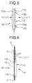
- Figure 3 is a partial, cross-sectional view taken along line III-III of Figure 2.
- Figure 4 is a side elevational view of the slide fastener as seen in the direction of arrow IV of Figure 2.
- Figure 5 is a partial, enlarged cross-section view taken along line V-V of Figure 2.
- Figure 6 is a side view as seen in the direction of arrow VI of Figure 2.
- Figure 7 is a rear view of the slide fastener portion shown in Figures 1 and 2.
- Figure 8 is an exploded perspective view of a bottom end stop according to the present invention.
- Figures 9 and 10 are a front view and a rear view, respectively, of an end portion of another slide fastener provided with a bottom end stop according to the present invention. In the drawings,
reference numeral 1 indicates a slide fastener including a pair of left andright stringer tapes 2 having their respective opposed inner longitudinal edges. Between the opposed inner edges there is defined agap 3. - In the embodiment shown, on and along their respective inner edges the
tapes 2 are provided with respective longitudinal reinforcingcords 4. - The inner edges of the
tapes 2 are in a per se known manner provided with respective longitudinal rows ofcoupling elements 5, such as metal teeth or injection-moulded teeth. - A bottom end stop according to the present invention, generally indicated 10, is fastened to the
stringer tapes 2 of the zipper, adjacent the bottom end of said rows ofcoupling elements 5. - The
bottom end stop 10 comprises two originally separate and distinct members, i.e. arivet member 11 and a corresponding backplate 12 (see in particular Figure 8). - In the embodiment shown in the drawings, the
rivet member 11 comprises aplate portion 11a, having a longitudinally elongated, substantially rectangular shape. Theplate portion 11a is provided on its inner surface with two integral protrudingpins 11b. Thesepins 11b are arranged at a predetermined interval longitudinally of theplate portion 11a. On the other hand, theback plate 12 has an elongated, substantially rectangular shape, as theplate portion 11a of therivet member 11. Theback plate 12 has two throughapertures 12a formed perpendicularly therethrough, and these throughapertures 12a are arranged at a predetermined interval longitudinally of theback plate 12. Thepins 11b of therivet member 11 is inserted through thecorresponding apertures 12a of thebackplate 12 and engaged therewith so that the pins may not be pulled off thebackplate 12. (See in particular Figures 3 and 8). Referring to Figure 8, in the embodiment shown thepins 11b have a substantially cylindrical proximal shank, ending with a substantially conical distal tip portion. - After passing through the through
aperture 12a ofbackplate 12, the parts of thepins 11b of therivet member 11 projecting beyond thebackplate 12 are pressed against thebackplate 12 for instance by beating and are thus plastically deformed. As an alternative, thepins 11b might be heat-deformable, so that thepins 11b have been deformed in such a manner that they will not be restored into the original shape permanently. With such deformation, the distal end of eachpin 11b is enlarged radially thereof to provide a bulged outline or shape which is greater than the corresponding throughaperture 12a, so thatpins 11b are prevented from coming off the throughapertures 12a. - Still referring to Figure 8, the
plate portion 11a of therivet member 11 has, in its face intended to be applied to thestringer tapes 2, a pair oflongitudinal grooves 11c. The pair ofgrooves 11c are disposed on the right and left opposed sides of theplate portion 11a with the twopins 11b interposed therebetween in such a way that thegrooves 11c extend longitudinally in parallel with theplate portion 11a. Thegrooves 11c are adapted to receive and firmly grip thereinforcement cords 4 of the stringer tapes. - Advantageously, the
plate portion 11a of therivet member 11 is also provided on its four corners with rows ofsawteeth 13, which extend along thelongitudinal grooves 11c longitudinally of theplate portion 11a. (See Figure 8.) These rows ofsawteeth 13 are adapted for gripping thecorresponding stringer tapes 2. However, it is not necessarily needed to provide sawteeth rows. - Conveniently, the
grooves 11c may each have at least oneprotruding ridge 11d extending transversely of theplate portion 11a in such a way to cross therectangular groove 11c. Preferably, a plurality of protrudingridges 11d are provided at predetermined intervals longitudinally of theplate portion 11a. Theseprotruding ridges 11d are adapted to bite the reinforcingcords 4 of thecorresponding stringer tapes 2. However, it is not necessarily needed to provide ridges. - In the embodiment shown in Figures 1 to 7, the
rivet member 11 and thebackplate 12 of thebottom stop 10 are fastened to stringertapes 2 in such a way that thepins 11b of therivet member 11 do not extend through thetapes 2. Instead, said pins extend through thegap 3 defined between the inner edges of thestringer tapes 2. Namely, thepins 11b extend perpendicularly of thestringer tapes 2 and are inserted through thegap 3. Thestringer tapes 2, and particularly the reinforcingcords 4 thereof, are firmly clasped between theplate portion 11a of therivet member 11 and the associatedbackplate 12. At this instant, since thelongitudinal reinforcing cord 4 of eachstringer tape 2 is received in the correspondinglongitudinal groove 11 provided in theplate portion 11a of therivet member 11; even if stresses are exerted tending to pullstringer tapes 2 apart from each other, thelongitudinal reinforcing cord 4 is firmly retained by the outer side edge of thelongitudinal groove 11c, so that thestringer tapes 2 are well prevented from being pulled out from between theplate portion 11a and thebackplate 12. Furthermore, since the rows ofsawteeth 13 provided on theplate portion 11a firmlygrip stringer tapes 2 and theprotruding ridges 11d provided on thelongitudinal grooves 11c bite the reinforcingcords 4; even if thestringer tapes 2 are subjected to forces tending to pull thestringer tapes 2 longitudinally thereof, thestringer tapes 2 are prevented from being pulled out from between theplate portion 11a and thebackplate 12. - In the embodiment shown in Figures 9 and 10, the
stringer tapes 2 at their bottom ends are provided with (at least one) respective through aperture (not visible in said Figures) and therivet member 11 has itspins 11b engaged through these apertures of thetapes 2, as well as through thecorresponding apertures 12a of thebackplate 12, in such a way that the bottom stop 10 as a whole transversely crosslinks the tapes. - The outer surface of the
rivet member 11 and/or that of thebackplate 12 may be used to apply thereto a trade name or a trade mark or the like. The general shape of themember 11 and/or thebackplate 12 may be varied in order to best accommodate a customer's desires for a particular logo. - Though in the embodiments illustrated in the drawings and described above the
rivet member 11 is provided with grooves, sawteeth and protruding ridges at the same time, in general the rivet member might be provided with only one or more of said features. Furthermore, the sawteeth and the ridges, if at all present, might extend in any direction parallel to the plate portion of the rivet member. - With the construction as mentioned above, when a bottom end stop according to the present invention is attached to a slide fastener, pressure can be applied evenly to deform the pin or pins of the rivet member, and there is no need to bend any portions of the fastening plate members thereof. Therefore, the bottom end stop is very firm and will never be easily broken.
- Although the description above contains many specificities, there should not be construed as limiting the scope of the invention but as merely providing illustrations of some of the presently preferred embodiments of this invention.
- Thus, the scope of the invention should be determined by the appended claims and their legal equivalents, rather than by the examples given.
Claims (8)
- A bottom end stop (10) for a slide fastener (1) comprising a pair of stringer tapes (2) defining a gap (3) therebetween and provided on their respective inner edges with respective longitudinal rows of coupling elements (5); the bottom end stop (10) comprising first and second fastening plate members (11a, 12) adapted to be fastened to the stringer tapes (2), one on each side of the slide fastener (1), adjacent the bottom end of said rows of coupling elements (5), astride the gap (3) between the tapes (2); said plate members (11a, 12) being connected with each other by at least one transverse connecting member (11b); characterised in that said first and second fastening plate members are a plate portion (11a) of a rivet member (11) and a backplate (12), respectively; the backplate (12) being provided with at least one through aperture (12a), the transverse connecting member (11b) being one integral protruding pin (11b) provided on the rivet member (11) and adapted to be engaged through said at least one aperture (12a) of the backplate (12) and to be permanently deformed beyond and against the backplate (12).
- A bottom end stop according to claim 1, wherein the rivet member (11) has a plurality of integral protruding pins (11b) and the backplate (12) has a corresponding plurality of through apertures (12a).
- A bottom end stop according to claim 1 or 2, for a slide fastener (1) in which the inner edges of the stringer tapes (2) are provided with respective longitudinal reinforcing cords (4), the plate portion (11a) of the rivet member (11) in its face intended to be applied to the tapes (2) being provided with a pair of parallel grooves (11c) adapted to receive and grip the reinforcing cords (4) of the stringer tapes (2).
- A bottom end stop according to any of the preceding claims, wherein the plate portion (11a) of the rivet member (11) is provided with rows of sawteeth (13) for gripping the stringer tapes (2).
- A bottom end stop according to any of the preceding claims, wherein said rivet members (11) is provided with at least one protruding ridge (11d) adapted to bite the reinforcing cord(s) (4) of the stringer tape(s) (2).
- A slide fastener (1) provided with a bottom end stop (10) according to any of the preceding claims.
- A slide fastener according to claim 6, wherein the backplate (12) and the rivet member (11) are fastened to the stringer tapes (2) in such a way that the pin or pins (11b) of the rivet member (11) extend through the gap (3) between the stringer tapes (2).
- A slide fastener according to claim 6, wherein the stringer tapes (2) at their bottom ends are provided with at least one respective through aperture, and the rivet member (11) has at least two integral pins (11b) engaged through said apertures of the tapes (2) and the corresponding apertures (12a) of the backplate (12).
Applications Claiming Priority (1)
| Application Number | Priority Date | Filing Date | Title |
|---|---|---|---|
| IT000659A ITTO20060659A1 (en) | 2006-09-15 | 2006-09-15 | TRAVEL BASE STOP FOR A LAMPO HINGE, AND A ZIPPER HINGE INCLUDING SUCH A STOP OF THE RACING BASE. |
Publications (3)
| Publication Number | Publication Date |
|---|---|
| EP1900298A2 true EP1900298A2 (en) | 2008-03-19 |
| EP1900298A3 EP1900298A3 (en) | 2012-12-05 |
| EP1900298B1 EP1900298B1 (en) | 2014-08-06 |
Family
ID=38868962
Family Applications (1)
| Application Number | Title | Priority Date | Filing Date |
|---|---|---|---|
| EP07116141.8A Not-in-force EP1900298B1 (en) | 2006-09-15 | 2007-09-11 | A bottom end stop for a slide fastener, and a slide fastener comprising such a bottom end stop |
Country Status (8)
| Country | Link |
|---|---|
| US (1) | US20080066269A1 (en) |
| EP (1) | EP1900298B1 (en) |
| JP (1) | JP5019115B2 (en) |
| KR (1) | KR100857684B1 (en) |
| CN (1) | CN100508817C (en) |
| ES (1) | ES2511773T3 (en) |
| IT (1) | ITTO20060659A1 (en) |
| TW (1) | TWI365725B (en) |
Cited By (3)
| Publication number | Priority date | Publication date | Assignee | Title |
|---|---|---|---|---|
| AT13288U1 (en) * | 2011-04-29 | 2013-10-15 | Coats Opti Germany Gmbh | Finishing cap for making dividable zippers |
| EP2885997A1 (en) * | 2013-12-19 | 2015-06-24 | YKK Corporation | End stop, slide fastener and ornamental fastener |
| EP2622985A4 (en) * | 2010-09-28 | 2017-08-16 | YKK Corporation | Slide fastener and production method for slide fastener stop |
Families Citing this family (6)
| Publication number | Priority date | Publication date | Assignee | Title |
|---|---|---|---|---|
| GB0920212D0 (en) | 2009-11-18 | 2010-01-06 | Ykk Europ Ltd | Bottom stop improvement for a zip fastener |
| CN101878982A (en) * | 2010-06-08 | 2010-11-10 | 江苏博豪拉链制造有限公司 | Zipper with firm pin box block |
| WO2013013716A1 (en) * | 2011-07-27 | 2013-01-31 | Ykk Corporation | Stop for a slide fastener, and a method for the manufacture thereof |
| TWI480002B (en) * | 2011-07-27 | 2015-04-11 | Ykk Corp | The method of manufacturing the zipper and zipper |
| TW201711594A (en) * | 2015-07-31 | 2017-04-01 | 里莫華有限公司 | Piece of baggage including a stopper means and a method for manufacturing the same |
| CN110071465A (en) * | 2019-05-22 | 2019-07-30 | 湖南三一港口设备有限公司 | Harness means of defence, device and its manufacturing process |
Citations (2)
| Publication number | Priority date | Publication date | Assignee | Title |
|---|---|---|---|---|
| DE7137952U (en) | 1971-10-07 | 1972-01-20 | Opti-Holding Ag | Zipper tape |
| JPS49105307U (en) | 1972-12-29 | 1974-09-10 |
Family Cites Families (12)
| Publication number | Priority date | Publication date | Assignee | Title |
|---|---|---|---|---|
| US1657385A (en) * | 1926-06-24 | 1928-01-24 | John B Freysinger | Flexible closure |
| US2312045A (en) * | 1941-02-19 | 1943-02-23 | Louis H Morin | Bottom stop for separable fasteners and the method of producing the same |
| US2573058A (en) * | 1945-08-31 | 1951-10-30 | Conmar Prod Corp | Releasing end stop nonseparable slide fastener |
| JPS5989017U (en) * | 1982-12-06 | 1984-06-16 | ワイケイケイ株式会社 | Lower stop for slide fastener |
| GB2180591B (en) * | 1985-09-18 | 1989-04-26 | James Trevor Jones | End terminating means for slide fasteners |
| JPH0634504U (en) * | 1992-10-19 | 1994-05-10 | 吉田工業株式会社 | Synthetic resin stopper |
| JPH08313A (en) * | 1994-06-27 | 1996-01-09 | Ykk Kk | Slide fastener |
| JP3733343B2 (en) | 2002-05-20 | 2006-01-11 | Ykk株式会社 | Separation insert for slide fastener |
| JP3901662B2 (en) * | 2003-04-25 | 2007-04-04 | Ykk株式会社 | Airtight waterproof slide fastener |
| CN2657442Y (en) * | 2003-11-05 | 2004-11-24 | 上富拉链机械股份有限公司 | Zipper thermoplastic clip teeth upper stop and lower stop structure |
| JP4062620B2 (en) * | 2003-11-20 | 2008-03-19 | Ykk株式会社 | Slide fastener fastener |
| CN100411563C (en) * | 2005-09-21 | 2008-08-20 | 钟砚宝 | Nylon slide fastener, and its stop button forming method and forming device |
-
2006
- 2006-09-15 IT IT000659A patent/ITTO20060659A1/en unknown
-
2007
- 2007-08-31 TW TW096132669A patent/TWI365725B/en not_active IP Right Cessation
- 2007-09-11 ES ES07116141.8T patent/ES2511773T3/en active Active
- 2007-09-11 EP EP07116141.8A patent/EP1900298B1/en not_active Not-in-force
- 2007-09-13 JP JP2007267185A patent/JP5019115B2/en not_active Expired - Fee Related
- 2007-09-14 US US11/901,257 patent/US20080066269A1/en not_active Abandoned
- 2007-09-14 CN CNB2007101515077A patent/CN100508817C/en active Active
- 2007-09-14 KR KR1020070093536A patent/KR100857684B1/en not_active Expired - Fee Related
Patent Citations (2)
| Publication number | Priority date | Publication date | Assignee | Title |
|---|---|---|---|---|
| DE7137952U (en) | 1971-10-07 | 1972-01-20 | Opti-Holding Ag | Zipper tape |
| JPS49105307U (en) | 1972-12-29 | 1974-09-10 |
Cited By (6)
| Publication number | Priority date | Publication date | Assignee | Title |
|---|---|---|---|---|
| EP2622985A4 (en) * | 2010-09-28 | 2017-08-16 | YKK Corporation | Slide fastener and production method for slide fastener stop |
| AT13288U1 (en) * | 2011-04-29 | 2013-10-15 | Coats Opti Germany Gmbh | Finishing cap for making dividable zippers |
| EP2885997A1 (en) * | 2013-12-19 | 2015-06-24 | YKK Corporation | End stop, slide fastener and ornamental fastener |
| CN104720213A (en) * | 2013-12-19 | 2015-06-24 | Ykk株式会社 | End stop, slide fastener and ornamental fastener |
| CN104720213B (en) * | 2013-12-19 | 2017-10-13 | Ykk株式会社 | Stop part, slide fastener, decoration slide fastener |
| US9936775B2 (en) | 2013-12-19 | 2018-04-10 | Ykk Corporation | End stop, slide fastener and ornamental fastener |
Also Published As
| Publication number | Publication date |
|---|---|
| CN101143043A (en) | 2008-03-19 |
| CN100508817C (en) | 2009-07-08 |
| HK1110754A1 (en) | 2008-07-25 |
| TWI365725B (en) | 2012-06-11 |
| ES2511773T3 (en) | 2014-10-23 |
| KR100857684B1 (en) | 2008-09-08 |
| US20080066269A1 (en) | 2008-03-20 |
| ITTO20060659A1 (en) | 2008-03-16 |
| EP1900298A3 (en) | 2012-12-05 |
| JP5019115B2 (en) | 2012-09-05 |
| TW200824593A (en) | 2008-06-16 |
| EP1900298B1 (en) | 2014-08-06 |
| JP2008068110A (en) | 2008-03-27 |
| KR20080025337A (en) | 2008-03-20 |
Similar Documents
| Publication | Publication Date | Title |
|---|---|---|
| EP1900298B1 (en) | A bottom end stop for a slide fastener, and a slide fastener comprising such a bottom end stop | |
| US20180220763A1 (en) | Luggage piece with stopper device | |
| EP2705768B1 (en) | Slide fastener | |
| CN103209609A (en) | Sliding fastener | |
| CA1216143A (en) | Bottom stop for slide fasteners | |
| EP1236413A2 (en) | Top end stop for slide fastener | |
| EP1537800A1 (en) | Concave buckle for strap | |
| EP0689780A2 (en) | Slide fastener | |
| JPH11332616A (en) | Fastener tape separable bottom stop | |
| DE112014006879T5 (en) | Slider for a zipper | |
| EP0931002B1 (en) | Tag pin assembly | |
| KR0152166B1 (en) | Slider for slide fastener | |
| CN116113343B (en) | Fastener element and fastener element tape | |
| EP2737148B1 (en) | Snap feature providing component attachment | |
| US20100284761A1 (en) | Press Type Fastener | |
| US4878275A (en) | Separable slide fastener | |
| EP0103890B2 (en) | A fastening for a garment | |
| HK1110754B (en) | A bottom end stop for a slide fastener, and a slide fastener comprising such a bottom end stop | |
| US20240298755A1 (en) | Slide fastener elements, fastener stringers, and fastener chain | |
| EP0041237A1 (en) | Bridge top stop for slide fasteners | |
| EP2281717A2 (en) | Tightening cord provided with connecting means | |
| CN204306181U (en) | Self-locking zipper slider | |
| US11083254B2 (en) | Slider for slide fastener | |
| CN211483212U (en) | Bracelet fastening mechanism and bracelet | |
| JP6297382B2 (en) | Slide fastener puller |
Legal Events
| Date | Code | Title | Description |
|---|---|---|---|
| PUAI | Public reference made under article 153(3) epc to a published international application that has entered the european phase |
Free format text: ORIGINAL CODE: 0009012 |
|
| AK | Designated contracting states |
Kind code of ref document: A2 Designated state(s): AT BE BG CH CY CZ DE DK EE ES FI FR GB GR HU IE IS IT LI LT LU LV MC MT NL PL PT RO SE SI SK TR |
|
| AX | Request for extension of the european patent |
Extension state: AL BA HR MK YU |
|
| RIN1 | Information on inventor provided before grant (corrected) |
Inventor name: YONEOKA, MORIMASA C/O YKK EUROPE LIMITED |
|
| RIC1 | Information provided on ipc code assigned before grant |
Ipc: A44B 19/36 20060101AFI20120830BHEP |
|
| PUAL | Search report despatched |
Free format text: ORIGINAL CODE: 0009013 |
|
| RIC1 | Information provided on ipc code assigned before grant |
Ipc: A44B 19/36 20060101AFI20121015BHEP |
|
| AK | Designated contracting states |
Kind code of ref document: A3 Designated state(s): AT BE BG CH CY CZ DE DK EE ES FI FR GB GR HU IE IS IT LI LT LU LV MC MT NL PL PT RO SE SI SK TR |
|
| AX | Request for extension of the european patent |
Extension state: AL BA HR MK RS |
|
| 17P | Request for examination filed |
Effective date: 20130530 |
|
| RBV | Designated contracting states (corrected) |
Designated state(s): AT BE BG CH CY CZ DE DK EE ES FI FR GB GR HU IE IS IT LI LT LU LV MC MT NL PL PT RO SE SI SK TR |
|
| AKX | Designation fees paid |
Designated state(s): DE ES FR GB IT TR |
|
| GRAP | Despatch of communication of intention to grant a patent |
Free format text: ORIGINAL CODE: EPIDOSNIGR1 |
|
| INTG | Intention to grant announced |
Effective date: 20140225 |
|
| GRAS | Grant fee paid |
Free format text: ORIGINAL CODE: EPIDOSNIGR3 |
|
| GRAA | (expected) grant |
Free format text: ORIGINAL CODE: 0009210 |
|
| RIN1 | Information on inventor provided before grant (corrected) |
Inventor name: YONEOKA, MORIMASA |
|
| AK | Designated contracting states |
Kind code of ref document: B1 Designated state(s): DE ES FR GB IT TR |
|
| REG | Reference to a national code |
Ref country code: GB Ref legal event code: FG4D |
|
| REG | Reference to a national code |
Ref country code: DE Ref legal event code: R096 Ref document number: 602007037956 Country of ref document: DE Effective date: 20140918 |
|
| REG | Reference to a national code |
Ref country code: ES Ref legal event code: FG2A Ref document number: 2511773 Country of ref document: ES Kind code of ref document: T3 Effective date: 20141023 |
|
| REG | Reference to a national code |
Ref country code: DE Ref legal event code: R097 Ref document number: 602007037956 Country of ref document: DE |
|
| PLBE | No opposition filed within time limit |
Free format text: ORIGINAL CODE: 0009261 |
|
| STAA | Information on the status of an ep patent application or granted ep patent |
Free format text: STATUS: NO OPPOSITION FILED WITHIN TIME LIMIT |
|
| 26N | No opposition filed |
Effective date: 20150507 |
|
| REG | Reference to a national code |
Ref country code: FR Ref legal event code: PLFP Year of fee payment: 10 |
|
| REG | Reference to a national code |
Ref country code: FR Ref legal event code: PLFP Year of fee payment: 11 |
|
| REG | Reference to a national code |
Ref country code: FR Ref legal event code: PLFP Year of fee payment: 12 |
|
| PGFP | Annual fee paid to national office [announced via postgrant information from national office to epo] |
Ref country code: IT Payment date: 20190917 Year of fee payment: 13 Ref country code: DE Payment date: 20190827 Year of fee payment: 13 Ref country code: FR Payment date: 20190815 Year of fee payment: 13 Ref country code: TR Payment date: 20190909 Year of fee payment: 13 |
|
| PGFP | Annual fee paid to national office [announced via postgrant information from national office to epo] |
Ref country code: GB Payment date: 20190912 Year of fee payment: 13 |
|
| PGFP | Annual fee paid to national office [announced via postgrant information from national office to epo] |
Ref country code: ES Payment date: 20191002 Year of fee payment: 13 |
|
| REG | Reference to a national code |
Ref country code: DE Ref legal event code: R119 Ref document number: 602007037956 Country of ref document: DE |
|
| GBPC | Gb: european patent ceased through non-payment of renewal fee |
Effective date: 20200911 |
|
| PG25 | Lapsed in a contracting state [announced via postgrant information from national office to epo] |
Ref country code: DE Free format text: LAPSE BECAUSE OF NON-PAYMENT OF DUE FEES Effective date: 20210401 Ref country code: FR Free format text: LAPSE BECAUSE OF NON-PAYMENT OF DUE FEES Effective date: 20200930 |
|
| PG25 | Lapsed in a contracting state [announced via postgrant information from national office to epo] |
Ref country code: GB Free format text: LAPSE BECAUSE OF NON-PAYMENT OF DUE FEES Effective date: 20200911 |
|
| PG25 | Lapsed in a contracting state [announced via postgrant information from national office to epo] |
Ref country code: IT Free format text: LAPSE BECAUSE OF NON-PAYMENT OF DUE FEES Effective date: 20200911 |
|
| REG | Reference to a national code |
Ref country code: ES Ref legal event code: FD2A Effective date: 20220117 |
|
| PG25 | Lapsed in a contracting state [announced via postgrant information from national office to epo] |
Ref country code: ES Free format text: LAPSE BECAUSE OF NON-PAYMENT OF DUE FEES Effective date: 20200912 |
|
| PG25 | Lapsed in a contracting state [announced via postgrant information from national office to epo] |
Ref country code: TR Free format text: LAPSE BECAUSE OF NON-PAYMENT OF DUE FEES Effective date: 20200911 |