EP1900297A1 - Slider for fluid tight slide fastener - Google Patents
Slider for fluid tight slide fastener Download PDFInfo
- Publication number
- EP1900297A1 EP1900297A1 EP07253671A EP07253671A EP1900297A1 EP 1900297 A1 EP1900297 A1 EP 1900297A1 EP 07253671 A EP07253671 A EP 07253671A EP 07253671 A EP07253671 A EP 07253671A EP 1900297 A1 EP1900297 A1 EP 1900297A1
- Authority
- EP
- European Patent Office
- Prior art keywords
- slider
- guide
- plate
- guide plate
- trailing
- Prior art date
- Legal status (The legal status is an assumption and is not a legal conclusion. Google has not performed a legal analysis and makes no representation as to the accuracy of the status listed.)
- Granted
Links
Images




Classifications
-
- A—HUMAN NECESSITIES
- A44—HABERDASHERY; JEWELLERY
- A44B—BUTTONS, PINS, BUCKLES, SLIDE FASTENERS, OR THE LIKE
- A44B19/00—Slide fasteners
- A44B19/24—Details
- A44B19/26—Sliders
-
- Y—GENERAL TAGGING OF NEW TECHNOLOGICAL DEVELOPMENTS; GENERAL TAGGING OF CROSS-SECTIONAL TECHNOLOGIES SPANNING OVER SEVERAL SECTIONS OF THE IPC; TECHNICAL SUBJECTS COVERED BY FORMER USPC CROSS-REFERENCE ART COLLECTIONS [XRACs] AND DIGESTS
- Y10—TECHNICAL SUBJECTS COVERED BY FORMER USPC
- Y10T—TECHNICAL SUBJECTS COVERED BY FORMER US CLASSIFICATION
- Y10T24/00—Buckles, buttons, clasps, etc.
- Y10T24/25—Zipper or required component thereof
- Y10T24/2514—Zipper or required component thereof with distinct member for sealing surfaces
-
- Y—GENERAL TAGGING OF NEW TECHNOLOGICAL DEVELOPMENTS; GENERAL TAGGING OF CROSS-SECTIONAL TECHNOLOGIES SPANNING OVER SEVERAL SECTIONS OF THE IPC; TECHNICAL SUBJECTS COVERED BY FORMER USPC CROSS-REFERENCE ART COLLECTIONS [XRACs] AND DIGESTS
- Y10—TECHNICAL SUBJECTS COVERED BY FORMER USPC
- Y10T—TECHNICAL SUBJECTS COVERED BY FORMER US CLASSIFICATION
- Y10T24/00—Buckles, buttons, clasps, etc.
- Y10T24/25—Zipper or required component thereof
- Y10T24/2561—Slider having specific configuration, construction, adaptation, or material
-
- Y—GENERAL TAGGING OF NEW TECHNOLOGICAL DEVELOPMENTS; GENERAL TAGGING OF CROSS-SECTIONAL TECHNOLOGIES SPANNING OVER SEVERAL SECTIONS OF THE IPC; TECHNICAL SUBJECTS COVERED BY FORMER USPC CROSS-REFERENCE ART COLLECTIONS [XRACs] AND DIGESTS
- Y10—TECHNICAL SUBJECTS COVERED BY FORMER USPC
- Y10T—TECHNICAL SUBJECTS COVERED BY FORMER US CLASSIFICATION
- Y10T24/00—Buckles, buttons, clasps, etc.
- Y10T24/25—Zipper or required component thereof
- Y10T24/2561—Slider having specific configuration, construction, adaptation, or material
- Y10T24/2582—Slider having specific configuration, construction, adaptation, or material having specific contour or arrangement of converging channel, separator island, or wing
-
- Y—GENERAL TAGGING OF NEW TECHNOLOGICAL DEVELOPMENTS; GENERAL TAGGING OF CROSS-SECTIONAL TECHNOLOGIES SPANNING OVER SEVERAL SECTIONS OF THE IPC; TECHNICAL SUBJECTS COVERED BY FORMER USPC CROSS-REFERENCE ART COLLECTIONS [XRACs] AND DIGESTS
- Y10—TECHNICAL SUBJECTS COVERED BY FORMER USPC
- Y10T—TECHNICAL SUBJECTS COVERED BY FORMER US CLASSIFICATION
- Y10T24/00—Buckles, buttons, clasps, etc.
- Y10T24/25—Zipper or required component thereof
- Y10T24/2561—Slider having specific configuration, construction, adaptation, or material
- Y10T24/2582—Slider having specific configuration, construction, adaptation, or material having specific contour or arrangement of converging channel, separator island, or wing
- Y10T24/2584—Spaced segments of each wall of channel supported by different wings
-
- Y—GENERAL TAGGING OF NEW TECHNOLOGICAL DEVELOPMENTS; GENERAL TAGGING OF CROSS-SECTIONAL TECHNOLOGIES SPANNING OVER SEVERAL SECTIONS OF THE IPC; TECHNICAL SUBJECTS COVERED BY FORMER USPC CROSS-REFERENCE ART COLLECTIONS [XRACs] AND DIGESTS
- Y10—TECHNICAL SUBJECTS COVERED BY FORMER USPC
- Y10T—TECHNICAL SUBJECTS COVERED BY FORMER US CLASSIFICATION
- Y10T24/00—Buckles, buttons, clasps, etc.
- Y10T24/25—Zipper or required component thereof
- Y10T24/2561—Slider having specific configuration, construction, adaptation, or material
- Y10T24/2588—Slider having specific configuration, construction, adaptation, or material including means for attaching components of slider together
-
- Y—GENERAL TAGGING OF NEW TECHNOLOGICAL DEVELOPMENTS; GENERAL TAGGING OF CROSS-SECTIONAL TECHNOLOGIES SPANNING OVER SEVERAL SECTIONS OF THE IPC; TECHNICAL SUBJECTS COVERED BY FORMER USPC CROSS-REFERENCE ART COLLECTIONS [XRACs] AND DIGESTS
- Y10—TECHNICAL SUBJECTS COVERED BY FORMER USPC
- Y10T—TECHNICAL SUBJECTS COVERED BY FORMER US CLASSIFICATION
- Y10T24/00—Buckles, buttons, clasps, etc.
- Y10T24/26—Slit closing means including guides on opposite edges of slit and slidable bridging component
- Y10T24/264—Slit closing means including guides on opposite edges of slit and slidable bridging component including structure linking and allowing variations in separation between opposite-guide-contacting portions of component
Definitions
- This invention relates to a slider for a fluid tight fastener of the type described in EP-A-1057423 and EP-A-1175842 .
- a coil like continuous coupling member is sewn onto a tape surface near an edge of the tape.
- the other surface of the tape is coated with a fluid proof layer which extends beyond the edge of the tape to form a sealing lip.
- the sealing lips of the fluid proof layers abut to form a seal.
- Such fasteners can provide a reasonably good seal against liquids or gasses, depending on various factors such as the design of the sealing lips of the fluid proof layers, the extent to which they are urged together by the coupled elements and the extent of flexing of the fastener in use.
- the slider shown in EP-A-1057423 and EP-A-1175842 incorporates a guide plate or "guide flange" in the form of a thin blade which projects from the wedge which joins the upper and lower plates of the slider.
- This guide plate extends between the outer ends of the coupling elements and the sealing lips.
- the guide plate creates upper and lower paths within the slider and serves to ensure more accurate alignment of the coupling elements as they are brought together and enables greater pressure to be exerted on the sealing lips whilst keeping them aligned.
- the slider shown in EP-A-1057423 and EP-A-1175842 has been made of three parts, with the guide plate being formed separately and sandwiched between the upper and lower plates and guide posts. This adds significantly to the cost of the production process.
- a first aspect of the present invention provides a slider for a fluid tight slide fastener, the slider having upper and lower plates joined together by a guide post and a guide plate formed on the guide post to cooperate with the upper and lower plates to guide the coupling elements and sealing lips of the slide fastener, wherein the slider is integrally formed.
- the slider may be die cast or moulded as a single, integral member of metal or plastics material.
- the trailing portion of the guide plate is joined to the upper plate by a web which extends from the guide post.
- the web may extend to the trailing edge of the guide plate.
- the forward part of the guide plate is thickened relative to the trailing end.
- the outer edge of the thickened part may be chamfered.
- the underside of the guide plate may be substantially flat, forming with the lower plate a guide channel for the coupling elements.
- the underside of the trailing end may be thickened where it joins the guide post.
- the trailing end of the upper plate has downwardly projecting guide flanges extending perpendicularly from the edge of the upper plate.
- the guide flanges may be wedge shaped in cross section, to form a guide channel which is narrowed at its upper region, near the upper plate.
- Slider 1 has upper and lower plates 2, 3 with a bridge 4 formed on the upper plate 2 for receiving a slider puller (not shown).
- Upper and lower guide post halves 5, 6 depend from the upper and lower plates and sandwich a guide plate 7 between them.
- side flanges 8, 9 depend from the left and right side edges of the upper and lower plates 2, 3 at the trailing ends of the plates so as to extend longitudinally of the slider 1.
- the side flanges 8, 9 serve to couple the coupling elements 10 and urge sealing lips 11 of the fastener into abutting engagement with each other.
- the fluid tight slide fastener comprises tapes 12 with coil like coupling elements 10 mounted on one surface 13 near the outer edge 14 of the respective tapes.
- the coating 15 has sealing lips 11 formed integrally therewith, which sealing lips 11 are guided by the guide plate 7 and upper plate 2 into an abutting, sealing position as the fastener elements 10 are coupled together.
- a reinforcing tape 17 is provided on the underneath surface of the tapes 12.
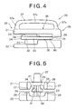
- FIGS. 4 and 5 show a slider 20 in accordance with the invention for a fluid tight slide fastener of the type described above.
- the slider has parallel upper and lower guide plates 21, 22, and a guide post 23 joining both the guide plates 21, 22.
- a guide plate 24 is disposed between the upper plate 21 and the lower plate 22 and spaced from the upper and lower plates 21, 22, respectively.
- the guide plate 24 is joined with the guide post 23.
- the guide plate 24 extends out from the guide post 23 towards the forward and trailing ends 25, 26 of the slider 20.
- the guide plate 24 also extends toward opposed left and right sides of the guide post 23.
- the upper and lower guide plates 21, 22, guide post 23 and guide plate 24 are integrally formed, that is formed of a single unitary piece. They may be formed of metal by die-casting or of plastics by moulding, for example.
- a bridge 37 for attaching a puller (not shown) is also integrally formed on the upper surface 38 of the upper plate 21.
- the bridge 37 includes a front leg 37a mounted on the front end 25 of the slider 1, a rear leg 37b mounted on the rear end 26 of the slider 1 and a bridge proper 37c connecting the front and rear legs 37a, 37b at their respective upper ends.
- Other structures for attaching a puller may be used, as known in the art.
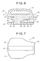
- the upper and lower plates 21, 22 are of generally the same outline or shape, as viewed in a plan. As seen in Figure 7, both the plates 21, 22 taper towards the trailing end 26. Upper and lower side flanges 27, 28 depend from the left and right opposed sides of the respective upper and lower plates 21, 22 over the tapering portion of the plates 21, 22.
- the upper flange 27 is formed so as to project from the upper plate 21 toward the lower plate 22 and to stand at a right angle relative to the upper plate 21, while the lower flange 28 is formed so as to project from the lower plate 22 toward the upper plate 21 and to stand at a right angle relative to the lower plate 22.
- the lower flange 28 serves to urge the coupling elements 10 of the opposed tapes 12 toward each other and into engagement when the slider 20 moves forward.
- the upper flanges 27 serve to urge the sealing lips 11 toward each other and into abutting engagement with each other, when the slider 20 moves forward. Although the lips 11 would be pulled together as the coupling elements 10 are engaged, the side flanges 27 will reduce the strain on the coupling elements 10 and their connection to the tapes 12, and also serve to ensure consistent orientation of the sealing lips 11.
- the guide plate 24 is a particular feature of this invention. Forming the upper and lower plates 21, 22 guide post 23 and guide plate 24 as an integral unit serves to strengthen the slider 20. We also enhance the strength by increasing the thickness of the guide plate 24 and providing a greater mating area with the upper plate 21.
- the guide post 23 has a generally rectangular cross-section with a tapered end 23a, ending in a trailing edge 39 of the guide post 23.
- a web 29 joins the trailing portion 30 of the guide plate 24 to the upper plate 21.
- Web 29 tapers in thickness from the guide post 23 to the trailing edge 31 of the guide plate 24, to provide a smooth transition path for the sealing lips as they are urged together.
- the web 29 extends from the guide post 23 to the trailing edge 31 of the guide plate 24. However, the web 29 may stop short of the trailing edge 31.
- the guide plate 24 includes a forward portion 32 extending from the guide post 23 toward the forward end 25 of the slider 20, a tailing portion 30 extending from the guide post 23 toward the tailing end 26 of the slider 20 and a side portion 33 extending from the guide post 23 sideways or laterally of the slider 20
- the forward portion 32 and the side portion 33 of the guide plate 24 are thickened, being thicker than the trailing portion 30 over a region extending approximately from the trailing edge 39 of the guide post 23 toward the forward end 25 of the slider 20.
- the outer edge of the forward portion 32 and the side portion 33 is tapered in thickness, and has a chamfer 34.
- the chamfer 34 is formed on the upper surface of the guide plate 24 and is disposed so as to face the upper plate 21.
- a fillet 35 is provided on the under side of the trailing portion 30 of the guide plate 24 at the junction with the trailing edge 39 of the guide post 23. The fillet 35 extends from the trailing edge 39 of the guide post 23 toward the trailing edge 31 of the guide plate 24 and is tapered in thickness in that direction.
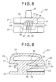
- FIGS 8 to 10 show a second embodiment of the invention, similar to the embodiment of Figures 4 to 7 and like parts are given like reference numerals.
- the web 29 of the previous embodiment is omitted.
- the thickness of the forward portion 32 is continued rearward past the trailing edge 39 of the guide post 23 and tapers down in thickness to a trailing edge 31' which is thinner than the forward portion 32 to thus form on the trailing portion 30 of the guide plate 24 a trailing surface 36 which slants down toward the trailing edge 31' of the guide plate 24.
- the opposed lateral sides of the trailing surface 36 merge in the chamfer 34 provided on the forward and side portions 32, 33.
- On the trailing portion 30 of the guide plate 24 is formed a sticklike nose portion 30a extending from the trailing surface 36 toward the trailing end 26 of the slider 20.
- fillets 40 between the upper side flanges 27 and the upper plate 21 to form an outlet mouth 35 at the trailing end 26 of the slider 20 which is tapered inwardly from the plane of the fastener coating layer 15 (the bottom edge of the side flange 27) towards the upper plate 23.
- the fillets serve to guide the sealing lips of the slide fastener and may be shaped to match the upper surface of the sealing lips 11.
- FIG. 10 Also seen in Figure 10 is a shallow platform 41 on the upper surface 42 of the lower plate 22.
- the shallow platform 41 serves to help orient in a suitable direction the posture that the coiled coupling elements 10 assume when coupled, as known in the art.
- Figures 11 and 12 show a third embodiment of the present invention.
- the third embodiment is similar to the second embodiment shown in Figures 8 through 10. So, parts which are similar to those of the second embodiment shown in Figures 8 through 10 are also denoted by the same reference numerals in Figures 11 and 12 showing the third embodiment.
- the trailing surface 36 formed on the trailing portion 30 of the guide plate 24 extends to the trailing edge 31 of the guide plate 24. Furthermore, the trailing portion 30 tapers in width or lateral dimension towards the trailing end 26 of the slider 1, thus presenting a wedge-like shape as a whole. This ensures that the sealing lips 11 can pass smoothly through the slider 1 during the movement of the slider 1, thereby mitigating frictional resistance caused by the sealing lips' sliding movement against the guide plate 24.
Landscapes
- Slide Fasteners (AREA)
Abstract
Description
- This invention relates to a slider for a fluid tight fastener of the type described in
EP-A-1057423 andEP-A-1175842 . A coil like continuous coupling member is sewn onto a tape surface near an edge of the tape. The other surface of the tape is coated with a fluid proof layer which extends beyond the edge of the tape to form a sealing lip. When the coupling members of adjacent tapes are engaged, the sealing lips of the fluid proof layers abut to form a seal. Such fasteners can provide a reasonably good seal against liquids or gasses, depending on various factors such as the design of the sealing lips of the fluid proof layers, the extent to which they are urged together by the coupled elements and the extent of flexing of the fastener in use. - The slider shown in
EP-A-1057423 andEP-A-1175842 incorporates a guide plate or "guide flange" in the form of a thin blade which projects from the wedge which joins the upper and lower plates of the slider. This guide plate extends between the outer ends of the coupling elements and the sealing lips. Thus the guide plate creates upper and lower paths within the slider and serves to ensure more accurate alignment of the coupling elements as they are brought together and enables greater pressure to be exerted on the sealing lips whilst keeping them aligned. - In practice, the slider shown in
EP-A-1057423 andEP-A-1175842 has been made of three parts, with the guide plate being formed separately and sandwiched between the upper and lower plates and guide posts. This adds significantly to the cost of the production process. - Thus a first aspect of the present invention provides a slider for a fluid tight slide fastener, the slider having upper and lower plates joined together by a guide post and a guide plate formed on the guide post to cooperate with the upper and lower plates to guide the coupling elements and sealing lips of the slide fastener, wherein the slider is integrally formed. In particular the slider may be die cast or moulded as a single, integral member of metal or plastics material. By integrally forming the slider we are able to strengthen the slider, and in particular in the region between the upper plate and the guide plate where the slider parts are subject to greater separation forces as the slider is pulled along the fastener to urge the sealing lips together. This substantially reduces the cost of the production process and also leads to an improvement in product quality because of the avoidance of any misalignment or other errors which may arise in an assembly process.
- A difficulty with the prior art slider design was the use of a relatively thin guide plate which extended a relatively long distance from the guide post and so was unsupported. This could not be reliably moulded as an integral part of the slider.
- In another feature of the invention, the trailing portion of the guide plate is joined to the upper plate by a web which extends from the guide post. The web may extend to the trailing edge of the guide plate.
- In another feature of the invention, the forward part of the guide plate is thickened relative to the trailing end. The outer edge of the thickened part may be chamfered.
- The underside of the guide plate may be substantially flat, forming with the lower plate a guide channel for the coupling elements. The underside of the trailing end may be thickened where it joins the guide post.
- In one embodiment, the trailing end of the upper plate has downwardly projecting guide flanges extending perpendicularly from the edge of the upper plate. In another embodiment, the guide flanges may be wedge shaped in cross section, to form a guide channel which is narrowed at its upper region, near the upper plate.
- Other aspects and preferred features of the invention will be apparent from the following description and the accompanying claims.
- The invention will be further described by way of example with reference to the accompanying drawings in which:
- Figure 1 is a side view of a prior art slider.
- Figure 2 is a plan view of the slider of Figure 1.
- Figure 3 is an end view of the slider of Figures 1 and 2, on a slider fastener.
- Figure 4 is a side view of a slider forming a first embodiment of the invention.
- Figure 5 is a trailing end view of the slider of Figure 4.
- Figure 6 is a longitudinal cross-section of the slider of Figure 4.
- Figure 7 is a plan view of the slider of Figure 4.
- Figure 8 is a trailing end view of a second embodiment of the invention.
- Figure 9 is a longitudinal cross-section view through the embodiment of Figure 8.
- Figure 10 is a perspective view of the embodiment of Figure 8 with an upper plate cut away.
- Figure 11 is a longitudinal cross-sectional view of a slider according to a third embodiment of the present invention.
- Figure 12 is a cross-sectional view taken on line A-A of Figure 11.
- Referring to Figures 1 and 2, these show a side view and plan view of a
prior art slider 1.Slider 1 has upper andlower plates bridge 4 formed on theupper plate 2 for receiving a slider puller (not shown). Upper and lowerguide post halves guide plate 7 between them. As seen in Figure 3,side flanges lower plates slider 1. When theslider 1 moves forward, theside flanges coupling elements 10 and urgesealing lips 11 of the fastener into abutting engagement with each other. As also illustrated in Figure 3, the fluid tight slide fastener comprisestapes 12 with coil likecoupling elements 10 mounted on onesurface 13 near theouter edge 14 of the respective tapes. Afluid proof coating 15, such as a rubber, elastomer or thermoplastics material, is provided on the other,upper surface 16. Thecoating 15 has sealinglips 11 formed integrally therewith, which sealinglips 11 are guided by theguide plate 7 andupper plate 2 into an abutting, sealing position as thefastener elements 10 are coupled together. A reinforcingtape 17 is provided on the underneath surface of thetapes 12. - Referring to Figures 4 and 5, these drawings show a
slider 20 in accordance with the invention for a fluid tight slide fastener of the type described above. The slider has parallel upper andlower guide plates guide post 23 joining both theguide plates guide plate 24 is disposed between theupper plate 21 and thelower plate 22 and spaced from the upper andlower plates guide plate 24 is joined with theguide post 23. As shown in Figure 4, theguide plate 24 extends out from theguide post 23 towards the forward andtrailing ends slider 20. As shown in Figure 5, theguide plate 24 also extends toward opposed left and right sides of theguide post 23. The upper andlower guide plates guide post 23 andguide plate 24 are integrally formed, that is formed of a single unitary piece. They may be formed of metal by die-casting or of plastics by moulding, for example. - A
bridge 37 for attaching a puller (not shown) is also integrally formed on theupper surface 38 of theupper plate 21. Thebridge 37 includes afront leg 37a mounted on thefront end 25 of theslider 1, arear leg 37b mounted on therear end 26 of theslider 1 and a bridge proper 37c connecting the front andrear legs - The upper and
lower plates plates trailing end 26. Upper andlower side flanges lower plates plates upper flange 27 is formed so as to project from theupper plate 21 toward thelower plate 22 and to stand at a right angle relative to theupper plate 21, while thelower flange 28 is formed so as to project from thelower plate 22 toward theupper plate 21 and to stand at a right angle relative to thelower plate 22. As known in the art, thelower flange 28 serves to urge thecoupling elements 10 of theopposed tapes 12 toward each other and into engagement when theslider 20 moves forward. On the other hand, theupper flanges 27 serve to urge thesealing lips 11 toward each other and into abutting engagement with each other, when theslider 20 moves forward. Although thelips 11 would be pulled together as thecoupling elements 10 are engaged, theside flanges 27 will reduce the strain on thecoupling elements 10 and their connection to thetapes 12, and also serve to ensure consistent orientation of thesealing lips 11. - The
guide plate 24 is a particular feature of this invention. Forming the upper andlower plates guide post 23 and guideplate 24 as an integral unit serves to strengthen theslider 20. We also enhance the strength by increasing the thickness of theguide plate 24 and providing a greater mating area with theupper plate 21. - As better seen in Figure 10, the
guide post 23 has a generally rectangular cross-section with atapered end 23a, ending in a trailingedge 39 of theguide post 23. - Referring particularly to Figures 5 and 6, a
web 29 joins the trailingportion 30 of theguide plate 24 to theupper plate 21.Web 29 tapers in thickness from theguide post 23 to the trailingedge 31 of theguide plate 24, to provide a smooth transition path for the sealing lips as they are urged together. - In the embodiment shown, the
web 29 extends from theguide post 23 to the trailingedge 31 of theguide plate 24. However, theweb 29 may stop short of the trailingedge 31. - The
guide plate 24 includes aforward portion 32 extending from theguide post 23 toward theforward end 25 of theslider 20, a tailingportion 30 extending from theguide post 23 toward the tailingend 26 of theslider 20 and aside portion 33 extending from theguide post 23 sideways or laterally of theslider 20 - The
forward portion 32 and theside portion 33 of theguide plate 24 are thickened, being thicker than the trailingportion 30 over a region extending approximately from the trailingedge 39 of theguide post 23 toward theforward end 25 of theslider 20. The outer edge of theforward portion 32 and theside portion 33 is tapered in thickness, and has achamfer 34. Thechamfer 34 is formed on the upper surface of theguide plate 24 and is disposed so as to face theupper plate 21. Afillet 35 is provided on the under side of the trailingportion 30 of theguide plate 24 at the junction with the trailingedge 39 of theguide post 23. Thefillet 35 extends from the trailingedge 39 of theguide post 23 toward the trailingedge 31 of theguide plate 24 and is tapered in thickness in that direction. - Figures 8 to 10 show a second embodiment of the invention, similar to the embodiment of Figures 4 to 7 and like parts are given like reference numerals. In this embodiment, the
web 29 of the previous embodiment is omitted. However, the thickness of theforward portion 32 is continued rearward past the trailingedge 39 of theguide post 23 and tapers down in thickness to a trailing edge 31' which is thinner than theforward portion 32 to thus form on the trailingportion 30 of the guide plate 24 a trailingsurface 36 which slants down toward the trailing edge 31' of theguide plate 24. The opposed lateral sides of the trailingsurface 36 merge in thechamfer 34 provided on the forward andside portions portion 30 of theguide plate 24 is formed asticklike nose portion 30a extending from the trailingsurface 36 toward the trailingend 26 of theslider 20. - Also shown in this second embodiment is the provision of
fillets 40 between theupper side flanges 27 and theupper plate 21 to form anoutlet mouth 35 at the trailingend 26 of theslider 20 which is tapered inwardly from the plane of the fastener coating layer 15 (the bottom edge of the side flange 27) towards theupper plate 23. The fillets serve to guide the sealing lips of the slide fastener and may be shaped to match the upper surface of the sealinglips 11. - Also seen in Figure 10 is a
shallow platform 41 on the upper surface 42 of thelower plate 22. Theshallow platform 41 serves to help orient in a suitable direction the posture that the coiledcoupling elements 10 assume when coupled, as known in the art. - Figures 11 and 12 show a third embodiment of the present invention. The third embodiment is similar to the second embodiment shown in Figures 8 through 10. So, parts which are similar to those of the second embodiment shown in Figures 8 through 10 are also denoted by the same reference numerals in Figures 11 and 12 showing the third embodiment. In the third embodiment, the trailing
surface 36 formed on the trailingportion 30 of theguide plate 24 extends to the trailingedge 31 of theguide plate 24. Furthermore, the trailingportion 30 tapers in width or lateral dimension towards the trailingend 26 of theslider 1, thus presenting a wedge-like shape as a whole. This ensures that the sealinglips 11 can pass smoothly through theslider 1 during the movement of theslider 1, thereby mitigating frictional resistance caused by the sealing lips' sliding movement against theguide plate 24. - Although the description above contains many specificities, these should not be construed as limiting the scope of the invention but as merely providing illustrations of some of the presently preferred embodiments of this invention.
- Thus the scope of the invention should be determined by the appended claims and their legal equivalents, rather than by the examples given.
Claims (15)
- A slider for a fluid tight slide fastener, the slider having upper and lower plates joined together by a guide post and a guide plate formed on the guide post to cooperate with the upper and lower plates to guide the coupling elements and sealing lips of the slide fastener, wherein the slider is integrally formed.
- A slider as claimed in claim 1, wherein the slider is die cast of metal.
- A slider as claimed in claim 1, wherein the slider is moulded of plastics material.
- A slider as claimed in claim 1, 2 or 3, wherein a forward portion of the guide plate is thickened relative to a trailing portion.
- A slider as claimed in claim 4, wherein the thickened portion extends from a forward edge of the guide plate to a position near a trailing edge of the guide post.
- A slider as claimed in claim 4 or 5, wherein an outer edge of the thickened portion is chamfered.
- A slider as claimed in claim 6, wherein the chamfer faces the upper plate.
- A slider as claimed in any one of claims 1 to 7, wherein a fillet is provided between an underside of the guide plate and the guide post.
- A slider as claimed in claim 8, wherein the fillet extends from the or a trailing edge of the guide post.
- A slider as claimed in any one of claims 1 to 9, wherein a trailing portion of the guide plate is joined to the upper plate by a web which extends from the or a trailing end of the guide post.
- A slider as claimed in claim 10, wherein the thickness of the web, in a plane parallel to the lower plate, tapers towards the trailing edge of the guide plate.
- A slider as claimed in claim 10 or 11, wherein the web extends to the trailing edge of the guide plate.
- A slider as claimed in any one of claims 1 to 9, wherein a trailing portion of the guide plate, in a plane perpendicular to the lower plate, tapers away from the guide post towards the trailing edge of the guide plate.
- A slider as claimed in claim 13, wherein the trailing portion of the guide plate ends in a nose.
- A slider as claimed in any one of claims 1 to 14, wherein a trailing portion of the upper plate has downwardly projecting guide flanges and an inner surface of the guide flange, at least at the trailing end of the slider, is formed at an angle to the upper plate to provide a mouth which tapers in the direction of the upper surface.
Applications Claiming Priority (1)
| Application Number | Priority Date | Filing Date | Title |
|---|---|---|---|
| GBGB0618329.7A GB0618329D0 (en) | 2006-09-18 | 2006-09-18 | Slider for fluid tight slide fastener |
Publications (2)
| Publication Number | Publication Date |
|---|---|
| EP1900297A1 true EP1900297A1 (en) | 2008-03-19 |
| EP1900297B1 EP1900297B1 (en) | 2009-10-28 |
Family
ID=37310107
Family Applications (1)
| Application Number | Title | Priority Date | Filing Date |
|---|---|---|---|
| EP07253671A Active EP1900297B1 (en) | 2006-09-18 | 2007-09-17 | Slider for fluid tight slide fastener |
Country Status (9)
| Country | Link |
|---|---|
| US (1) | US8112848B2 (en) |
| EP (1) | EP1900297B1 (en) |
| JP (1) | JP5007884B2 (en) |
| KR (1) | KR100910697B1 (en) |
| CN (1) | CN100542451C (en) |
| DE (1) | DE602007002963D1 (en) |
| ES (1) | ES2332949T3 (en) |
| GB (1) | GB0618329D0 (en) |
| TW (1) | TWI355905B (en) |
Cited By (3)
| Publication number | Priority date | Publication date | Assignee | Title |
|---|---|---|---|---|
| KR100910697B1 (en) | 2006-09-18 | 2009-08-04 | 와이케이케이 가부시끼가이샤 | Slider for a fluid tight slide fastener |
| US8091186B2 (en) | 2007-11-30 | 2012-01-10 | Ykk Corporation | Slider for a fluid tight slide fastener |
| GB2552039A (en) * | 2016-07-06 | 2018-01-10 | Chung Chwan Entpr Co Ltd | Zipper head assembly structure and sliding element thereof |
Families Citing this family (13)
| Publication number | Priority date | Publication date | Assignee | Title |
|---|---|---|---|---|
| JP4689631B2 (en) * | 2007-02-08 | 2011-05-25 | Ykk株式会社 | Liquid-tight slide fastener and method for producing liquid-tight slide fastener |
| EP4248976B1 (en) | 2007-08-23 | 2026-04-22 | Amgen Inc. | Antigen binding proteins to proprotein convertase subtilisin kexin type 9 (pcsk9) |
| CA2747818C (en) * | 2008-12-22 | 2015-07-21 | Columbia Sportswear North America, Inc. | Weather resistant slide fasteners |
| CA2749206C (en) * | 2009-01-30 | 2016-04-19 | Columbia Sportswear North America, Inc. | Snag resistant slide fastener |
| WO2012095977A1 (en) * | 2011-01-13 | 2012-07-19 | Ykk株式会社 | Slide fastener |
| GB201311761D0 (en) | 2013-07-01 | 2013-08-14 | Raw Ip Ltd | A zip fastener |
| CN103689876B (en) * | 2014-01-08 | 2016-04-13 | 芊茂(浙江)拉链有限公司 | A kind of pull head of zipper with double layer of teeth |
| TWI744242B (en) | 2015-07-31 | 2021-11-01 | 德商安美基研究(慕尼黑)公司 | Antibody constructs for egfrviii and cd3 |
| USD780622S1 (en) * | 2015-12-21 | 2017-03-07 | Chung Chwan Enterprise Co., Ltd. | Zipper head |
| USD821260S1 (en) * | 2016-09-14 | 2018-06-26 | Eric Gates | Zipper slider |
| US10130149B1 (en) * | 2017-07-27 | 2018-11-20 | Xiong Liping | Airtight and waterproof slide fastener woven from nylon |
| TW201940518A (en) | 2017-12-29 | 2019-10-16 | 美商安進公司 | Bispecific antibody construct directed to MUC17 and CD3 |
| JP1798585S (en) | 2024-05-31 | 2025-05-15 | Slider for slide fastener |
Citations (7)
| Publication number | Priority date | Publication date | Assignee | Title |
|---|---|---|---|---|
| US2296468A (en) * | 1942-01-05 | 1942-09-22 | John H Feist | Slide fastener |
| US3668745A (en) * | 1969-12-18 | 1972-06-13 | Goodrich Co B F | Sealing closure |
| EP1057423A1 (en) * | 1999-05-28 | 2000-12-06 | Ykk Corporation | Fluidtight zip fastener |
| EP1175842A2 (en) * | 2000-06-20 | 2002-01-30 | Ykk Corporation | Fluidtight zip fastener |
| EP1201144A2 (en) * | 2000-10-31 | 2002-05-02 | Ykk Corporation | Slider for airtight and watertight slide fastener |
| EP1430804A1 (en) * | 2002-12-20 | 2004-06-23 | Ykk Corporation | Concealed type slide fastener |
| EP1614364A1 (en) * | 2004-07-05 | 2006-01-11 | Ykk Corporation | Slider for concealed type slide fastener and concealed type slide fastener |
Family Cites Families (12)
| Publication number | Priority date | Publication date | Assignee | Title |
|---|---|---|---|---|
| NL296534A (en) * | 1962-04-05 | |||
| US3872553A (en) * | 1972-09-18 | 1975-03-25 | Textron Inc | Slider for slide fasteners |
| US4055876A (en) * | 1976-06-07 | 1977-11-01 | Scovill Manufacturing Company | Slider for invisible-type slide fastener |
| JPS577313U (en) * | 1980-06-14 | 1982-01-14 | ||
| JPS58195509U (en) * | 1982-06-21 | 1983-12-26 | ワイケイケイ株式会社 | Slider for slide fastener |
| US5517733A (en) * | 1994-12-16 | 1996-05-21 | Chao-Mu Chou | Non-pinlock type slide for zip fasteners |
| US6092266A (en) * | 1999-03-02 | 2000-07-25 | Xiang Good Inc. Corp. Co., Ltd. | Double-layer water-proof zipper |
| JP2000262309A (en) * | 1999-03-17 | 2000-09-26 | Ykk Corp | Slide fastener slider |
| JP3618288B2 (en) * | 2000-09-29 | 2005-02-09 | Ykk株式会社 | Slider for filament slide fastener |
| JP4072951B2 (en) * | 2003-02-07 | 2008-04-09 | Ykk株式会社 | Slide fastener |
| JP4646783B2 (en) * | 2005-11-16 | 2011-03-09 | Ykk株式会社 | Hidden slide fastener slider |
| GB0618329D0 (en) | 2006-09-18 | 2006-10-25 | Ykk Europ Ltd | Slider for fluid tight slide fastener |
-
2006
- 2006-09-18 GB GBGB0618329.7A patent/GB0618329D0/en not_active Ceased
-
2007
- 2007-09-11 TW TW096133923A patent/TWI355905B/en not_active IP Right Cessation
- 2007-09-13 JP JP2007267184A patent/JP5007884B2/en not_active Expired - Fee Related
- 2007-09-17 US US11/901,411 patent/US8112848B2/en active Active
- 2007-09-17 ES ES07253671T patent/ES2332949T3/en active Active
- 2007-09-17 KR KR1020070094243A patent/KR100910697B1/en not_active Expired - Fee Related
- 2007-09-17 DE DE602007002963T patent/DE602007002963D1/en active Active
- 2007-09-17 EP EP07253671A patent/EP1900297B1/en active Active
- 2007-09-18 CN CNB2007101617028A patent/CN100542451C/en active Active
Patent Citations (7)
| Publication number | Priority date | Publication date | Assignee | Title |
|---|---|---|---|---|
| US2296468A (en) * | 1942-01-05 | 1942-09-22 | John H Feist | Slide fastener |
| US3668745A (en) * | 1969-12-18 | 1972-06-13 | Goodrich Co B F | Sealing closure |
| EP1057423A1 (en) * | 1999-05-28 | 2000-12-06 | Ykk Corporation | Fluidtight zip fastener |
| EP1175842A2 (en) * | 2000-06-20 | 2002-01-30 | Ykk Corporation | Fluidtight zip fastener |
| EP1201144A2 (en) * | 2000-10-31 | 2002-05-02 | Ykk Corporation | Slider for airtight and watertight slide fastener |
| EP1430804A1 (en) * | 2002-12-20 | 2004-06-23 | Ykk Corporation | Concealed type slide fastener |
| EP1614364A1 (en) * | 2004-07-05 | 2006-01-11 | Ykk Corporation | Slider for concealed type slide fastener and concealed type slide fastener |
Cited By (3)
| Publication number | Priority date | Publication date | Assignee | Title |
|---|---|---|---|---|
| KR100910697B1 (en) | 2006-09-18 | 2009-08-04 | 와이케이케이 가부시끼가이샤 | Slider for a fluid tight slide fastener |
| US8091186B2 (en) | 2007-11-30 | 2012-01-10 | Ykk Corporation | Slider for a fluid tight slide fastener |
| GB2552039A (en) * | 2016-07-06 | 2018-01-10 | Chung Chwan Entpr Co Ltd | Zipper head assembly structure and sliding element thereof |
Also Published As
| Publication number | Publication date |
|---|---|
| KR100910697B1 (en) | 2009-08-04 |
| JP5007884B2 (en) | 2012-08-22 |
| TW200831021A (en) | 2008-08-01 |
| CN101147628A (en) | 2008-03-26 |
| HK1111866A1 (en) | 2008-08-22 |
| DE602007002963D1 (en) | 2009-12-10 |
| EP1900297B1 (en) | 2009-10-28 |
| KR20080025648A (en) | 2008-03-21 |
| TWI355905B (en) | 2012-01-11 |
| GB0618329D0 (en) | 2006-10-25 |
| JP2008073535A (en) | 2008-04-03 |
| ES2332949T3 (en) | 2010-02-15 |
| US20080066270A1 (en) | 2008-03-20 |
| CN100542451C (en) | 2009-09-23 |
| US8112848B2 (en) | 2012-02-14 |
Similar Documents
| Publication | Publication Date | Title |
|---|---|---|
| EP1900297B1 (en) | Slider for fluid tight slide fastener | |
| US8091186B2 (en) | Slider for a fluid tight slide fastener | |
| JP2008073535A6 (en) | Slider for fluid resistant slide fastener | |
| JP2009131636A6 (en) | Slider for fluid-resistant slide fastener | |
| US3668745A (en) | Sealing closure | |
| US20230309663A1 (en) | Slide fastener chain and slide fastener | |
| US4780937A (en) | Fluid-tight slide fastener | |
| US4658480A (en) | Fluid-tight slide fastener | |
| US20130139362A1 (en) | Slide Fastener | |
| EP1570758B1 (en) | Reverse-separating device for slide fastener | |
| EP0815765A2 (en) | Separable bottom stop assembly for slide fastener | |
| US7150080B2 (en) | Concealed type slide fastener | |
| US11154120B2 (en) | Slide fastener | |
| US4104767A (en) | Sliding clasp fastener | |
| EP0387368B1 (en) | Separable slide fastener | |
| HK1111866B (en) | Slider for a fluid tight slide fastener | |
| EP0111304B1 (en) | Slide fastener stringer | |
| HK1131525B (en) | Slider for a fluid tight slide fastener | |
| WO2023188402A1 (en) | Slide fastener | |
| CN1446500A (en) | |Separatable dog of zipper rear end | |
| CN222639884U (en) | Slider of waterproof slide fastener | |
| WO2022118404A1 (en) | Zipper slider |
Legal Events
| Date | Code | Title | Description |
|---|---|---|---|
| PUAI | Public reference made under article 153(3) epc to a published international application that has entered the european phase |
Free format text: ORIGINAL CODE: 0009012 |
|
| 17P | Request for examination filed |
Effective date: 20071003 |
|
| AK | Designated contracting states |
Kind code of ref document: A1 Designated state(s): AT BE BG CH CY CZ DE DK EE ES FI FR GB GR HU IE IS IT LI LT LU LV MC MT NL PL PT RO SE SI SK TR |
|
| AX | Request for extension of the european patent |
Extension state: AL BA HR MK YU |
|
| 17Q | First examination report despatched |
Effective date: 20081016 |
|
| AKX | Designation fees paid |
Designated state(s): DE ES FR GB IT |
|
| GRAP | Despatch of communication of intention to grant a patent |
Free format text: ORIGINAL CODE: EPIDOSNIGR1 |
|
| GRAS | Grant fee paid |
Free format text: ORIGINAL CODE: EPIDOSNIGR3 |
|
| GRAA | (expected) grant |
Free format text: ORIGINAL CODE: 0009210 |
|
| AK | Designated contracting states |
Kind code of ref document: B1 Designated state(s): DE ES FR GB IT |
|
| REG | Reference to a national code |
Ref country code: GB Ref legal event code: FG4D |
|
| REF | Corresponds to: |
Ref document number: 602007002963 Country of ref document: DE Date of ref document: 20091210 Kind code of ref document: P |
|
| REG | Reference to a national code |
Ref country code: ES Ref legal event code: FG2A Ref document number: 2332949 Country of ref document: ES Kind code of ref document: T3 |
|
| PLBE | No opposition filed within time limit |
Free format text: ORIGINAL CODE: 0009261 |
|
| STAA | Information on the status of an ep patent application or granted ep patent |
Free format text: STATUS: NO OPPOSITION FILED WITHIN TIME LIMIT |
|
| 26N | No opposition filed |
Effective date: 20100729 |
|
| REG | Reference to a national code |
Ref country code: FR Ref legal event code: PLFP Year of fee payment: 10 |
|
| REG | Reference to a national code |
Ref country code: FR Ref legal event code: PLFP Year of fee payment: 11 |
|
| REG | Reference to a national code |
Ref country code: FR Ref legal event code: PLFP Year of fee payment: 12 |
|
| PGFP | Annual fee paid to national office [announced via postgrant information from national office to epo] |
Ref country code: FR Payment date: 20190815 Year of fee payment: 13 Ref country code: IT Payment date: 20190917 Year of fee payment: 13 |
|
| PGFP | Annual fee paid to national office [announced via postgrant information from national office to epo] |
Ref country code: GB Payment date: 20190912 Year of fee payment: 13 |
|
| PGFP | Annual fee paid to national office [announced via postgrant information from national office to epo] |
Ref country code: ES Payment date: 20191002 Year of fee payment: 13 |
|
| GBPC | Gb: european patent ceased through non-payment of renewal fee |
Effective date: 20200917 |
|
| PG25 | Lapsed in a contracting state [announced via postgrant information from national office to epo] |
Ref country code: FR Free format text: LAPSE BECAUSE OF NON-PAYMENT OF DUE FEES Effective date: 20200930 |
|
| PG25 | Lapsed in a contracting state [announced via postgrant information from national office to epo] |
Ref country code: GB Free format text: LAPSE BECAUSE OF NON-PAYMENT OF DUE FEES Effective date: 20200917 |
|
| REG | Reference to a national code |
Ref country code: ES Ref legal event code: FD2A Effective date: 20220117 |
|
| PG25 | Lapsed in a contracting state [announced via postgrant information from national office to epo] |
Ref country code: ES Free format text: LAPSE BECAUSE OF NON-PAYMENT OF DUE FEES Effective date: 20200918 |
|
| PG25 | Lapsed in a contracting state [announced via postgrant information from national office to epo] |
Ref country code: IT Free format text: LAPSE BECAUSE OF NON-PAYMENT OF DUE FEES Effective date: 20200917 |
|
| P01 | Opt-out of the competence of the unified patent court (upc) registered |
Effective date: 20230428 |
|
| PGFP | Annual fee paid to national office [announced via postgrant information from national office to epo] |
Ref country code: DE Payment date: 20250730 Year of fee payment: 19 |