EP1900058B1 - Actuation mechanism with three-dimensional rectilinear guide - Google Patents
Actuation mechanism with three-dimensional rectilinear guide Download PDFInfo
- Publication number
- EP1900058B1 EP1900058B1 EP06766359A EP06766359A EP1900058B1 EP 1900058 B1 EP1900058 B1 EP 1900058B1 EP 06766359 A EP06766359 A EP 06766359A EP 06766359 A EP06766359 A EP 06766359A EP 1900058 B1 EP1900058 B1 EP 1900058B1
- Authority
- EP
- European Patent Office
- Prior art keywords
- links
- shows
- retention
- antenna
- constituted
- Prior art date
- Legal status (The legal status is an assumption and is not a legal conclusion. Google has not performed a legal analysis and makes no representation as to the accuracy of the status listed.)
- Not-in-force
Links
Images






Classifications
-
- H—ELECTRICITY
- H01—ELECTRIC ELEMENTS
- H01Q—ANTENNAS, i.e. RADIO AERIALS
- H01Q3/00—Arrangements for changing or varying the orientation or the shape of the directional pattern of the waves radiated from an antenna or antenna system
- H01Q3/12—Arrangements for changing or varying the orientation or the shape of the directional pattern of the waves radiated from an antenna or antenna system using mechanical relative movement between primary active elements and secondary devices of antennas or antenna systems
- H01Q3/16—Arrangements for changing or varying the orientation or the shape of the directional pattern of the waves radiated from an antenna or antenna system using mechanical relative movement between primary active elements and secondary devices of antennas or antenna systems for varying relative position of primary active element and a reflecting device
- H01Q3/20—Arrangements for changing or varying the orientation or the shape of the directional pattern of the waves radiated from an antenna or antenna system using mechanical relative movement between primary active elements and secondary devices of antennas or antenna systems for varying relative position of primary active element and a reflecting device wherein the primary active element is fixed and the reflecting device is movable
-
- H—ELECTRICITY
- H01—ELECTRIC ELEMENTS
- H01Q—ANTENNAS, i.e. RADIO AERIALS
- H01Q1/00—Details of, or arrangements associated with, antennas
- H01Q1/08—Means for collapsing antennas or parts thereof
-
- H—ELECTRICITY
- H01—ELECTRIC ELEMENTS
- H01Q—ANTENNAS, i.e. RADIO AERIALS
- H01Q1/00—Details of, or arrangements associated with, antennas
- H01Q1/12—Supports; Mounting means
- H01Q1/1235—Collapsible supports; Means for erecting a rigid antenna
-
- H—ELECTRICITY
- H01—ELECTRIC ELEMENTS
- H01Q—ANTENNAS, i.e. RADIO AERIALS
- H01Q1/00—Details of, or arrangements associated with, antennas
- H01Q1/12—Supports; Mounting means
- H01Q1/125—Means for positioning
Definitions
- the invention relates to an actuation mechanism with three-dimensional rectilinear guide (named ZAM, Zooming Antenna Mechanism) particularly suitable, but not limited, to the translation of reflectors for satellite antenna along a predetermined axis in order to obtain a zooming effect on the radiation diagram of the antenna itself.
- ZAM Zooming Antenna Mechanism
- the invention consists of a mechanical system able to implement the linear motion of an object and at the same time to guide it with a high degree of rectilinearity in the space along a predetermined trajectory having a length significantly greater than the sizes of the system itself.
- the system is able to support the object to be moved, during a phase called transportation phase, with stiffness and resistance which can be sized according to needs.
- the system In the subsequent operating phase the system is able to position the object in any point of the rectilinear trajectory with high stiffness and precision in the six degrees of freedom of the interface flange which can be determined based upon the physical and geometrical features of the system.
- the invention is suitable, but not limited, to implement the translation of a reflector in an antenna with, for example, Gregorian optics according to a determined direction and for a quantity in the order of 20-40% of the sizes of the reflector itself by obtaining the so-called 'Zooming' function according to what described in the US patent 5,977,923 .
- the Sarrus rectilinear guide is based upon the use of rotoidal pairs with one degree of freedom (ball bearings, to exemplify) and it is the only one mentioned in all robotics publications able to implement an exact three-dimensional rectilinear motion.
- Sizes are determining factors for the spatial environments, especially in an application wherein the mechanism must be let down inside the optics of an antenna (for example, a Gregorian antenna) imposing many constraints, as it has to be put on a satellite.
- an antenna for example, a Gregorian antenna
- the ZAM shift is double at least.
- This mechanism compactness allows the integration thereof inside an antenna (for example, a Gregorian antenna), and in particular below the main reflector, without substantially modifying the mechanical design (as shown in Figg. 22 and 23).
- the ZAM design also provides the implementation of the motorization system, constituted by a linear actuator and by a lock system during the launch phase.
- Another ZAM relevant feature is the kinematics' isostaticity and the way as this is connected to the linear actuation system, the feature being mainly linked to the triangular structure of the kinematism which allows a sequential settlement of the dimensional tolerances between the three types of mechanism and cascade-connected there between.
- a comparison to the Sarrus guide is not possible since such application makes use of rotative actuators.
- the locking system is useful to not overload mechanical leverages of the mechanism itself and provide a very high stiffness of the flange supporting the part to be moved, i.e. the reflector.
- It is an object of the invention an actuation system which implements a three-dimensional rectilinear guide with high rectilinear features and it provides stability and stiffness to the moved object by supporting it in a not operating initial phase, particularly suitable, but not limited, to the translation of reflectors for satellite antennas along a predetermined axis in order to obtain the zooming effect thereof on the radiation diagram of the antenna itself.
- the actuation mechanism is characterized by a kinematic system constituted by a cascade system of three different TYPES (1 to 3) of kinematisms operating on three planes arranged at 120 degrees therebetween and actuated by a linear actuator placed along the symmetry axis of the kinematism itself.
- the kinematism of TYPE 1 of Figure 17 is constituted by the Links 1, 2, 3 and 4 of Figure 16 and appears equal in three planes ⁇ 1 belonging to the beam having the axis z 0 as support and rotated by 120° therebetween.
- the Links 3 and 4 of Figure 16 are constrained in fixed mutual position and hinged together in a fixed point in the space.
- the kinematism of TYPE 2 of Figure 18 is constituted by three pairs of Links 5 which lie in three planes ⁇ 2 rotated by 30° with respect to the respective ⁇ 1 .
- Such planes form the side faces of a prism with equilateral triangular base the lower vertices thereof are the ends of the three Links 4 of Figure 13 , constrained to the Links 5 by means of a suitable articulated joint.
- Such articulated joint shown in Figure 19 , allows to each Link 4 to actuate a pair of Links 5 belonging to two different spiders.
- the kinematic property of the articulated joints lies in the fact of being connected to the Links 4 by means of a ball joint and to the Links 5 by means of cylindrical joints, the axes thereof, orthogonal to the respective belonging planes of the Links, intersect in the centre of the ball joint, by preventing the formation of not balanced pairs.
- An equal three-dimensional articulated joint is fastened to the upper ends of the Links 5 where the Links 6 converge.
- the kinematism of TYPE 3 of Figure 20 is a mechanical leverage which transmit the motion to the upper platform and the contemporary action of the three Links 6 in the respective planes ⁇ 1 obliges the platform to translate along the axis z 0 .
- the actuation is implemented by means of a linear actuator of electromechanical type, preferably constituted by a motor, an operating screw and a nut screw.
- actuation is implemented by means of a linear actuator of hydraulic or pneumatic type.
- the mechanism of the invention is able to support the object to be moved, during a phase called transport phase, which stiffness and resistance which can be sized according to the needs by means of a retention system equipped with a device with controlled release.
- the retention and release system is implemented by means of three V-like structure placed at 120 degrees connected to the supporting structure by means of elastic hinges.
- the retention and release system is implemented by means of three V-like structures placed at 120 degrees connected to the supporting structure by means of conventional hinges based upon the use of bearings or bushes.
- the controlled release is obtained by means of a device with shape-memory alloys.
- the controlled release is obtained by means of a pyrotechnical device.
- the mechanism in its not operating configuration shows the retention and release system (3) in closed condition, whereas the multiple mechanical leverages (2) appear retracted.
- the retention and release system (3) is shown in Figure 5 . It is mainly constituted by three upside-down V-like structures which connect at the top with the interface flange (5) by means of a device with controlled release (6) and arranged on three planes at 120 degrees therebetween.
- the V-like structures are connected to the supporting structure (4) by means of hinges or elastic joints (7) which allow the moving away thereof from the interface flange (4) after the device with controlled release (6) has been activated.
- the mechanism when inserted into an optical system of reflector antenna allows implementing the translation of a reflecting surface as shown Figure 3 , in the case of a reflector antenna of the "Dual Gregorian" type in not operating configuration, namely with the retention and release system (3) in closed condition and with retracted multiple mechanical leverages (2).
- FIG. 6 A structural and functional configuration of the ZAM mechanism in not operating condition with the closed retention and release system is shown in Figure 6 .
- FIG. 7 A structural and functional configuration of the ZAM mechanism in not operating condition, but with the opened retention and release system is shown in Figure 7 .
- FIG. 8 A structural and functional configuration of the ZAM mechanism in operating condition and therefore with the opened retention and release system and the system of multiple mechanical leverages is shown in Figure 8 .
- substantially three operating modes of the antenna can be identified, which do not coincide with the ones of the mechanism, with no limits for intermediate positions which are omitted by way of simplicity.
- the reflector in backed position namely with a covering extension of minimal sizes, is shown Figure 10 .
- the reflector in advanced position namely with a covering extension of maximum sizes, is shown in Figure 11 .
- the ZAM is constituted by three terns of plane kinematisms which connect two triangular equilateral parallel platforms one to the other, as shown in Figure 12 and in Figure 13 .
- a single tern is represented in Figure 14 and Figure 15 and it is constituted by a kinematism of TYPE 1, one of TYPE 2 and one of TYPE 3.
- the Kinematism of TYPE 1 of Figure 17 constituted by Links 1, 2, 3 and 4 of Figure 16 appears equal in three planes ⁇ 1 belonging to the beam which has the axis z 0 as support and rotated by 120° therebetween.
- Links 3 and 4 of Figure 16 are constrained in fixed mutual position and are they hinged together in a fixed point in the space. In some cases, such as in the calculation of the degrees of freedom, they will be considered as a single body, designated Link 3-4, for convenience.
- the Kinematism of TYPE 2 of Figure 18 is constituted by three pairs of Links 5 which lay in three planes ⁇ 2 rotated by 30° with respect to the respective ⁇ 1 .
- Such planes form the side faces of a prism with triangular equilateral base the lower vertices thereof are the ends of the three Links 4 (shown in Figure 13 ), constrained to the Links 5 by a suitable articulated joint.
- Such articulated joint shown in Figure 19 , allows to each Link 4 to operate a pair of Links 5 belonging to two different spiders.
- the kinematic property of the articulated joints lies in the fact of being connected to the Links 4 by means of a ball joint and to the Links 5 by means of cylindrical joints the axes thereof, orthogonal to the respective belonging planes of the Links, intersect in the centre of the ball joint, by preventing the creation of not balanced pairs.
- An equal three-dimensional articulated joint is fastened to the upper ends of the Links 5 wherein the Links 6 converge.
- the Kinematism of TYPE 3 of Figure 20 is a simple mechanical leverage which transmits the motion to the upper platform: the contemporary action of the three Links 6 in the respective planes ⁇ 1 obliges the platform to translate along the axis z 0 .
- the mechanism has been designed so as to show the only degree of translation freedom along the axis z, which translates into a relative motion between the platforms along the same axis.
- the arrangement of the constraints must be the one shown in Figure 21 .
Landscapes
- Aerials With Secondary Devices (AREA)
- Apparatus For Radiation Diagnosis (AREA)
- Input Circuits Of Receivers And Coupling Of Receivers And Audio Equipment (AREA)
- Toys (AREA)
- Variable-Direction Aerials And Aerial Arrays (AREA)
- Ultra Sonic Daignosis Equipment (AREA)
Abstract
Description
- The invention relates to an actuation mechanism with three-dimensional rectilinear guide (named ZAM, Zooming Antenna Mechanism) particularly suitable, but not limited, to the translation of reflectors for satellite antenna along a predetermined axis in order to obtain a zooming effect on the radiation diagram of the antenna itself.
- The invention consists of a mechanical system able to implement the linear motion of an object and at the same time to guide it with a high degree of rectilinearity in the space along a predetermined trajectory having a length significantly greater than the sizes of the system itself.
- Furthermore, the system is able to support the object to be moved, during a phase called transportation phase, with stiffness and resistance which can be sized according to needs.
- In the subsequent operating phase the system is able to position the object in any point of the rectilinear trajectory with high stiffness and precision in the six degrees of freedom of the interface flange which can be determined based upon the physical and geometrical features of the system.
- The invention, then, is suitable, but not limited, to implement the translation of a reflector in an antenna with, for example, Gregorian optics according to a determined direction and for a quantity in the order of 20-40% of the sizes of the reflector itself by obtaining the so-called 'Zooming' function according to what described in the
US patent 5,977,923 . - Exact rectilinear guides in the three-dimensional space can be implemented in different ways:
- 1. By means of heavy mechanical components such as simple slides or slides with ball-recirculation and moved by a linear or rack actuator.
- 2. By means of very bulky and substantially bi-dimensional mechanisms with long inflexion, such as the Watt parallelogram.
- 3. By means of multilink systems, constituted by a number of constraints so as to lock 5 of the 6 degrees of freedom of a stiff body, by guaranteeing it an approximate rectilinear path.
- 4. By means of the Peaucellier mechanism or reverser which is an exact rectilinear, but substantially a bi-dimensional guide.
- 5. By means of the Sarrus mechanism which is an exact rectilinear three-dimensional guide.
- The innovative aspect of the instant invention is underlined hereinafter by making reference to the Sarrus guide.
- The Sarrus rectilinear guide is based upon the use of rotoidal pairs with one degree of freedom (ball bearings, to exemplify) and it is the only one mentioned in all robotics publications able to implement an exact three-dimensional rectilinear motion.
- The advantage of the mechanism of the instant invention, based upon the use of only rotoidal pairs as well, with respect to the Sarrus guide lies in the size of the mechanism itself, being shifts equal.
- Sizes are determining factors for the spatial environments, especially in an application wherein the mechanism must be let down inside the optics of an antenna (for example, a Gregorian antenna) imposing many constraints, as it has to be put on a satellite.
- Smaller sizes also mean low weight, but also high stiffness of the parts composing the mechanism.
- In order to state the difference between the two mechanisms in quantitative terms, the ZAM shift, with respect to a Sarrus mechanism having the same envelope, is double at least.
- This mechanism compactness allows the integration thereof inside an antenna (for example, a Gregorian antenna), and in particular below the main reflector, without substantially modifying the mechanical design (as shown in Figg. 22 and 23).
- The ZAM design also provides the implementation of the motorization system, constituted by a linear actuator and by a lock system during the launch phase.
- Another ZAM relevant feature is the kinematics' isostaticity and the way as this is connected to the linear actuation system, the feature being mainly linked to the triangular structure of the kinematism which allows a sequential settlement of the dimensional tolerances between the three types of mechanism and cascade-connected there between. A comparison to the Sarrus guide is not possible since such application makes use of rotative actuators.
- The locking system is useful to not overload mechanical leverages of the mechanism itself and provide a very high stiffness of the flange supporting the part to be moved, i.e. the reflector.
- It is an object of the invention an actuation system which implements a three-dimensional rectilinear guide with high rectilinear features and it provides stability and stiffness to the moved object by supporting it in a not operating initial phase, particularly suitable, but not limited, to the translation of reflectors for satellite antennas along a predetermined axis in order to obtain the zooming effect thereof on the radiation diagram of the antenna itself.
- The actuation mechanism is characterized by a kinematic system constituted by a cascade system of three different TYPES (1 to 3) of kinematisms operating on three planes arranged at 120 degrees therebetween and actuated by a linear actuator placed along the symmetry axis of the kinematism itself.
- Preferably the kinematism of
TYPE 1 ofFigure 17 is constituted by theLinks Figure 16 and appears equal in three planes π1 belonging to the beam having the axis z0 as support and rotated by 120° therebetween. TheLinks Figure 16 are constrained in fixed mutual position and hinged together in a fixed point in the space. - Preferably the kinematism of
TYPE 2 ofFigure 18 is constituted by three pairs ofLinks 5 which lie in three planes π2 rotated by 30° with respect to the respective π1. Such planes form the side faces of a prism with equilateral triangular base the lower vertices thereof are the ends of the threeLinks 4 ofFigure 13 , constrained to theLinks 5 by means of a suitable articulated joint. Such articulated joint, shown inFigure 19 , allows to eachLink 4 to actuate a pair ofLinks 5 belonging to two different spiders. The kinematic property of the articulated joints lies in the fact of being connected to theLinks 4 by means of a ball joint and to theLinks 5 by means of cylindrical joints, the axes thereof, orthogonal to the respective belonging planes of the Links, intersect in the centre of the ball joint, by preventing the formation of not balanced pairs. An equal three-dimensional articulated joint is fastened to the upper ends of theLinks 5 where theLinks 6 converge. - Preferably the kinematism of
TYPE 3 ofFigure 20 is a mechanical leverage which transmit the motion to the upper platform and the contemporary action of the threeLinks 6 in the respective planes π1 obliges the platform to translate along the axis z 0. - In a particular embodiment the actuation is implemented by means of a linear actuator of electromechanical type, preferably constituted by a motor, an operating screw and a nut screw.
- In a particular alternative embodiment the actuation is implemented by means of a linear actuator of hydraulic or pneumatic type.
- The mechanism of the invention is able to support the object to be moved, during a phase called transport phase, which stiffness and resistance which can be sized according to the needs by means of a retention system equipped with a device with controlled release.
- In a particular embodiment the retention and release system is implemented by means of three V-like structure placed at 120 degrees connected to the supporting structure by means of elastic hinges.
- In a particular alternative embodiment the retention and release system is implemented by means of three V-like structures placed at 120 degrees connected to the supporting structure by means of conventional hinges based upon the use of bearings or bushes.
- In a particular embodiment the controlled release is obtained by means of a device with shape-memory alloys.
- In a particular alternative embodiment the controlled release is obtained by means of a pyrotechnical device.
- The invention is now described by way of illustration and not for limitative purposes, by making reference to the enclosed figures. It is specified that the invention is described by referring to an optics of Gregorian type, but nothing prevents it from being used in any reflector antenna of different type or in any application wherein the linear motion of an object along a rectilinear trajectory is required.
-
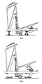
Figure 1 shows a lateral view of the mechanism in its operating configuration. -
Figure 2 shows a lateral view of the mechanism in its not operating configuration. -
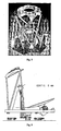
Figure 3 shows a lateral view of the mechanism inserted in an optical system of reflector antenna. -
Figure 4 shows a lateral view of the antenna itself. -
Figure 5 shows a prospect view of the retention and release system. -
Figure 6 shows prospect view of a structural and functional configuration of the mechanism of the invention in not operating condition with the retention and release system as closed. -
Figure 7 shows a prospect view of a structural and functional configuration of the mechanism of the invention in not operating condition, but with the retention and release system as opened. -
Figure 8 shows a prospect view of a structural and functional configuration of the mechanism of the invention in operating condition with the opened retention and release system and the system of multiple mechanical leverages. -
Figure 9 shows a lateral view of the reflector in nominal position, with a covering extension of nominal sizes. -
Figure 10 shows a lateral view of the reflector in backed position, with a covering extension of minimal sizes. -
Figure 11 shows a lateral view of the reflector in advanced position, with a covering extension of maximum sizes. -
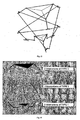
Figure 12 shows a scheme of the mechanism of the invention constituted by three terns of plane kinematisms which connect therebetween two triangular equilateral platforms, parallel therebetween. -
Figure 13 shows a prospect view of the scheme of the three terns of plane kinematisms. -
Figure 14 shows a prospect view of a single tern. -
Figure 15 shows a high view of a single tern. -
Figure 16 shows schemes of the three kinematisms. -
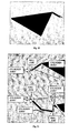
Figure 17 shows a prospect view of the kinematism ofTYPE 1. -
Figure 18 shows a prospect view of the kinematism ofTYPE 2. -
Figure 19 shows a prospect view of the articulated joint. -
Figure 20 shows a prospect view of the kinematism ofTYPE 3. -
Figure 21 shows the arrangement of the constraints. -
Figure 22 shows a prospect view of a Gregorian antenna. -
Figure 23 shows a lateral view of a Gregorian antenna having integrated the mechanism of the invention below the main reflector, without substantially modifying the mechanical design. - According to
Figure 1 , the mechanism in its operating configuration is constituted by a linear actuator (1), a system of multiple mechanical leverages or kinematisms (2), a retention and - release system (3), a supporting structure (4), an interface flange for the object to be moved (5), a device with controlled release (6).
- According to
Figure 2 , the mechanism in its not operating configuration shows the retention and release system (3) in closed condition, whereas the multiple mechanical leverages (2) appear retracted. - The retention and release system (3) is shown in
Figure 5 . It is mainly constituted by three upside-down V-like structures which connect at the top with the interface flange (5) by means of a device with controlled release (6) and arranged on three planes at 120 degrees therebetween. The V-like structures are connected to the supporting structure (4) by means of hinges or elastic joints (7) which allow the moving away thereof from the interface flange (4) after the device with controlled release (6) has been activated. - The mechanism when inserted into an optical system of reflector antenna allows implementing the translation of a reflecting surface as shown
Figure 3 , in the case of a reflector antenna of the "Dual Gregorian" type in not operating configuration, namely with the retention and release system (3) in closed condition and with retracted multiple mechanical leverages (2). - The same antenna is shown in
Figure 4 in operating condition with the retention and release system (3) in opened condition and with the multiple mechanical leverages (2) extended in the position thereof of maximum elongation. - A structural and functional configuration of the ZAM mechanism in not operating condition with the closed retention and release system is shown in
Figure 6 . - A structural and functional configuration of the ZAM mechanism in not operating condition, but with the opened retention and release system is shown in
Figure 7 . - A structural and functional configuration of the ZAM mechanism in operating condition and therefore with the opened retention and release system and the system of multiple mechanical leverages is shown in
Figure 8 . - Once the ZAM is in operating condition, substantially three operating modes of the antenna can be identified, which do not coincide with the ones of the mechanism, with no limits for intermediate positions which are omitted by way of simplicity.
- The reflector in nominal position; namely with a covering extension of nominal sizes, is shown in
Figure 9 . - The reflector in backed position, namely with a covering extension of minimal sizes, is shown
Figure 10 . - The reflector in advanced position, namely with a covering extension of maximum sizes, is shown in
Figure 11 . - The ZAM is constituted by three terns of plane kinematisms which connect two triangular equilateral parallel platforms one to the other, as shown in
Figure 12 and inFigure 13 . A single tern is represented inFigure 14 and Figure 15 and it is constituted by a kinematism ofTYPE 1, one ofTYPE 2 and one ofTYPE 3. - The kinematisms of
TYPE TYPE 2 lays on the plane π2, as shown inFigure 14 andFigure 16 . - Let's establish a system of inertial reference F 0 with axis z 0 orthogonal to the platforms and passing by the two centres of the same. The kinematisms appear with polar symmetry with respect to the vertical axis joining the centres of the two platforms.
- The Kinematism of
TYPE 1 ofFigure 17 constituted byLinks Figure 16 appears equal in three planes π1 belonging to the beam which has the axis z 0 as support and rotated by 120° therebetween.Links Figure 16 are constrained in fixed mutual position and are they hinged together in a fixed point in the space. In some cases, such as in the calculation of the degrees of freedom, they will be considered as a single body, designated Link 3-4, for convenience. - The Kinematism of
TYPE 2 ofFigure 18 is constituted by three pairs ofLinks 5 which lay in three planes π2 rotated by 30° with respect to the respective π1. Such planes form the side faces of a prism with triangular equilateral base the lower vertices thereof are the ends of the three Links 4 (shown inFigure 13 ), constrained to theLinks 5 by a suitable articulated joint. Such articulated joint, shown inFigure 19 , allows to eachLink 4 to operate a pair ofLinks 5 belonging to two different spiders. The kinematic property of the articulated joints lies in the fact of being connected to theLinks 4 by means of a ball joint and to theLinks 5 by means of cylindrical joints the axes thereof, orthogonal to the respective belonging planes of the Links, intersect in the centre of the ball joint, by preventing the creation of not balanced pairs. An equal three-dimensional articulated joint is fastened to the upper ends of theLinks 5 wherein theLinks 6 converge. - The Kinematism of
TYPE 3 ofFigure 20 is a simple mechanical leverage which transmits the motion to the upper platform: the contemporary action of the threeLinks 6 in the respective planes π1 obliges the platform to translate along the axis z 0. - The mechanism has been designed so as to show the only degree of translation freedom along the axis z, which translates into a relative motion between the platforms along the same axis. In order to have this kinematics, the arrangement of the constraints must be the one shown in
Figure 21 .
Claims (1)
- An actuation mechanism constituted by a linear actuator (1), a system of multiple mechanical leverages or kinematisms (2), a retention and release system (3), a supporting structure (4), an interface flange (5) for the object to be moved and a device with controlled release (6), wherein
the system of multiple mechanical leverages or kinematisms (2) at one end is connected to the interface flange (5) and at the other end is connected to the supporting structure (4);
the retention and release system (3) is constituted by three upside-down V-like structures which connect at the top with the interface flange (5) by means of the device with controlled release (6) arranged on three planes at 120 degrees therebetween, said V-like structures being connected to the supporting structure, (4) by means of hinges or elastic joints (7) which allow the moving away of said V-like structures from the interface flange (4) after the device with controlled release (6) has been activated.
Applications Claiming Priority (2)
| Application Number | Priority Date | Filing Date | Title |
|---|---|---|---|
| IT000337A ITRM20050337A1 (en) | 2005-06-28 | 2005-06-28 | MECHANISM OF IMPLEMENTATION WITH A THREE-DIMENSIONAL STRAIGHT GUIDE. |
| PCT/IT2006/000490 WO2007000789A1 (en) | 2005-06-28 | 2006-06-26 | Actuation mechanism with three-dimensional rectilinear guide |
Publications (2)
| Publication Number | Publication Date |
|---|---|
| EP1900058A1 EP1900058A1 (en) | 2008-03-19 |
| EP1900058B1 true EP1900058B1 (en) | 2011-04-13 |
Family
ID=37012115
Family Applications (1)
| Application Number | Title | Priority Date | Filing Date |
|---|---|---|---|
| EP06766359A Not-in-force EP1900058B1 (en) | 2005-06-28 | 2006-06-26 | Actuation mechanism with three-dimensional rectilinear guide |
Country Status (8)
| Country | Link |
|---|---|
| US (1) | US7623082B2 (en) |
| EP (1) | EP1900058B1 (en) |
| AT (1) | ATE505826T1 (en) |
| CA (1) | CA2613341C (en) |
| DE (1) | DE602006021307D1 (en) |
| ES (1) | ES2362114T3 (en) |
| IT (1) | ITRM20050337A1 (en) |
| WO (1) | WO2007000789A1 (en) |
Families Citing this family (5)
| Publication number | Priority date | Publication date | Assignee | Title |
|---|---|---|---|---|
| DE102008048951A1 (en) * | 2008-09-25 | 2010-04-08 | Puk-Werke Kg Kunststoff-Stahlverarbeitung Gmbh & Co | cableway |
| CN102384341B (en) * | 2010-08-31 | 2013-12-11 | 鸿富锦精密工业(深圳)有限公司 | Six-freedom degree motion platform |
| US9513168B2 (en) | 2014-09-23 | 2016-12-06 | Utah State University Research Foundation | Linear-motion stage |
| CN112730901B (en) * | 2020-12-07 | 2023-09-12 | 威凯检测技术有限公司 | Antenna bracket |
| CN119098937B (en) * | 2024-10-12 | 2025-10-17 | 北京航空航天大学 | Metamorphic operation platform based on plane symmetry Bricard mechanism |
Family Cites Families (6)
| Publication number | Priority date | Publication date | Assignee | Title |
|---|---|---|---|---|
| DE68920184T2 (en) * | 1988-04-08 | 1995-06-22 | Toshiba Kawasaki Kk | Portable antenna device. |
| US5485168A (en) * | 1994-12-21 | 1996-01-16 | Electrospace Systems, Inc. | Multiband satellite communication antenna system with retractable subreflector |
| DE19818240C2 (en) * | 1998-04-23 | 2000-06-29 | Daimler Chrysler Ag | Reflector and reflector element for antennas for use in space, and method for unfolding a reflector |
| US6559806B1 (en) * | 2000-12-29 | 2003-05-06 | Bellsouth Intellectual Property Corporation | Motorized antenna pointing device |
| US6466179B1 (en) * | 2001-03-20 | 2002-10-15 | Netune Communications, Inc. | Alignment jig assembly |
| US7411561B1 (en) * | 2005-04-27 | 2008-08-12 | The Boeing Company | Gimbaled dragonian antenna |
-
2005
- 2005-06-28 IT IT000337A patent/ITRM20050337A1/en unknown
-
2006
- 2006-06-26 WO PCT/IT2006/000490 patent/WO2007000789A1/en not_active Ceased
- 2006-06-26 DE DE602006021307T patent/DE602006021307D1/en active Active
- 2006-06-26 AT AT06766359T patent/ATE505826T1/en active
- 2006-06-26 CA CA2613341A patent/CA2613341C/en not_active Expired - Fee Related
- 2006-06-26 EP EP06766359A patent/EP1900058B1/en not_active Not-in-force
- 2006-06-26 ES ES06766359T patent/ES2362114T3/en active Active
- 2006-06-26 US US11/993,933 patent/US7623082B2/en not_active Expired - Fee Related
Also Published As
| Publication number | Publication date |
|---|---|
| CA2613341C (en) | 2014-05-20 |
| CA2613341A1 (en) | 2007-01-04 |
| US20080258987A1 (en) | 2008-10-23 |
| ITRM20050337A1 (en) | 2006-12-29 |
| DE602006021307D1 (en) | 2011-05-26 |
| ES2362114T3 (en) | 2011-06-28 |
| US7623082B2 (en) | 2009-11-24 |
| EP1900058A1 (en) | 2008-03-19 |
| WO2007000789A1 (en) | 2007-01-04 |
| ATE505826T1 (en) | 2011-04-15 |
Similar Documents
| Publication | Publication Date | Title |
|---|---|---|
| EP2825827B1 (en) | Mechanical support ring structure | |
| CN102102701B (en) | Device for the deployment and pointing of structure elements in a spatial environment | |
| US20140290419A1 (en) | Device for a body's spherical motion control | |
| EP0290729B1 (en) | Module for expandable truss structure and expandable truss structure employing said module | |
| US10195749B2 (en) | Hinge for use in a tension stiffened and tendon actuated manipulator | |
| US20210239196A1 (en) | Apparatus for Converting Motion | |
| EP2997201A2 (en) | Apparatus for converting motion and building assembly comprising the same | |
| US11981458B2 (en) | Separation system for a satellite | |
| US7623082B2 (en) | Actuation mechanism with three-dimensional rectilinear guide | |
| EP3186532A1 (en) | Apparatus for converting motion | |
| EP1783051A1 (en) | Combination actuator latch mechanism | |
| JP6952383B1 (en) | Lock mechanism and unmanned aerial vehicle equipped with it | |
| CN115871958B (en) | Space-deployable unit, plane-deployable antenna support truss and spacecraft | |
| US11713798B2 (en) | Apparatus for converting motion | |
| CN115626308A (en) | A Gravity Unloading System for Two-Stage Expanded Dual-Axis Tracking Spaceborne Antenna | |
| EP3869611B1 (en) | Articulated mechanism and articulated aiming system comprising the mechanism | |
| US8179598B1 (en) | Scanning wide field telescope (SWIFT) spaceflight-deployed payload | |
| JP6143644B2 (en) | Deployable structure and spacecraft equipped with the same | |
| EP4573297A1 (en) | Sliding pin-yoke mechanism | |
| US20210285527A1 (en) | Assembly for converting motion | |
| EP4632945A1 (en) | System and method for fine pointing of a payload | |
| US20260112810A1 (en) | Compact Stowing of an Antenna on a Space Vehicle using a Multi-Axis Boom | |
| CA3269298A1 (en) | System and method for fine pointing of a payload | |
| JPH08107305A (en) | Antenna reflector | |
| GB2579064A (en) | Apparatus for converting motion |
Legal Events
| Date | Code | Title | Description |
|---|---|---|---|
| PUAI | Public reference made under article 153(3) epc to a published international application that has entered the european phase |
Free format text: ORIGINAL CODE: 0009012 |
|
| 17P | Request for examination filed |
Effective date: 20080128 |
|
| AK | Designated contracting states |
Kind code of ref document: A1 Designated state(s): AT BE BG CH CY CZ DE DK EE ES FI FR GB GR HU IE IS IT LI LT LU LV MC NL PL PT RO SE SI SK TR |
|
| DAX | Request for extension of the european patent (deleted) | ||
| 17Q | First examination report despatched |
Effective date: 20080519 |
|
| DAX | Request for extension of the european patent (deleted) | ||
| GRAP | Despatch of communication of intention to grant a patent |
Free format text: ORIGINAL CODE: EPIDOSNIGR1 |
|
| GRAS | Grant fee paid |
Free format text: ORIGINAL CODE: EPIDOSNIGR3 |
|
| RAP1 | Party data changed (applicant data changed or rights of an application transferred) |
Owner name: FINMECCANICA - SOCIETA PER AZIONI |
|
| GRAA | (expected) grant |
Free format text: ORIGINAL CODE: 0009210 |
|
| AK | Designated contracting states |
Kind code of ref document: B1 Designated state(s): AT BE BG CH CY CZ DE DK EE ES FI FR GB GR HU IE IS IT LI LT LU LV MC NL PL PT RO SE SI SK TR |
|
| REG | Reference to a national code |
Ref country code: GB Ref legal event code: FG4D |
|
| REG | Reference to a national code |
Ref country code: CH Ref legal event code: EP |
|
| REG | Reference to a national code |
Ref country code: IE Ref legal event code: FG4D |
|
| REF | Corresponds to: |
Ref document number: 602006021307 Country of ref document: DE Date of ref document: 20110526 Kind code of ref document: P |
|
| REG | Reference to a national code |
Ref country code: DE Ref legal event code: R096 Ref document number: 602006021307 Country of ref document: DE Effective date: 20110526 |
|
| REG | Reference to a national code |
Ref country code: CH Ref legal event code: NV Representative=s name: GRIFFES CONSULTING SA |
|
| REG | Reference to a national code |
Ref country code: ES Ref legal event code: FG2A Ref document number: 2362114 Country of ref document: ES Kind code of ref document: T3 Effective date: 20110628 |
|
| REG | Reference to a national code |
Ref country code: NL Ref legal event code: VDEP Effective date: 20110413 |
|
| LTIE | Lt: invalidation of european patent or patent extension |
Effective date: 20110413 |
|
| PG25 | Lapsed in a contracting state [announced via postgrant information from national office to epo] |
Ref country code: PT Free format text: LAPSE BECAUSE OF FAILURE TO SUBMIT A TRANSLATION OF THE DESCRIPTION OR TO PAY THE FEE WITHIN THE PRESCRIBED TIME-LIMIT Effective date: 20110816 Ref country code: LT Free format text: LAPSE BECAUSE OF FAILURE TO SUBMIT A TRANSLATION OF THE DESCRIPTION OR TO PAY THE FEE WITHIN THE PRESCRIBED TIME-LIMIT Effective date: 20110413 Ref country code: SE Free format text: LAPSE BECAUSE OF FAILURE TO SUBMIT A TRANSLATION OF THE DESCRIPTION OR TO PAY THE FEE WITHIN THE PRESCRIBED TIME-LIMIT Effective date: 20110413 |
|
| PG25 | Lapsed in a contracting state [announced via postgrant information from national office to epo] |
Ref country code: BE Free format text: LAPSE BECAUSE OF FAILURE TO SUBMIT A TRANSLATION OF THE DESCRIPTION OR TO PAY THE FEE WITHIN THE PRESCRIBED TIME-LIMIT Effective date: 20110413 Ref country code: GR Free format text: LAPSE BECAUSE OF FAILURE TO SUBMIT A TRANSLATION OF THE DESCRIPTION OR TO PAY THE FEE WITHIN THE PRESCRIBED TIME-LIMIT Effective date: 20110714 Ref country code: LV Free format text: LAPSE BECAUSE OF FAILURE TO SUBMIT A TRANSLATION OF THE DESCRIPTION OR TO PAY THE FEE WITHIN THE PRESCRIBED TIME-LIMIT Effective date: 20110413 Ref country code: IS Free format text: LAPSE BECAUSE OF FAILURE TO SUBMIT A TRANSLATION OF THE DESCRIPTION OR TO PAY THE FEE WITHIN THE PRESCRIBED TIME-LIMIT Effective date: 20110813 Ref country code: SI Free format text: LAPSE BECAUSE OF FAILURE TO SUBMIT A TRANSLATION OF THE DESCRIPTION OR TO PAY THE FEE WITHIN THE PRESCRIBED TIME-LIMIT Effective date: 20110413 Ref country code: CY Free format text: LAPSE BECAUSE OF FAILURE TO SUBMIT A TRANSLATION OF THE DESCRIPTION OR TO PAY THE FEE WITHIN THE PRESCRIBED TIME-LIMIT Effective date: 20110413 Ref country code: FI Free format text: LAPSE BECAUSE OF FAILURE TO SUBMIT A TRANSLATION OF THE DESCRIPTION OR TO PAY THE FEE WITHIN THE PRESCRIBED TIME-LIMIT Effective date: 20110413 |
|
| PG25 | Lapsed in a contracting state [announced via postgrant information from national office to epo] |
Ref country code: NL Free format text: LAPSE BECAUSE OF FAILURE TO SUBMIT A TRANSLATION OF THE DESCRIPTION OR TO PAY THE FEE WITHIN THE PRESCRIBED TIME-LIMIT Effective date: 20110413 |
|
| PG25 | Lapsed in a contracting state [announced via postgrant information from national office to epo] |
Ref country code: EE Free format text: LAPSE BECAUSE OF FAILURE TO SUBMIT A TRANSLATION OF THE DESCRIPTION OR TO PAY THE FEE WITHIN THE PRESCRIBED TIME-LIMIT Effective date: 20110413 Ref country code: CZ Free format text: LAPSE BECAUSE OF FAILURE TO SUBMIT A TRANSLATION OF THE DESCRIPTION OR TO PAY THE FEE WITHIN THE PRESCRIBED TIME-LIMIT Effective date: 20110413 |
|
| PLBE | No opposition filed within time limit |
Free format text: ORIGINAL CODE: 0009261 |
|
| STAA | Information on the status of an ep patent application or granted ep patent |
Free format text: STATUS: NO OPPOSITION FILED WITHIN TIME LIMIT |
|
| PG25 | Lapsed in a contracting state [announced via postgrant information from national office to epo] |
Ref country code: RO Free format text: LAPSE BECAUSE OF FAILURE TO SUBMIT A TRANSLATION OF THE DESCRIPTION OR TO PAY THE FEE WITHIN THE PRESCRIBED TIME-LIMIT Effective date: 20110413 Ref country code: SK Free format text: LAPSE BECAUSE OF FAILURE TO SUBMIT A TRANSLATION OF THE DESCRIPTION OR TO PAY THE FEE WITHIN THE PRESCRIBED TIME-LIMIT Effective date: 20110413 Ref country code: DK Free format text: LAPSE BECAUSE OF FAILURE TO SUBMIT A TRANSLATION OF THE DESCRIPTION OR TO PAY THE FEE WITHIN THE PRESCRIBED TIME-LIMIT Effective date: 20110413 Ref country code: PL Free format text: LAPSE BECAUSE OF FAILURE TO SUBMIT A TRANSLATION OF THE DESCRIPTION OR TO PAY THE FEE WITHIN THE PRESCRIBED TIME-LIMIT Effective date: 20110413 |
|
| 26N | No opposition filed |
Effective date: 20120116 |
|
| REG | Reference to a national code |
Ref country code: IE Ref legal event code: MM4A |
|
| PG25 | Lapsed in a contracting state [announced via postgrant information from national office to epo] |
Ref country code: IE Free format text: LAPSE BECAUSE OF NON-PAYMENT OF DUE FEES Effective date: 20110626 |
|
| REG | Reference to a national code |
Ref country code: DE Ref legal event code: R097 Ref document number: 602006021307 Country of ref document: DE Effective date: 20120116 |
|
| PG25 | Lapsed in a contracting state [announced via postgrant information from national office to epo] |
Ref country code: MC Free format text: LAPSE BECAUSE OF NON-PAYMENT OF DUE FEES Effective date: 20110630 |
|
| PG25 | Lapsed in a contracting state [announced via postgrant information from national office to epo] |
Ref country code: LU Free format text: LAPSE BECAUSE OF NON-PAYMENT OF DUE FEES Effective date: 20110626 |
|
| PG25 | Lapsed in a contracting state [announced via postgrant information from national office to epo] |
Ref country code: BG Free format text: LAPSE BECAUSE OF FAILURE TO SUBMIT A TRANSLATION OF THE DESCRIPTION OR TO PAY THE FEE WITHIN THE PRESCRIBED TIME-LIMIT Effective date: 20110713 |
|
| PG25 | Lapsed in a contracting state [announced via postgrant information from national office to epo] |
Ref country code: TR Free format text: LAPSE BECAUSE OF FAILURE TO SUBMIT A TRANSLATION OF THE DESCRIPTION OR TO PAY THE FEE WITHIN THE PRESCRIBED TIME-LIMIT Effective date: 20110413 |
|
| PG25 | Lapsed in a contracting state [announced via postgrant information from national office to epo] |
Ref country code: HU Free format text: LAPSE BECAUSE OF FAILURE TO SUBMIT A TRANSLATION OF THE DESCRIPTION OR TO PAY THE FEE WITHIN THE PRESCRIBED TIME-LIMIT Effective date: 20110413 |
|
| REG | Reference to a national code |
Ref country code: FR Ref legal event code: PLFP Year of fee payment: 10 |
|
| REG | Reference to a national code |
Ref country code: FR Ref legal event code: PLFP Year of fee payment: 11 |
|
| REG | Reference to a national code |
Ref country code: FR Ref legal event code: PLFP Year of fee payment: 12 |
|
| PGFP | Annual fee paid to national office [announced via postgrant information from national office to epo] |
Ref country code: FR Payment date: 20170621 Year of fee payment: 12 Ref country code: GB Payment date: 20170620 Year of fee payment: 12 Ref country code: DE Payment date: 20170621 Year of fee payment: 12 Ref country code: CH Payment date: 20170620 Year of fee payment: 12 |
|
| PGFP | Annual fee paid to national office [announced via postgrant information from national office to epo] |
Ref country code: IT Payment date: 20170529 Year of fee payment: 12 Ref country code: AT Payment date: 20170622 Year of fee payment: 12 |
|
| PGFP | Annual fee paid to national office [announced via postgrant information from national office to epo] |
Ref country code: ES Payment date: 20170725 Year of fee payment: 12 |
|
| REG | Reference to a national code |
Ref country code: DE Ref legal event code: R119 Ref document number: 602006021307 Country of ref document: DE |
|
| REG | Reference to a national code |
Ref country code: CH Ref legal event code: PL |
|
| REG | Reference to a national code |
Ref country code: AT Ref legal event code: MM01 Ref document number: 505826 Country of ref document: AT Kind code of ref document: T Effective date: 20180626 |
|
| GBPC | Gb: european patent ceased through non-payment of renewal fee |
Effective date: 20180626 |
|
| PG25 | Lapsed in a contracting state [announced via postgrant information from national office to epo] |
Ref country code: AT Free format text: LAPSE BECAUSE OF NON-PAYMENT OF DUE FEES Effective date: 20180626 Ref country code: LI Free format text: LAPSE BECAUSE OF NON-PAYMENT OF DUE FEES Effective date: 20180630 Ref country code: CH Free format text: LAPSE BECAUSE OF NON-PAYMENT OF DUE FEES Effective date: 20180630 Ref country code: DE Free format text: LAPSE BECAUSE OF NON-PAYMENT OF DUE FEES Effective date: 20190101 Ref country code: IT Free format text: LAPSE BECAUSE OF NON-PAYMENT OF DUE FEES Effective date: 20180626 Ref country code: GB Free format text: LAPSE BECAUSE OF NON-PAYMENT OF DUE FEES Effective date: 20180626 Ref country code: FR Free format text: LAPSE BECAUSE OF NON-PAYMENT OF DUE FEES Effective date: 20180630 |
|
| REG | Reference to a national code |
Ref country code: ES Ref legal event code: FD2A Effective date: 20190916 |
|
| PG25 | Lapsed in a contracting state [announced via postgrant information from national office to epo] |
Ref country code: ES Free format text: LAPSE BECAUSE OF NON-PAYMENT OF DUE FEES Effective date: 20180627 |