EP1898575A2 - Microwave wireless communication system - Google Patents
Microwave wireless communication system Download PDFInfo
- Publication number
- EP1898575A2 EP1898575A2 EP20070253503 EP07253503A EP1898575A2 EP 1898575 A2 EP1898575 A2 EP 1898575A2 EP 20070253503 EP20070253503 EP 20070253503 EP 07253503 A EP07253503 A EP 07253503A EP 1898575 A2 EP1898575 A2 EP 1898575A2
- Authority
- EP
- European Patent Office
- Prior art keywords
- communication
- microwave
- set value
- equipment
- modification
- Prior art date
- Legal status (The legal status is an assumption and is not a legal conclusion. Google has not performed a legal analysis and makes no representation as to the accuracy of the status listed.)
- Granted
Links
Images




Classifications
-
- H—ELECTRICITY
- H04—ELECTRIC COMMUNICATION TECHNIQUE
- H04W—WIRELESS COMMUNICATION NETWORKS
- H04W24/00—Supervisory, monitoring or testing arrangements
- H04W24/02—Arrangements for optimising operational condition
Definitions
- the present invention relates to a microwave wireless communication system, and more particularly to a microwave wireless communication system, a microwave communication network monitoring equipment, a microwave communication equipment, a network monitoring program, and a control program, which allow upgrading a microwave wireless communication equipment of a predetermined section of a microwave communication network.
- Microwave wireless communication systems so far developed include the one disclosed in Japanese Laid-open patent publication NO. 2005-347982 .
- the wireless communication system according to this document is capable of efficiently monitoring and controlling, by a top master station, a plurality of microwave wireless communication equipments provided thereunder.
- a monitor and control equipment that monitors and controls the respective wireless equipments is connected to the master station, to thereby monitor and control the plurality of microwave wireless communication equipments provided under the master station.
- step S301 when the conventional microwave wireless communication system is to be upgraded, firstly an upgrade request from a customer is accepted (step S301), and a theoretical calculation is performed to estimate the transmission quality to be attained after the upgrading (step S303). Then actual detail of modification of the system is decided, according to the calculation result (step S305). According to the decision, the upgraded equipment is substituted (step S307). Then the system is activated, to thereby collect monitored data and measure the transmission quality (step S309). The measurement result is then analyzed (step S311), and if the result proves unsatisfactory the process returns to the step S303 so as to repeat the steps S303 to S309, until the expected transmission quality is attained. If the analysis result proves satisfactory, the upgrading is completed (step S313).
- the transmission quality after the upgrading can only be estimated through the theoretical calculation, and besides the substitution of the system has to be practically performed based on the estimation result. Accordingly, in case an unexpected factor proves to be present on the actual line, the transmission quality often fails to satisfy the specification designated by the customer. Consequently, the transmission quality still has to be measured after actually substituting the system, and the system modification has be to repeatedly executed until the result satisfies the customer's specification.
- An exemplary object of the invention is to provide a microwave wireless communication system that allows securing an adequate transmission quality with precision, when the system is to be upgraded.
- a microwave wireless communication system including a plurality of microwave communication equipments linked at an end via wire communication and at the other end via microwave wireless communication; and a network monitoring equipment that monitors and controls a microwave communication network including the plurality of microwave communication equipments; wherein the network monitoring equipment includes an acceptance unit that accepts, when a microwave communication equipment of a predetermined section is to be upgraded, modification of a set value for communication control for the microwave communication equipment; an update unit that upgrades the microwave communication equipment according to the modification of the set value for communication control accepted by the acceptance unit; a measurement unit that measures transmission quality of the microwave communication network of said microwave communication equipment that has been upgraded; and a presentation unit that presents the transmission quality measured by the measurement unit.
- the transmission quality herein referred to may be measured based on various data, such as a received field characteristic value of each microwave communication equipment or a waveform of the transmitted or received wave.
- the microwave wireless communication system thus configured allows tentatively modifying the set value of the microwave communication equipment of a certain section and thereby measuring the transmission quality of the network and checking the result.
- the system therefore, enables estimating in advance degradation of the transmission quality originating from the modification of the set value, for example the transmission capacity and the modulation system, and thus performing appropriate system modification based on the estimation.
- the set values may be further modified according to the presented result, so that the system may be modified to a higher level.
- the microwave communication equipment may include a wire communication interface unit that makes wire communication with first another microwave communication equipment in the microwave communication network, a wireless communication unit that makes microwave wireless communication with second another microwave communication equipment in the microwave communication network, a set value storage unit that stores therein a variable set value for communication control, a modification acceptance unit that accepts a modification instruction of the set value for communication control from the network monitoring equipment, a modification unit that modifies the set value for communication control in the set value storage unit according to the modification instruction, and a control unit that controls communication according to the set value for communication control in the set value storage unit.
- the network monitoring equipment may further include a first restoration instruction acceptance unit that accepts an instruction to restore the set value for communication control before the modification, and a restoration instruction unit that instructs, once the restoration instruction is accepted, the microwave communication equipment to restore the set value for communication control to the value before the modification, and the microwave communication equipment may further include a backup unit that backs up the set value for communication control in the set value storage unit when the modification acceptance unit accepts the modification instruction, a second restoration instruction acceptance unit that accepts the restoration instruction from the network monitoring equipment, and a restoration unit that restores the set value for communication control backed up by the backup unit in the set value storage unit, when the second restoration instruction acceptance unit accepts the restoration instruction.
- Such configuration allows restoring the set value, in case where the transmission quality proves to exceed a permissible range after the tentative modification, to the value before the modification, thereby restoring the original transmission quality.
- work efficiency for upgrading can be improved without the need to replace the hardware such as an antenna, and the cost of such unnecessary hardware can be saved.
- the set value for communication control may include at least one of set value of a transmission capacity and a type of modulation system.
- the microwave wireless communication system may further include a history accumulation unit that causes the measurement unit of the network monitoring equipment to measure the transmission quality for a predetermined period, and accumulates therein a history of the transmission quality that has been measured, and the presentation unit may further present the history.
- Such configuration allows checking the transmission quality of the predetermined period, thereby enabling checking the transmission quality reflecting fluctuation in environment, such as weather or radiowave condition, which leads to higher reliability of the system.
- a microwave communication network monitoring equipment that monitors and controls a microwave communication network including a plurality of microwave communication equipments linked at an end via wire communication and at the other end via microwave wireless communication, including:
- a microwave communication equipment that forms a microwave communication network, including:
- a microwave communication network monitoring program that monitors and controls a microwave wireless communication network including a plurality of microwave communication equipments linked at an end via wire communication and at the other end via microwave wireless communication, causing a computer to execute functions including:
- a control program that controls a microwave communication equipment forming a microwave communication network, causing a computer that includes a set value storage unit that stores therein a variable set value for communication control for the microwave communication equipment to execute functions including:
- the present invention provides a microwave wireless communication system that allows securing an adequate transmission quality with precision, when the microwave communication network is to be upgraded.
- Fig. 1 is a block diagram showing a network configuration of a microwave wireless communication system according to the exemplary embodiment of the present invention.
- the microwave wireless communication system according to the exemplary embodiment includes a plurality of microwave communication equipments 10, mutually linked via microwave wireless communication to form a microwave communication network 1.
- the system also includes a network monitoring equipment 30 that monitors and controls the microwave communication network 1, to thereby tentatively modify a set value for communication control for the microwave communication equipment 10 of a predetermined section in the microwave communication network 1 and monitors the transmission performance, when necessary during an upgrading process of the microwave communication network 1.
- Each microwave communication equipment 10 is provided with an antenna 12, so as to perform wireless communication with the antenna 12 of the other opposing microwave communication equipment 10.
- the microwave communication equipments 10 are serially connected in Fig. 1, another network may be branched from one of the microwave communication equipments 10. Also, in the subsequent drawings, structure of such portions that are not involved with the essence of the present invention is not shown.
- the microwave wireless communication system includes the plurality of microwave communication equipments 10 linked at an end via wire communication and at the other end via microwave wireless communication, and the network monitoring equipment 30 that monitors and controls the microwave communication network 1 including the plurality of microwave communication equipments, and the network monitoring equipment 30 accepts, when the microwave communication equipment 10 of the predetermined section is to be upgraded, modification of the set value for communication control for the microwave communication equipment 10; upgrades the microwave communication equipment 10 according to the accepted modification of the set value for communication control; measures transmission quality of the upgraded microwave communication network 1; and presents the measured transmission quality.
- the microwave wireless communication system includes the network monitoring equipment (abbreviated as NMS in the drawings) 30 and a terminal device 40.
- the network monitoring equipment 30 is for example a personal computer, and includes an operation unit 32 that accepts manipulation by an operator 5, a monitor 34 that displays a screen, and a printer 36 that prints.
- the network monitoring equipment 30 is connected, for example, to the microwave communication equipment 10 marked as No.1 in the microwave communication network 1, to thereby monitor and control the microwave communication equipments 10 in the microwave communication network 1, as well as to execute a program and modification of set value.
- the microwave communication equipment 10 and the network monitoring equipment 30 may be connected, for example, via a USB(Universal Serial Bus) cable.
- Examples of the operation unit 32 include a keyboard, a mouse, a tablet, an operating button, and a touch panel.
- Examples of the monitor 34 include a light, an LED(Light-Emitting Diode), a CRT(Cathode-Ray Tube) monitor, and an LCD(Liquid Crystal Display).
- the terminal device 40 is connected to one of the microwave communication equipments 10 in the microwave communication network 1, to thereby monitor and modify the set value of the connected microwave communication equipment 10.
- the microwave communication equipment 10 and the terminal device 40 may be connected, for example, via a USB cable.
- the terminal device 40 is for example a personal computer, details of which are not specifically limited, and is connectible to any of the microwave communication equipment 10 in the microwave communication network 1 via a USB cable or the like.
- the terminal device 40 may monitor and modify the set value for the connected microwave communication equipment 10 in the microwave communication network 1.
- the respective constituents of the microwave communication equipment 10 and the network monitoring equipment 30, which are shown in Figs. 2 and 3, may be materialized by a desired combination of hardware and software, such as a CPU(Central Processing Unit) or memory of a given computer, a program installed in the memory so as to execute the function of the constituents shown therein, a storage unit such as a hard disk that stores such program, and a network connection interface.
- a desired combination of hardware and software such as a CPU(Central Processing Unit) or memory of a given computer, a program installed in the memory so as to execute the function of the constituents shown therein, a storage unit such as a hard disk that stores such program, and a network connection interface.
- Fig. 2 is a functional block diagram showing a configuration of the microwave communication equipment 10.
- the microwave communication equipment 10 includes a wire communication interface unit (communication interface unit 102) that performs wire communication with first another microwave communication equipment 10 in the microwave communication network 1, a wireless communication unit (wireless communication control unit 108 and antenna 12) that performs microwave wireless communication with second another microwave communication equipment 10 in the microwave communication network 1, a set value storage unit (storage unit 112) that stores therein the variable set value for communication control, a modification acceptance unit (NMS interface unit 114 and control unit 110) that accepts a modification instruction of the set value for communication control from the network monitoring equipment 30, a modification unit 120 that modifies the set value for communication control in the set value storage unit (storage unit 112) according to the modification instruction, and a control unit (control unit 110, data processing unit 104, modem 106, and wireless communication control unit 108) that controls the communication according to the set value for communication control in the set value storage unit (storage unit 112).
- a wire communication interface unit communication interface unit 102
- the microwave communication equipment 10 may further include a backup unit (modification unit 120) that backs up the set value for communication control in the set value storage unit (storage unit 112) when the modification acceptance unit (NMS interface unit 114 and control unit 110) accepts the modification instruction, a second restoration instruction acceptance unit (NMS interface unit 114 and control unit 110) that accepts a restoration instruction from the network monitoring equipment 30, and a restoration unit (modification unit 120) that restores the set value for communication control backed up by the backup unit in the set value storage unit, when the second restoration instruction acceptance unit accepts the restoration instruction.
- a backup unit modification unit 120
- modification unit 120 backs up the set value for communication control in the set value storage unit (storage unit 112) when the modification acceptance unit (NMS interface unit 114 and control unit 110) accepts the modification instruction
- NPS interface unit 114 and control unit 110 receives a restoration instruction from the network monitoring equipment 30
- a restoration unit restores the set value for communication control backed up by the backup unit in the set value storage unit
- the microwave communication equipment 10 may include a microcomputer, and may be realized by causing a CPU to execute a control program stored in a ROM(Read Only Memory) or the like.
- the control program of the microwave communication equipment 10 according to the exemplary embodiment may be set up so as to cause a computer including the set value storage unit (storage unit 112) that stores therein the variable set value for communication control for the microwave communication equipment 10 to perform the function of: controlling wire communication with first another microwave communication equipment 10 in the microwave communication network 1 (control unit 110 and communication interface unit 102); controlling microwave wireless communication with second another microwave communication equipment 10 in the microwave communication network 1 (control unit 110 and wireless communication control unit 108); accepting a modification instruction of the set value for communication control (NMS interface unit 114 and control unit 110); modifying the set value for communication control in the set value storage unit according to the modification instruction (modification unit 120); and controlling the communication according the set value for communication control in the set value storage unit (storage unit 112) (control unit 110, data processing unit 104, modem 106, and
- the microwave communication equipment 10 includes the communication interface unit (communication I/F) 102, the data processing unit 104, the modem 106, the wireless communication control unit 108, the control unit 110, the storage unit 112, the NMS interface unit (NMS I/F) 114, a terminal interface unit (terminal I/F) 116, and the modification unit 120.
- communication I/F communication interface unit
- NMS I/F NMS interface unit
- terminal I/F terminal interface unit
- the communication interface unit 102 serves for mutual connection of one of the microwave communication equipments 10 with another opposing microwave communication equipment 10, such as the microwave communication equipment 10 marked as No.2 and the one marked as No.3 in Fig. 1, to thereby make communication.
- the communication interface unit 102 may be a PDH (Pre synchronous Digital Hierarchy) interface, a SDH (Synchronous Digital Hierarchy) interface, or a LAN(Local Area Network) interface, for example.
- Signals to be communicated between the communication interface units 102 of the opposing microwave communication equipments 10 may include a main signal and an auxiliary signal.
- the data processing unit 104 processes a signal communicated with another microwave communication equipment 10 via the communication interface unit 102, and delivers the processed signal to the modem 106 and the control unit 110.
- the data processing unit 104 may be materialized by a digital processor unit (DPU) or the like, and modifies the transmission rate according to the number of inputs/outputs through the communication interface unit 102.
- DPU digital processor unit
- the modem 106 modulates a signal input by the data processing unit 104, and delivers the modulated signal to the wireless communication control unit 108, and also demodulates a signal input by the wireless communication control unit 108, and delivers the demodulated signal to the data processing unit 104.
- the modulation system may be controlled and modified by the control unit 110, according to an instruction from the network monitoring equipment 30, which will be referred to later. Examples of the modulation system include, for example, 4PSK, 16QAM, 32QAM, and 128QAM.
- the wireless communication control unit 108 performs microwave wireless communication with another microwave communication equipment 10 via the antenna 12.
- the control unit 110 controls each element of the microwave communication equipment 10, as well as the entirety thereof.
- the storage unit 112 stores therein the set value for communication control, and the control program that controls the microwave communication equipment 10.
- the control unit 110 executes the control program stored in the storage unit 112, thereby controlling the entire equipment.
- the control unit 110 further controls the action of the data processing unit 104, the modem 106, and the wireless communication control unit 108 according to the set value for communication control, thereby controlling the communication.
- the control program and the set value for communication control stored in the storage unit 112 may be downloaded from the network monitoring equipment 30 for example, via the NMS interface unit 114, so as to upgrade the control program, or update or set the set value for communication control.
- the NMS interface unit 114 makes communication with the network monitoring equipment 30. Examples of the NMS interface unit 114 include a USB or a LAN.
- the terminal interface unit 116 makes communication with the terminal device 40.
- the microwave communication equipment 10 includes both of the NMS interface unit 114 and the terminal interface unit 116 in the exemplary embodiment, the present invention is not limited to such structure.
- the microwave communication equipment 10 may solely include the NMS interface unit 114, such that the NMS interface unit 114 is also connected to the terminal device 40.
- the modification unit 120 receives via the control unit 110 the set value for communication control set by the network monitoring equipment 30, to be described later, through the NMS interface unit 114 or the communication interface unit 102, and modifies the set value for communication control stored in the storage unit 112 to the received value. Also, the modification unit 120 may update the control program stored in the storage unit 112 based on the upgraded version of the control program downloaded from the network monitoring equipment 30. The modification unit 120 also takes, when modifying the set value for communication control, the backup of the original set value for communication control, so as to restore the modified set value for communication control to the backed-up value, when requested by the network monitoring equipment 30.
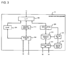
- Fig. 3 is a functional block diagram showing a configuration of the network monitoring equipment 30 according to the exemplary embodiment.
- the network monitoring equipment 30 according to the exemplary embodiment includes an acceptance unit 208 that accepts, when upgrading the microwave communication equipment 10 of a predetermined section, the modification of the set value for communication control for the relevant microwave communication equipment 10, an update unit (equipment control unit 210) that upgrades the microwave communication equipment 10 according to the modification of the set value for communication control accepted by the acceptance unit 208, a measurement unit (data collection unit 220 and analysis unit 224) that measures transmission quality of the upgraded microwave communication network 1 of the microwave communication equipment 10, and a presentation unit (display control unit 228 and monitor 34) that presents the transmission quality measured by the measurement unit.
- an acceptance unit 208 that accepts, when upgrading the microwave communication equipment 10 of a predetermined section, the modification of the set value for communication control for the relevant microwave communication equipment 10
- an update unit equipment control unit 210) that upgrades the microwave communication equipment 10 according to the modification of the set value for communication control accepted by the acceptance unit 208
- the network monitoring equipment 30 may further include a first restoration instruction acceptance unit (acceptance unit 208) that accepts an instruction to restore the set value for communication control before the modification, and a restoration instruction unit (equipment control unit 210) that instructs the microwave communication equipment 10, once the restoration instruction is accepted, to restore the set value for communication control to the value before the modification.
- a first restoration instruction acceptance unit acceptance unit 208
- a restoration instruction unit equipment control unit 210) that instructs the microwave communication equipment 10, once the restoration instruction is accepted, to restore the set value for communication control to the value before the modification.
- the network monitoring equipment 30 may be realized by executing the network monitoring program installed in the computer.
- the network monitoring program according to the exemplary embodiment serves to monitor and control a microwave wireless communication network 1 including a plurality of microwave communication equipments 10 linked at an end via wire communication and at the other end via microwave wireless communication, by causing the computer (network monitoring equipment 30) to perform function of:
- the network monitoring equipment 30 includes an interface unit (I/F) 202, a download (DL) unit 204, the acceptance unit 208, the equipment control unit 210, the data collection unit 220, a monitored data storage unit (marked as “monitored data” in Fig. 3) 222, the analysis unit 224, an analysis result storage unit (marked as "analysis result” in Fig. 3) 226, and the display control unit 228.
- I/F interface unit
- DL download
- the interface unit 202 executes communication with the microwave communication equipment 10.
- the network monitoring equipment 30 and the microwave communication equipment 10 may be connected, for example, via a USB cable.
- the download unit 204 downloads, from the microwave communication equipment 10 via the interface unit 202, a setting screen used for setting the variable set value for communication control for the microwave communication equipment 10. More specifically, the operator 5 requests the upgrading of the microwave communication equipment 10 of a predetermined section, by manipulating the operation unit 32. The designation of the predetermined section is accepted by the acceptance unit 208 to be described later, so that the acceptance unit 208 notifies the download unit 204 of the designation. The download unit 204 downloads, upon accepting the upgrading request, the setting screen from the microwave communication equipment 10 of the predetermined section via the interface unit 202, and displays the setting screen on the monitor 34.
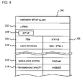
- FIG. 4 depicts an example of the setting screen.
- An hardware setup screen 300 includes a setting listing 302 and a set button (marked as "set up” in Fig. 4) 304.
- the setting listing 302 contains statuses 308 corresponding to a plurality of items 306, and the screen turns into a modification screen (not shown) of the status 308 with respect to each of the items 306, upon selection by the operator 5 by, for example, double-clicking the set button 304 via the operation unit 32.
- the items 306 may include, for example, a user interface 310, a modulation system 312, and a transmission capacity 314.
- Fig. 4 shows a sample screen in which "SDH STM-1" is selected as the user interface 310, "128QAM” system as the modulation system 312, and "156 (MB)" as the transmission capacity 314.
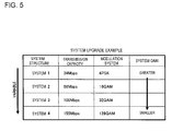
- upgrade herein means, as shown in Fig. 5, modifying the specification of a system 1 to that of a system 2, system 3, or to a system 4, for example increasing the transmission capacity and modifying the modulation system.
- the acceptance unit 208 accepts designation of which section corresponding to the microwave communication equipment 10 to be modified, among the plurality of microwave communication equipments 10 forming the microwave communication network 1. To be more detailed, the acceptance unit 208 accepts the section designated by the operator 5 via manipulation of the operation unit 32, and delivers the designation to the download unit 204 and the equipment control unit 210. The acceptance unit 208 further accepts various set values designated in the setting screen downloaded by the download unit 204 and displayed on the monitor 34. As described above, the acceptance unit 208 may accept the designation of, for example, the user interface 310, the modulation system 312, and the transmission capacity 314. The acceptance unit 208 also accepts from the operator 5 the restoration instruction of the backed-up set value for the microwave communication equipment 10, and notifies the equipment control unit 210 of the restoration instruction.
- the equipment control unit 210 controls, via the interface unit 202, the relevant microwave communication equipment 10 of the section in the microwave communication network 1 accepted by the acceptance unit 208, so as to modify the set value accepted by the acceptance unit 208.
- the equipment control unit 210 also controls the microwave communication equipment 10 so as to restore the backed-up set value, accepted by the acceptance unit 208.
- the microwave communication equipment 10 restores the original set value backed up when the set value was modified, in response to the restoration instruction from the network monitoring equipment 30.
- the data collection unit 220 collects data for monitoring the microwave communication equipment 10, via the interface unit 202.
- a data format received from the microwave communication equipment 10 may be configured such that a main signal (payload) corresponds to a designated transmission rate (number of inputs and outputs), and auxiliary signals follow.
- the auxiliary signals may include, for example, an error correction signal and an additional control signal used for the control between the microwave communication equipment 10 and the network monitoring equipment 30.
- the additional control signal may indicate which of the microwave communication equipments 10 is to be controlled, which of the set values is to be modified, and the modified set value itself.
- the monitored data storage unit 222 stores therein the monitored data collected by the data collection unit 220. Items to be monitored include, for example, a signal error, hardware malfunction, received field, transmission power, various setting information such as frequency, transmission capacity, and modulation system.
- the monitored data storage unit 222 also stores a history of the monitored data collected by the data collection unit 220 in a predetermined period.
- the analysis unit 224 analyzes the transmission quality based on the monitored data stored in the monitored data storage unit 222.
- the analysis result storage unit 226 stores therein the analysis result provided by the analysis unit 224.
- the display control unit 228 accepts an instruction of the operator 5 via the operation unit 32, to thereby cause the monitor 34 to display a screen showing the designated analysis result.
- the display control unit 228 displays a screen showing the analysis result, based on the data stored in the monitored data storage unit 222 and the analysis result storage unit 226.
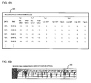
- the display control unit 228 may display a received field characteristic log screen 320 shown in Fig. 6A.
- the received field characteristic log screen 320 contains a listing showing a history of the received field characteristic of each of the microwave communication equipments 10 No.1 and No.2 of the designated section, collected every second.
- Fig. 6B which represents a received field characteristic graph screen 330.
- the received field characteristic graph screen 330 indicates the history of the received field characteristic log screen 320 in a graph format, with the horizontal axis representing the elapsed time.
- FIG. 7 is a flowchart showing an example of the upgrading process of the microwave wireless communication system according to the exemplary embodiment, and of the operation of the respective equipments during the process. Figs. 1 through 7 will be referred to for the description.
- the operator 5 starts to upgrade the microwave communication equipment 10 of a predetermined section in the microwave communication network 1, through the network monitoring equipment 30 (step S11).
- the operator 5 manipulates the operation unit 32 of the network monitoring equipment 30, to thereby designate the section to be upgraded (step S13).
- the acceptance unit 208 accepts the section designated by the operator 5 (step S101).
- the download unit 204 applies for downloading the hardware setup screen 300, to the microwave communication equipment 10 of the predetermined section (step S103), so that the microwave communication equipment 10 uploads the hardware setup screen 300, in compliance with the request from the network monitoring equipment 30 (step S201).
- the hardware setup screen 300 shown in Fig. 4 is displayed on the monitor 34 (step S105).
- the operator 5 then presses the set button 304 on the hardware setup screen 300 so as to turn the screen into the setting screen, and inputs the set value via the operation unit 32 (step S15).
- the acceptance unit 208 accepts the set value thus input (step S107).
- the equipment control unit 210 controls, via the interface unit 202, the microwave communication equipment 10 of the section accepted by the acceptance unit 208 so as to modify the set value accepted by the acceptance unit 208 (step S109).
- the additional data control signal may carry the modification instruction of the set value.
- the microwave communication equipment 10 backs up, once the control unit 110 receives the set value modification instruction from the network monitoring equipment 30 via the NMS interface unit 114, the original set value initially stored in the storage unit 112 (step S203).
- a purpose of taking the backup is to restore the original set value in case of need, depending on the analysis result upon analyzing the transmission quality based on the tentatively modified set value.
- the control unit 110 updates the set value stored in the storage unit 112, to the new set value received via the terminal interface unit 116 (step S205).
- the setting as the system 1 shown in Fig. 5 for the microwave communication equipment 10 is to be upgraded to the setting as the system 2. More specifically, the transmission capacity is to be modified from 34 Mbps to 68 Mbps, and the modulation system from 4PSK to 16QAM.
- the control unit 110 then starts to control the modem 106 based on the updated setting stored in the storage unit 112, i.e. the transmission capacity of 68 Mbps and the modulation system of 16QAM, thereby starting the communication with the relevant microwave communication equipment 10 via the wireless communication control unit 108 (step S207).
- the data collection unit 220 starts collecting the monitored data so as to monitor the transmission quality, in the network monitoring equipment 30 (step S111).
- the monitored data collected by the data collection unit 220 is sequentially stored in the monitored data storage unit 222, and accumulated therein (step S113).
- the analysis unit 224 analyzes the transmission quality based on the monitored data accumulated in the monitored data storage unit 222 (step S115).
- the analysis result is stored in the analysis result storage unit 226.
- the display control unit 228 causes the monitor 34 to display the history information accumulated in the monitored data storage unit 222 and the analysis result stored in the analysis result storage unit 226, for example in the form of the received field characteristic log screen 320 shown in Fig. 6A (step S117).
- the history information and the analysis result may also be printed out by the printer 36.
- the operator 5 checks whether the transmission quality satisfies a predetermined quality, based on the analysis result and the history information displayed (step S17). It is now assumed that the upgrading is addition of space diversity for example. As shown in Fig. 8A, in the case where the received field characteristic (RSL) is lowered at different positions between the main system and the space diversity (SD) system, the main system and the SD system can be construed as being mutually complementary, and hence under a desirable state. On the other hand, in the case where the RSL is lowered at the same position in both of the main system and the SD system as shown in Fig. 8B, it is concluded that the state is undesirable.
- RSS received field characteristic
- SD space diversity
- the process is completed. If the transmission quality is undesirable (NO at step S19), the operator 5 decides whether there is a need for modification of the set value or not(step S21), and if the modification is to be made (YES at step S21), the process returns to the step S13, so that the network monitoring equipment 30 enters a standby state pending the section designation by the operator 5.
- the operator 5 may judge the transmission quality and input the result via the operation unit 32.
- the analysis unit 224 may compare the quality data with a predetermined threshold value to thereby decide whether the transmission quality is within the permissible range, and display the result on the monitor 34.
- the operator 5 issues the restoration instruction of the backed-up set value via the operation unit 32 (step S23), so that the acceptance unit 208 in the network monitoring equipment 30 accepts the restoration instruction, and the equipment control unit 210 gives the restoration instruction of the set value to the relevant microwave communication equipment 10 via the interface unit 202 (step S119).
- the control unit 110 accepts the restoration instruction via the NMS interface unit 114, and makes the modification unit 120 restore the set value in the storage unit 112 (step S209).
- the history of the measurement result of the transmission quality of the microwave communication network 1, provided by the network monitoring equipment 30 for a predetermined period under the tentatively modified set values may be accumulated in the monitored data storage unit 222.
- Such history allows checking the transmission quality of the predetermined period, thereby enabling checking the transmission quality according to fluctuation in environment, such as weather or radiowave condition, which leads to higher reliability of the system.
- the assurance that the desired transmission quality will be constantly achieved can be obtained, before actually performing the upgrading of the system.
- the microwave wireless communication system allows tentatively modifying the set value of the microwave communication equipment of a certain section and thereby measuring the transmission quality of the network and checking the result.
- the microwave wireless communication system therefore, enables estimating in advance degradation of the transmission quality originating from the modification of the set value, for example the transmission capacity and the modulation system, and thus performing appropriate system modification.
- the set values may be further modified according to the presented result, so that the system may be modified to a higher level.
- the microwave wireless communication system also allows restoring the set value, in case where the transmission quality proves to exceed a permissible range after the tentative modification, to the value before the modification, thereby restoring the orginal transmission quality.
- Such configuration enables improving the work efficiency for upgrading without the need to replace the hardware such as an antenna, thereby saving the cost of such unnecessary hardware.
Landscapes
- Engineering & Computer Science (AREA)
- Computer Networks & Wireless Communication (AREA)
- Signal Processing (AREA)
- Mobile Radio Communication Systems (AREA)
- Monitoring And Testing Of Transmission In General (AREA)
- Radio Relay Systems (AREA)
- Data Exchanges In Wide-Area Networks (AREA)
Abstract
Description
- The present invention relates to a microwave wireless communication system, and more particularly to a microwave wireless communication system, a microwave communication network monitoring equipment, a microwave communication equipment, a network monitoring program, and a control program, which allow upgrading a microwave wireless communication equipment of a predetermined section of a microwave communication network.
- Microwave wireless communication systems so far developed include the one disclosed in
Japanese Laid-open patent publication NO. 2005-347982 - Before describing of the present invention, the related art will be explained in detail with reference to Fig. 9 in order to facilitate the understanding of the present invention.
- Meanwhile, as shown in Fig. 9, when the conventional microwave wireless communication system is to be upgraded, firstly an upgrade request from a customer is accepted (step S301), and a theoretical calculation is performed to estimate the transmission quality to be attained after the upgrading (step S303). Then actual detail of modification of the system is decided, according to the calculation result (step S305). According to the decision, the upgraded equipment is substituted (step S307). Then the system is activated, to thereby collect monitored data and measure the transmission quality (step S309). The measurement result is then analyzed (step S311), and if the result proves unsatisfactory the process returns to the step S303 so as to repeat the steps S303 to S309, until the expected transmission quality is attained. If the analysis result proves satisfactory, the upgrading is completed (step S313).
- The conventional technique according to the foregoing document, however, has a room for improvement in the following aspect.
- When the system is to be upgraded, the transmission quality after the upgrading can only be estimated through the theoretical calculation, and besides the substitution of the system has to be practically performed based on the estimation result. Accordingly, in case an unexpected factor proves to be present on the actual line, the transmission quality often fails to satisfy the specification designated by the customer. Consequently, the transmission quality still has to be measured after actually substituting the system, and the system modification has be to repeatedly executed until the result satisfies the customer's specification.
- An exemplary object of the invention is to provide a microwave wireless communication system that allows securing an adequate transmission quality with precision, when the system is to be upgraded.
- In an exemplary aspect of the invention, there is provided a microwave wireless communication system including a plurality of microwave communication equipments linked at an end via wire communication and at the other end via microwave wireless communication; and a network monitoring equipment that monitors and controls a microwave communication network including the plurality of microwave communication equipments;
wherein the network monitoring equipment includes an acceptance unit that accepts, when a microwave communication equipment of a predetermined section is to be upgraded, modification of a set value for communication control for the microwave communication equipment;
an update unit that upgrades the microwave communication equipment according to the modification of the set value for communication control accepted by the acceptance unit;
a measurement unit that measures transmission quality of the microwave communication network of said microwave communication equipment that has been upgraded; and
a presentation unit that presents the transmission quality measured by the measurement unit. - The transmission quality herein referred to may be measured based on various data, such as a received field characteristic value of each microwave communication equipment or a waveform of the transmitted or received wave.
- The microwave wireless communication system thus configured allows tentatively modifying the set value of the microwave communication equipment of a certain section and thereby measuring the transmission quality of the network and checking the result. The system, therefore, enables estimating in advance degradation of the transmission quality originating from the modification of the set value, for example the transmission capacity and the modulation system, and thus performing appropriate system modification based on the estimation. Besides, the set values may be further modified according to the presented result, so that the system may be modified to a higher level.
- In the foregoing microwave wireless communication system, the microwave communication equipment may include a wire communication interface unit that makes wire communication with first another microwave communication equipment in the microwave communication network, a wireless communication unit that makes microwave wireless communication with second another microwave communication equipment in the microwave communication network, a set value storage unit that stores therein a variable set value for communication control, a modification acceptance unit that accepts a modification instruction of the set value for communication control from the network monitoring equipment, a modification unit that modifies the set value for communication control in the set value storage unit according to the modification instruction, and a control unit that controls communication according to the set value for communication control in the set value storage unit.
- In the foregoing microwave wireless communication system, the network monitoring equipment may further include a first restoration instruction acceptance unit that accepts an instruction to restore the set value for communication control before the modification, and a restoration instruction unit that instructs, once the restoration instruction is accepted, the microwave communication equipment to restore the set value for communication control to the value before the modification, and the microwave communication equipment may further include a backup unit that backs up the set value for communication control in the set value storage unit when the modification acceptance unit accepts the modification instruction, a second restoration instruction acceptance unit that accepts the restoration instruction from the network monitoring equipment, and a restoration unit that restores the set value for communication control backed up by the backup unit in the set value storage unit, when the second restoration instruction acceptance unit accepts the restoration instruction.
- Such configuration allows restoring the set value, in case where the transmission quality proves to exceed a permissible range after the tentative modification, to the value before the modification, thereby restoring the original transmission quality. Thus, work efficiency for upgrading can be improved without the need to replace the hardware such as an antenna, and the cost of such unnecessary hardware can be saved.
- In the foregoing microwave wireless communication system, the set value for communication control may include at least one of set value of a transmission capacity and a type of modulation system. Also, the microwave wireless communication system may further include a history accumulation unit that causes the measurement unit of the network monitoring equipment to measure the transmission quality for a predetermined period, and accumulates therein a history of the transmission quality that has been measured, and the presentation unit may further present the history.
- Such configuration allows checking the transmission quality of the predetermined period, thereby enabling checking the transmission quality reflecting fluctuation in environment, such as weather or radiowave condition, which leads to higher reliability of the system.
- In another exemplary aspect of the invention, there is provided a microwave communication network monitoring equipment that monitors and controls a microwave communication network including a plurality of microwave communication equipments linked at an end via wire communication and at the other end via microwave wireless communication, including:
- an acceptance unit that accepts, when a microwave communication equipment of a predetermined section is to be upgraded, modification of a set value for communication control for the microwave communication equipment;
- an update unit that upgrades the microwave communication equipment according to the modification of the set value for communication control accepted by the acceptance unit;
- a measurement unit that measures transmission quality of the microwave communication network of said microwave communication equipment that has been upgraded; and
- a presentation unit that presents the transmission quality measured by the measurement unit.
- In another exemplary aspect of the invention, there is provided a microwave communication equipment that forms a microwave communication network, including:
- a wire communication interface unit that makes wire communication with first another microwave communication equipment in the microwave communication network;
- a wireless communication unit that makes microwave wireless communication with second another microwave communication equipment in the microwave communication network;
- a set value storage unit that stores therein a variable set value for communication control;
- a modification acceptance unit that accepts a modification instruction of the set value for communication control;
- a modification unit that modifies the set value for communication control in the set value storage unit according to the modification instruction; and
- a control unit that controls communication according to the set value for communication control in the set value storage unit.
- In another exemplary aspect of the invention, there is provided a microwave communication network monitoring program that monitors and controls a microwave wireless communication network including a plurality of microwave communication equipments linked at an end via wire communication and at the other end via microwave wireless communication, causing a computer to execute functions including:
- accepting, when a microwave communication equipment of a predetermined section is to be upgraded, modification of a set value for communication control for the microwave communication equipment;
- upgrading the microwave communication equipment according to the modification of the set value for communication control accepted by the accepting;
- measuring transmission quality of the microwave communication network that has been upgraded; and
- presenting the transmission quality measured by the measuring.
- In another exemplary aspect of the invention, there is provided a control program that controls a microwave communication equipment forming a microwave communication network, causing a computer that includes a set value storage unit that stores therein a variable set value for communication control for the microwave communication equipment to execute functions including:
- controlling wire communication with first another microwave communication equipment in the microwave communication network;
- controlling microwave wireless communication with second another microwave communication equipment in the microwave communication network;
- accepting a modification instruction of the set value for communication control;
- modifying the set value for communication control in the set value storage unit according to the modification instruction; and
- controlling communication according the set value for communication control in the set value storage unit.
- It is to be noted that any desired combination of the foregoing constituents, and any conversion of the expressions in the present invention among methods, equipments, systems, recording media, or computer programs is effectively included in the scope of the present invention.
- Thus, the present invention provides a microwave wireless communication system that allows securing an adequate transmission quality with precision, when the microwave communication network is to be upgraded.
- The above and other objects, advantages and features of the present invention will be more apparent from the following description of certain exemplary embodiments taken in conjunction with the accompanying drawings, in which:
- Fig. 1 is a block diagram showing a network configuration of a microwave wireless communication system according to the present invention;
- Fig. 2 is a functional block diagram showing a configuration of a microwave communication equipment according to an exemplary embodiment of the present invention;
- Fig. 3 is a functional block diagram showing a configuration of a network monitoring equipment according to the exemplary embodiment;
- Fig. 4 is an illustration showing an example of a setting screen of the network monitoring equipment according to the exemplary embodiment;
- Fig. 5 is a table showing an example of system upgrading of the microwave communication network according to the exemplary embodiment;
- Figs. 6A and 6B are illustrations showing examples of a monitor screen of the microwave communication network according to the exemplary embodiment;
- Fig. 7 is a flowchart showing an example of an upgrading process of the microwave wireless communication system according to the exemplary embodiment, and operations of the respective equipments during the process;
- Figs. 8A and 8B are graphs for explaining an analysis result of the microwave wireless communication system according to the exemplary embodiment; and
- Fig. 9 is a flowchart showing an upgrading process of a conventional microwave wireless communication system.
- The invention will be now described herein with reference to illustrative embodiments. Those skilled in the art will recognize that many alternative embodiments can be accomplished using the teachings of the present invention and that the invention is not limited to the exemplary embodiments illustrated for explanatory purposes.
- Hereunder, an exemplary embodiment of the present invention will be described referring to the accompanying drawings. In all the drawings, same constituents are given the same numerals, and the description thereof will not be repeated.
- Fig. 1 is a block diagram showing a network configuration of a microwave wireless communication system according to the exemplary embodiment of the present invention. The microwave wireless communication system according to the exemplary embodiment includes a plurality of
microwave communication equipments 10, mutually linked via microwave wireless communication to form amicrowave communication network 1. The system also includes anetwork monitoring equipment 30 that monitors and controls themicrowave communication network 1, to thereby tentatively modify a set value for communication control for themicrowave communication equipment 10 of a predetermined section in themicrowave communication network 1 and monitors the transmission performance, when necessary during an upgrading process of themicrowave communication network 1. - Each
microwave communication equipment 10 is provided with anantenna 12, so as to perform wireless communication with theantenna 12 of the other opposingmicrowave communication equipment 10. Here, although themicrowave communication equipments 10 are serially connected in Fig. 1, another network may be branched from one of themicrowave communication equipments 10. Also, in the subsequent drawings, structure of such portions that are not involved with the essence of the present invention is not shown. - The microwave wireless communication system according to the exemplary embodiment includes the plurality of
microwave communication equipments 10 linked at an end via wire communication and at the other end via microwave wireless communication, and thenetwork monitoring equipment 30 that monitors and controls themicrowave communication network 1 including the plurality of microwave communication equipments, and thenetwork monitoring equipment 30 accepts, when themicrowave communication equipment 10 of the predetermined section is to be upgraded, modification of the set value for communication control for themicrowave communication equipment 10; upgrades themicrowave communication equipment 10 according to the accepted modification of the set value for communication control; measures transmission quality of the upgradedmicrowave communication network 1; and presents the measured transmission quality. - To be more detailed, the microwave wireless communication system includes the network monitoring equipment (abbreviated as NMS in the drawings) 30 and a
terminal device 40. Thenetwork monitoring equipment 30 is for example a personal computer, and includes anoperation unit 32 that accepts manipulation by anoperator 5, amonitor 34 that displays a screen, and aprinter 36 that prints. Thenetwork monitoring equipment 30 is connected, for example, to themicrowave communication equipment 10 marked as No.1 in themicrowave communication network 1, to thereby monitor and control themicrowave communication equipments 10 in themicrowave communication network 1, as well as to execute a program and modification of set value. Themicrowave communication equipment 10 and thenetwork monitoring equipment 30 may be connected, for example, via a USB(Universal Serial Bus) cable. - Examples of the
operation unit 32 include a keyboard, a mouse, a tablet, an operating button, and a touch panel. Examples of themonitor 34 include a light, an LED(Light-Emitting Diode), a CRT(Cathode-Ray Tube) monitor, and an LCD(Liquid Crystal Display). - The
terminal device 40 is connected to one of themicrowave communication equipments 10 in themicrowave communication network 1, to thereby monitor and modify the set value of the connectedmicrowave communication equipment 10. Themicrowave communication equipment 10 and theterminal device 40 may be connected, for example, via a USB cable. Theterminal device 40 is for example a personal computer, details of which are not specifically limited, and is connectible to any of themicrowave communication equipment 10 in themicrowave communication network 1 via a USB cable or the like. Theterminal device 40 may monitor and modify the set value for the connectedmicrowave communication equipment 10 in themicrowave communication network 1. - Here, the respective constituents of the
microwave communication equipment 10 and thenetwork monitoring equipment 30, which are shown in Figs. 2 and 3, may be materialized by a desired combination of hardware and software, such as a CPU(Central Processing Unit) or memory of a given computer, a program installed in the memory so as to execute the function of the constituents shown therein, a storage unit such as a hard disk that stores such program, and a network connection interface. It is to be understood by those skilled in the art that the materializing process and the equipments are subject to various modifications. The drawings to be referred to in the subsequent passages depict blocks conceived as functional units, rather than hardware units. - Fig. 2 is a functional block diagram showing a configuration of the
microwave communication equipment 10. Themicrowave communication equipment 10 according to the exemplary embodiment includes a wire communication interface unit (communication interface unit 102) that performs wire communication with first anothermicrowave communication equipment 10 in themicrowave communication network 1, a wireless communication unit (wirelesscommunication control unit 108 and antenna 12) that performs microwave wireless communication with second anothermicrowave communication equipment 10 in themicrowave communication network 1, a set value storage unit (storage unit 112) that stores therein the variable set value for communication control, a modification acceptance unit (NMS interface unit 114 and control unit 110) that accepts a modification instruction of the set value for communication control from thenetwork monitoring equipment 30, amodification unit 120 that modifies the set value for communication control in the set value storage unit (storage unit 112) according to the modification instruction, and a control unit (control unit 110,data processing unit 104,modem 106, and wireless communication control unit 108) that controls the communication according to the set value for communication control in the set value storage unit (storage unit 112). - The
microwave communication equipment 10 may further include a backup unit (modification unit 120) that backs up the set value for communication control in the set value storage unit (storage unit 112) when the modification acceptance unit (NMS interface unit 114 and control unit 110) accepts the modification instruction, a second restoration instruction acceptance unit (NMS interface unit 114 and control unit 110) that accepts a restoration instruction from thenetwork monitoring equipment 30, and a restoration unit (modification unit 120) that restores the set value for communication control backed up by the backup unit in the set value storage unit, when the second restoration instruction acceptance unit accepts the restoration instruction. - The
microwave communication equipment 10 according to the exemplary embodiment may include a microcomputer, and may be realized by causing a CPU to execute a control program stored in a ROM(Read Only Memory) or the like. The control program of themicrowave communication equipment 10 according to the exemplary embodiment may be set up so as to cause a computer including the set value storage unit (storage unit 112) that stores therein the variable set value for communication control for themicrowave communication equipment 10 to perform the function of: controlling wire communication with first anothermicrowave communication equipment 10 in the microwave communication network 1 (control unit 110 and communication interface unit 102); controlling microwave wireless communication with second anothermicrowave communication equipment 10 in the microwave communication network 1 (control unit 110 and wireless communication control unit 108); accepting a modification instruction of the set value for communication control (NMS interface unit 114 and control unit 110); modifying the set value for communication control in the set value storage unit according to the modification instruction (modification unit 120); and controlling the communication according the set value for communication control in the set value storage unit (storage unit 112) (control unit 110,data processing unit 104,modem 106, and wireless communication control unit 108). - To be more detailed, the
microwave communication equipment 10 includes the communication interface unit (communication I/F) 102, thedata processing unit 104, themodem 106, the wirelesscommunication control unit 108, thecontrol unit 110, thestorage unit 112, the NMS interface unit (NMS I/F) 114, a terminal interface unit (terminal I/F) 116, and themodification unit 120. - The
communication interface unit 102 serves for mutual connection of one of themicrowave communication equipments 10 with another opposingmicrowave communication equipment 10, such as themicrowave communication equipment 10 marked as No.2 and the one marked as No.3 in Fig. 1, to thereby make communication. Thecommunication interface unit 102 may be a PDH (Pre synchronous Digital Hierarchy) interface, a SDH (Synchronous Digital Hierarchy) interface, or a LAN(Local Area Network) interface, for example. Signals to be communicated between thecommunication interface units 102 of the opposingmicrowave communication equipments 10 may include a main signal and an auxiliary signal. - The
data processing unit 104 processes a signal communicated with anothermicrowave communication equipment 10 via thecommunication interface unit 102, and delivers the processed signal to themodem 106 and thecontrol unit 110. Thedata processing unit 104 may be materialized by a digital processor unit (DPU) or the like, and modifies the transmission rate according to the number of inputs/outputs through thecommunication interface unit 102. - The
modem 106 modulates a signal input by thedata processing unit 104, and delivers the modulated signal to the wirelesscommunication control unit 108, and also demodulates a signal input by the wirelesscommunication control unit 108, and delivers the demodulated signal to thedata processing unit 104. The modulation system may be controlled and modified by thecontrol unit 110, according to an instruction from thenetwork monitoring equipment 30, which will be referred to later. Examples of the modulation system include, for example, 4PSK, 16QAM, 32QAM, and 128QAM. The wirelesscommunication control unit 108 performs microwave wireless communication with anothermicrowave communication equipment 10 via theantenna 12. Thecontrol unit 110 controls each element of themicrowave communication equipment 10, as well as the entirety thereof. - The
storage unit 112 stores therein the set value for communication control, and the control program that controls themicrowave communication equipment 10. Thecontrol unit 110 executes the control program stored in thestorage unit 112, thereby controlling the entire equipment. Thecontrol unit 110 further controls the action of thedata processing unit 104, themodem 106, and the wirelesscommunication control unit 108 according to the set value for communication control, thereby controlling the communication. The control program and the set value for communication control stored in thestorage unit 112 may be downloaded from thenetwork monitoring equipment 30 for example, via theNMS interface unit 114, so as to upgrade the control program, or update or set the set value for communication control. - The
NMS interface unit 114 makes communication with thenetwork monitoring equipment 30. Examples of theNMS interface unit 114 include a USB or a LAN. Theterminal interface unit 116 makes communication with theterminal device 40. Although themicrowave communication equipment 10 includes both of theNMS interface unit 114 and theterminal interface unit 116 in the exemplary embodiment, the present invention is not limited to such structure. Themicrowave communication equipment 10 may solely include theNMS interface unit 114, such that theNMS interface unit 114 is also connected to theterminal device 40. - The
modification unit 120 receives via thecontrol unit 110 the set value for communication control set by thenetwork monitoring equipment 30, to be described later, through theNMS interface unit 114 or thecommunication interface unit 102, and modifies the set value for communication control stored in thestorage unit 112 to the received value. Also, themodification unit 120 may update the control program stored in thestorage unit 112 based on the upgraded version of the control program downloaded from thenetwork monitoring equipment 30. Themodification unit 120 also takes, when modifying the set value for communication control, the backup of the original set value for communication control, so as to restore the modified set value for communication control to the backed-up value, when requested by thenetwork monitoring equipment 30. - Fig. 3 is a functional block diagram showing a configuration of the
network monitoring equipment 30 according to the exemplary embodiment. Thenetwork monitoring equipment 30 according to the exemplary embodiment includes anacceptance unit 208 that accepts, when upgrading themicrowave communication equipment 10 of a predetermined section, the modification of the set value for communication control for the relevantmicrowave communication equipment 10, an update unit (equipment control unit 210) that upgrades themicrowave communication equipment 10 according to the modification of the set value for communication control accepted by theacceptance unit 208, a measurement unit (data collection unit 220 and analysis unit 224) that measures transmission quality of the upgradedmicrowave communication network 1 of themicrowave communication equipment 10, and a presentation unit (display control unit 228 and monitor 34) that presents the transmission quality measured by the measurement unit. - The
network monitoring equipment 30 may further include a first restoration instruction acceptance unit (acceptance unit 208) that accepts an instruction to restore the set value for communication control before the modification, and a restoration instruction unit (equipment control unit 210) that instructs themicrowave communication equipment 10, once the restoration instruction is accepted, to restore the set value for communication control to the value before the modification. - The
network monitoring equipment 30 may be realized by executing the network monitoring program installed in the computer. The network monitoring program according to the exemplary embodiment serves to monitor and control a microwavewireless communication network 1 including a plurality ofmicrowave communication equipments 10 linked at an end via wire communication and at the other end via microwave wireless communication, by causing the computer (network monitoring equipment 30) to perform function of: - accepting, when the
microwave communication equipment 10 of a predetermined section is to be upgraded (acceptance unit 208), modification of the set value for communication control for themicrowave communication equipment 10; - upgrading the
microwave communication equipment 10 according to the modification of the set value for communication control accepted by the accepting (equipment control unit 210); measuring transmission quality of themicrowave communication network 1 that has been upgraded(data collection unit 220 and analysis unit 224); - and presenting the transmission quality measured by the measuring(display control unit 228).
- To be more detailed, the
network monitoring equipment 30 includes an interface unit (I/F) 202, a download (DL)unit 204, theacceptance unit 208, theequipment control unit 210, thedata collection unit 220, a monitored data storage unit (marked as "monitored data" in Fig. 3) 222, theanalysis unit 224, an analysis result storage unit (marked as "analysis result" in Fig. 3) 226, and thedisplay control unit 228. - The
interface unit 202 executes communication with themicrowave communication equipment 10. Thenetwork monitoring equipment 30 and themicrowave communication equipment 10 may be connected, for example, via a USB cable. - The
download unit 204 downloads, from themicrowave communication equipment 10 via theinterface unit 202, a setting screen used for setting the variable set value for communication control for themicrowave communication equipment 10. More specifically, theoperator 5 requests the upgrading of themicrowave communication equipment 10 of a predetermined section, by manipulating theoperation unit 32. The designation of the predetermined section is accepted by theacceptance unit 208 to be described later, so that theacceptance unit 208 notifies thedownload unit 204 of the designation. Thedownload unit 204 downloads, upon accepting the upgrading request, the setting screen from themicrowave communication equipment 10 of the predetermined section via theinterface unit 202, and displays the setting screen on themonitor 34. - Fig. 4 depicts an example of the setting screen. An
hardware setup screen 300 includes a settinglisting 302 and a set button (marked as "set up" in Fig. 4) 304. The settinglisting 302 containsstatuses 308 corresponding to a plurality ofitems 306, and the screen turns into a modification screen (not shown) of thestatus 308 with respect to each of theitems 306, upon selection by theoperator 5 by, for example, double-clicking theset button 304 via theoperation unit 32. - The
items 306 may include, for example, auser interface 310, amodulation system 312, and atransmission capacity 314. Fig. 4 shows a sample screen in which "SDH STM-1" is selected as theuser interface 310, "128QAM" system as themodulation system 312, and "156 (MB)" as thetransmission capacity 314. - The term of "upgrade" herein means, as shown in Fig. 5, modifying the specification of a
system 1 to that of asystem 2,system 3, or to asystem 4, for example increasing the transmission capacity and modifying the modulation system. - Referring back to Fig. 3, the
acceptance unit 208 accepts designation of which section corresponding to themicrowave communication equipment 10 to be modified, among the plurality ofmicrowave communication equipments 10 forming themicrowave communication network 1. To be more detailed, theacceptance unit 208 accepts the section designated by theoperator 5 via manipulation of theoperation unit 32, and delivers the designation to thedownload unit 204 and theequipment control unit 210. Theacceptance unit 208 further accepts various set values designated in the setting screen downloaded by thedownload unit 204 and displayed on themonitor 34. As described above, theacceptance unit 208 may accept the designation of, for example, theuser interface 310, themodulation system 312, and thetransmission capacity 314. Theacceptance unit 208 also accepts from theoperator 5 the restoration instruction of the backed-up set value for themicrowave communication equipment 10, and notifies theequipment control unit 210 of the restoration instruction. - The
equipment control unit 210 controls, via theinterface unit 202, the relevantmicrowave communication equipment 10 of the section in themicrowave communication network 1 accepted by theacceptance unit 208, so as to modify the set value accepted by theacceptance unit 208. Theequipment control unit 210 also controls themicrowave communication equipment 10 so as to restore the backed-up set value, accepted by theacceptance unit 208. Themicrowave communication equipment 10 restores the original set value backed up when the set value was modified, in response to the restoration instruction from thenetwork monitoring equipment 30. - The
data collection unit 220 collects data for monitoring themicrowave communication equipment 10, via theinterface unit 202. Here, a data format received from themicrowave communication equipment 10 may be configured such that a main signal (payload) corresponds to a designated transmission rate (number of inputs and outputs), and auxiliary signals follow. The auxiliary signals may include, for example, an error correction signal and an additional control signal used for the control between themicrowave communication equipment 10 and thenetwork monitoring equipment 30. The additional control signal may indicate which of themicrowave communication equipments 10 is to be controlled, which of the set values is to be modified, and the modified set value itself. - The monitored
data storage unit 222 stores therein the monitored data collected by thedata collection unit 220. Items to be monitored include, for example, a signal error, hardware malfunction, received field, transmission power, various setting information such as frequency, transmission capacity, and modulation system. The monitoreddata storage unit 222 also stores a history of the monitored data collected by thedata collection unit 220 in a predetermined period. Theanalysis unit 224 analyzes the transmission quality based on the monitored data stored in the monitoreddata storage unit 222. The analysisresult storage unit 226 stores therein the analysis result provided by theanalysis unit 224. - The
display control unit 228 accepts an instruction of theoperator 5 via theoperation unit 32, to thereby cause themonitor 34 to display a screen showing the designated analysis result. Thedisplay control unit 228 displays a screen showing the analysis result, based on the data stored in the monitoreddata storage unit 222 and the analysisresult storage unit 226. For example, thedisplay control unit 228 may display a received fieldcharacteristic log screen 320 shown in Fig. 6A. The received fieldcharacteristic log screen 320 contains a listing showing a history of the received field characteristic of each of themicrowave communication equipments 10 No.1 and No.2 of the designated section, collected every second. Another example is shown in Fig. 6B, which represents a received fieldcharacteristic graph screen 330. The received fieldcharacteristic graph screen 330 indicates the history of the received fieldcharacteristic log screen 320 in a graph format, with the horizontal axis representing the elapsed time. - An operation of the microwave wireless communication system thus configured will be described hereunder. Fig. 7 is a flowchart showing an example of the upgrading process of the microwave wireless communication system according to the exemplary embodiment, and of the operation of the respective equipments during the process. Figs. 1 through 7 will be referred to for the description.
- Firstly, the
operator 5 starts to upgrade themicrowave communication equipment 10 of a predetermined section in themicrowave communication network 1, through the network monitoring equipment 30 (step S11). Theoperator 5 manipulates theoperation unit 32 of thenetwork monitoring equipment 30, to thereby designate the section to be upgraded (step S13). In thenetwork monitoring equipment 30, theacceptance unit 208 accepts the section designated by the operator 5 (step S101). In thenetwork monitoring equipment 30, thedownload unit 204 applies for downloading thehardware setup screen 300, to themicrowave communication equipment 10 of the predetermined section (step S103), so that themicrowave communication equipment 10 uploads thehardware setup screen 300, in compliance with the request from the network monitoring equipment 30 (step S201). - In the
network monitoring equipment 30, thehardware setup screen 300 shown in Fig. 4 is displayed on the monitor 34 (step S105). Theoperator 5 then presses theset button 304 on thehardware setup screen 300 so as to turn the screen into the setting screen, and inputs the set value via the operation unit 32 (step S15). In thenetwork monitoring equipment 30, theacceptance unit 208 accepts the set value thus input (step S107). Theequipment control unit 210 controls, via theinterface unit 202, themicrowave communication equipment 10 of the section accepted by theacceptance unit 208 so as to modify the set value accepted by the acceptance unit 208 (step S109). For example, the additional data control signal may carry the modification instruction of the set value. - The
microwave communication equipment 10 backs up, once thecontrol unit 110 receives the set value modification instruction from thenetwork monitoring equipment 30 via theNMS interface unit 114, the original set value initially stored in the storage unit 112 (step S203). As will be subsequently described, a purpose of taking the backup is to restore the original set value in case of need, depending on the analysis result upon analyzing the transmission quality based on the tentatively modified set value. - Then the
control unit 110 updates the set value stored in thestorage unit 112, to the new set value received via the terminal interface unit 116 (step S205). As an example, it will be assumed that the setting as thesystem 1 shown in Fig. 5 for themicrowave communication equipment 10 is to be upgraded to the setting as thesystem 2. More specifically, the transmission capacity is to be modified from 34 Mbps to 68 Mbps, and the modulation system from 4PSK to 16QAM. Thecontrol unit 110 then starts to control themodem 106 based on the updated setting stored in thestorage unit 112, i.e. the transmission capacity of 68 Mbps and the modulation system of 16QAM, thereby starting the communication with the relevantmicrowave communication equipment 10 via the wireless communication control unit 108 (step S207). - Once the communication control for the
microwave communication equipment 10 is started, thedata collection unit 220 starts collecting the monitored data so as to monitor the transmission quality, in the network monitoring equipment 30 (step S111). The monitored data collected by thedata collection unit 220 is sequentially stored in the monitoreddata storage unit 222, and accumulated therein (step S113). Then theanalysis unit 224 analyzes the transmission quality based on the monitored data accumulated in the monitored data storage unit 222 (step S115). The analysis result is stored in the analysisresult storage unit 226. Thedisplay control unit 228 causes themonitor 34 to display the history information accumulated in the monitoreddata storage unit 222 and the analysis result stored in the analysisresult storage unit 226, for example in the form of the received fieldcharacteristic log screen 320 shown in Fig. 6A (step S117). The history information and the analysis result may also be printed out by theprinter 36. - The
operator 5 checks whether the transmission quality satisfies a predetermined quality, based on the analysis result and the history information displayed (step S17). It is now assumed that the upgrading is addition of space diversity for example. As shown in Fig. 8A, in the case where the received field characteristic (RSL) is lowered at different positions between the main system and the space diversity (SD) system, the main system and the SD system can be construed as being mutually complementary, and hence under a desirable state. On the other hand, in the case where the RSL is lowered at the same position in both of the main system and the SD system as shown in Fig. 8B, it is concluded that the state is undesirable. - Referring back to Fig. 7, if the transmission quality is satisfactory (YES at step S19), the process is completed. If the transmission quality is undesirable (NO at step S19), the
operator 5 decides whether there is a need for modification of the set value or not(step S21), and if the modification is to be made (YES at step S21), the process returns to the step S13, so that thenetwork monitoring equipment 30 enters a standby state pending the section designation by theoperator 5. Here, theoperator 5 may judge the transmission quality and input the result via theoperation unit 32. Alternatively, theanalysis unit 224 may compare the quality data with a predetermined threshold value to thereby decide whether the transmission quality is within the permissible range, and display the result on themonitor 34. - On the other hand, in the case where the tentative modification has to be cancelled (NO at step S21), the
operator 5 issues the restoration instruction of the backed-up set value via the operation unit 32 (step S23), so that theacceptance unit 208 in thenetwork monitoring equipment 30 accepts the restoration instruction, and theequipment control unit 210 gives the restoration instruction of the set value to the relevantmicrowave communication equipment 10 via the interface unit 202 (step S119). In the relevantmicrowave communication equipment 10, thecontrol unit 110 accepts the restoration instruction via theNMS interface unit 114, and makes themodification unit 120 restore the set value in the storage unit 112 (step S209). - It is to be noted that, whenever necessary, the history of the measurement result of the transmission quality of the
microwave communication network 1, provided by thenetwork monitoring equipment 30 for a predetermined period under the tentatively modified set values may be accumulated in the monitoreddata storage unit 222. Such history allows checking the transmission quality of the predetermined period, thereby enabling checking the transmission quality according to fluctuation in environment, such as weather or radiowave condition, which leads to higher reliability of the system. Thus, the assurance that the desired transmission quality will be constantly achieved can be obtained, before actually performing the upgrading of the system. - As described above, the microwave wireless communication system according to the exemplary embodiment of the present invention allows tentatively modifying the set value of the microwave communication equipment of a certain section and thereby measuring the transmission quality of the network and checking the result. The microwave wireless communication system, therefore, enables estimating in advance degradation of the transmission quality originating from the modification of the set value, for example the transmission capacity and the modulation system, and thus performing appropriate system modification. Besides, the set values may be further modified according to the presented result, so that the system may be modified to a higher level.
- The microwave wireless communication system according to the present invention also allows restoring the set value, in case where the transmission quality proves to exceed a permissible range after the tentative modification, to the value before the modification, thereby restoring the orginal transmission quality. Such configuration enables improving the work efficiency for upgrading without the need to replace the hardware such as an antenna, thereby saving the cost of such unnecessary hardware.
- It is apparent that the present invention is not limited to the above embodiment, and may be modified and changed without departing from the scope of the invention.
Claims (9)
- A microwave wireless communication system, comprising:a plurality of microwave communication equipments linked at an end via wire communication and at the other end via microwave wireless communication; anda network monitoring equipment that monitors and controls a microwave communication network including said plurality of microwave communication equipments;wherein said network monitoring equipment comprises:an acceptance means for accepting, when a microwave communication equipment of a predetermined section is to be upgraded, modification of a set value for communication control for said microwave communication equipment;an update means for upgrading said microwave communication equipment according to said modification of said set value for communication control accepted by said acceptance means;a measurement means for measuring transmission quality of said microwave communication network of said microwave communication equipment that has been upgraded; anda presentation means form presenting said transmission quality measured by said measurement means.
- The microwave wireless communication system according to claim 1,
wherein said microwave communication equipment comprises:a wire communication interface means for making wire communication with first another microwave communication equipment in said microwave communication network;a wireless communication means for making microwave wireless communication with second another microwave communication equipment in said microwave communication network;a set value storage means for storing therein a variable set value for communication control;a modification acceptance means for accepting a modification instruction of said set value for communication control from said network monitoring equipment;a modification means for modifying said set value for communication control in said set value storage means according to said modification instruction; anda control means for controlling communication according to said set value for communication control in said set value storage means. - The microwave wireless communication system according to claim 2,
wherein said network monitoring equipment further comprises:a first restoration instruction acceptance means for accepting an instruction to restore said set value for communication control before said modification; anda restoration instruction means for instructing, once said restoration instruction is accepted, said microwave communication equipment to restore said set value for communication control to said value before said modification; andsaid microwave communication equipment further comprises:a backup means for backing up said set value for communication control in said set value storage means when said modification acceptance means accepts said modification instruction;a second restoration instruction acceptance means for accepting said restoration instruction from said network monitoring equipment; anda restoration means for restoring said set value for communication control backed up by said backup means in said set value storage means, when said second restoration instruction acceptance means accepts said restoration instruction. - The microwave wireless communication system according to any one of claims 1 to 3, wherein said set value for communication control includes at least one of set value of a transmission capacity and a type of modulation system.
- The microwave wireless communication system according to any one of claims 1 to 4, further comprising a history accumulation means for causing said measurement means of said network monitoring equipment to measure said transmission quality for a predetermined period, and accumulates therein a history of said transmission quality that has been measured;
wherein said presentation means further presents said history. - A microwave communication network monitoring equipment that monitors and controls a microwave communication network including a plurality of microwave communication equipments linked at an end via wire communication and at the other end via microwave wireless communication, comprising:an acceptance means for accepting, when a microwave communication equipment of a predetermined section is to be upgraded, modification of a set value for communication control for said microwave communication equipment;an update means for upgrading said microwave communication equipment according to said modification of said set value for communication control accepted by said acceptance means;a measurement means for measuring transmission quality of said microwave communication network of said microwave communication equipment that has been upgraded; anda presentation means for presenting said transmission quality measured by said measurement means.
- A microwave communication equipment that forms a microwave communication network, comprising:a wire communication interface means for making wire communication with first another microwave communication equipment in said microwave communication network;a wireless communication means for making microwave wireless communication with second another microwave communication equipment in said microwave communication network;a set value storage means for storing therein a variable set value for communication control;a modification acceptance means for accepting a modification instruction of said set value for communication control;a modification means for modifying said set value for communication control in said set value storage means according to said modification instruction; anda control means for controlling communication according to said set value for communication control in said set value storage means.
- A network monitoring program that monitors and controls a microwave wireless communication network including a plurality of microwave communication equipments linked at an end via wire communication and at the other end via microwave wireless communication, causing a computer to execute functions including:accepting, when a microwave communication equipment of a predetermined section is to be upgraded, modification of a set value for communication control for said microwave communication equipment;upgrading said microwave communication equipment according to said modification of said set value for communication control accepted by said accepting;measuring transmission quality of said microwave communication network that has been upgraded; andpresenting said transmission quality measured by said measuring.
- A control program that controls a microwave communication equipment forming a microwave communication network,
causing a computer that includes a set value storage unit that stores therein a variable set value for communication control for said microwave communication equipment to execute functions including:controlling wire communication with first another microwave communication equipment in said microwave communication network;controlling microwave wireless communication with second another microwave communication equipment in said microwave communication network;accepting a modification instruction of said set value for communication control;modifying said set value for communication control in said set value storage unit according to said modification instruction; andcontrolling communication according said set value for communication control in said set value storage unit.
Applications Claiming Priority (1)
| Application Number | Priority Date | Filing Date | Title |
|---|---|---|---|
| JP2006241516A JP4661742B2 (en) | 2006-09-06 | 2006-09-06 | Microwave radio communication system |
Publications (3)
| Publication Number | Publication Date |
|---|---|
| EP1898575A2 true EP1898575A2 (en) | 2008-03-12 |
| EP1898575A3 EP1898575A3 (en) | 2010-01-27 |
| EP1898575B1 EP1898575B1 (en) | 2017-01-11 |
Family
ID=38814526
Family Applications (1)
| Application Number | Title | Priority Date | Filing Date |
|---|---|---|---|
| EP07253503.2A Not-in-force EP1898575B1 (en) | 2006-09-06 | 2007-09-04 | Microwave wireless communication system |
Country Status (2)
| Country | Link |
|---|---|
| EP (1) | EP1898575B1 (en) |
| JP (1) | JP4661742B2 (en) |
Cited By (2)
| Publication number | Priority date | Publication date | Assignee | Title |
|---|---|---|---|---|
| US20120120792A1 (en) * | 2009-07-31 | 2012-05-17 | Nec Corporation | Monitor/control device and monitor target device |
| CN104519511A (en) * | 2013-09-30 | 2015-04-15 | 中国移动通信集团设计院有限公司 | Method and device for detecting scene breaks of communication network cells |
Citations (2)
| Publication number | Priority date | Publication date | Assignee | Title |
|---|---|---|---|---|
| WO2000056100A1 (en) | 1999-03-17 | 2000-09-21 | Cisco Systems, Inc. | Method and apparatus for controlling wireless networks |
| JP2005347982A (en) | 2004-06-02 | 2005-12-15 | Nec Corp | Wireless communication system, microwave wireless communication apparatus, and automatic address assignment method used therefor |
Family Cites Families (3)
| Publication number | Priority date | Publication date | Assignee | Title |
|---|---|---|---|---|
| US5434798A (en) * | 1991-05-23 | 1995-07-18 | Telefonaktiebolaget L M Ericcson | Reconfiguration in a cellular communications network |
| US7400252B2 (en) * | 2005-06-30 | 2008-07-15 | Hewlett-Packard Development Company, L.P. | Wireless monitoring of component compatibility in an electronics system |
| JP4616785B2 (en) * | 2006-03-28 | 2011-01-19 | 富士通株式会社 | Service quality management apparatus and service quality management method |
-
2006
- 2006-09-06 JP JP2006241516A patent/JP4661742B2/en not_active Expired - Fee Related
-
2007
- 2007-09-04 EP EP07253503.2A patent/EP1898575B1/en not_active Not-in-force
Patent Citations (2)
| Publication number | Priority date | Publication date | Assignee | Title |
|---|---|---|---|---|
| WO2000056100A1 (en) | 1999-03-17 | 2000-09-21 | Cisco Systems, Inc. | Method and apparatus for controlling wireless networks |
| JP2005347982A (en) | 2004-06-02 | 2005-12-15 | Nec Corp | Wireless communication system, microwave wireless communication apparatus, and automatic address assignment method used therefor |
Cited By (4)
| Publication number | Priority date | Publication date | Assignee | Title |
|---|---|---|---|---|
| US20120120792A1 (en) * | 2009-07-31 | 2012-05-17 | Nec Corporation | Monitor/control device and monitor target device |
| US8964534B2 (en) * | 2009-07-31 | 2015-02-24 | Nec Corporation | Monitor/control device and monitor target device |
| CN104519511A (en) * | 2013-09-30 | 2015-04-15 | 中国移动通信集团设计院有限公司 | Method and device for detecting scene breaks of communication network cells |
| CN104519511B (en) * | 2013-09-30 | 2018-05-22 | 中国移动通信集团设计院有限公司 | A kind of method and apparatus for detecting the mutation of communication network cell scene |
Also Published As
| Publication number | Publication date |
|---|---|
| EP1898575A3 (en) | 2010-01-27 |
| JP4661742B2 (en) | 2011-03-30 |
| EP1898575B1 (en) | 2017-01-11 |
| JP2008066960A (en) | 2008-03-21 |
Similar Documents
| Publication | Publication Date | Title |
|---|---|---|
| EP2341428B1 (en) | Server connected to image forming apparatus and client, client, and method of remotely installing driver of image forming apparatus | |
| US7412509B2 (en) | Control system computer, method, and program for monitoring the operational state of a system | |
| CN102087593A (en) | Remote device management interface | |
| CN110865835A (en) | Configuration file updating method and device, computer equipment and storage medium | |
| CN101616018A (en) | Method and device for upgrading network management software | |
| EP1396976A2 (en) | Electronic device, communication environment setting method, and program | |
| US6311291B1 (en) | Remote modem control and diagnostic system and method | |
| US6954637B2 (en) | Wireless base station and method for maintaining same | |
| CN101631324A (en) | Mobile terminal fault diagnosis and repair method and mobile terminal thereof | |
| CN106155885A (en) | A kind of full-automatic test system and method for testing | |
| EP1898575B1 (en) | Microwave wireless communication system | |
| CN101588268A (en) | Method and device for configuration files of universal extensible management device | |
| JPH10171635A (en) | System and method for managing software resources in a distributed environment | |
| JP5013890B2 (en) | Information processing apparatus capable of communicating with image forming apparatus | |
| CN114416132B (en) | Device upgrading method, device and storage medium | |
| US20090228548A1 (en) | Client terminal, client server system, data acquisition method, and program | |
| CN112579398B (en) | Monitoring deployment method and device | |
| US9207928B2 (en) | Computer-readable medium, apparatus, and methods of automatic capability installation | |
| JP5029004B2 (en) | Analyzer control system | |
| JP2002169693A (en) | Control display device and recording medium on which the program is recorded | |
| GB2357169A (en) | An automatic monitoring system for software installation in computers on a production line | |
| JPH06149623A (en) | Operation management system for information processor | |
| KR101956602B1 (en) | Apparatus for collecting log data | |
| CN107181629B (en) | Component upgrading method and system | |
| JPH08212096A (en) | Dynamic configuration optimization system |
Legal Events
| Date | Code | Title | Description |
|---|---|---|---|
| PUAI | Public reference made under article 153(3) epc to a published international application that has entered the european phase |
Free format text: ORIGINAL CODE: 0009012 |
|
| AK | Designated contracting states |
Kind code of ref document: A2 Designated state(s): AT BE BG CH CY CZ DE DK EE ES FI FR GB GR HU IE IS IT LI LT LU LV MC MT NL PL PT RO SE SI SK TR |
|
| AX | Request for extension of the european patent |
Extension state: AL BA HR MK YU |
|
| PUAL | Search report despatched |
Free format text: ORIGINAL CODE: 0009013 |
|
| AK | Designated contracting states |
Kind code of ref document: A3 Designated state(s): AT BE BG CH CY CZ DE DK EE ES FI FR GB GR HU IE IS IT LI LT LU LV MC MT NL PL PT RO SE SI SK TR |
|
| AX | Request for extension of the european patent |
Extension state: AL BA HR MK RS |
|
| 17P | Request for examination filed |
Effective date: 20100720 |
|
| AKX | Designation fees paid |
Designated state(s): FR GB IT |
|
| REG | Reference to a national code |
Ref country code: DE Ref legal event code: 8566 |
|
| 17Q | First examination report despatched |
Effective date: 20130617 |
|
| REG | Reference to a national code |
Ref country code: DE Ref legal event code: R079 Free format text: PREVIOUS MAIN CLASS: H04L0012560000 Ipc: H04W0024020000 |
|
| GRAP | Despatch of communication of intention to grant a patent |
Free format text: ORIGINAL CODE: EPIDOSNIGR1 |
|
| RIC1 | Information provided on ipc code assigned before grant |
Ipc: H04W 24/02 20090101AFI20160629BHEP |
|
| INTG | Intention to grant announced |
Effective date: 20160722 |
|
| GRAS | Grant fee paid |
Free format text: ORIGINAL CODE: EPIDOSNIGR3 |
|
| GRAA | (expected) grant |
Free format text: ORIGINAL CODE: 0009210 |
|
| AK | Designated contracting states |
Kind code of ref document: B1 Designated state(s): FR GB IT |
|
| REG | Reference to a national code |
Ref country code: GB Ref legal event code: FG4D |
|
| PG25 | Lapsed in a contracting state [announced via postgrant information from national office to epo] |
Ref country code: IT Free format text: LAPSE BECAUSE OF FAILURE TO SUBMIT A TRANSLATION OF THE DESCRIPTION OR TO PAY THE FEE WITHIN THE PRESCRIBED TIME-LIMIT Effective date: 20170111 |
|
| PLBE | No opposition filed within time limit |
Free format text: ORIGINAL CODE: 0009261 |
|
| STAA | Information on the status of an ep patent application or granted ep patent |
Free format text: STATUS: NO OPPOSITION FILED WITHIN TIME LIMIT |
|
| 26N | No opposition filed |
Effective date: 20171012 |
|
| REG | Reference to a national code |
Ref country code: FR Ref legal event code: ST Effective date: 20180531 |
|
| PG25 | Lapsed in a contracting state [announced via postgrant information from national office to epo] |
Ref country code: FR Free format text: LAPSE BECAUSE OF NON-PAYMENT OF DUE FEES Effective date: 20171002 |
|
| PGFP | Annual fee paid to national office [announced via postgrant information from national office to epo] |
Ref country code: GB Payment date: 20230920 Year of fee payment: 17 |
|
| GBPC | Gb: european patent ceased through non-payment of renewal fee |
Effective date: 20240904 |
|
| PG25 | Lapsed in a contracting state [announced via postgrant information from national office to epo] |
Ref country code: GB Free format text: LAPSE BECAUSE OF NON-PAYMENT OF DUE FEES Effective date: 20240904 |