EP1898547A2 - Asymmetric physical layer for extending the range of an ethernet LAN - Google Patents
Asymmetric physical layer for extending the range of an ethernet LAN Download PDFInfo
- Publication number
- EP1898547A2 EP1898547A2 EP07011332A EP07011332A EP1898547A2 EP 1898547 A2 EP1898547 A2 EP 1898547A2 EP 07011332 A EP07011332 A EP 07011332A EP 07011332 A EP07011332 A EP 07011332A EP 1898547 A2 EP1898547 A2 EP 1898547A2
- Authority
- EP
- European Patent Office
- Prior art keywords
- rate
- asymmetric
- communication rate
- phy
- twisted
- Prior art date
- Legal status (The legal status is an assumption and is not a legal conclusion. Google has not performed a legal analysis and makes no representation as to the accuracy of the status listed.)
- Granted
Links
Images






Classifications
-
- H—ELECTRICITY
- H04—ELECTRIC COMMUNICATION TECHNIQUE
- H04L—TRANSMISSION OF DIGITAL INFORMATION, e.g. TELEGRAPHIC COMMUNICATION
- H04L12/00—Data switching networks
- H04L12/02—Details
- H04L12/16—Arrangements for providing special services to substations
-
- H—ELECTRICITY
- H04—ELECTRIC COMMUNICATION TECHNIQUE
- H04L—TRANSMISSION OF DIGITAL INFORMATION, e.g. TELEGRAPHIC COMMUNICATION
- H04L5/00—Arrangements affording multiple use of the transmission path
- H04L5/14—Two-way operation using the same type of signal, i.e. duplex
-
- H—ELECTRICITY
- H04—ELECTRIC COMMUNICATION TECHNIQUE
- H04L—TRANSMISSION OF DIGITAL INFORMATION, e.g. TELEGRAPHIC COMMUNICATION
- H04L65/00—Network arrangements, protocols or services for supporting real-time applications in data packet communication
Definitions
- Certain embodiments of the invention relate to high-speed wired communication. More specifically, certain embodiments of the invention relate to a method and system for an asymmetric PHY in extended reach Ethernet local area networks (LANs).
- LANs local area networks
- the IEEE 802.3 standard defines the (Medium Access Control) MAC interface and physical layer (PHY) for Ethernet connections at 10 Mbps, 100 Mbps; 1 Gbps, and 10 Gbps data rates over twisted-pair copper cabling 100 m in length.
- PHY physical layer
- connections longer than 100 m may require either the use of fiber or the placement of Ethernet switches, hubs, and/or repeaters, at mid-points in the connection to keep all cables less than 100 m in length.
- the data rate required for transmission in one direction may be much higher than the data rate required for transmission in the opposite direction, such as the delivery of interactive video from a central office to the consumer, for example.
- the data rate for the transmission of video in one direction may be much higher than the data rate required for transmitting interactive commands in the opposite direction.
- Current IEEE 802.3 Ethernet standards define only symmetric links capable of supporting equal data rates in both directions.
- a receiver of lower data rates may support higher computational complexity than may be required of a receiver designed to receive a lower data rate.
- a system and/or method is provided for an asymmetric PHY in extended reach Ethernet local area networks (LANs), substantially as shown in and/or described in connection with at least one of the figures, as set forth more completely in the claims.
- a method for wired communication is provided, the method comprising:
- FIG. 1 is a block diagram illustrating an exemplary local area network configuration for a multi-tenant unit (MTU), in connection with an embodiment of the invention.
- MTU multi-tenant unit
- FIG. 2 is a block diagram illustrating an exemplary extended range local area network configuration for an MTU with asymmetric data traffic, in accordance with an embodiment of the invention.
- FIG. 3 is a block diagram illustrating an Ethernet system over twisted-pair cabling link between an upstream link partner and a downstream link partner for extended range asymmetric data traffic, in connection with an embodiment of the invention.
- FIG. 4 is a block diagram illustrating an exemplary Ethernet transceiver architecture comprising an asymmetric multi-rate PHY, in accordance with an embodiment of the invention.
- FIG. 5 is a block diagram illustrating ECHO, NEXT, and FEXT channel conditions in an Ethernet system, in accordance with an embodiment of the invention.
- FIG. 6A is a block diagram illustrating exemplary Gigabit signal processing operations for received signals in an Ethernet system utilized for asymmetric data traffic, in accordance with an embodiment of the invention.
- FIG. 6B is a block diagram illustrating exemplary separate equalization and decoding signal processing operations, in accordance with an embodiment of the invention.
- FIG. 6C is a block diagram illustrating exemplary joint equalization and decoding signal processing operations, in accordance with an embodiment of the invention.
- FIG. 7 is a block diagram of a multi-rate Ethernet system for asymmetric data traffic that utilizes Gigabit signal processing resources in a four-pair extended range mode, in accordance with an embodiment of the invention.
- FIG. 8 is a block diagram of an exemplary echo canceller in an upstream asymmetric multi-rate PHY with a 10 Mbps downstream data rate and a 2 Mbps upstream data rate, in connection with an embodiment of the invention.
- FIG. 9 is a block diagram of a multi-rate Ethernet system for asymmetric data traffic that utilizes Gigabit signal processing resources in a two-pair extended range mode, in accordance with an embodiment of the invention.
- FIG. 10 is a flow diagram illustrating exemplary steps in communication rate reduction to achieve extended range in Ethernet systems that utilize asymmetric multi-rate PHYs, in accordance with an embodiment of the invention.
- Certain embodiments of the invention may be found in a method and system for an asymmetric PHY in extended reach Ethernet local area networks (LANs). Certain aspects of the invention may comprise reducing the communication rate provided by an asymmetric Ethernet multi-rate PHY in an Ethernet transceiver to enable extending the standard distance over twisted-pair cabling where customer premises equipment (CPE) may be located in the MTU. Downstream and upstream rates may be aggregated evenly or unevenly over each twisted-pair wire in the copper cabling.
- CPE customer premises equipment
- Downstream and upstream rates may be aggregated evenly or unevenly over each twisted-pair wire in the copper cabling.
- the asymmetric Ethernet multi-rate PHY may support signal-processing operations in its higher communication rate operations, such as echo cancellation and/or equalization, which may be applied to the reduced communication rate to enable range extension.
- the reduced communication rate may be achieved by reducing the symbol rate provided by the asymmetric Ethernet multi-rate PHY. Reducing the communication rate may also enable utilizing cabling with greater
- Novel PHY devices for Ethernet applications may enable extending the operational range beyond standard distances may enable cost reduction benefits when utilized and deployed in local area networks in the broadband access market and possibly in new residential and enterprise applications, such as providing central office (CO) services to customer premises equipment (CPE) in multi-tenant units (MTU), for example.
- CO central office
- CPE customer premises equipment
- MTU multi-tenant units
- FIG. 1 is a block diagram illustrating an exemplary local area network configuration for a multi-tenant unit (MTU), in connection with an embodiment of the invention.
- MTU multi-tenant unit
- FIG. 1 there is shown a local area network configuration in an MTU 100 that may comprise an entry point switch 102, a point-to-point (PP) bridge 104, a plurality of mid-span switch/repeaters 106a, ..., 106b, and 106c, and a plurality of CPEs 108.
- MTU 100 may comprise an entry point switch 102, a point-to-point (PP) bridge 104, a plurality of mid-span switch/repeaters 106a, ..., 106b, and 106c, and a plurality of CPEs 108.
- PP point-to-point
- the entry point switch 102 may comprise suitable logic, circuitry, and/or code that may enable communicating data between a central office (CO) and the plurality of CPEs 108 within local area network in the MTU 100.
- the entry point switch 102 may communicate with a central office via an Internet service provider (ISP) by utilizing a broadband access link or connection such as a Gigabit passive optical network (GPON) or an Ethernet passive optical network (EPON), for example.
- ISP Internet service provider
- the PP bridge 104 may comprise suitable logic, circuitry, and/or code that may enable data communication between the entry point switch 102 and the plurality of mid-span switch/repeaters 106a, ..., 106b, and 106c.
- Each of the plurality of mid-span switch/repeaters 106a, ..., 106b, and 106c may comprise suitable logic, circuitry, and/or code that may enable data communication between the PP bridge 104 and the plurality of CPEs 108.
- Each of the plurality of CPEs 108 may comprise suitable logic, circuitry, and/or code that may enable customer equipment associated with the CPE 108, such as computers, for example, to communicate with the central office via the local area network configured within the MTU 100.
- the CPEs 108 may provide the customer with ports to plug in their equipment for communicating with the service provider and/or may also provide the service provider with the ability to monitor the connectivity to the customer site.
- the mid-span switch/repeater 106a may be communicatively coupled to a plurality CPEs 108.
- Each of the CPEs 108 coupled to the mid-span switch/repeater 106a may comprise a unit switch 110 that may comprise suitable logic, circuitry, and/or code that may enable communication between a user or customer equipment, such as a computer 112, for example, and the mid-span switch/repeater 106a.
- a user or customer equipment such as a computer 112
- other local area network configurations may be utilized in the MTU 100.
- the entry point switch 102, the PP bridge 104, the plurality of mid-span switch/repeaters 106a, ..., 106b, and 106c, and the plurality of CPEs 108 may be communicatively coupled via four-wire twisted-pair cabling, for example.
- the distance between the entry point switch 102 and one of the plurality of mid-span switch/repeaters 106a, ..., 106b, and 106c for standard Ethernet applications may generally extend up to approximately 100 meters.
- the distance between a CPE 108 and one of the plurality of mid-span switch/repeaters 106a, ..., 106b, and 106c for standard Ethernet applications may also generally extend up to approximately 100 meters.
- Extending the range or distance that may be achieved over twisted-pair cabling for Ethernet applications may enable a local area network configuration within the MTU 100 that enables connecting the entry point switch 102 to a CPE 108 without the need for a mid-span switch/repeater. This approach may result in reduced costs in implementing the local area network configuration within the MTU 100, for example.
- more data may be transmitted from the central office to a CPE within the MTU 100, which may be referred to as a downstream data traffic direction, than from a CPE to the central office, which may be referred to as a upstream data traffic direction, or from one CPE to another CPE.
- central office services such as video-on-demand or Internet protocol television (IPTV) may result in an asymmetric data pattern or traffic within a local area network, such as the local area network within the MTU 100.
- a CPE 108 within the MTU 100 may receive high data rate traffic from the entry point switch 102 while the entry point switch 102 may receive low data rate traffic from a CPE 108.
- a simplification of the entry point switch design, such as the entry point switch 102, for example, for asymmetric data traffic may result from the lower complexity in the transmitter portion of a transceiver utilized for data communication over twisted pair copper cabling compared to that of the receiver portion of the transceiver.
- the simpler transmitter portion may handle the high rate data traffic while the more complex receiver portion may handle the lower rate data traffic. Since the high rate data traffic may be handled without adding complexity to the transceiver, a transceiver utilized for asymmetric data traffic applications may result in designs that may achieve reduced integrated circuit area and power consumption when compared to those for symmetric data traffic applications.
- a simpler transceiver design for an entry point switch may enable a larger number of ports to be integrated into a single integrated circuit, enabling higher port density that may further reduce the cost and/or operation of a local area network within the MTU 100, for example.
- Standard Ethernet local area networks are generally defined for symmetric data traffic and may not benefit from the asymmetric data traffic of many MTU and enterprise local area network configurations.
- asymmetric data traffic may also enable the use of different forward error correction (FEC) schemes in the upstream direction than in the downstream direction.
- FEC forward error correction
- an FEC encoder may be much simpler to implement than the corresponding FEC decoder.
- FEC decoder When a stronger coding scheme is used in the downstream direction to permit a higher and/or more reliable downstream data rate, most of the complexity of utilizing a stronger coding scheme may be implemented in the decoder in the CPE transceiver.
- the entry point switch transceiver which comprises the coding scheme encoder, may remain relatively simple to implement. This also enables a larger number of ports to be integrated onto a single transceiver integrated circuit in the entry point switch to provide higher port density and further reduce the cost of the local area network.
- FIG. 2 is a block diagram illustrating an exemplary extended range local area network configuration for an MTU with asymmetric data traffic, in accordance with an embodiment of the invention.
- a local area network configuration in an MTU 200 may comprise an entry point switch 202, a point-to-point (PP) bridge 204, a plurality of PP bridges 206a, ..., 206b, 206c, and 206d, and a plurality of CPEs 208.
- PP point-to-point
- the entry point switch 202 may comprise suitable logic, circuitry, and/or code that may enable asymmetrically communicating data between a CO and the plurality of CPEs 208 within local area network in the MTU 200.
- the downstream data traffic in the direction from the entry point switch 202 to a CPE 208 may be a higher data traffic than the upstream data traffic in the direction from a CPE 208 to the entry point switch 202.
- the entry point switch 202 may enable adjusting multi-rate operations for extending the communication range or distance over four-wire twisted-pair copper cabling.
- the entry point switch 202 may communicate with a central office via an ISP by utilizing a broadband access link or connection such as a Gigabit passive optical network (GPON) or an Ethernet passive optical network (EPON), for example.
- GPON Gigabit passive optical network
- EPON Ethernet passive optical network
- the PP bridge 204 may comprise suitable logic, circuitry, and/or code that may enable asymmetric data communication between the entry point switch 102 and the plurality of PP bridges 206a, ..., 206b, 206c, and 206d.
- Each of the plurality of PP bridges 206a, ..., 206b, 206c, and 206d may comprise suitable logic, circuitry, and/or code that may enable asymmetric data communication between the PP bridge 204 and the plurality of CPEs 208.
- Each of the plurality of CPEs 208 may comprise suitable logic, circuitry, and/or code that may enable customer equipment associated with the CPE 208, such as computers, for example, to asymmetrically communicate data with the central office via the local area network configured within the MTU 200.
- the CPEs 208 may provide the customer with ports to plug in their equipment for communicating with the service provider and/or may also provide the service provider with the ability to monitor the connectivity to the customer site.
- the PP bridge 206a may be communicatively coupled to a plurality of CPEs 108.
- Each of the CPEs 108 coupled to the PP bridge 206a may comprise a unit switch 210 that may comprise suitable logic, circuitry, and/or code that may enable asymmetric data communication between a user or customer equipment, such as a computer 212, for example, and the PP bridge 206a.
- the downstream data traffic to the CPE 208 may be higher data rate traffic than the upstream data traffic to the PP bridge 206a.
- the entry point switch 202, the PP bridge 204, the plurality of PP bridges 206a, ..., 206b, 206c, and 206d, and the plurality of CPEs 208 may be communicatively coupled via four-wire twisted-pair cabling, for example.
- the distance between the PP bridge 204 and one of the plurality of CPEs 208 for asymmetric Ethernet applications may extend beyond approximately 100 meters enabling the entry point switch 202 to connect to a CPE 208 without the need for a mid-span switch/repeater, for example.
- FIG. 3 is a block diagram illustrating an Ethernet system over twisted-pair cabling link between an upstream link partner and a downstream link partner for extended range asymmetric data traffic, in connection with an embodiment of the invention.
- a system 300 that comprises an upstream link partner 302 and a downstream link partner 304.
- the upstream link partner 302 and the downstream link partner 304 communicate via a cable 312.
- the cable 312 may be a four-pair unshielded twisted-pair (UTP) copper cabling, for example.
- UTP unshielded twisted-pair
- Certain performance and/or specifications criteria for UTP copper cabling have been standardized. For example, Category 3 cabling may provide the necessary performance for 10 Mbps Ethernet transmissions over twisted-pair cabling (10BASE-T).
- Category 5 cabling may provide the necessary performance for 1000 Mbps, or Gbps, Ethernet transmissions over twisted-pair cabling (1000BASE-T).
- a lower category cable may generally have a greater insertion loss than a higher category cable.
- the upstream link partner 302 may comprise a computer system 306a, a medium access control (MAC) controller 308a, and a transceiver 304a.
- the downstream link partner 304 may comprise a computer system 306b, a MAC controller 308b, and a transceiver 310b. Notwithstanding, the invention is not limited in this regard.
- the transceiver 310a may comprise suitable logic, circuitry, and/or code that may enable asymmetric Ethernet communication, such as transmission and reception of data, for example, between the upstream link partner 302 and the downstream link partner 304, for example.
- the transceiver 310a may enable transmission at a high data rate to the downstream link partner 304 while also enabling reception at a low data rate from the downstream link partner 304.
- the transceiver 310b may comprise suitable logic, circuitry, and/or code that may enable asymmetric Ethernet communication between the downstream link partner 304 and the upstream link partner 302, for example.
- the transceiver 310b may enable transmission at a low data rate to the upstream link partner 302 while also enabling reception at a high data rate from the upstream link partner 302.
- the data transmitted and/or received by the transceivers 310a and 310b may be formatted in a manner that may be compliant with the well-known OSI protocol standard, for example.
- the OSI model partitions operability and functionality into seven distinct and hierarchical layers. Generally, each layer in the OSI model is structured so that it may provide a service to the immediately higher interfacing layer. For example, layer 1, or physical (PHY) layer, may provide services to layer 2 and layer 2 may provide services to layer 3.
- the transceiver 310a may enable PHY layer operations that are utilized for asymmetric data communication with the downstream link partner 304.
- the transceiver 310a may enable PHY layer operations that are utilized for asymmetric data communication with the upstream link partner 302.
- the transceivers 310a and 310b may enable asymmetric multi-rate communications.
- the data rate in the upstream and/or the downstream direction may be ⁇ 10 Mbps, 10 Mbps, 100 Mbps, 1000 Mbps (or 1 Gbps) and/or 10 Gbps, for example.
- the transceivers 310a and 310b may support standard-based asymmetric data rates and/or non-standard asymmetric data rates.
- the transceivers 310a and 310b may utilize multilevel signaling in their operation.
- the transceivers 310a and 310b may utilize pulse amplitude modulation (PAM) with various levels to represent the various symbols to be transmitted. For example, for 1000 Mbps Ethernet applications, a PAM5 transmission scheme may be utilized in each twisted-pair wire, where PAM5 refers to PAM with five levels ⁇ -2, -1, 0, 1, 2 ⁇ .
- PAM5 pulse amplitude modulation
- the computer systems 306a and 306b may represent layer 3 and above, the MAC controllers 308a and 308b may represent layer 2 and above and the transceivers 310a and 310b may represent the operability and/or functionality of layer 1 or the PHY layer.
- the computer systems 306a and 306b comprise suitable logic, circuitry, and/or code that may enable operability and/or functionality of the five highest functional layers for data packets that are to be transmitted over the cable 312.
- the MAC controllers 308a and 308b may provide the necessary services to the computer systems 306a and 306b to ensure that packets are suitably formatted and communicated to the transceivers 310a and 310b.
- each layer adds its own header to the data passed on from the interfacing layer above it.
- a compatible device having a similar OSI stack strips off the headers as the message passes from the lower layers up to the higher layers.
- the transceivers 310a and 310b may be configured to handle all the physical layer requirements, which include, but are not limited to, packetization, data transfer and serialization/deserialization (SERDES), in instances where such an operation is required.
- Data packets received by the transceivers 310a and 310b from MAC controllers 308a and 308b, respectively, may include data and header information for each of the above six functional layers.
- the transceivers 310a and 310b may be configured to encode data packets that are to be transmitted over the cable 312 and/or to decode data packets received from the cable 312.
- the MAC controller 308a may comprise suitable logic, circuitry, and/or code that may enable handling of data link layer, layer 2, operability and/or functionality in the upstream link partner 302.
- the MAC controller 308b may comprise suitable logic, circuitry, and/or code that may enable handling of layer 2 operability and/or functionality in the downstream link partner 304.
- the MAC controllers 308a and 308b may be configured to implement Ethernet protocols, such as those based on the IEEE 802.3 standard, for example. Notwithstanding, the invention is not limited in this regard.
- the MAC controller 308a may communicate with the transceiver 310a via an interface 314a and with the computer system 306a via a bus controller interface 316a.
- the MAC controller 308b may communicate with the transceiver 310b via an interface 314b and with the computer system 306b via a bus controller interface 316b.
- the interfaces 314a and 314b correspond to Ethernet interfaces that comprise protocol and/or link management control signals.
- the interfaces 314a and 314b may be multi-rate interfaces.
- the bus controller interfaces 316a and 316b may correspond to PCI or PCI-X interfaces. Notwithstanding, the invention is not limited in this regard.
- FIG. 4 is a block diagram illustrating an exemplary Ethernet transceiver architecture comprising an asymmetric multi-rate PHY, in accordance with an embodiment of the invention.
- a link partner 400 that may comprise a transceiver 402, a MAC controller 404, a computer system 406, an interface 408, and a bus controller interface 410.
- the transceiver 402 may be an integrated device that comprises an asymmetric multi-rate PHY block 412, a plurality of transmitters 414a, 414c, 414e, and 414g, a plurality of receivers 414b, 414d, 414f, and 414h, a memory 416, and a memory interface 418.
- the operation of the transceiver 402 may be the same as or substantially similar to the transceivers 310a and 310b as described in FIG. 3. For example, when the transceiver 402 is utilized in an upstream link partner, the transceiver 402 may enable a high rate for data transmission and a low rate for data reception.
- the transceiver 402 when the transceiver 402 is utilized in a downstream link partner, the transceiver 402 may enable a low rate for data transmission and a high rate for data reception. In this regard, the transceiver 402 may provide layer 1 or PHY layer operability and/or functionality that enables asymmetric data traffic.
- the operation of the MAC controller 404, the computer system 406, the interface 408, and the bus controller 410 may be the same as or substantially similar to the respective MAC controllers 308a and 308b, computer systems 306a and 306b, interfaces 314a and 314b, and bus controller interfaces 316a and 316b as disclosed in FIG. 3.
- the MAC controller 404, the computer system 406, the interface 408, and the bus controller 410 may enable different data transmission and/or data reception rates when implemented in an upstream link partner or a downstream link partner.
- the MAC controller 404 may comprise a multi-rate interface 404a that may comprise suitable logic, circuitry, and/or code to enable communication with the transceiver 402 at a plurality of data rates via the interface 408.
- the asymmetric multi-rate PHY block 412 in the transceiver 402 may comprise suitable logic, circuitry, and/or code that may enable operability and/or functionality of PHY layer requirements for asymmetric data traffic.
- the asymmetric multi-rate PHY block 412 may communicate with the MAC controller 404 via the interface 408.
- the interface 408 may be configured to utilize a plurality of serial data lanes for receiving data from the asymmetric multi-rate PHY block 412 and/or for transmitting data to the asymmetric multi-rate PHY block 412, in order to achieve higher operational speeds such as Gbps or 10 Gbps, for example.
- the asymmetric multi-rate PHY block 412 may be configured to operate in one or more of a plurality of communication modes, where each communication mode implements a different communication protocol. These communication modes may include, but are not limited to, IEEE 802.3, 10GBASE-T, other similar protocols and/or non-standard communication protocols that enable asymmetric data traffic.
- the asymmetric multi-rate PHY block 412 may be configured to operate in a particular mode of operation upon initialization or during operation.
- the asymmetric multi-rate PHY block 412 may also be configured to operate in an extended range mode.
- an auto-negotiation scheme may be utilized by the transceiver 402 to indicate or communicate to a remote link partner that the transceiver 402 is operating in an extended range mode.
- the remote link partner may then configure itself to the appropriate extended range mode.
- a network link may be configured as an extended range from only one end of the link, ensuring interoperability between extended range enabled Ethernet transceivers and legacy devices.
- the link may be pre-configured and the transceivers fixed in an extended range mode.
- the asymmetric multi-rate PHY block 412 may be coupled to memory 416 through the memory interface 418, which may be implemented as a serial interface or a bus.
- the memory 416 may comprise suitable logic, circuitry, and/or code that may enable storage or programming of information that includes parameters and/or code that may effectuate the operation of the asymmetric multi-rate PHY block 412.
- the parameters may comprise configuration data and the code may comprise operational code such as software and/or firmware, but the information need not limited in this regard.
- the parameters may include adaptive filter and/or block coefficients for use by the asymmetric multi-rate PHY block 412, for example.
- the transmitters 414a, 414c, 414e, and 414g may comprise suitable logic, circuitry, and/or code that may enable transmission of data from a transmitting link partner to a remote link partner via the cable 312 in FIG. 3, for example.
- the transmitters 414a, 414c, 414e, and 414g may operate at a higher data rate than the data rate received from the downstream link partner.
- the transmitters 414a, 414c, 414e, and 414g may operate at a lower data rate than the data rate received from the upstream link partner.
- the receivers 414b, 414d, 414f, and 414h may comprise suitable logic, circuitry, and/or code that may enable receiving data from a remote link partner by a receiving link partner via the cable 312, for example.
- the receiving link partner is an upstream link partner
- the receivers 414b, 414d, 414f, and 414h may operate at a lower data rate than the data rate transmitted to the downstream link partner.
- the receivers 414b, 414d, 414f, and 414h may operate at a higher data rate than the data rate transmitted to the upstream link partner.
- Each of the four pairs of transmitters and receivers in the transceiver 402 may correspond to one of the four wires in the cable 312.
- transmitter 414a and receiver 414b may be utilized to asymmetrically communicate data with a remote link partner via the first wire pair in the cable 312.
- transmitter 414g and receiver 414h may be utilized to asymmetrically communicate data with a remote link partner via the fourth wire pair in the cable 312.
- at least one of the four transmitter/receiver pairs may be enabled to provide the appropriate communication rate.
- the above-disclosed scheme may be applied to fewer, or greater, number of wires, for example.
- FIG. 5 is a block diagram illustrating ECHO, NEXT, and FEXT channel conditions in an Ethernet system, in accordance with an embodiment of the invention.
- an asymmetric Ethernet system 500 may comprise an upstream link partner 501a and a downstream link partner 501 b.
- the upstream link partner 501 a and the downstream link partner 501 b may asymmetrically communicate data via four twisted-pair wires 510 in full duplex operation.
- Each of the four twisted-pair wires 510 may support a portion of the data rates that may be necessary to provide the aggregate upstream and downstream data traffic.
- each of the four twisted-pair wires 510 may support an equal or even or an unequal or uneven portion of the aggregate upstream and downstream data traffic.
- the upstream link partner 501a may comprise four hybrids 506. Each hybrid 506 in the upstream link partner 501a may be communicatively coupled to a transmitter 502a, a receiver 504a, and to one of the four twisted-pair wires 510. Similarly, the downstream link partner 501 b may comprise four hybrids 506. Each hybrid 506 in the downstream link partner 501 b may be communicatively coupled to a transmitter 502b, a receiver 504b, and to one of the four twisted-pair wires 510.
- the portions of the upstream link partner 501 a and the downstream link partner 501 b shown in FIG. 5 may correspond to a portion of the physical (PHY) layer operations supported by the upstream link partner 501a and by the downstream link partner 501b respectively.
- Each hybrid 506 in the upstream link partner 501 a or in the downstream link partner 501 b may be communicatively coupled to or comprise a transformer 508.
- the hybrid 506 may comprise suitable logic, circuitry, and/or code that may enable separating the transmitted and received signals from a twisted-pair wire 510.
- the transmitters 502a and 502b may comprise suitable logic, circuitry, and/or code that may enable generating signals to be transmitted to a link partner at the other end of the link via a hybrid 506 and a twisted-pair wire 510.
- the transmitters 502a may operate at a higher data rate than the transmitters 502b.
- the receivers 304 may comprise suitable logic, circuitry, and/or code that may enable processing signals received from a link partner at the other end of the link via a twisted-pair wire 510 and a hybrid 506.
- the receivers 504a may operate at a lower data rate than the receivers 504b.
- ISI intersymbol interference
- ECHO ECHO component
- NNTT near-end crosstalk
- a far-end crosstalk (FEXT) component may also be received in a twisted-pair wire 510 from the transmitters 502b in the downstream link partner 501 b at the other end of the link. Similar conditions may also occur in the downstream link partner 501 b, for example.
- FXT far-end crosstalk
- FIG. 6A is a block diagram illustrating exemplary Gigabit signal processing operations for received signals in an Ethernet system utilized for asymmetric data traffic, in accordance with an embodiment of the invention.
- a signal processing system 600 that may provide a portion of the signal processing performed by the physical (PHY) layer operations in an Ethernet transceiver that supports asymmetric multi-rate operation.
- the signal processing system 600 may be implemented in the asymmetric multi-rate PHY block 412 and/or in the receivers 414b, 414d, 414f, and 414h in FIG. 4.
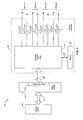
- the signal processing system 600 may comprise an analog-to-digital converter (A/D) 602, an adaptive feed-forward equalizer (FFE) 604, a 3 NEXT canceller 606, an adder 608, an ECHO canceller 610, and an equalizer/trellis decoder 612.
- A/D analog-to-digital converter
- FFE adaptive feed-forward equalizer
- 3 NEXT canceller 606 an adder 608, an ECHO canceller 610
- the A/D 602 may comprise suitable logic, circuitry, and/or code that may enable converting analog signals received via a twisted-pair wire into digital signals.
- the output of the A/D 602 may be communicated to the FFE 604.
- the FFE 604 may comprise suitable logic, circuitry, and/or code that may enable removal of precursor ISI to make the channel minimum-phase and to whiten the noise in the channel.
- the 3 NEXT canceller 606 may comprise suitable logic, circuitry, and/or code that may enable canceling at least a portion of the NEXT component received in the twisted-pair wire from the local transmitters corresponding to the three adjacent twisted-pair wires.
- the ECHO canceller 610 may comprise suitable logic, circuitry, and/or code that may enable canceling at least a portion of the ECHO component received in the twisted-pair wire from the local transmitter on the same twisted-pair wire.
- the adder 608 may comprise suitable logic, circuitry, and/or code that may enable adding the output of the FFE 604, the 3 NEXT canceller 606, and/or the ECHO canceller to generate a postcursor channel impulse response, Z n,1 .
- the equalizer/trellis decoder 612 may comprise suitable logic, circuitry and/or code that may enable equalizing the ISI that may result from the postcursor impulse response and decoding the trellis code.
- the equalizer/trellis decoder 612 may receive as inputs the postcursor channel impulse responses, Z n,2 , Z n,3 , and Z n,4 the corresponding to the other twisted-pair wires.
- the equalizer/trellis decoder 612 may generate the detected bits that correspond to the received analog signal.
- FIG. 6B is a block diagram illustrating exemplary separate equalization and decoding signal processing operations, in accordance with an embodiment of the invention.
- the equalizer/trellis decoder 612 may comprise four decision-feedback equalizers (DFE) 620 and a trellis-coded modulation (TCM) decoder 622.
- the DFE 620 may comprise suitable logic, circuitry, and/or code that may enable removing the postcursor ISI for each twisted-pair wire.
- the TCM decoder 622 may comprise suitable logic, circuitry, and/or code that may enable executing a Viterbi algorithm on the code trellis to decode the trellis-coded symbols.
- the TCM decoder 622 may be implemented using a parallel decision-feedback decoding architecture, for example.
- the separate equalization and trellis decoding approach may provide low implementation complexity and higher data rates, such as Gbps, for example, may be easily achieved.
- FIG. 6C is a block diagram illustrating exemplary joint equalization and decoding signal processing operations, in accordance with an embodiment of the invention.
- the equalizer/trellis decoder 612 may comprise a decision-feedback prefilter (DFP) block 650 and a look-ahead parallel decision-feedback decoder (LA-PDFD) 652.
- the DFP block 650 may comprise four DFPs 654, one for each twisted-pair wire.
- the DFP 654 may comprise suitable logic, circuitry, and/or code that may enable shortening the postcursor channel memory.
- the LA-PDFP 652 may comprise suitable logic, circuitry, and/or code that may enable computing branch metrics in a look-ahead fashion. The training and adaptation of the channel coefficients may be utilized to improve the performance of the equalizer/trellis decoder 612.
- FIG. 7 is a block diagram of a multi-rate Ethernet system for asymmetric data traffic that utilizes Gigabit signal processing resources in a four-pair extended range mode, in accordance with an embodiment of the invention.
- an asymmetric multi-rate Ethernet system 700 may comprise an upstream link partner 701a and a downstream link partner 701 b.
- the upstream link partner 701 a may correspond to, for example, the entry point switch 202 in FIG. 2, while the downstream link partner 701 b may correspond to, for example, a CPE 20.
- the asymmetric multi-rate Ethernet system 700 may support a plurality of asymmetric data rates or modes of operation over four-pair twisted-pair wire, including the ability to provide 1 Gbps or 10 Gbps, for example.
- the asymmetric multi-rate Ethernet system 700 may operate in an extended range mode of operation that provides 10 Mbps in the downstream direction and 2 Mbps in the upstream direction, for example.
- the extended range operation may be achieved by utilizing the 2 Mbps and 10 Mbps lower communication data rates, that is, data rates below the 1 Gbps or 10 Gbps that may be achieved by the signal processing operations enabled in either the upstream link partner 701 a or the downstream link partner 701 b.
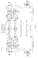
- the upstream link partner 701a may comprise four hybrids 506 as described in FIG. 5. Notwithstanding, the invention is not so limited and may support various implementations of a hybrid circuitry. Each hybrid 506 in the upstream link partner 701 a may be communicatively coupled to a transmitter 502a, a receiver 504a, and to one of the four twisted-pair wires 510 also as described in FIG. 5. Associated with each hybrid 506 in the upstream link partner 701 a may also be an echo canceller 702a and a subtractor 704a. The upstream link partner 701 a may also comprise a demultiplexer (demux) 706a, an aligner 708a, and a multiplexer (mux) 710a.
- demux demultiplexer
- aligner 708a aligner 708a
- mux multiplexer
- the downstream link partner 701 b may comprise four hybrids 506. Each hybrid 506 in the downstream link partner 701 b may be communicatively coupled to a transmitter 502b, a receiver 504b, and to one of the four twisted-pair wires 510 as described in FIG. 5. Associated with each hybrid 506 in the downstream link partner 701 b are also an echo canceller 504b and a subtractor 506b.
- the remote link partner 701 b may also comprise a demux 706b, an aligner 708b, and a mux 710b
- the portions of the upstream link partner 701 a and downstream link partner 701 b shown in FIG. 7 may correspond to a portion of the physical (PHY) layer operations supported by the upstream link partner 701 a and downstream link partner 701 b respectively.
- the demux 706a may comprise suitable logic, circuitry, and/or code that may enable separating an exemplary 10 Mbps dowsnteam signal into four 2.5 Mbps signals for transmission over the four twisted-pair wires.
- the demux 706b may comprise suitable logic, circuitry, and/or code that may enable separating an exemplary 2 Mbps upstream signal into four 500 kbps signals for transmission over the four twisted-pair wires.
- the aligner 708a may comprise suitable logic, circuitry, and/or code that may enable aligning the 500 kbps signals received from each of the four twisted-pair wires by the upstream link partner 701 a.
- the aligner 708b may comprise suitable logic, circuitry, and/or code that may enable aligning the 2.5 Mbps signals received from each of the four twisted-pair wires by the downstream link partner 701 b.
- the mux 710a may comprise suitable logic, circuitry, and/or code that may enable combining the aligned 500 kbps signals from the aligner 708a to generate the received 2 Mbps upstream signal.
- the mux 710b may comprise suitable logic, circuitry, and/or code that may enable combining the aligned 2.5 Mbps signals from the aligner 708a to generate the received 10 Mbps downstream signal.
- the echo cancellers 702a and 702b may comprise suitable logic, circuitry, and/or code that may enable at least partial cancellation of the ECHO component in the corresponding signal received via the receivers 504a and 504b, respectively, associated with the same twisted-pair wire.
- the subtractors 704a and 704b may comprise suitable logic, circuitry, and/or code that may enable cancellation of the ECHO component from the received signal.
- the upstream link partner 701a may separate a 10 Mbps signal to be transmitted into four 2.5 Mbps signals via the demux 706a.
- Each signal to be transmitted is processed by a transmitter 502a before being communicated to the corresponding twisted-pair wire via a hybrid 506.
- the four transmitted signals may arrive at the downstream link partner 701 b, where each of the signals may be processed by a receiver 504b before echo cancellation occurs from the operation of a corresponding echo canceller 702b and subtractor 704b.
- the four received 2.5 Mbps signals may be aligned in the aligner 708b before being combined in the mux 710b into a 10 Mbps received downstream signal.
- the downstream link partner 701 b may separate a 2 Mbps signal to be transmitted into four 500 kbps signals via the demux 706b.
- Each signal to be transmitted may be processed by a transmitter 502b before being communicated to the corresponding twisted-pair wire via a hybrid 506.
- the four transmitted signals may arrive at the upstream link partner 701 a, where each of the signals may be processed by a receiver 504a before echo cancellation occurs from the operation of a corresponding echo canceller 702a and subtractor 704a.
- the four received 500 kbps signals may be aligned in the aligner 708a before being combined in the mux 710a into a 2 Mbps received upstream signal.
- the upstream link partner 701 a and the downstream link partner 701 b may communicate via all four twisted-pair wires 510 in full duplex operation to provide an aggregate of 2 Mbps for the upstream data rate and 10 Mbps for the downstream data rate. Reducing the communication rate to 2 Mbps and 10 Mbps from, for example, 100 Mbps or higher, while utilizing the higher communication rate PHY layer signal processing operations, may enable extending the range, that is, extending the standard length, of the twisted-pair wires 510.
- the asymmetric multi-rate operations of the upstream link partner 701a and a downstream link partner 701 b may support Gigabit PHY layer operations that may utilize multi-level signaling to transmit multiple bits per clock interval.
- PAM-5 may be used to transmit 2 bits per symbol and reduce the symbol rate to carry on each twisted-pair wire 510.
- multi-level signaling may be applied at 100 Mbps, 10 Mbps, or ⁇ 10 Mbps rates, that is, at lower communication rates, to permit operation at reduced symbol rates.
- 25 Mbps may be carried on a single twisted-pair wire at a 12.5 Msps symbol rate. Reducing the symbol rate enables transmission over longer cable ranges.
- the signal processing operations available in a Gigabit PHY layer may support 2, 3, 4, or 5 levels of signaling with no increase in complexity, for example.
- Reducing the communication rate may also enable utilizing cabling with higher insertion loss while maintaining the same standard length.
- a Category 5 cable may be utilized. Reducing the communication rate in one direction in the asymmetric data traffic to 100 Mbps, for example, may enable utilizing cabling with higher insertion loss than a Category 5 cabling while maintaining the 100 m length requirement under the IEEE 802.3 standard.
- the insertion loss of a twisted-pair wire cable increases as the square root of frequency. Insertion loss, in dB, is directly proportional to cable length.
- Applying Gigabit signal processing operation at 100 Mbps data rate may increase the cable range.
- NEXT cancellation operations also improve the SNR of each received signal and may be applied at 100 Mbps and 10 Mbps rates to achieve similar improvements in SNR and further extend the cable range at those reduced communication rates.
- the asymmetric multi-rate Ethernet system 700 need not be limited to achieving a lower communication rate in any one direction by evenly distributing the data rate over each of the four twisted-pair wires utilized.
- the asymmetric multi-rate Ethernet system 700 may achieve a lower communication rate by distributing the data rate unevenly over each of the four twisted-pair wires utilized. For example, for a 10 Mbps downstream data rate, the first twisted-pair wire may support 1 Mbps, the second twisted-pair wire may support 2 Mbps, the third twisted-pair wire may support 3 Mbps, and the fourth twisted-pair wire may support 4 Mbps, to achieve an aggregate of 10 Mbps.
- a similar approach may be followed for generating an aggregate upstream data rate from unevenly distributed data rates over each of the four twisted-pair wires utilized.
- the components in the upstream link partner 701a and/or the downstream link partner 701 b may be adapted to handle an unevenly distributed lower communication rate.
- FIG. 8 is a block diagram of an exemplary echo canceller in an upstream asymmetric multi-rate PHY with a 10 Mbps downstream data rate and a 2 Mbps upstream data rate, in connection with an embodiment of the invention.
- an echo canceller 806 in a portion of an asymmetric multi-rate transceiver in an upstream link partner that is utilized in a mode of operation that supports 10 Mbps downstream data rate and 2 Mbps upstream data rate.
- the echo canceller 806 may be implemented utilizing an N tap echo canceller architecture that utilizes N/5 multipliers, for example.
- the echo canceller 806 may utilize a plurality of registers 810, a plurality of multipliers 814, a plurality of delay taps 812, a plurality of adders 816, an output register 818, and a switch 820.
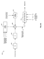
- the digital downstream signal may be converted to an analog downstream signal by the digital-to-analog converter (DAC) 802 for transmission via a twisted-pair copper wire 822.
- An analog upstream signal may be received by an analog-to-digital converter (ADC) 804 for conversion to a digital upstream signal in the upstream link partner.
- ADC analog-to-digital converter
- the digital upstream signal and the output signal generated by the echo canceller 806 may be added in the adder 808 to reduce the ECHO component in the received digital upstream signal.
- FIG. 9 is a block diagram of a multi-rate Ethernet system for asymmetric data traffic that utilizes Gigabit signal processing resources in a two-pair extended range mode, in accordance with an embodiment of the invention.
- an asymmetric multi-rate Ethernet system 900 may comprise an upstream link partner 901 a and a downstream link partner 901 b.
- the asymmetric multi-rate Ethernet system 900 may support up to 1 Gbps or 10 Gbps of asymmetric data traffic, for example.
- the asymmetric multi-rate Ethernet system 900 may also support other modes of operation, such as a lower asymmetric transmission rate over two-pair twisted-pair wire.
- the asymmetric multi-rate Ethernet system 900 may support a lower communication rate, such as 10 Mbps downstream data rate and 2 Mbps upstream data rate, while utilizing the signal processing operations available in the asymmetric multi-rate PHY layer for processing the higher communication rate, such as 1 Gbps or 10 Gbps when available.
- the upstream link partner 901 a and the downstream link partner 901 b may communicate via two twisted-pair wires 510 in full duplex operation at 5 Mbps downstream data rate at each wire to provide an aggregate downstream data rate of 10 Mbps and at 1 Mbps upstream data rate at each wire to provide an aggregate upstream data rate of 2 Mbps.
- the upstream link partner 901 a may utilize two hybrids 506 with corresponding echo canceller 902a and a subtractor 904a.
- the upstream link partner 901 a may also utilize a demux 906a, an aligner 908a, and a mux 910a for transmission and reception of signals at the reduced asymmetric communication rate.
- the downstream link partner 901 b may utilize two hybrids 506 with corresponding echo canceller 902b and a subtractor 904b.
- the downstream link partner 901 b may also utilize a demux 906b, an aligner 908b, and a mux 910b for transmission and reception of signals at the reduced asymmetric communication rate.
- the two remaining twisted-pair wires may remain unused in the asymmetric multi-rate Ethernet system 900.
- the asymmetric multi-rate Ethernet system 900 need not be limited to achieving a lower asymmetric communication rate by evenly distributing the data rate over each of the two twisted-pair wires utilized.
- the asymmetric multi-rate Ethernet system 800 may achieve a lower communication rate by distributing the upstream and downstream data rates unevenly over each of the two twisted-pair wires utilized.
- the first twisted-pair wire may support a 4 Mbps downstream data rate while the second twisted-pair wire may support 6 Mbps downstream data rate, to achieve an aggregate of 10 Mbps.
- the first twisted-pair wire may support a 800 kbps upstream data rate while the second twisted-pair wire may support 1.2 Mbps upstream data rate, to achieve an aggregate of 2 Mbps
- the components in the upstream link partner 901 a and/or the downstream link partner 901 b may be adapted to handle an unevenly distributed lower communication rate with asymmetric data traffic.
- FIG. 10 is a flow diagram illustrating exemplary steps in communication rate reduction to achieve extended range in Ethernet systems that utilize asymmetric multi-rate PHYs, in accordance with an embodiment of the invention.
- a flow diagram 1000 After start step 1002, in step 1004, an asymmetric Gigabit Ethernet transceiver may be enabled.
- the Gigabit Ethernet transceiver may utilize an asymmetric multi-rate PHY layer that enables reducing the communication rate from, for example, 1 Gbps to a lower communication rate.
- the lower communication rate may be a 10 Mbps downstream data rate and a 2 Mbps upstream data rate, for example, but need not be so limited.
- the asymmetric multi-rate PHY layer may also enable reduction of the symbol rate for the asymmetric Gigabit Ethernet transceiver.
- the asymmetric multi-rate PHY layer enables the application of Gigabit signal processing operations to the reduced communication or symbol rate.
- an extended range mode may be enabled in the asymmetric Gigabit Ethernet transceiver whereby the asymmetric multi-rate PHY layer reduces the communication rate and/or the symbol rate in at least one of the communication directions.
- at least a portion of the asymmetric Gigabit signal processing operations available in the asymmetric multi-rate PHY layer may be utilized during the extended range mode to enable the use of longer cables or to enable the use of higher insertion loss cables at the standard length. After step 1008, the process may proceed to end step 1010.
- Various embodiments of the invention may be utilized to extend a range of asymmetric multi-rate PHYs in Ethernet transceivers, such as ⁇ 10 Mpbs, 10 Mbps, 100 Mbps, and 1000 Mbps, for example.
- the same techniques may also be utilized to extend the range of any arbitrary rate.
- Applications for extending the range of asymmetric multi-rate Ethernet PHYs may comprise: backhaul, multi-tenant unit (MTU) FTTX+LAN, VDSL replacement, and/or generally networks that utilize switches, hubs, and/or repeaters to extend the distance of a point-to-point connection to greater than 100 meters.
- MTU multi-tenant unit
- VDSL replacement multi-tenant unit
- asymmetric multi-rate PHYs in Ethernet transceivers on both ends of an asymmetric Ethernet link may differ in speeds, error correction coding, equalization complexity, crosstalk cancellation complexity, and/or line code, for example.
- An asymmetric Ethernet transceiver that supports extended range via its asymmetric PHY layer operations may facilitate the elimination of switches used purely as network extenders, thereby saving on cost.
- single pair operation may be utilized to replace DSL equipment with less expensive Ethernet equipment.
- various features for extended range may be built into an asymmetric Gigabit PHY layer architecture with minimal overhead. This permits extended ranges applications to enjoy the cost reduction possible with a high volume part.
- the present invention may be realized in hardware, software, or a combination of hardware and software.
- the present invention may be realized in a centralized fashion in at least one computer system, or in a distributed fashion where different elements are spread across several interconnected computer systems. Any kind of computer system or other apparatus adapted for carrying out the methods described herein is suited.
- a typical combination of hardware and software may be a general-purpose computer system with a computer program that, when being loaded and executed, controls the computer system such that it carries out the methods described herein.
- the present invention may also be embedded in a computer program product, which comprises all the features enabling the implementation of the methods described herein, and which when loaded in a computer system is able to carry out these methods.
- Computer program in the present context means any expression, in any language, code or notation, of a set of instructions intended to cause a system having an information processing capability to perform a particular function either directly or after either or both of the following: a) conversion to another language, code or notation; b) reproduction in a different material form.
Landscapes
- Engineering & Computer Science (AREA)
- Signal Processing (AREA)
- Computer Networks & Wireless Communication (AREA)
- Multimedia (AREA)
- Small-Scale Networks (AREA)
- Communication Control (AREA)
- Cable Transmission Systems, Equalization Of Radio And Reduction Of Echo (AREA)
Abstract
Description
- This patent application makes reference to
United States Patent Application Serial No. 11/473,205 filed on June 22, 2006 - The above stated application is hereby incorporated by reference in its entirety.
- Certain embodiments of the invention relate to high-speed wired communication. More specifically, certain embodiments of the invention relate to a method and system for an asymmetric PHY in extended reach Ethernet local area networks (LANs).
- As the number of devices connected to data networks increase and higher data rates are required, there is a growing need for new transmission technologies enabling higher transmission rates over existing copper cabling infrastructures. Various efforts exist in this regard, including technologies that enable transmission rates that may even exceed Gigabit-per-second (Gbps) data rates over existing cabling. For example, the IEEE 802.3 standard defines the (Medium Access Control) MAC interface and physical layer (PHY) for Ethernet connections at 10 Mbps, 100 Mbps; 1 Gbps, and 10 Gbps data rates over twisted-
pair copper cabling 100 m in length. With each 10x rate increase more sophisticated signal processing is required to maintain the 100 m standard cable range. However, connections longer than 100 m may require either the use of fiber or the placement of Ethernet switches, hubs, and/or repeaters, at mid-points in the connection to keep all cables less than 100 m in length. - Other efforts include the development of a standard for 10 Gigabit-per-second (Gbps) Ethernet transmission over twisted-pair cabling (10GBASE-T). The emerging 10GBASE-T PHY specification is intended to enable 10 Gbps connections over twisted-pair cabling at distances of up to 182 feet for existing cabling, and at distances of up to 330 feet for new cabling, for example. To achieve full-duplex transmission at 10 Gbps over four-pair twisted-pair copper cabling, elaborate digital signal processing techniques are needed to remove or reduce the effects of severe frequency-dependent signal attenuation, signal reflections, near-end and far-end crosstalk between the four pairs, and external signals coupled into the four pairs either from adjacent transmission links or other external noise sources. Although, new cabling specifications are being developed to diminish susceptibility to external electro-magnetic interferences, existing systems can become expensive due to the various signal processing techniques that are employed to reduce the effects listed previously. Even with these techniques, current demand for much greater operating distances still remains unsatisfied.
- There may be instances where the data rate required for transmission in one direction may be much higher than the data rate required for transmission in the opposite direction, such as the delivery of interactive video from a central office to the consumer, for example. In this regard, the data rate for the transmission of video in one direction may be much higher than the data rate required for transmitting interactive commands in the opposite direction. Current IEEE 802.3 Ethernet standards define only symmetric links capable of supporting equal data rates in both directions. As a result, a receiver of lower data rates may support higher computational complexity than may be required of a receiver designed to receive a lower data rate.
- Further limitations and disadvantages of conventional and traditional approaches will become apparent to one of skill in the art, through comparison of such systems with some aspects of the present invention as set forth in the remainder of the present application with reference to the drawings.
- A system and/or method is provided for an asymmetric PHY in extended reach Ethernet local area networks (LANs), substantially as shown in and/or described in connection with at least one of the figures, as set forth more completely in the claims.
A method for wired communication is provided, the method comprising: - reducing a communication rate of an asymmetric multi-rate PHY from a higher communication rate to a lower communication rate; and
- applying signal processing operations supported by said asymmetric multi-rate PHY associated with said higher communication rate to said lower communication rate.
- reducing a communication rate of an asymmetric multi-rate PHY from a higher communication rate to a lower communication rate; and
- applying signal processing operations supported by said asymmetric multi-rate PHY associated with said higher communication rate to said lower communication rate.
- circuitry within an asymmetric multi-rate PHY that enables reducing a communication rate from a higher communication rate to a lower communication rate; and
- circuitry within said asymmetric multi-rate PHY that enables applying signal processing operations supported by said asymmetric multi-rate PHY associated with said higher communication rate to said lower communication rate.
- These and other advantages, aspects and novel features of the present invention, as well as details of an illustrated embodiment thereof, will be more fully understood from the following description and drawings.
- FIG. 1 is a block diagram illustrating an exemplary local area network configuration for a multi-tenant unit (MTU), in connection with an embodiment of the invention.
- FIG. 2 is a block diagram illustrating an exemplary extended range local area network configuration for an MTU with asymmetric data traffic, in accordance with an embodiment of the invention.
- FIG. 3 is a block diagram illustrating an Ethernet system over twisted-pair cabling link between an upstream link partner and a downstream link partner for extended range asymmetric data traffic, in connection with an embodiment of the invention.
- FIG. 4 is a block diagram illustrating an exemplary Ethernet transceiver architecture comprising an asymmetric multi-rate PHY, in accordance with an embodiment of the invention.
- FIG. 5 is a block diagram illustrating ECHO, NEXT, and FEXT channel conditions in an Ethernet system, in accordance with an embodiment of the invention.
- FIG. 6A is a block diagram illustrating exemplary Gigabit signal processing operations for received signals in an Ethernet system utilized for asymmetric data traffic, in accordance with an embodiment of the invention.
- FIG. 6B is a block diagram illustrating exemplary separate equalization and decoding signal processing operations, in accordance with an embodiment of the invention.
- FIG. 6C is a block diagram illustrating exemplary joint equalization and decoding signal processing operations, in accordance with an embodiment of the invention.
- FIG. 7 is a block diagram of a multi-rate Ethernet system for asymmetric data traffic that utilizes Gigabit signal processing resources in a four-pair extended range mode, in accordance with an embodiment of the invention.
- FIG. 8 is a block diagram of an exemplary echo canceller in an upstream asymmetric multi-rate PHY with a 10 Mbps downstream data rate and a 2 Mbps upstream data rate, in connection with an embodiment of the invention.
- FIG. 9 is a block diagram of a multi-rate Ethernet system for asymmetric data traffic that utilizes Gigabit signal processing resources in a two-pair extended range mode, in accordance with an embodiment of the invention.
- FIG. 10 is a flow diagram illustrating exemplary steps in communication rate reduction to achieve extended range in Ethernet systems that utilize asymmetric multi-rate PHYs, in accordance with an embodiment of the invention.
- Certain embodiments of the invention may be found in a method and system for an asymmetric PHY in extended reach Ethernet local area networks (LANs). Certain aspects of the invention may comprise reducing the communication rate provided by an asymmetric Ethernet multi-rate PHY in an Ethernet transceiver to enable extending the standard distance over twisted-pair cabling where customer premises equipment (CPE) may be located in the MTU. Downstream and upstream rates may be aggregated evenly or unevenly over each twisted-pair wire in the copper cabling. The asymmetric Ethernet multi-rate PHY may support signal-processing operations in its higher communication rate operations, such as echo cancellation and/or equalization, which may be applied to the reduced communication rate to enable range extension. The reduced communication rate may be achieved by reducing the symbol rate provided by the asymmetric Ethernet multi-rate PHY. Reducing the communication rate may also enable utilizing cabling with greater insertion loss than those used for a standard connection distance.
- Novel PHY devices for Ethernet applications that may enable extending the operational range beyond standard distances may enable cost reduction benefits when utilized and deployed in local area networks in the broadband access market and possibly in new residential and enterprise applications, such as providing central office (CO) services to customer premises equipment (CPE) in multi-tenant units (MTU), for example.
- FIG. 1 is a block diagram illustrating an exemplary local area network configuration for a multi-tenant unit (MTU), in connection with an embodiment of the invention. Referring to FIG. 1, there is shown a local area network configuration in an
MTU 100 that may comprise anentry point switch 102, a point-to-point (PP)bridge 104, a plurality of mid-span switch/repeaters 106a, ..., 106b, and 106c, and a plurality ofCPEs 108. - The
entry point switch 102 may comprise suitable logic, circuitry, and/or code that may enable communicating data between a central office (CO) and the plurality ofCPEs 108 within local area network in theMTU 100. In this regard, theentry point switch 102 may communicate with a central office via an Internet service provider (ISP) by utilizing a broadband access link or connection such as a Gigabit passive optical network (GPON) or an Ethernet passive optical network (EPON), for example. ThePP bridge 104 may comprise suitable logic, circuitry, and/or code that may enable data communication between theentry point switch 102 and the plurality of mid-span switch/repeaters 106a, ..., 106b, and 106c. Each of the plurality of mid-span switch/repeaters 106a, ..., 106b, and 106c may comprise suitable logic, circuitry, and/or code that may enable data communication between thePP bridge 104 and the plurality ofCPEs 108. Each of the plurality ofCPEs 108 may comprise suitable logic, circuitry, and/or code that may enable customer equipment associated with theCPE 108, such as computers, for example, to communicate with the central office via the local area network configured within theMTU 100. In this regard, theCPEs 108 may provide the customer with ports to plug in their equipment for communicating with the service provider and/or may also provide the service provider with the ability to monitor the connectivity to the customer site. - In the exemplary embodiment disclosed with respect to FIG. 1, the mid-span switch/
repeater 106a may be communicatively coupled to aplurality CPEs 108. Each of theCPEs 108 coupled to the mid-span switch/repeater 106a may comprise aunit switch 110 that may comprise suitable logic, circuitry, and/or code that may enable communication between a user or customer equipment, such as acomputer 112, for example, and the mid-span switch/repeater 106a. Notwithstanding the local area network configuration described in FIG. 1, other local area network configurations may be utilized in theMTU 100. - The
entry point switch 102, thePP bridge 104, the plurality of mid-span switch/repeaters 106a, ..., 106b, and 106c, and the plurality ofCPEs 108 may be communicatively coupled via four-wire twisted-pair cabling, for example. In this regard, the distance between theentry point switch 102 and one of the plurality of mid-span switch/repeaters 106a, ..., 106b, and 106c for standard Ethernet applications may generally extend up to approximately 100 meters. Moreover, the distance between aCPE 108 and one of the plurality of mid-span switch/repeaters 106a, ..., 106b, and 106c for standard Ethernet applications may also generally extend up to approximately 100 meters. Extending the range or distance that may be achieved over twisted-pair cabling for Ethernet applications may enable a local area network configuration within theMTU 100 that enables connecting theentry point switch 102 to aCPE 108 without the need for a mid-span switch/repeater. This approach may result in reduced costs in implementing the local area network configuration within theMTU 100, for example. - In some instances, more data may be transmitted from the central office to a CPE within the
MTU 100, which may be referred to as a downstream data traffic direction, than from a CPE to the central office, which may be referred to as a upstream data traffic direction, or from one CPE to another CPE. For example, central office services such as video-on-demand or Internet protocol television (IPTV) may result in an asymmetric data pattern or traffic within a local area network, such as the local area network within theMTU 100. In this regard, aCPE 108 within theMTU 100 may receive high data rate traffic from theentry point switch 102 while theentry point switch 102 may receive low data rate traffic from aCPE 108. In such an instance, it may be possible to utilize a simpler implementation of theentry point switch 102 that utilizes fewer signal processing operations and/or operates at lower speeds in order to reduce the overall cost and/or power consumption of the local area network configuration in theMTU 100. - A simplification of the entry point switch design, such as the
entry point switch 102, for example, for asymmetric data traffic may result from the lower complexity in the transmitter portion of a transceiver utilized for data communication over twisted pair copper cabling compared to that of the receiver portion of the transceiver. In this regard, the simpler transmitter portion may handle the high rate data traffic while the more complex receiver portion may handle the lower rate data traffic. Since the high rate data traffic may be handled without adding complexity to the transceiver, a transceiver utilized for asymmetric data traffic applications may result in designs that may achieve reduced integrated circuit area and power consumption when compared to those for symmetric data traffic applications. A simpler transceiver design for an entry point switch may enable a larger number of ports to be integrated into a single integrated circuit, enabling higher port density that may further reduce the cost and/or operation of a local area network within theMTU 100, for example. Standard Ethernet local area networks are generally defined for symmetric data traffic and may not benefit from the asymmetric data traffic of many MTU and enterprise local area network configurations. - Moreover, asymmetric data traffic may also enable the use of different forward error correction (FEC) schemes in the upstream direction than in the downstream direction. Generally, an FEC encoder may be much simpler to implement than the corresponding FEC decoder. When a stronger coding scheme is used in the downstream direction to permit a higher and/or more reliable downstream data rate, most of the complexity of utilizing a stronger coding scheme may be implemented in the decoder in the CPE transceiver. The entry point switch transceiver, which comprises the coding scheme encoder, may remain relatively simple to implement. This also enables a larger number of ports to be integrated onto a single transceiver integrated circuit in the entry point switch to provide higher port density and further reduce the cost of the local area network.
- FIG. 2 is a block diagram illustrating an exemplary extended range local area network configuration for an MTU with asymmetric data traffic, in accordance with an embodiment of the invention. Referring to FIG. 2, there is shown a local area network configuration in an
MTU 200 that may comprise anentry point switch 202, a point-to-point (PP)bridge 204, a plurality ofPP bridges 206a, ..., 206b, 206c, and 206d, and a plurality ofCPEs 208. - The
entry point switch 202 may comprise suitable logic, circuitry, and/or code that may enable asymmetrically communicating data between a CO and the plurality ofCPEs 208 within local area network in theMTU 200. For example, the downstream data traffic in the direction from theentry point switch 202 to aCPE 208 may be a higher data traffic than the upstream data traffic in the direction from aCPE 208 to theentry point switch 202. Moreover, theentry point switch 202 may enable adjusting multi-rate operations for extending the communication range or distance over four-wire twisted-pair copper cabling. Theentry point switch 202 may communicate with a central office via an ISP by utilizing a broadband access link or connection such as a Gigabit passive optical network (GPON) or an Ethernet passive optical network (EPON), for example. - The
PP bridge 204 may comprise suitable logic, circuitry, and/or code that may enable asymmetric data communication between theentry point switch 102 and the plurality ofPP bridges 206a, ..., 206b, 206c, and 206d. Each of the plurality ofPP bridges 206a, ..., 206b, 206c, and 206d may comprise suitable logic, circuitry, and/or code that may enable asymmetric data communication between thePP bridge 204 and the plurality ofCPEs 208. Each of the plurality ofCPEs 208 may comprise suitable logic, circuitry, and/or code that may enable customer equipment associated with theCPE 208, such as computers, for example, to asymmetrically communicate data with the central office via the local area network configured within theMTU 200. In this regard, theCPEs 208 may provide the customer with ports to plug in their equipment for communicating with the service provider and/or may also provide the service provider with the ability to monitor the connectivity to the customer site. - In the exemplary embodiment disclosed with respect to FIG. 2, the
PP bridge 206a may be communicatively coupled to a plurality ofCPEs 108. Each of theCPEs 108 coupled to thePP bridge 206a may comprise aunit switch 210 that may comprise suitable logic, circuitry, and/or code that may enable asymmetric data communication between a user or customer equipment, such as acomputer 212, for example, and thePP bridge 206a. In this regard, the downstream data traffic to theCPE 208 may be higher data rate traffic than the upstream data traffic to thePP bridge 206a. - The
entry point switch 202, thePP bridge 204, the plurality ofPP bridges 206a, ..., 206b, 206c, and 206d, and the plurality ofCPEs 208 may be communicatively coupled via four-wire twisted-pair cabling, for example. In this regard, the distance between thePP bridge 204 and one of the plurality ofCPEs 208 for asymmetric Ethernet applications may extend beyond approximately 100 meters enabling theentry point switch 202 to connect to aCPE 208 without the need for a mid-span switch/repeater, for example. - FIG. 3 is a block diagram illustrating an Ethernet system over twisted-pair cabling link between an upstream link partner and a downstream link partner for extended range asymmetric data traffic, in connection with an embodiment of the invention. Referring to FIG. 3, there is shown a
system 300 that comprises anupstream link partner 302 and adownstream link partner 304. Theupstream link partner 302 and thedownstream link partner 304 communicate via acable 312. Thecable 312 may be a four-pair unshielded twisted-pair (UTP) copper cabling, for example. Certain performance and/or specifications criteria for UTP copper cabling have been standardized. For example,Category 3 cabling may provide the necessary performance for 10 Mbps Ethernet transmissions over twisted-pair cabling (10BASE-T). In another example,Category 5 cabling may provide the necessary performance for 1000 Mbps, or Gbps, Ethernet transmissions over twisted-pair cabling (1000BASE-T). In most instances, a lower category cable may generally have a greater insertion loss than a higher category cable. - The
upstream link partner 302 may comprise acomputer system 306a, a medium access control (MAC)controller 308a, and a transceiver 304a. Thedownstream link partner 304 may comprise acomputer system 306b, aMAC controller 308b, and atransceiver 310b. Notwithstanding, the invention is not limited in this regard. - The
transceiver 310a may comprise suitable logic, circuitry, and/or code that may enable asymmetric Ethernet communication, such as transmission and reception of data, for example, between theupstream link partner 302 and thedownstream link partner 304, for example. In this regard, thetransceiver 310a may enable transmission at a high data rate to thedownstream link partner 304 while also enabling reception at a low data rate from thedownstream link partner 304. Similarly, thetransceiver 310b may comprise suitable logic, circuitry, and/or code that may enable asymmetric Ethernet communication between thedownstream link partner 304 and theupstream link partner 302, for example. In this regard, thetransceiver 310b may enable transmission at a low data rate to theupstream link partner 302 while also enabling reception at a high data rate from theupstream link partner 302. - The data transmitted and/or received by the
transceivers layer 1, or physical (PHY) layer, may provide services tolayer 2 andlayer 2 may provide services tolayer 3. In this regard, thetransceiver 310a may enable PHY layer operations that are utilized for asymmetric data communication with thedownstream link partner 304. Moreover, thetransceiver 310a may enable PHY layer operations that are utilized for asymmetric data communication with theupstream link partner 302. - The
transceivers transceivers transceivers transceivers - In the embodiment of the invention illustrated in FIG. 3, the
computer systems layer 3 and above, theMAC controllers layer 2 and above and thetransceivers layer 1 or the PHY layer. In this regard, thecomputer systems cable 312. Since each layer in the OSI model provides a service to the immediately higher interfacing layer, theMAC controllers computer systems transceivers - The
transceivers transceivers MAC controllers transceivers cable 312 and/or to decode data packets received from thecable 312. - The
MAC controller 308a may comprise suitable logic, circuitry, and/or code that may enable handling of data link layer,layer 2, operability and/or functionality in theupstream link partner 302. Similarly, theMAC controller 308b may comprise suitable logic, circuitry, and/or code that may enable handling oflayer 2 operability and/or functionality in thedownstream link partner 304. TheMAC controllers - The
MAC controller 308a may communicate with thetransceiver 310a via aninterface 314a and with thecomputer system 306a via abus controller interface 316a. TheMAC controller 308b may communicate with thetransceiver 310b via aninterface 314b and with thecomputer system 306b via abus controller interface 316b. Theinterfaces interfaces bus controller interfaces - FIG. 4 is a block diagram illustrating an exemplary Ethernet transceiver architecture comprising an asymmetric multi-rate PHY, in accordance with an embodiment of the invention. Referring to FIG. 4, there is shown a
link partner 400 that may comprise atransceiver 402, aMAC controller 404, acomputer system 406, aninterface 408, and abus controller interface 410. - The
transceiver 402 may be an integrated device that comprises an asymmetricmulti-rate PHY block 412, a plurality oftransmitters receivers memory 416, and amemory interface 418. The operation of thetransceiver 402 may be the same as or substantially similar to thetransceivers transceiver 402 is utilized in an upstream link partner, thetransceiver 402 may enable a high rate for data transmission and a low rate for data reception. In another example, when thetransceiver 402 is utilized in a downstream link partner, thetransceiver 402 may enable a low rate for data transmission and a high rate for data reception. In this regard, thetransceiver 402 may providelayer 1 or PHY layer operability and/or functionality that enables asymmetric data traffic. - Similarly, the operation of the
MAC controller 404, thecomputer system 406, theinterface 408, and thebus controller 410 may be the same as or substantially similar to therespective MAC controllers computer systems interfaces bus controller interfaces MAC controller 404, thecomputer system 406, theinterface 408, and thebus controller 410 may enable different data transmission and/or data reception rates when implemented in an upstream link partner or a downstream link partner. TheMAC controller 404 may comprise amulti-rate interface 404a that may comprise suitable logic, circuitry, and/or code to enable communication with thetransceiver 402 at a plurality of data rates via theinterface 408. - The asymmetric
multi-rate PHY block 412 in thetransceiver 402 may comprise suitable logic, circuitry, and/or code that may enable operability and/or functionality of PHY layer requirements for asymmetric data traffic. The asymmetricmulti-rate PHY block 412 may communicate with theMAC controller 404 via theinterface 408. In one aspect of the invention, theinterface 408 may be configured to utilize a plurality of serial data lanes for receiving data from the asymmetricmulti-rate PHY block 412 and/or for transmitting data to the asymmetricmulti-rate PHY block 412, in order to achieve higher operational speeds such as Gbps or 10 Gbps, for example. The asymmetricmulti-rate PHY block 412 may be configured to operate in one or more of a plurality of communication modes, where each communication mode implements a different communication protocol. These communication modes may include, but are not limited to, IEEE 802.3, 10GBASE-T, other similar protocols and/or non-standard communication protocols that enable asymmetric data traffic. The asymmetricmulti-rate PHY block 412 may be configured to operate in a particular mode of operation upon initialization or during operation. The asymmetricmulti-rate PHY block 412 may also be configured to operate in an extended range mode. - In some instances, an auto-negotiation scheme may be utilized by the
transceiver 402 to indicate or communicate to a remote link partner that thetransceiver 402 is operating in an extended range mode. The remote link partner may then configure itself to the appropriate extended range mode. Through auto-negotiation, a network link may be configured as an extended range from only one end of the link, ensuring interoperability between extended range enabled Ethernet transceivers and legacy devices. In some instances, the link may be pre-configured and the transceivers fixed in an extended range mode. - The asymmetric
multi-rate PHY block 412 may be coupled tomemory 416 through thememory interface 418, which may be implemented as a serial interface or a bus. Thememory 416 may comprise suitable logic, circuitry, and/or code that may enable storage or programming of information that includes parameters and/or code that may effectuate the operation of the asymmetricmulti-rate PHY block 412. The parameters may comprise configuration data and the code may comprise operational code such as software and/or firmware, but the information need not limited in this regard. Moreover, the parameters may include adaptive filter and/or block coefficients for use by the asymmetricmulti-rate PHY block 412, for example. - The
transmitters cable 312 in FIG. 3, for example. In this regard, when the transmitting link partner is an upstream link partner, thetransmitters transmitters - The
receivers cable 312, for example. In this regard, when the receiving link partner is an upstream link partner, thereceivers receivers - Each of the four pairs of transmitters and receivers in the
transceiver 402 may correspond to one of the four wires in thecable 312. For example,transmitter 414a andreceiver 414b may be utilized to asymmetrically communicate data with a remote link partner via the first wire pair in thecable 312. Similarly, transmitter 414g andreceiver 414h may be utilized to asymmetrically communicate data with a remote link partner via the fourth wire pair in thecable 312. In this regard, at least one of the four transmitter/receiver pairs may be enabled to provide the appropriate communication rate. The above-disclosed scheme may be applied to fewer, or greater, number of wires, for example. - FIG. 5 is a block diagram illustrating ECHO, NEXT, and FEXT channel conditions in an Ethernet system, in accordance with an embodiment of the invention. Referring to FIG. 5, there is shown an
asymmetric Ethernet system 500 that may comprise anupstream link partner 501a and adownstream link partner 501 b. Theupstream link partner 501 a and thedownstream link partner 501 b may asymmetrically communicate data via four twisted-pair wires 510 in full duplex operation. Each of the four twisted-pair wires 510 may support a portion of the data rates that may be necessary to provide the aggregate upstream and downstream data traffic. In this regard, each of the four twisted-pair wires 510 may support an equal or even or an unequal or uneven portion of the aggregate upstream and downstream data traffic. - The
upstream link partner 501a may comprise fourhybrids 506. Each hybrid 506 in theupstream link partner 501a may be communicatively coupled to atransmitter 502a, areceiver 504a, and to one of the four twisted-pair wires 510. Similarly, thedownstream link partner 501 b may comprise fourhybrids 506. Each hybrid 506 in thedownstream link partner 501 b may be communicatively coupled to atransmitter 502b, areceiver 504b, and to one of the four twisted-pair wires 510. The portions of theupstream link partner 501 a and thedownstream link partner 501 b shown in FIG. 5 may correspond to a portion of the physical (PHY) layer operations supported by theupstream link partner 501a and by thedownstream link partner 501b respectively. - Each hybrid 506 in the
upstream link partner 501 a or in thedownstream link partner 501 b may be communicatively coupled to or comprise atransformer 508. The hybrid 506 may comprise suitable logic, circuitry, and/or code that may enable separating the transmitted and received signals from a twisted-pair wire 510. Thetransmitters pair wire 510. In this regard, thetransmitters 502a may operate at a higher data rate than thetransmitters 502b. Thereceivers 304 may comprise suitable logic, circuitry, and/or code that may enable processing signals received from a link partner at the other end of the link via a twisted-pair wire 510 and a hybrid 506. In this regard, thereceivers 504a may operate at a lower data rate than thereceivers 504b. - During operation, several conditions may occur in each of the twisted-
pair wires 510. For example, intersymbol interference (ISI) may occur as a result of frequency dependent wire attenuation. As shown in FIG. 5, an ECHO component may be received in a twisted-pair wire 510 from an echo that results from thetransmitter 502a in theupstream link partner 501 a on the same twisted-pair wire 510. A near-end crosstalk (NEXT) component may also be received in a twisted-pair wire 510 from thelocal transmitters 502a corresponding to the three adjacent twisted-pair wires 510 in theupstream link partner 501a. Moreover, a far-end crosstalk (FEXT) component may also be received in a twisted-pair wire 510 from thetransmitters 502b in thedownstream link partner 501 b at the other end of the link. Similar conditions may also occur in thedownstream link partner 501 b, for example. - FIG. 6A is a block diagram illustrating exemplary Gigabit signal processing operations for received signals in an Ethernet system utilized for asymmetric data traffic, in accordance with an embodiment of the invention. Referring to FIG. 6A, there is shown a
signal processing system 600 that may provide a portion of the signal processing performed by the physical (PHY) layer operations in an Ethernet transceiver that supports asymmetric multi-rate operation. For example, thesignal processing system 600 may be implemented in the asymmetricmulti-rate PHY block 412 and/or in thereceivers signal processing system 600 may comprise an analog-to-digital converter (A/D) 602, an adaptive feed-forward equalizer (FFE) 604, a 3NEXT canceller 606, anadder 608, anECHO canceller 610, and an equalizer/trellis decoder 612. - The A/
D 602 may comprise suitable logic, circuitry, and/or code that may enable converting analog signals received via a twisted-pair wire into digital signals. The output of the A/D 602 may be communicated to theFFE 604. TheFFE 604 may comprise suitable logic, circuitry, and/or code that may enable removal of precursor ISI to make the channel minimum-phase and to whiten the noise in the channel. The 3NEXT canceller 606 may comprise suitable logic, circuitry, and/or code that may enable canceling at least a portion of the NEXT component received in the twisted-pair wire from the local transmitters corresponding to the three adjacent twisted-pair wires. TheECHO canceller 610 may comprise suitable logic, circuitry, and/or code that may enable canceling at least a portion of the ECHO component received in the twisted-pair wire from the local transmitter on the same twisted-pair wire. - The
adder 608 may comprise suitable logic, circuitry, and/or code that may enable adding the output of theFFE 604, the 3NEXT canceller 606, and/or the ECHO canceller to generate a postcursor channel impulse response, Zn,1. The equalizer/trellis decoder 612 may comprise suitable logic, circuitry and/or code that may enable equalizing the ISI that may result from the postcursor impulse response and decoding the trellis code. The equalizer/trellis decoder 612 may receive as inputs the postcursor channel impulse responses, Zn,2, Zn,3, and Zn,4 the corresponding to the other twisted-pair wires. The equalizer/trellis decoder 612 may generate the detected bits that correspond to the received analog signal. - FIG. 6B is a block diagram illustrating exemplary separate equalization and decoding signal processing operations, in accordance with an embodiment of the invention. Referring to FIG. 6B, there is shown the equalizer/
trellis decoder 612 as described in FIG. 6A that may be implemented as separate equalization and trellis decoding operations. The equalizer/trellis decoder 612 may comprise four decision-feedback equalizers (DFE) 620 and a trellis-coded modulation (TCM)decoder 622. TheDFE 620 may comprise suitable logic, circuitry, and/or code that may enable removing the postcursor ISI for each twisted-pair wire. TheTCM decoder 622 may comprise suitable logic, circuitry, and/or code that may enable executing a Viterbi algorithm on the code trellis to decode the trellis-coded symbols. TheTCM decoder 622 may be implemented using a parallel decision-feedback decoding architecture, for example. The separate equalization and trellis decoding approach may provide low implementation complexity and higher data rates, such as Gbps, for example, may be easily achieved. - FIG. 6C is a block diagram illustrating exemplary joint equalization and decoding signal processing operations, in accordance with an embodiment of the invention. Referring to FIG. 6C, there is shown the equalizer/
trellis decoder 612 as described in FIG. 6A that may be implemented as joint equalization and trellis decoding operations. The equalizer/trellis decoder 612 may comprise a decision-feedback prefilter (DFP) block 650 and a look-ahead parallel decision-feedback decoder (LA-PDFD) 652. TheDFP block 650 may comprise four DFPs 654, one for each twisted-pair wire. The DFP 654 may comprise suitable logic, circuitry, and/or code that may enable shortening the postcursor channel memory. The LA-PDFP 652 may comprise suitable logic, circuitry, and/or code that may enable computing branch metrics in a look-ahead fashion. The training and adaptation of the channel coefficients may be utilized to improve the performance of the equalizer/trellis decoder 612. - FIG. 7 is a block diagram of a multi-rate Ethernet system for asymmetric data traffic that utilizes Gigabit signal processing resources in a four-pair extended range mode, in accordance with an embodiment of the invention. Referring to FIG. 7, there is shown an asymmetric
multi-rate Ethernet system 700 that may comprise anupstream link partner 701a and adownstream link partner 701 b. Theupstream link partner 701 a may correspond to, for example, theentry point switch 202 in FIG. 2, while thedownstream link partner 701 b may correspond to, for example, a CPE 20. The asymmetricmulti-rate Ethernet system 700 may support a plurality of asymmetric data rates or modes of operation over four-pair twisted-pair wire, including the ability to provide 1 Gbps or 10 Gbps, for example. In the embodiment of the invention disclosed with respect to FIG. 7, the asymmetricmulti-rate Ethernet system 700 may operate in an extended range mode of operation that provides 10 Mbps in the downstream direction and 2 Mbps in the upstream direction, for example. In this regard, the extended range operation may be achieved by utilizing the 2 Mbps and 10 Mbps lower communication data rates, that is, data rates below the 1 Gbps or 10 Gbps that may be achieved by the signal processing operations enabled in either theupstream link partner 701 a or thedownstream link partner 701 b. - The
upstream link partner 701a may comprise fourhybrids 506 as described in FIG. 5. Notwithstanding, the invention is not so limited and may support various implementations of a hybrid circuitry. Each hybrid 506 in theupstream link partner 701 a may be communicatively coupled to atransmitter 502a, areceiver 504a, and to one of the four twisted-pair wires 510 also as described in FIG. 5. Associated with each hybrid 506 in theupstream link partner 701 a may also be anecho canceller 702a and asubtractor 704a. Theupstream link partner 701 a may also comprise a demultiplexer (demux) 706a, analigner 708a, and a multiplexer (mux) 710a. - Similarly, the
downstream link partner 701 b may comprise fourhybrids 506. Each hybrid 506 in thedownstream link partner 701 b may be communicatively coupled to atransmitter 502b, areceiver 504b, and to one of the four twisted-pair wires 510 as described in FIG. 5. Associated with each hybrid 506 in thedownstream link partner 701 b are also anecho canceller 504b and a subtractor 506b. Theremote link partner 701 b may also comprise ademux 706b, analigner 708b, and amux 710b The portions of theupstream link partner 701 a anddownstream link partner 701 b shown in FIG. 7 may correspond to a portion of the physical (PHY) layer operations supported by theupstream link partner 701 a anddownstream link partner 701 b respectively. - The demux 706a may comprise suitable logic, circuitry, and/or code that may enable separating an exemplary 10 Mbps dowsnteam signal into four 2.5 Mbps signals for transmission over the four twisted-pair wires. Similarly, the
demux 706b may comprise suitable logic, circuitry, and/or code that may enable separating an exemplary 2 Mbps upstream signal into four 500 kbps signals for transmission over the four twisted-pair wires. Thealigner 708a may comprise suitable logic, circuitry, and/or code that may enable aligning the 500 kbps signals received from each of the four twisted-pair wires by theupstream link partner 701 a. Similarly, thealigner 708b may comprise suitable logic, circuitry, and/or code that may enable aligning the 2.5 Mbps signals received from each of the four twisted-pair wires by thedownstream link partner 701 b. Themux 710a may comprise suitable logic, circuitry, and/or code that may enable combining the aligned 500 kbps signals from the aligner 708a to generate the received 2 Mbps upstream signal. Similarly, themux 710b may comprise suitable logic, circuitry, and/or code that may enable combining the aligned 2.5 Mbps signals from the aligner 708a to generate the received 10 Mbps downstream signal. - The
echo cancellers receivers - In operation, the
upstream link partner 701a may separate a 10 Mbps signal to be transmitted into four 2.5 Mbps signals via the demux 706a. Each signal to be transmitted is processed by atransmitter 502a before being communicated to the corresponding twisted-pair wire via ahybrid 506. The four transmitted signals may arrive at thedownstream link partner 701 b, where each of the signals may be processed by areceiver 504b before echo cancellation occurs from the operation of acorresponding echo canceller 702b andsubtractor 704b. The four received 2.5 Mbps signals may be aligned in thealigner 708b before being combined in themux 710b into a 10 Mbps received downstream signal. - Similarly, the
downstream link partner 701 b may separate a 2 Mbps signal to be transmitted into four 500 kbps signals via thedemux 706b. Each signal to be transmitted may be processed by atransmitter 502b before being communicated to the corresponding twisted-pair wire via ahybrid 506. The four transmitted signals may arrive at theupstream link partner 701 a, where each of the signals may be processed by areceiver 504a before echo cancellation occurs from the operation of acorresponding echo canceller 702a andsubtractor 704a. The four received 500 kbps signals may be aligned in thealigner 708a before being combined in themux 710a into a 2 Mbps received upstream signal. - The
upstream link partner 701 a and thedownstream link partner 701 b may communicate via all four twisted-pair wires 510 in full duplex operation to provide an aggregate of 2 Mbps for the upstream data rate and 10 Mbps for the downstream data rate. Reducing the communication rate to 2 Mbps and 10 Mbps from, for example, 100 Mbps or higher, while utilizing the higher communication rate PHY layer signal processing operations, may enable extending the range, that is, extending the standard length, of the twisted-pair wires 510. In this regard, the asymmetric multi-rate operations of theupstream link partner 701a and adownstream link partner 701 b may support Gigabit PHY layer operations that may utilize multi-level signaling to transmit multiple bits per clock interval. PAM-5 may be used to transmit 2 bits per symbol and reduce the symbol rate to carry on each twisted-pair wire 510. In this regard, multi-level signaling may be applied at 100 Mbps, 10 Mbps, or < 10 Mbps rates, that is, at lower communication rates, to permit operation at reduced symbol rates. For example, 25 Mbps may be carried on a single twisted-pair wire at a 12.5 Msps symbol rate. Reducing the symbol rate enables transmission over longer cable ranges. The signal processing operations available in a Gigabit PHY layer may support 2, 3, 4, or 5 levels of signaling with no increase in complexity, for example. - Reducing the communication rate may also enable utilizing cabling with higher insertion loss while maintaining the same standard length. For example, for Gigabit operations, a
Category 5 cable may be utilized. Reducing the communication rate in one direction in the asymmetric data traffic to 100 Mbps, for example, may enable utilizing cabling with higher insertion loss than aCategory 5 cabling while maintaining the 100 m length requirement under the IEEE 802.3 standard. The insertion loss of a twisted-pair wire cable increases as the square root of frequency. Insertion loss, in dB, is directly proportional to cable length. Applying Gigabit signal processing operation at 100 Mbps data rate may increase the cable range. NEXT cancellation operations also improve the SNR of each received signal and may be applied at 100 Mbps and 10 Mbps rates to achieve similar improvements in SNR and further extend the cable range at those reduced communication rates. - The asymmetric
multi-rate Ethernet system 700 need not be limited to achieving a lower communication rate in any one direction by evenly distributing the data rate over each of the four twisted-pair wires utilized. In another embodiment of the invention, the asymmetricmulti-rate Ethernet system 700 may achieve a lower communication rate by distributing the data rate unevenly over each of the four twisted-pair wires utilized. For example, for a 10 Mbps downstream data rate, the first twisted-pair wire may support 1 Mbps, the second twisted-pair wire may support 2 Mbps, the third twisted-pair wire may support 3 Mbps, and the fourth twisted-pair wire may support 4 Mbps, to achieve an aggregate of 10 Mbps. A similar approach may be followed for generating an aggregate upstream data rate from unevenly distributed data rates over each of the four twisted-pair wires utilized. In this regard, the components in theupstream link partner 701a and/or thedownstream link partner 701 b may be adapted to handle an unevenly distributed lower communication rate. - FIG. 8 is a block diagram of an exemplary echo canceller in an upstream asymmetric multi-rate PHY with a 10 Mbps downstream data rate and a 2 Mbps upstream data rate, in connection with an embodiment of the invention. Referring to FIG. 8, there is shown an
echo canceller 806 in a portion of an asymmetric multi-rate transceiver in an upstream link partner that is utilized in a mode of operation that supports 10 Mbps downstream data rate and 2 Mbps upstream data rate. Theecho canceller 806 may be implemented utilizing an N tap echo canceller architecture that utilizes N/5 multipliers, for example. In this regard, theecho canceller 806 may utilize a plurality ofregisters 810, a plurality ofmultipliers 814, a plurality of delay taps 812, a plurality ofadders 816, anoutput register 818, and aswitch 820. - The
echo canceller 806 may utilize a digital downstream signal that is based on a transmission clock, FTX, to generate an output signal via theswitch 820 to be communicated to anadder 808, where the output signal is based on a receive clock, FRX = FTX /5. The digital downstream signal may be converted to an analog downstream signal by the digital-to-analog converter (DAC) 802 for transmission via a twisted-pair copper wire 822. An analog upstream signal may be received by an analog-to-digital converter (ADC) 804 for conversion to a digital upstream signal in the upstream link partner. The digital upstream signal and the output signal generated by theecho canceller 806 may be added in theadder 808 to reduce the ECHO component in the received digital upstream signal. - FIG. 9 is a block diagram of a multi-rate Ethernet system for asymmetric data traffic that utilizes Gigabit signal processing resources in a two-pair extended range mode, in accordance with an embodiment of the invention. Referring to FIG. 9, there is shown an asymmetric
multi-rate Ethernet system 900 that may comprise anupstream link partner 901 a and adownstream link partner 901 b. The asymmetricmulti-rate Ethernet system 900 may support up to 1 Gbps or 10 Gbps of asymmetric data traffic, for example. The asymmetricmulti-rate Ethernet system 900 may also support other modes of operation, such as a lower asymmetric transmission rate over two-pair twisted-pair wire. In this regard, the asymmetricmulti-rate Ethernet system 900 may support a lower communication rate, such as 10 Mbps downstream data rate and 2 Mbps upstream data rate, while utilizing the signal processing operations available in the asymmetric multi-rate PHY layer for processing the higher communication rate, such as 1 Gbps or 10 Gbps when available. - The
upstream link partner 901 a and thedownstream link partner 901 b may communicate via two twisted-pair wires 510 in full duplex operation at 5 Mbps downstream data rate at each wire to provide an aggregate downstream data rate of 10 Mbps and at 1 Mbps upstream data rate at each wire to provide an aggregate upstream data rate of 2 Mbps. Theupstream link partner 901 a may utilize twohybrids 506 withcorresponding echo canceller 902a and asubtractor 904a. Theupstream link partner 901 a may also utilize a demux 906a, analigner 908a, and amux 910a for transmission and reception of signals at the reduced asymmetric communication rate. Similarly, thedownstream link partner 901 b may utilize twohybrids 506 withcorresponding echo canceller 902b and a subtractor 904b. Thedownstream link partner 901 b may also utilize ademux 906b, analigner 908b, and amux 910b for transmission and reception of signals at the reduced asymmetric communication rate. The two remaining twisted-pair wires may remain unused in the asymmetricmulti-rate Ethernet system 900. - The asymmetric
multi-rate Ethernet system 900 need not be limited to achieving a lower asymmetric communication rate by evenly distributing the data rate over each of the two twisted-pair wires utilized. In another embodiment of the invention, the asymmetric multi-rate Ethernet system 800 may achieve a lower communication rate by distributing the upstream and downstream data rates unevenly over each of the two twisted-pair wires utilized. For example, the first twisted-pair wire may support a 4 Mbps downstream data rate while the second twisted-pair wire may support 6 Mbps downstream data rate, to achieve an aggregate of 10 Mbps. Similarly, the first twisted-pair wire may support a 800 kbps upstream data rate while the second twisted-pair wire may support 1.2 Mbps upstream data rate, to achieve an aggregate of 2 Mbps In this regard, the components in theupstream link partner 901 a and/or thedownstream link partner 901 b may be adapted to handle an unevenly distributed lower communication rate with asymmetric data traffic. - FIG. 10 is a flow diagram illustrating exemplary steps in communication rate reduction to achieve extended range in Ethernet systems that utilize asymmetric multi-rate PHYs, in accordance with an embodiment of the invention. Referring to FIG. 10, there is shown a flow diagram 1000. After
start step 1002, instep 1004, an asymmetric Gigabit Ethernet transceiver may be enabled. The Gigabit Ethernet transceiver may utilize an asymmetric multi-rate PHY layer that enables reducing the communication rate from, for example, 1 Gbps to a lower communication rate. The lower communication rate may be a 10 Mbps downstream data rate and a 2 Mbps upstream data rate, for example, but need not be so limited. The asymmetric multi-rate PHY layer may also enable reduction of the symbol rate for the asymmetric Gigabit Ethernet transceiver. When reducing the communication rate or symbol rate, the asymmetric multi-rate PHY layer enables the application of Gigabit signal processing operations to the reduced communication or symbol rate. - In
step 1006, an extended range mode may be enabled in the asymmetric Gigabit Ethernet transceiver whereby the asymmetric multi-rate PHY layer reduces the communication rate and/or the symbol rate in at least one of the communication directions. Instep 1008, at least a portion of the asymmetric Gigabit signal processing operations available in the asymmetric multi-rate PHY layer may be utilized during the extended range mode to enable the use of longer cables or to enable the use of higher insertion loss cables at the standard length. Afterstep 1008, the process may proceed to endstep 1010. - Various embodiments of the invention may be utilized to extend a range of asymmetric multi-rate PHYs in Ethernet transceivers, such as < 10 Mpbs, 10 Mbps, 100 Mbps, and 1000 Mbps, for example. The same techniques may also be utilized to extend the range of any arbitrary rate. Applications for extending the range of asymmetric multi-rate Ethernet PHYs may comprise: backhaul, multi-tenant unit (MTU) FTTX+LAN, VDSL replacement, and/or generally networks that utilize switches, hubs, and/or repeaters to extend the distance of a point-to-point connection to greater than 100 meters. Moreover asymmetric multi-rate PHYs in Ethernet transceivers on both ends of an asymmetric Ethernet link may differ in speeds, error correction coding, equalization complexity, crosstalk cancellation complexity, and/or line code, for example.
- An asymmetric Ethernet transceiver that supports extended range via its asymmetric PHY layer operations may facilitate the elimination of switches used purely as network extenders, thereby saving on cost. In addition, single pair operation may be utilized to replace DSL equipment with less expensive Ethernet equipment. In accordance with various embodiments of the invention, various features for extended range may be built into an asymmetric Gigabit PHY layer architecture with minimal overhead. This permits extended ranges applications to enjoy the cost reduction possible with a high volume part.
- Accordingly, the present invention may be realized in hardware, software, or a combination of hardware and software. The present invention may be realized in a centralized fashion in at least one computer system, or in a distributed fashion where different elements are spread across several interconnected computer systems. Any kind of computer system or other apparatus adapted for carrying out the methods described herein is suited. A typical combination of hardware and software may be a general-purpose computer system with a computer program that, when being loaded and executed, controls the computer system such that it carries out the methods described herein.
- The present invention may also be embedded in a computer program product, which comprises all the features enabling the implementation of the methods described herein, and which when loaded in a computer system is able to carry out these methods. Computer program in the present context means any expression, in any language, code or notation, of a set of instructions intended to cause a system having an information processing capability to perform a particular function either directly or after either or both of the following: a) conversion to another language, code or notation; b) reproduction in a different material form.
- While the present invention has been described with reference to certain embodiments, it will be understood by those skilled in the art that various changes may be made and equivalents may be substituted without departing from the scope of the present invention. In addition, many modifications may be made to adapt a particular situation or material to the teachings of the present invention without departing from its scope. Therefore, it is intended that the present invention not be limited to the particular embodiment disclosed, but that the present invention will include all embodiments falling within the scope of the appended claims.
Advantageously, the method further comprises distributing said reduced communication rate over at least one of: an upstream portion and a downstream portion of said lower communication rate.
Advantageously, the method further comprises aggregating an upstream portion of said lower communication rate by evenly distributing said upstream portion over each twisted-pair wire utilized in a copper cabling.
Advantageously, the method further comprises aggregating a downstream portion of said lower communication rate by evenly distributing said downstream portion over each twisted-pair wire utilized in a copper cabling.
Advantageously, the method further comprises aggregating an upstream portion of said lower communication rate by unevenly distributing said upstream portion over each twisted-pair wire utilized in a copper cabling.
Advantageously, the method further comprises aggregating a downstream portion of said lower communication rate by unevenly distributing said downstream portion over each twisted-pair wire utilized in a copper cabling.
Advantageously, the method further comprises reducing said communication rate from a higher symbol rate to a lower symbol rate.
Advantageously, said signal processing operations associated with said higher communication rate comprise at least one of an ECHO cancellation operation, a NEXT cancellation operation, and a FEXT cancellation operations.
Advantageously, said signal processing operations associated with said higher communication rate comprise equalization operations.
Advantageously, the method further comprises communicating at said reduced communication rate via a cable type with a greater insertion loss than a cable type associated with said higher communication rate.
According to an aspect of the invention, a machine-readable storage is provided having stored thereon, a computer program having at least one code section for wired communication, the at least one code section being executable by a machine for causing the machine to perform steps comprising:
Advantageously, the machine-readable storage further comprises code for distributing said reduced communication rate over at least one of: an upstream portion and a downstream portion of said lower communication rate.
Advantageously, the machine-readable storage further comprises code for aggregating an upstream portion of said lower communication rate by evenly distributing said upstream portion over each twisted-pair wire utilized in a copper cabling.
Advantageously, the machine-readable storage further comprises code for aggregating a downstream portion of said lower communication rate by evenly distributing said downstream portion over each twisted-pair wire utilized in a copper cabling.
Advantageously, the machine-readable storage further comprises code for aggregating an upstream portion of said lower communication rate by unevenly distributing said upstream portion over each twisted-pair wire utilized in a copper cabling.
Advantageously, the machine-readable storage further comprises code for aggregating a downstream portion of said lower communication rate by unevenly distributing said downstream portion over each twisted-pair wire utilized in a copper cabling.
Advantageously, the machine-readable storage further comprises code for reducing said communication rate from a higher symbol rate to a lower symbol rate.
Advantageously, said signal processing operations associated with said higher communication rate comprise at least one of an ECHO cancellation operation, a NEXT cancellation operation, and a FEXT cancellation operations.
Advantageously, said signal processing operations associated with said higher communication rate comprise equalization operations.
According to an aspect of the invention, a system for wired communication is provided, the system comprising:
Advantageously, the system further comprises code for distributing said reduced communication rate over at least one of: an upstream portion and a downstream portion of said lower communication rate.
Advantageously, the system further comprises circuitry within said asymmetric multi-rate PHY that enables aggregating an upstream portion of said lower communication rate by evenly distributing said upstream portion over each twisted-pair wire utilized in a copper cabling.
Advantageously, the system further comprises circuitry within said asymmetric multi-rate PHY that enables aggregating a downstream portion of said lower communication rate by evenly distributing said downstream portion over each twisted-pair wire utilized in a copper cabling.
Advantageously, the system further comprises circuitry within said asymmetric multi-rate PHY that enables aggregating an upstream portion of said lower communication rate by unevenly distributing said upstream portion over each twisted-pair wire utilized in a copper cabling.
Advantageously, the system further comprises circuitry within said asymmetric multi-rate PHY that enables aggregating a downstream portion of said lower communication rate by unevenly distributing said downstream portion over each twisted-pair wire utilized in a copper cabling.
Advantageously, the system further comprises circuitry within said asymmetric multi-rate PHY that enables reducing said communication rate from a higher symbol rate to a lower symbol rate.
Advantageously, said signal processing operations associated with said higher communication rate comprise at least one of an ECHO cancellation operation, a NEXT cancellation operation, and a FEXT cancellation operations.
Advantageously, said signal processing operations associated with said higher communication rate comprise equalization operations.
Advantageously, the system further comprises circuitry within said asymmetric multi-rate PHY that enables communicating at said reduced communication rate via a cable type with a greater insertion loss than a cable type associated with said higher communication rate.
Claims (10)
- A method for wired communication, the method comprising:reducing a communication rate of an asymmetric multi-rate PHY from a higher communication rate to a lower communication rate; andapplying signal processing operations supported by said asymmetric multi-rate PHY associated with said higher communication rate to said lower communication rate.
- The method according to claim 1, wherein said asymmetric multi-rate PHY is an asymmetric Ethernet multi-rate PHY.
- The method according to claim 1, comprising distributing said reduced communication rate over at least one of: an upstream portion and a downstream portion of said lower communication rate.
- The method according to claim 1, comprising aggregating an upstream portion of said lower communication rate by evenly distributing said upstream portion over each twisted-pair wire utilized in a copper cabling.
- The method according to claim 1, comprising aggregating a downstream portion of said lower communication rate by evenly distributing said downstream portion over each twisted-pair wire utilized in a copper cabling.
- A machine-readable storage having stored thereon, a computer program having at least one code section for wired communication, the at least one code section being executable by a machine for causing the machine to perform steps comprising:reducing a communication rate of an asymmetric multi-rate PHY from a higher communication rate to a lower communication rate; andapplying signal processing operations supported by said asymmetric multi-rate PHY associated with said higher communication rate to said lower communication rate.
- The machine-readable storage according to claim 6, wherein said asymmetric multi-rate PHY is an asymmetric Ethernet multi-rate PHY.
- A system for wired communication, the system comprising:circuitry within an asymmetric multi-rate PHY that enables reducing a communication rate from a higher communication rate to a lower communication rate; andcircuitry within said asymmetric multi-rate PHY that enables applying signal processing operations supported by said asymmetric multi-rate PHY associated with said higher communication rate to said lower communication rate.
- The system according to claim 8, wherein said asymmetric multi-rate PHY is an asymmetric Ethernet multi-rate PHY.
- The system according to claim 8, comprising code for distributing said reduced communication rate over at least one of: an upstream portion and a downstream portion of said lower communication rate.
Applications Claiming Priority (1)
| Application Number | Priority Date | Filing Date | Title |
|---|---|---|---|
| US11/470,515 US8355404B2 (en) | 2006-09-06 | 2006-09-06 | Method and system for an asymmetric PHY in extended range ethernet LANs |
Publications (3)
| Publication Number | Publication Date |
|---|---|
| EP1898547A2 true EP1898547A2 (en) | 2008-03-12 |
| EP1898547A3 EP1898547A3 (en) | 2013-05-29 |
| EP1898547B1 EP1898547B1 (en) | 2020-01-22 |
Family
ID=38951724
Family Applications (1)
| Application Number | Title | Priority Date | Filing Date |
|---|---|---|---|
| EP07011332.9A Ceased EP1898547B1 (en) | 2006-09-06 | 2007-06-08 | Asymmetric wired communication with extended range |
Country Status (5)
| Country | Link |
|---|---|
| US (1) | US8355404B2 (en) |
| EP (1) | EP1898547B1 (en) |
| KR (1) | KR100904650B1 (en) |
| CN (1) | CN101166196B (en) |
| TW (1) | TWI445373B (en) |
Cited By (1)
| Publication number | Priority date | Publication date | Assignee | Title |
|---|---|---|---|---|
| WO2018042253A3 (en) * | 2016-09-02 | 2018-05-03 | Marvell World Trade Ltd. | Method and apparatus for full-duplex operation in a multipoint-to-multipoint network |
Families Citing this family (18)
| Publication number | Priority date | Publication date | Assignee | Title |
|---|---|---|---|---|
| US8553720B2 (en) | 2006-04-19 | 2013-10-08 | Marvell World Trade Ltd. | Adaptive speed control for MAC-PHY interfaces |
| US8565105B2 (en) * | 2008-09-29 | 2013-10-22 | Broadcom Corporation | Method and system for ethernet switching, conversion, and PHY optimization based on link length in audio/video systems |
| US8121178B2 (en) * | 2006-09-28 | 2012-02-21 | At&T Intellectual Property I, Lp | Method and system for sending data using a very high bit rate digital subscriber line |
| US7920597B2 (en) * | 2007-03-12 | 2011-04-05 | Broadcom Corporation | Method and system for low power idle signal transmission in ethernet networks |
| US8243752B2 (en) * | 2007-04-04 | 2012-08-14 | Marvell World Trade Ltd. | Long-reach ethernet for 1000BASE-T and 10GBASE-T |
| US20090097401A1 (en) * | 2007-10-12 | 2009-04-16 | Wael William Diab | Method and system for configurable data rate thresholds for energy efficient ethernet |
| US8588254B2 (en) * | 2007-12-17 | 2013-11-19 | Broadcom Corporation | Method and system for energy efficient signaling for 100mbps Ethernet using a subset technique |
| US8199770B2 (en) * | 2007-12-17 | 2012-06-12 | Broadcom Corporation | Method and system for asymmetric operation in a network node in an energy efficient ethernet network |
| US20090187807A1 (en) * | 2008-01-23 | 2009-07-23 | Texas Instruments Incorporated | Method for optimizing block coding parameters, a communications controller employing the method and a communications node and link employing the controller |
| US8262407B2 (en) * | 2009-12-01 | 2012-09-11 | Cisco Technology, Inc. | Active copper cable extender |
| US9042211B2 (en) * | 2009-12-17 | 2015-05-26 | Ikanos Communications, Inc. | Systems and methods of resource allocation for cancellation of crosstalk |
| US8145814B2 (en) * | 2010-07-16 | 2012-03-27 | Broadcom Corporation | Method and system for a configurable connnector for ethernet |
| US8958301B2 (en) * | 2011-10-28 | 2015-02-17 | Iii Holdings 2, Llc | System and method for dynamically power and performance optimized server interconnects |
| US9954631B2 (en) * | 2012-07-27 | 2018-04-24 | Adaptive Spectrum And Signal Alignment, Inc. | Management system and methods of managing time-division duplex (TDD) transmission over copper |
| CN103746723B (en) * | 2013-12-19 | 2016-03-30 | 天津光电通信技术有限公司 | Wired paths information draws the equipment of connecing |
| CN108476407B (en) * | 2015-10-28 | 2022-10-28 | 米兰综合工科大学 | Method and system for transmitting radio signals over copper cable |
| KR102464126B1 (en) | 2018-09-12 | 2022-11-07 | 삼성전자주식회사 | Apparatus for combining printed circuit boards |
| US10521391B1 (en) * | 2018-11-29 | 2019-12-31 | Apple Inc. | Chip to chip interface with scalable bandwidth |
Family Cites Families (23)
| Publication number | Priority date | Publication date | Assignee | Title |
|---|---|---|---|---|
| JPH1023022A (en) | 1996-07-03 | 1998-01-23 | Sony Corp | Switching apparatus and method |
| KR100211980B1 (en) * | 1996-12-06 | 1999-08-02 | 이계철 | Subscriber Registration Device of ATM Switching System Using UTOPIA |
| US5790363A (en) * | 1997-12-03 | 1998-08-04 | Tii Industries, Inc. | Ethernet overvoltage/overcurrent protection system |
| IL125227A0 (en) | 1998-07-06 | 1999-03-12 | Vitenberg Roman | Souce adaptive digital subscriber line and method |
| US6567464B2 (en) * | 1998-07-24 | 2003-05-20 | Compaq Information Technologies Group, L.P. | Fast retrain based on communication profiles for a digital modem |
| US6763097B1 (en) * | 1999-06-24 | 2004-07-13 | Coppergate Communications Ltd. | Source adaptive digital subscriber line and method |
| KR100618980B1 (en) | 1999-11-20 | 2006-08-31 | 삼성전자주식회사 | Apparatus and method for controlling data transmission rate between transmit / receive units in asymmetric digital subscriber line system |
| DE69915082D1 (en) * | 1999-12-14 | 2004-04-01 | St Microelectronics Nv | DSL transmission system with remote crosstalk compensation |
| US6795494B1 (en) * | 2000-05-12 | 2004-09-21 | National Semiconductor Corporation | Receiver architecture using mixed analog and digital signal processing and method of operation |
| EP3386128B1 (en) | 2001-10-05 | 2019-07-24 | TQ Delta, LLC | Systems and methods for multi-pair atm over dsl |
| DE10154644C2 (en) * | 2001-11-07 | 2003-12-11 | Siemens Ag | Method and device for optimized ADSL data transmission |
| AU2002364572A1 (en) | 2001-12-18 | 2003-07-09 | Globespan Virata Incorporated | System and method for rate enhanced shdsl |
| DE60301620T2 (en) | 2002-03-21 | 2006-06-14 | Ibm | METHOD AND SYSTEM FOR OPTIMIZING ADSL CONNECTIONS IN A DSLAM |
| US7260825B2 (en) * | 2002-07-08 | 2007-08-21 | Sbc Properties, L.P. | System for providing DBS and DSL video services to multiple television sets |
| US7388904B2 (en) | 2003-06-03 | 2008-06-17 | Vativ Technologies, Inc. | Near-end, far-end and echo cancellers in a multi-channel transceiver system |
| US7779162B2 (en) * | 2003-08-07 | 2010-08-17 | At&T Intellectual Property I, L.P. | Methods and systems for providing an asymmetric ethernet service |
| US7356047B1 (en) | 2004-04-24 | 2008-04-08 | Cisco Technology, Inc. | 10/100/1000/2500 Mbps serial media independent interface (SGMII) |
| US7403519B2 (en) * | 2004-05-04 | 2008-07-22 | Via Technologies Inc. | Asymmetric ethernet network data transfer system and method |
| US9369231B2 (en) * | 2005-01-13 | 2016-06-14 | Broadcom Corporation | Dynamic adjustment of transfer characteristics as a function of channel characteristics |
| US7301424B2 (en) | 2005-06-29 | 2007-11-27 | Intel Corporation | Flexible waveguide cable with a dielectric core |
| US7782852B2 (en) * | 2005-10-11 | 2010-08-24 | Teranetics, Inc. | Multiple modulation rate 10Gbase-T transmission |
| US7856028B2 (en) | 2005-11-17 | 2010-12-21 | Broadcom Corporation | Power dissipation management for wired transceivers |
| US8228795B2 (en) * | 2006-04-19 | 2012-07-24 | Broadcom Corporation | Method and system for extended reach copper transceiver |
-
2006
- 2006-09-06 US US11/470,515 patent/US8355404B2/en active Active
-
2007
- 2007-06-08 EP EP07011332.9A patent/EP1898547B1/en not_active Ceased
- 2007-08-29 CN CN200710148839XA patent/CN101166196B/en not_active Expired - Fee Related
- 2007-08-31 TW TW096132608A patent/TWI445373B/en not_active IP Right Cessation
- 2007-09-03 KR KR1020070088985A patent/KR100904650B1/en not_active Expired - Fee Related
Non-Patent Citations (1)
| Title |
|---|
| None |
Cited By (1)
| Publication number | Priority date | Publication date | Assignee | Title |
|---|---|---|---|---|
| WO2018042253A3 (en) * | 2016-09-02 | 2018-05-03 | Marvell World Trade Ltd. | Method and apparatus for full-duplex operation in a multipoint-to-multipoint network |
Also Published As
| Publication number | Publication date |
|---|---|
| HK1121601A1 (en) | 2009-04-24 |
| US20080056284A1 (en) | 2008-03-06 |
| CN101166196B (en) | 2011-04-13 |
| TW200828925A (en) | 2008-07-01 |
| CN101166196A (en) | 2008-04-23 |
| TWI445373B (en) | 2014-07-11 |
| EP1898547A3 (en) | 2013-05-29 |
| KR20080022508A (en) | 2008-03-11 |
| US8355404B2 (en) | 2013-01-15 |
| KR100904650B1 (en) | 2009-06-25 |
| EP1898547B1 (en) | 2020-01-22 |
Similar Documents
| Publication | Publication Date | Title |
|---|---|---|
| EP1898547B1 (en) | Asymmetric wired communication with extended range | |
| US8654636B2 (en) | Method and system for extended reach copper transceiver | |
| EP1903733B1 (en) | Method and system for an extended range ethernet line code | |
| US8867564B2 (en) | Method and system for an extended range ethernet link discovery signaling | |
| US9374614B2 (en) | Method and system for enabling video communication via ethernet utilizing asymmetrical physical layer operations | |
| US20110007664A1 (en) | Method and system for link adaptive ethernet communications | |
| US8218567B2 (en) | Method and system for reducing transceiver power via a variable signal constellation | |
| HK1121601B (en) | A method and system for wire communication | |
| HK1119504B (en) | Method and system for wire communication | |
| HK1119503B (en) | Method and system for wire communication |
Legal Events
| Date | Code | Title | Description |
|---|---|---|---|
| PUAI | Public reference made under article 153(3) epc to a published international application that has entered the european phase |
Free format text: ORIGINAL CODE: 0009012 |
|
| AK | Designated contracting states |
Kind code of ref document: A2 Designated state(s): AT BE BG CH CY CZ DE DK EE ES FI FR GB GR HU IE IS IT LI LT LU LV MC MT NL PL PT RO SE SI SK TR |
|
| AX | Request for extension of the european patent |
Extension state: AL BA HR MK YU |
|
| PUAL | Search report despatched |
Free format text: ORIGINAL CODE: 0009013 |
|
| AK | Designated contracting states |
Kind code of ref document: A3 Designated state(s): AT BE BG CH CY CZ DE DK EE ES FI FR GB GR HU IE IS IT LI LT LU LV MC MT NL PL PT RO SE SI SK TR |
|
| AX | Request for extension of the european patent |
Extension state: AL BA HR MK RS |
|
| RIC1 | Information provided on ipc code assigned before grant |
Ipc: H04L 5/14 20060101AFI20130419BHEP |
|
| 17P | Request for examination filed |
Effective date: 20131129 |
|
| RBV | Designated contracting states (corrected) |
Designated state(s): AT BE BG CH CY CZ DE DK EE ES FI FR GB GR HU IE IS IT LI LT LU LV MC MT NL PL PT RO SE SI SK TR |
|
| AKX | Designation fees paid |
Designated state(s): DE FR GB |
|
| STAA | Information on the status of an ep patent application or granted ep patent |
Free format text: STATUS: EXAMINATION IS IN PROGRESS |
|
| 17Q | First examination report despatched |
Effective date: 20170322 |
|
| RAP1 | Party data changed (applicant data changed or rights of an application transferred) |
Owner name: AVAGO TECHNOLOGIES GENERAL IP (SINGAPORE) PTE. LTD |
|
| RAP1 | Party data changed (applicant data changed or rights of an application transferred) |
Owner name: AVAGO TECHNOLOGIES INTERNATIONAL SALES PTE. LIMITE |
|
| GRAP | Despatch of communication of intention to grant a patent |
Free format text: ORIGINAL CODE: EPIDOSNIGR1 |
|
| STAA | Information on the status of an ep patent application or granted ep patent |
Free format text: STATUS: GRANT OF PATENT IS INTENDED |
|
| INTG | Intention to grant announced |
Effective date: 20190807 |
|
| GRAS | Grant fee paid |
Free format text: ORIGINAL CODE: EPIDOSNIGR3 |
|
| GRAA | (expected) grant |
Free format text: ORIGINAL CODE: 0009210 |
|
| STAA | Information on the status of an ep patent application or granted ep patent |
Free format text: STATUS: THE PATENT HAS BEEN GRANTED |
|
| AK | Designated contracting states |
Kind code of ref document: B1 Designated state(s): DE FR GB |
|
| REG | Reference to a national code |
Ref country code: GB Ref legal event code: FG4D |
|
| REG | Reference to a national code |
Ref country code: DE Ref legal event code: R096 Ref document number: 602007059781 Country of ref document: DE |
|
| REG | Reference to a national code |
Ref country code: DE Ref legal event code: R097 Ref document number: 602007059781 Country of ref document: DE |
|
| PLBE | No opposition filed within time limit |
Free format text: ORIGINAL CODE: 0009261 |
|
| STAA | Information on the status of an ep patent application or granted ep patent |
Free format text: STATUS: NO OPPOSITION FILED WITHIN TIME LIMIT |
|
| 26N | No opposition filed |
Effective date: 20201023 |
|
| GBPC | Gb: european patent ceased through non-payment of renewal fee |
Effective date: 20200608 |
|
| PG25 | Lapsed in a contracting state [announced via postgrant information from national office to epo] |
Ref country code: GB Free format text: LAPSE BECAUSE OF NON-PAYMENT OF DUE FEES Effective date: 20200608 Ref country code: FR Free format text: LAPSE BECAUSE OF NON-PAYMENT OF DUE FEES Effective date: 20200630 |
|
| PGFP | Annual fee paid to national office [announced via postgrant information from national office to epo] |
Ref country code: DE Payment date: 20240610 Year of fee payment: 18 |
|
| REG | Reference to a national code |
Ref country code: DE Ref legal event code: R119 Ref document number: 602007059781 Country of ref document: DE |
|
| PG25 | Lapsed in a contracting state [announced via postgrant information from national office to epo] |
Ref country code: DE Free format text: LAPSE BECAUSE OF NON-PAYMENT OF DUE FEES Effective date: 20260101 |