EP1898233A1 - Ultrasound system and method for controlling scan lines - Google Patents
Ultrasound system and method for controlling scan lines Download PDFInfo
- Publication number
- EP1898233A1 EP1898233A1 EP07016327A EP07016327A EP1898233A1 EP 1898233 A1 EP1898233 A1 EP 1898233A1 EP 07016327 A EP07016327 A EP 07016327A EP 07016327 A EP07016327 A EP 07016327A EP 1898233 A1 EP1898233 A1 EP 1898233A1
- Authority
- EP
- European Patent Office
- Prior art keywords
- scan lines
- transducer elements
- steering angle
- virtual common
- ultrasound
- Prior art date
- Legal status (The legal status is an assumption and is not a legal conclusion. Google has not performed a legal analysis and makes no representation as to the accuracy of the status listed.)
- Granted
Links
Images



Classifications
-
- A—HUMAN NECESSITIES
- A61—MEDICAL OR VETERINARY SCIENCE; HYGIENE
- A61B—DIAGNOSIS; SURGERY; IDENTIFICATION
- A61B8/00—Diagnosis using ultrasonic, sonic or infrasonic waves
-
- G—PHYSICS
- G01—MEASURING; TESTING
- G01S—RADIO DIRECTION-FINDING; RADIO NAVIGATION; DETERMINING DISTANCE OR VELOCITY BY USE OF RADIO WAVES; LOCATING OR PRESENCE-DETECTING BY USE OF THE REFLECTION OR RERADIATION OF RADIO WAVES; ANALOGOUS ARRANGEMENTS USING OTHER WAVES
- G01S15/00—Systems using the reflection or reradiation of acoustic waves, e.g. sonar systems
- G01S15/88—Sonar systems specially adapted for specific applications
- G01S15/89—Sonar systems specially adapted for specific applications for mapping or imaging
- G01S15/8906—Short-range imaging systems; Acoustic microscope systems using pulse-echo techniques
- G01S15/8909—Short-range imaging systems; Acoustic microscope systems using pulse-echo techniques using a static transducer configuration
-
- G—PHYSICS
- G01—MEASURING; TESTING
- G01N—INVESTIGATING OR ANALYSING MATERIALS BY DETERMINING THEIR CHEMICAL OR PHYSICAL PROPERTIES
- G01N29/00—Investigating or analysing materials by the use of ultrasonic, sonic or infrasonic waves; Visualisation of the interior of objects by transmitting ultrasonic or sonic waves through the object
-
- G—PHYSICS
- G01—MEASURING; TESTING
- G01S—RADIO DIRECTION-FINDING; RADIO NAVIGATION; DETERMINING DISTANCE OR VELOCITY BY USE OF RADIO WAVES; LOCATING OR PRESENCE-DETECTING BY USE OF THE REFLECTION OR RERADIATION OF RADIO WAVES; ANALOGOUS ARRANGEMENTS USING OTHER WAVES
- G01S15/00—Systems using the reflection or reradiation of acoustic waves, e.g. sonar systems
- G01S15/88—Sonar systems specially adapted for specific applications
- G01S15/89—Sonar systems specially adapted for specific applications for mapping or imaging
- G01S15/8906—Short-range imaging systems; Acoustic microscope systems using pulse-echo techniques
- G01S15/8909—Short-range imaging systems; Acoustic microscope systems using pulse-echo techniques using a static transducer configuration
- G01S15/8915—Short-range imaging systems; Acoustic microscope systems using pulse-echo techniques using a static transducer configuration using a transducer array
- G01S15/8927—Short-range imaging systems; Acoustic microscope systems using pulse-echo techniques using a static transducer configuration using a transducer array using simultaneously or sequentially two or more subarrays or subapertures
-
- G—PHYSICS
- G01—MEASURING; TESTING
- G01S—RADIO DIRECTION-FINDING; RADIO NAVIGATION; DETERMINING DISTANCE OR VELOCITY BY USE OF RADIO WAVES; LOCATING OR PRESENCE-DETECTING BY USE OF THE REFLECTION OR RERADIATION OF RADIO WAVES; ANALOGOUS ARRANGEMENTS USING OTHER WAVES
- G01S7/00—Details of systems according to groups G01S13/00, G01S15/00, G01S17/00
- G01S7/52—Details of systems according to groups G01S13/00, G01S15/00, G01S17/00 of systems according to group G01S15/00
- G01S7/52017—Details of systems according to groups G01S13/00, G01S15/00, G01S17/00 of systems according to group G01S15/00 particularly adapted to short-range imaging
- G01S7/52085—Details related to the ultrasound signal acquisition, e.g. scan sequences
Definitions
- the present invention generally relates to an ultrasound system, and more particularly to an ultrasound system and method for controlling scan lines.
- An ultrasound system has become an important and popular diagnostic tool since it has a wide range of applications. Specifically, due to its non-invasive and nondestructive nature, the ultrasound system has been extensively used in the medical profession. Modem high-performance ultrasound systems and techniques are commonly used to produce two or three-dimensional diagnostic images of internal features of an object (e.g., human organs).
- an object e.g., human organs
- probes of an ultrasound system include a transducer elements to transmit and receive ultrasound signals having a wide bandwidth.
- transducer elements When transducer elements are electrically excited, ultrasounds signals are generated and transmitted to an object.
- Ultrasound echo signals that are reflected from the object and delivered to the transducer elements are converted into electrical signals.
- the converted electrical signals are amplified and processed to generate ultrasound image data.
- an ultrasound system uses a curved linear probe to transmit and receive ultrasound signals.
- the curved linear probe transmits ultrasound signals in a radial shape such that an ultrasound image of an area, which is wider than the length of the probe, can be obtained.
- Fig. 1 is a geometrical diagram of scan lines for the transducer elements in a curved linear probe. As shown in Fig. 1, if each of the scan lines 21 is extended to the back of the transducer array 12, then a point ("common point") 30 at which all scan lines intersect is formed in accordance with the curvature of the surface of the transducer array 12. If the common point 30 is moved to the probe as indicated by an arrow shown in Fig. 2, then a steering angle at which each scan line 21 is steered is determined and new scan lines 22 are formed with respect to the determined steering angles to obtain an ultrasound image having a wide view angle.
- FIG. 1 is a geometrical diagram of scan lines for a transducer in a curved linear probe
- FIG. 2 is a geometrical diagram of scan lines for a transducer in a curved linear probe whose steering angles are adjusted;
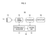
- FIG. 3 is a block diagram illustrating a structure of an ultrasound system constructed in accordance with one embodiment of the present invention
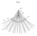
- Fig. 4 is an exemplary diagram for illustrating setting steering angles of scan lines in accordance with one embodiment of the present invention.
- Fig. 5 is an exemplary diagram for illustrating setting steering angles of scan lines in accordance with another embodiment of the present invention.
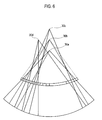
- Fig. 6 is an exemplary diagram for illustrating setting steering angles of scan lines in accordance with yet another embodiment of the present invention.
- an ultrasound system comprising a probe, a scan line setting unit and a control unit.
- the probe includes a plurality of transducer elements, which convert electrical signals into ultrasound signals for transmission along scan lines to an object and further convert the received ultrasound signals reflected from the object into electrical signals.
- the scan line setting unit may set a common point at which the scan lines for the transducer elements intersect.
- the scan line setting unit may further set a plurality of virtual common points based on the common point.
- the scan line setting unit may also set a steering angle of each of the scan lines for the transducer elements in accordance with the plurality of virtual common points.
- the control unit may be programmed to control the steering of each of the scan lines for the transducer elements based on the respective steering angle.
- FIGS. 3 to 6 Detailed descriptions for the embodiments of the present invention may be provided with reference to accompanying FIGS. 3 to 6.
- an ultrasound system 100 constructed in accordance with one embodiment of the present invention comprises a probe 110, a scan line setting unit 120, a beam former 130, a processor 140 and a display unit 150.
- the probe 110 includes a transducer array 112 comprising a plurality of transducer elements.
- the probe 110 may be configured to transmit ultrasound signals along the scan lines to an object and receive the ultrasound signals that are reflected from the object.
- the probe 110 may include a curved probe and a linear probe.
- the scan line setting unit 120 may include a steering angle calculator 121 and a control unit 122, as shown in FIG. 3.
- the steering angle calculator 121 may be configured to set a plurality of virtual common points based on the common point at which the scan lines of the transducer elements intersect.
- the steering angle calculator 121 may be further configured to calculate the steering angle of each of the scan lines for the transducer elements in accordance with the plurality of virtual points as set. As such, intervals between the scan lines for the transducer elements located at both ends of the transducer array 112 become wider and those for transducer elements at the center of the transducer array 112 become narrower.
- the steering angle calculator 121 may be configured to set a plurality of virtual common points based on the common point.
- the steering angle calculator 121 may then divide a plurality of transducer elements into a prescribed number of groups in accordance with the number of the virtual common points as set.
- the steering angle calculator 121 may be further configured to calculate the steering angle of each of the scan lines for the transducer elements using the virtual common point corresponding to the group to which the transducer belongs.
- the steering angle calculator 121 may be configured to set the first virtual common point 30a by moving the common point 30 toward the transducer array 112 and the second virtual common point 30b by moving the common point 30 away from the transducer array 112 based on the common point 30.
- the common point 30 is the point at which all scan lines 210 of the transducer elements intersect.
- the steering angle calculator 121 may be further configured to divide a plurality of transducer elements into two groups in accordance with the two virtual common points, which are set by the steering angle calculator 121.
- the steering angle calculator 121 may set the first transducer element group ⁇ T 1 , T 3 , T 5 , T 7 , ... ⁇ and the second transducer element group ⁇ T 2 , T 4 , T 6 , T 8 , ... ⁇ from a plurality of transducer elements ⁇ T 1 , T 2 , T 3 , T 4 , ..., T n . ⁇ .
- the steering angle calculator 121 may also set the first virtual common point 30a corresponding to the first transducer element group and the second virtual common point 30b corresponding to the second transducer element group in order to calculate the steering angle for each of the scan line of the transducer elements.
- the scan lines corresponding to the first transducer element group indicated by 221 may be formed in a radial shape with the center of the virtual common point 30a.
- the scan lines corresponding to the second transducer element group indicated by 222 may be also formed in a radial shape with the center of the virtual common point 30b.
- the steering angle calculator may be configured to set four virtual common points 30a-30d.
- the steering angle calculator may then set the first transducer element group ⁇ T 1 , T 5 , T 9 , T 13 , ... ⁇ , the second transducer element group ⁇ T 2 , T 6 , T 10 , T 14 , ... ⁇ , the third transducer element group ⁇ T 3 , T 7 , T 11 , T 15 , ... ⁇ and the fourth transducer element group ⁇ T 4 , T 8 , T 12 , T 16 , ... ⁇ from a plurality of transducer elements ⁇ T 1 , T 2 , T 3 , T 4 , ..., T n . ⁇ .
- the steering angle calculator may be also configured to allocate four virtual common points to the transducer element groups.
- the present invention is certainly not limited thereto.
- the number of virtual common points can be N.
- the first transducer element group, ⁇ T 1 , T N+1 , T 2N+ , T 3N+1 , ... ⁇ and the second transducer element group, ⁇ T 2 , T N+2 , T 2N+2 , T 3N+2, ... ⁇ may be set from (T 1 , T 2 , T 3 , T 4 , ..., T n . ⁇ .
- the transducer element groups may be also set up to the Nth transducer element group, ⁇ T N , T 2N , T 3N , T 4N , ... ⁇ .
- a plurality of virtual common points is described to be set by moving the common point in the perpendicular direction to the transducer array 112.
- the present invention is certainly not limited to the embodiments described above.
- a plurality of virtual common points can be set by moving the common point not only in the perpendicular direction, but also in the horizontal direction, diagonal direction, etc., as shown in Fig. 6.
- the control unit 122 may be configured to control the operations of the beam former 130 and the processor 140 based on the steering angles, which are calculated from the steering angle calculator 121.
- the control unit 122 may be further configured to control the beam former 130 to transmit/receive the ultrasound signals along scan lines 221, 222, which are steered with the associated steering angles.
- the control unit 122 may be further configured to control the processor 140 for forming ultrasound images from signals outputted from the beam former 130 based on the information of the scan lines.
- the beam former 130 may be adapted to transmit-focus ultrasound signals to the object along scan lines 221, 222 through the transducer elements 112 of the probe 110 under the control of the control unit 122.
- the beam former 130 may be configured to apply a time-delay to ultrasound signals and receive-focus ultrasound signals reflected from the object and received at the transducer elements.
- the processor 140 may be programmed to form an ultrasound image of the object from the signals, which are outputted from the beam former 130 based on scan line information under the control of the control unit 122.
- the display unit 150 may display the ultrasound image received from the processor 140.
- Embodiments of the present invention may provide an ultrasound system and method for controlling scan lines.
- the ultrasound system may calculate the steering angle of each of the scan lines for the transducer elements based on a plurality of the virtual common points.
- the ultrasound system may also provide ultrasound images having a wide view angle without deteriorating the qualities of ultrasound images.
- an ultrasound system comprising : a probe including a plurality of transducer elements to transmit ultrasound signals along scan lines to an object, receive ultrasound signals reflected from the object, and convert the received ultrasound signals into electrical signals, said scan lines being associated with the respective transducer elements; a scan line setting unit to set a common point at which the scan lines for the transducer elements intersect, set a plurality of virtual common points based on the set common point, and set a steering angle of each of the scan lines in accordance with the plurality of the virtual common points; and a control unit to control the steering of each of the scan lines based on the respective steering angle.
- a method of controlling scan lines in an ultrasound system including a plurality of transducer elements to transmit and receive ultrasound signals along the scan lines, the method comprising: a) setting a plurality of virtual common points based on a common point at which the scan lines for the transducer elements intersect; b) setting a steering angle of each of the scan lines for the transducer elements in accordance with the respective virtual common point as set; and c) controlling the steering of each of the scan lines for the transducer elements based on the respective steering angle.
- any reference in this specification to "one embodiment,” “an embodiment,” “example embodiment,” etc. means that a particular feature, structure or characteristic described in connection with the embodiment is included in at least one embodiment of the present invention.
- the appearances of such phrases in various places in the specification are not necessarily all referring to the same embodiment.
Landscapes
- Engineering & Computer Science (AREA)
- Physics & Mathematics (AREA)
- Radar, Positioning & Navigation (AREA)
- Remote Sensing (AREA)
- Acoustics & Sound (AREA)
- General Physics & Mathematics (AREA)
- Computer Networks & Wireless Communication (AREA)
- Health & Medical Sciences (AREA)
- Life Sciences & Earth Sciences (AREA)
- General Health & Medical Sciences (AREA)
- Pathology (AREA)
- Biomedical Technology (AREA)
- Medical Informatics (AREA)
- Immunology (AREA)
- Biochemistry (AREA)
- Biophysics (AREA)
- Nuclear Medicine, Radiotherapy & Molecular Imaging (AREA)
- Chemical & Material Sciences (AREA)
- Radiology & Medical Imaging (AREA)
- Heart & Thoracic Surgery (AREA)
- Analytical Chemistry (AREA)
- Molecular Biology (AREA)
- Surgery (AREA)
- Animal Behavior & Ethology (AREA)
- Public Health (AREA)
- Veterinary Medicine (AREA)
- Ultra Sonic Daignosis Equipment (AREA)
Abstract
Description
- The present application claims priority from
Korean Patent Application No. 10-2006-0086885 filed on September 8, 2006 - The present invention generally relates to an ultrasound system, and more particularly to an ultrasound system and method for controlling scan lines.
- An ultrasound system has become an important and popular diagnostic tool since it has a wide range of applications. Specifically, due to its non-invasive and nondestructive nature, the ultrasound system has been extensively used in the medical profession. Modem high-performance ultrasound systems and techniques are commonly used to produce two or three-dimensional diagnostic images of internal features of an object (e.g., human organs).
- Conventionally, probes of an ultrasound system include a transducer elements to transmit and receive ultrasound signals having a wide bandwidth. When transducer elements are electrically excited, ultrasounds signals are generated and transmitted to an object. Ultrasound echo signals that are reflected from the object and delivered to the transducer elements are converted into electrical signals. The converted electrical signals are amplified and processed to generate ultrasound image data.
- Specifically, an ultrasound system uses a curved linear probe to transmit and receive ultrasound signals. The curved linear probe transmits ultrasound signals in a radial shape such that an ultrasound image of an area, which is wider than the length of the probe, can be obtained. Fig. 1 is a geometrical diagram of scan lines for the transducer elements in a curved linear probe. As shown in Fig. 1, if each of the
scan lines 21 is extended to the back of thetransducer array 12, then a point ("common point") 30 at which all scan lines intersect is formed in accordance with the curvature of the surface of thetransducer array 12. If thecommon point 30 is moved to the probe as indicated by an arrow shown in Fig. 2, then a steering angle at which eachscan line 21 is steered is determined andnew scan lines 22 are formed with respect to the determined steering angles to obtain an ultrasound image having a wide view angle. - However, in conventional ultrasound systems, as the location of the common point is changed, intervals between scan lines become wider and qualities of ultrasound images are deteriorated. The conventional systems also have a problem in that the image quality of an object located in the center of an ultrasound image is deteriorated when the location of the common point is changed.
- Arrangements and embodiments may be described in detail with reference to the following drawings in which like reference numerals refer to like elements and wherein:
- FIG. 1 is a geometrical diagram of scan lines for a transducer in a curved linear probe;
- FIG. 2 is a geometrical diagram of scan lines for a transducer in a curved linear probe whose steering angles are adjusted;
- FIG. 3 is a block diagram illustrating a structure of an ultrasound system constructed in accordance with one embodiment of the present invention;
- Fig. 4 is an exemplary diagram for illustrating setting steering angles of scan lines in accordance with one embodiment of the present invention;
- Fig. 5 is an exemplary diagram for illustrating setting steering angles of scan lines in accordance with another embodiment of the present invention; and
- Fig. 6 is an exemplary diagram for illustrating setting steering angles of scan lines in accordance with yet another embodiment of the present invention.
- In accordance with a preferred embodiment of the present invention, there is provided an ultrasound system comprising a probe, a scan line setting unit and a control unit. The probe includes a plurality of transducer elements, which convert electrical signals into ultrasound signals for transmission along scan lines to an object and further convert the received ultrasound signals reflected from the object into electrical signals. The scan line setting unit may set a common point at which the scan lines for the transducer elements intersect. The scan line setting unit may further set a plurality of virtual common points based on the common point. The scan line setting unit may also set a steering angle of each of the scan lines for the transducer elements in accordance with the plurality of virtual common points. The control unit may be programmed to control the steering of each of the scan lines for the transducer elements based on the respective steering angle.
- Detailed descriptions for the embodiments of the present invention may be provided with reference to accompanying FIGS. 3 to 6.
- As shown in FIG. 3, an
ultrasound system 100 constructed in accordance with one embodiment of the present invention comprises aprobe 110, a scanline setting unit 120, a beam former 130, aprocessor 140 and adisplay unit 150. - The
probe 110 includes atransducer array 112 comprising a plurality of transducer elements. Theprobe 110 may be configured to transmit ultrasound signals along the scan lines to an object and receive the ultrasound signals that are reflected from the object. In accordance with one embodiment of the present invention, theprobe 110 may include a curved probe and a linear probe. - The scan
line setting unit 120 may include asteering angle calculator 121 and acontrol unit 122, as shown in FIG. 3. - The
steering angle calculator 121 may be configured to set a plurality of virtual common points based on the common point at which the scan lines of the transducer elements intersect. Thesteering angle calculator 121 may be further configured to calculate the steering angle of each of the scan lines for the transducer elements in accordance with the plurality of virtual points as set. As such, intervals between the scan lines for the transducer elements located at both ends of thetransducer array 112 become wider and those for transducer elements at the center of thetransducer array 112 become narrower. Thesteering angle calculator 121 may be configured to set a plurality of virtual common points based on the common point. Thesteering angle calculator 121 may then divide a plurality of transducer elements into a prescribed number of groups in accordance with the number of the virtual common points as set. Thesteering angle calculator 121 may be further configured to calculate the steering angle of each of the scan lines for the transducer elements using the virtual common point corresponding to the group to which the transducer belongs. - In accordance with one embodiment of the present invention, as shown in Fig. 4, the
steering angle calculator 121 may be configured to set the first virtualcommon point 30a by moving thecommon point 30 toward thetransducer array 112 and the second virtualcommon point 30b by moving thecommon point 30 away from thetransducer array 112 based on thecommon point 30. Thecommon point 30 is the point at which allscan lines 210 of the transducer elements intersect. Thesteering angle calculator 121 may be further configured to divide a plurality of transducer elements into two groups in accordance with the two virtual common points, which are set by thesteering angle calculator 121. That is, if two virtual common points are set, then thesteering angle calculator 121 may set the first transducer element group {T1, T3, T5, T7, ...} and the second transducer element group {T2, T4, T6, T8, ...} from a plurality of transducer elements {T1, T2, T3, T4, ..., Tn.}. Thesteering angle calculator 121 may also set the first virtualcommon point 30a corresponding to the first transducer element group and the second virtualcommon point 30b corresponding to the second transducer element group in order to calculate the steering angle for each of the scan line of the transducer elements. The scan lines corresponding to the first transducer element group indicated by 221 may be formed in a radial shape with the center of the virtualcommon point 30a. The scan lines corresponding to the second transducer element group indicated by 222 may be also formed in a radial shape with the center of the virtualcommon point 30b. - In accordance with another embodiment of the present invention, the steering angle calculator may be configured to set four virtual
common points 30a-30d. The steering angle calculator may then set the first transducer element group {T1, T5, T9, T13, ...}, the second transducer element group {T2, T6, T10, T14, ...}, the third transducer element group {T3, T7, T11, T15, ...} and the fourth transducer element group {T4, T8, T12, T16, ...} from a plurality of transducer elements {T1, T2, T3, T4, ..., Tn.}. The steering angle calculator may be also configured to allocate four virtual common points to the transducer element groups. - While above embodiments have been explained with 2 or 4 virtual common points, it should be noted that the present invention is certainly not limited thereto. The number of virtual common points can be N. In accordance with the N virtual common points, the first transducer element group, {T1, TN+1, T2N+, T3N+1, ...} and the second transducer element group, {T2, TN+2, T2N+2, T3N+2,...} may be set from (T1, T2, T3, T4, ..., Tn.}. Similarly, up to the Nth transducer element group, {TN, T2N, T3N, T4N, ...}, the transducer element groups may be also set.
- Furthermore, in the embodiments described above, a plurality of virtual common points is described to be set by moving the common point in the perpendicular direction to the
transducer array 112. However, the present invention is certainly not limited to the embodiments described above. Further, a plurality of virtual common points can be set by moving the common point not only in the perpendicular direction, but also in the horizontal direction, diagonal direction, etc., as shown in Fig. 6. - The
control unit 122 may be configured to control the operations of the beam former 130 and theprocessor 140 based on the steering angles, which are calculated from thesteering angle calculator 121. Thecontrol unit 122 may be further configured to control the beam former 130 to transmit/receive the ultrasound signals alongscan lines control unit 122 may be further configured to control theprocessor 140 for forming ultrasound images from signals outputted from the beam former 130 based on the information of the scan lines. - The beam former 130 may be adapted to transmit-focus ultrasound signals to the object along
scan lines transducer elements 112 of theprobe 110 under the control of thecontrol unit 122. The beam former 130 may be configured to apply a time-delay to ultrasound signals and receive-focus ultrasound signals reflected from the object and received at the transducer elements. - The
processor 140 may be programmed to form an ultrasound image of the object from the signals, which are outputted from the beam former 130 based on scan line information under the control of thecontrol unit 122. - The
display unit 150 may display the ultrasound image received from theprocessor 140. - Embodiments of the present invention may provide an ultrasound system and method for controlling scan lines. The ultrasound system may calculate the steering angle of each of the scan lines for the transducer elements based on a plurality of the virtual common points. The ultrasound system may also provide ultrasound images having a wide view angle without deteriorating the qualities of ultrasound images.
- In accordance with one embodiment of the present invention, there is provided an ultrasound system, comprising : a probe including a plurality of transducer elements to transmit ultrasound signals along scan lines to an object, receive ultrasound signals reflected from the object, and convert the received ultrasound signals into electrical signals, said scan lines being associated with the respective transducer elements; a scan line setting unit to set a common point at which the scan lines for the transducer elements intersect, set a plurality of virtual common points based on the set common point, and set a steering angle of each of the scan lines in accordance with the plurality of the virtual common points; and a control unit to control the steering of each of the scan lines based on the respective steering angle.
Furthermore, in accordance with another embodiment of the present invention, there is provided a method of controlling scan lines in an ultrasound system including a plurality of transducer elements to transmit and receive ultrasound signals along the scan lines, the method comprising: a) setting a plurality of virtual common points based on a common point at which the scan lines for the transducer elements intersect; b) setting a steering angle of each of the scan lines for the transducer elements in accordance with the respective virtual common point as set; and c) controlling the steering of each of the scan lines for the transducer elements based on the respective steering angle. - Any reference in this specification to "one embodiment," "an embodiment," "example embodiment," etc., means that a particular feature, structure or characteristic described in connection with the embodiment is included in at least one embodiment of the present invention. The appearances of such phrases in various places in the specification are not necessarily all referring to the same embodiment. Further, when a particular feature, structure or characteristic is described in connection with any embodiment, it is submitted that it is within the purview of one skilled in the art to affect such feature, structure or characteristic in connection with other ones of the embodiments.
- Although embodiments have been described with reference to a number of illustrative embodiments thereof, it should be understood that numerous other modifications and embodiments can be devised by those skilled in the art that will fall within the spirit and scope of the principles of this disclosure. More particularly, numerous variations and modifications are possible in the component parts and/or arrangements of the subject combination arrangement within the scope of the disclosure, the drawings and the appended claims. In addition to variations and modifications in the component parts and/or arrangements, alternative uses will also be apparent to those skilled in the art.
Claims (4)
- An ultrasound system, comprising:a probe including a plurality of transducer elements to transmit ultrasound signals along scan lines to an object and receive the ultrasound signals reflected from the object, the transducer elements further being configured to convert the received ultrasound signals into electrical signals, wherein said scan lines are associated with the respective transducer elements ;a scan line setting unit to set a common point at which the scan lines for the transducer elements intersect and set a plurality of virtual common points based on the set common point, the scan line setting unit further being configured to set a steering angle of each of the scan lines in accordance with the plurality of the virtual common points; anda control unit to control the steering of each of the scan lines based on the respective steering angle.
- The ultrasound system of Claim 1, wherein the scan line setting unit includes a means to divide the plurality of transducer elements into a prescribed number of groups based on the plurality of virtual common points and set the virtual common points corresponding to the respective groups, the scan line setting unit further being configured to calculate the steering angle of each of the scan lines for the transducer elements.
- A method of controlling scan lines in an ultrasound system including a plurality of transducer elements to transmit and receive ultrasound signals along the scan lines, the method comprising:a) setting a plurality of virtual common points based on a common point at which the scan lines for the transducer elements intersect;b) setting a steering angle of each of the scan lines for the transducer elements in accordance with the respective virtual common point as set; andc) controlling the steering of each of the scan lines for the transducer elements based on the respective steering angle.
- The method of Claim 3, wherein the step b) comprises:b1) dividing the plurality of transducer elements into a prescribed number of groups based on the plurality of virtual common points;b2) setting the virtual common points corresponding to the respective groups; andb3) calculating the steering angle of each of the scan lines for the transducer elements.
Applications Claiming Priority (1)
| Application Number | Priority Date | Filing Date | Title |
|---|---|---|---|
| KR1020060086885A KR100949066B1 (en) | 2006-09-08 | 2006-09-08 | Ultrasound system and method for controlling scan lines |
Publications (2)
| Publication Number | Publication Date |
|---|---|
| EP1898233A1 true EP1898233A1 (en) | 2008-03-12 |
| EP1898233B1 EP1898233B1 (en) | 2011-08-17 |
Family
ID=38705093
Family Applications (1)
| Application Number | Title | Priority Date | Filing Date |
|---|---|---|---|
| EP07016327A Active EP1898233B1 (en) | 2006-09-08 | 2007-08-21 | Ultrasound system and method for controlling scan lines |
Country Status (4)
| Country | Link |
|---|---|
| US (1) | US20080064958A1 (en) |
| EP (1) | EP1898233B1 (en) |
| JP (1) | JP2008062050A (en) |
| KR (1) | KR100949066B1 (en) |
Cited By (1)
| Publication number | Priority date | Publication date | Assignee | Title |
|---|---|---|---|---|
| JP2012086007A (en) * | 2010-10-19 | 2012-05-10 | Samsung Medison Co Ltd | Ultrasonic system and method for providing ultrasonic space combined video based on central line of ultrasonic image ultrasonic image |
Families Citing this family (4)
| Publication number | Priority date | Publication date | Assignee | Title |
|---|---|---|---|---|
| KR100978479B1 (en) * | 2008-11-03 | 2010-08-30 | 주식회사 메디슨 | Ultrasound system and method for performing scan conversion at high speed |
| KR101175402B1 (en) * | 2009-08-31 | 2012-08-20 | 삼성메디슨 주식회사 | Ultrasound system and method for setting steering of scanlines based on virtual transducer element |
| CN109975814B (en) * | 2017-12-28 | 2020-09-22 | 深圳先进技术研究院 | Ultrasound imaging method, system and device |
| JP7211150B2 (en) * | 2019-02-21 | 2023-01-24 | コニカミノルタ株式会社 | ULTRASOUND DIAGNOSTIC DEVICE, ULTRASOUND IMAGE GENERATING METHOD AND PROGRAM |
Citations (3)
| Publication number | Priority date | Publication date | Assignee | Title |
|---|---|---|---|---|
| US5235986A (en) * | 1990-02-12 | 1993-08-17 | Acuson Corporation | Variable origin-variable angle acoustic scanning method and apparatus for a curved linear array |
| US5261408A (en) * | 1990-02-12 | 1993-11-16 | Acuson Corporation | Variable origin-variable acoustic scanning method and apparatus |
| US20030018264A1 (en) * | 2001-06-19 | 2003-01-23 | Yoichi Suzuki | Ultrasonic imaging apparatus |
Family Cites Families (4)
| Publication number | Priority date | Publication date | Assignee | Title |
|---|---|---|---|---|
| US5148810A (en) * | 1990-02-12 | 1992-09-22 | Acuson Corporation | Variable origin-variable angle acoustic scanning method and apparatus |
| US6880554B1 (en) * | 1992-12-22 | 2005-04-19 | Battelle Memorial Institute | Dispensing device |
| KR100432617B1 (en) | 2001-05-16 | 2004-05-22 | 주식회사 메디슨 | Apparatus and method for forming ultrasound images using a set of golay codes with orthogonal property |
| US6709395B2 (en) * | 2002-06-25 | 2004-03-23 | Koninklijke Philips Electronics N.V. | System and method for electronically altering ultrasound scan line origin for a three-dimensional ultrasound system |
-
2006
- 2006-09-08 KR KR1020060086885A patent/KR100949066B1/en active Active
-
2007
- 2007-08-21 EP EP07016327A patent/EP1898233B1/en active Active
- 2007-08-22 JP JP2007215702A patent/JP2008062050A/en active Pending
- 2007-08-23 US US11/844,026 patent/US20080064958A1/en not_active Abandoned
Patent Citations (3)
| Publication number | Priority date | Publication date | Assignee | Title |
|---|---|---|---|---|
| US5235986A (en) * | 1990-02-12 | 1993-08-17 | Acuson Corporation | Variable origin-variable angle acoustic scanning method and apparatus for a curved linear array |
| US5261408A (en) * | 1990-02-12 | 1993-11-16 | Acuson Corporation | Variable origin-variable acoustic scanning method and apparatus |
| US20030018264A1 (en) * | 2001-06-19 | 2003-01-23 | Yoichi Suzuki | Ultrasonic imaging apparatus |
Cited By (2)
| Publication number | Priority date | Publication date | Assignee | Title |
|---|---|---|---|---|
| JP2012086007A (en) * | 2010-10-19 | 2012-05-10 | Samsung Medison Co Ltd | Ultrasonic system and method for providing ultrasonic space combined video based on central line of ultrasonic image ultrasonic image |
| US9151841B2 (en) | 2010-10-19 | 2015-10-06 | Samsung Medison Co., Ltd. | Providing an ultrasound spatial compound image based on center lines of ultrasound images in an ultrasound system |
Also Published As
| Publication number | Publication date |
|---|---|
| KR20080022978A (en) | 2008-03-12 |
| JP2008062050A (en) | 2008-03-21 |
| KR100949066B1 (en) | 2010-03-30 |
| EP1898233B1 (en) | 2011-08-17 |
| US20080064958A1 (en) | 2008-03-13 |
Similar Documents
| Publication | Publication Date | Title |
|---|---|---|
| EP1903353B1 (en) | Ultrasound system and method for forming ultrasound images | |
| US7927276B2 (en) | Apparatus and method for forming an ultrasound image | |
| US8506488B2 (en) | Ultrasound image enhancement in an ultrasound system | |
| EP1983355A1 (en) | Ultrasound probe having a transducer array with multiple radii of curvature | |
| EP2325672A1 (en) | Spatial compound imaging in an ultrasound system | |
| US20080063305A1 (en) | Apparatus and method for displaying an ultrasound image | |
| EP1914567B1 (en) | Apparatus and method for forming an ultrasound image | |
| US7789832B2 (en) | Ultrasound system and method for controlling steering angles of scan lines | |
| EP1898233B1 (en) | Ultrasound system and method for controlling scan lines | |
| US20190083064A1 (en) | Two dimensional ultrasonic array transducer with one dimensional patches | |
| ATE313143T1 (en) | TRANSDUCER ARRANGEMENT OF AN ULTRASONIC DIAGNOSTIC IMAGING SYSTEM WITH MULTIPLE LINE DIVISIONS | |
| US10304226B2 (en) | Ultrasound focal zone system and method | |
| EP2466330B1 (en) | Ultrasound system and method for processing beam-forming based on sampling data | |
| US9140790B2 (en) | Ultrasound system and method of forming ultrasound image | |
| CN110031554B (en) | Array element positioning method and device of flexible ultrasonic transducer and terminal | |
| CN112998745A (en) | Transmitting beam forming method and system for ultrasonic imaging and diagnostic equipment | |
| US20070167759A1 (en) | Ultrasound imaging system for displaying an original ultrasound image in a real size | |
| JP2784788B2 (en) | Ultrasound diagnostic equipment | |
| KR20230048892A (en) | Ultrasound imaging device using virtual receiving array and ultrasoudn imaging system including the same | |
| JPS5841535A (en) | Ultrasound diagnostic equipment | |
| JPH0337940B2 (en) |
Legal Events
| Date | Code | Title | Description |
|---|---|---|---|
| PUAI | Public reference made under article 153(3) epc to a published international application that has entered the european phase |
Free format text: ORIGINAL CODE: 0009012 |
|
| AK | Designated contracting states |
Kind code of ref document: A1 Designated state(s): AT BE BG CH CY CZ DE DK EE ES FI FR GB GR HU IE IS IT LI LT LU LV MC MT NL PL PT RO SE SI SK TR |
|
| AX | Request for extension of the european patent |
Extension state: AL BA HR MK YU |
|
| 17P | Request for examination filed |
Effective date: 20080613 |
|
| 17Q | First examination report despatched |
Effective date: 20080714 |
|
| AKX | Designation fees paid |
Designated state(s): DE FR IT |
|
| GRAP | Despatch of communication of intention to grant a patent |
Free format text: ORIGINAL CODE: EPIDOSNIGR1 |
|
| GRAS | Grant fee paid |
Free format text: ORIGINAL CODE: EPIDOSNIGR3 |
|
| GRAA | (expected) grant |
Free format text: ORIGINAL CODE: 0009210 |
|
| AK | Designated contracting states |
Kind code of ref document: B1 Designated state(s): DE FR IT |
|
| REG | Reference to a national code |
Ref country code: DE Ref legal event code: R096 Ref document number: 602007016528 Country of ref document: DE Effective date: 20111117 |
|
| PLBE | No opposition filed within time limit |
Free format text: ORIGINAL CODE: 0009261 |
|
| STAA | Information on the status of an ep patent application or granted ep patent |
Free format text: STATUS: NO OPPOSITION FILED WITHIN TIME LIMIT |
|
| 26N | No opposition filed |
Effective date: 20120521 |
|
| REG | Reference to a national code |
Ref country code: DE Ref legal event code: R097 Ref document number: 602007016528 Country of ref document: DE Effective date: 20120521 |
|
| REG | Reference to a national code |
Ref country code: FR Ref legal event code: PLFP Year of fee payment: 10 |
|
| REG | Reference to a national code |
Ref country code: FR Ref legal event code: PLFP Year of fee payment: 11 |
|
| REG | Reference to a national code |
Ref country code: FR Ref legal event code: PLFP Year of fee payment: 12 |
|
| PGFP | Annual fee paid to national office [announced via postgrant information from national office to epo] |
Ref country code: DE Payment date: 20250707 Year of fee payment: 19 |
|
| PGFP | Annual fee paid to national office [announced via postgrant information from national office to epo] |
Ref country code: IT Payment date: 20250710 Year of fee payment: 19 |
|
| PGFP | Annual fee paid to national office [announced via postgrant information from national office to epo] |
Ref country code: FR Payment date: 20250715 Year of fee payment: 19 |