EP1898232A1 - Method and system for collision avoidance - Google Patents
Method and system for collision avoidance Download PDFInfo
- Publication number
- EP1898232A1 EP1898232A1 EP07115990A EP07115990A EP1898232A1 EP 1898232 A1 EP1898232 A1 EP 1898232A1 EP 07115990 A EP07115990 A EP 07115990A EP 07115990 A EP07115990 A EP 07115990A EP 1898232 A1 EP1898232 A1 EP 1898232A1
- Authority
- EP
- European Patent Office
- Prior art keywords
- future
- host vehicle
- lane
- objects
- estimator
- Prior art date
- Legal status (The legal status is an assumption and is not a legal conclusion. Google has not performed a legal analysis and makes no representation as to the accuracy of the status listed.)
- Granted
Links
- 238000000034 method Methods 0.000 title claims abstract description 37
- 230000008859 change Effects 0.000 claims abstract description 17
- 230000001133 acceleration Effects 0.000 claims description 11
- 230000002265 prevention Effects 0.000 claims description 8
- 230000000694 effects Effects 0.000 claims description 6
- 230000008569 process Effects 0.000 claims description 4
- 230000009471 action Effects 0.000 description 7
- 238000005259 measurement Methods 0.000 description 7
- 241001465754 Metazoa Species 0.000 description 3
- 230000003993 interaction Effects 0.000 description 3
- 238000012614 Monte-Carlo sampling Methods 0.000 description 2
- 239000013598 vector Substances 0.000 description 2
- 241000478345 Afer Species 0.000 description 1
- 241000238631 Hexapoda Species 0.000 description 1
- 238000005516 engineering process Methods 0.000 description 1
- 239000011159 matrix material Substances 0.000 description 1
- 239000002184 metal Substances 0.000 description 1
- 238000012795 verification Methods 0.000 description 1
Images
Classifications
-
- G—PHYSICS
- G01—MEASURING; TESTING
- G01S—RADIO DIRECTION-FINDING; RADIO NAVIGATION; DETERMINING DISTANCE OR VELOCITY BY USE OF RADIO WAVES; LOCATING OR PRESENCE-DETECTING BY USE OF THE REFLECTION OR RERADIATION OF RADIO WAVES; ANALOGOUS ARRANGEMENTS USING OTHER WAVES
- G01S13/00—Systems using the reflection or reradiation of radio waves, e.g. radar systems; Analogous systems using reflection or reradiation of waves whose nature or wavelength is irrelevant or unspecified
- G01S13/86—Combinations of radar systems with non-radar systems, e.g. sonar, direction finder
- G01S13/867—Combination of radar systems with cameras
-
- B—PERFORMING OPERATIONS; TRANSPORTING
- B60—VEHICLES IN GENERAL
- B60W—CONJOINT CONTROL OF VEHICLE SUB-UNITS OF DIFFERENT TYPE OR DIFFERENT FUNCTION; CONTROL SYSTEMS SPECIALLY ADAPTED FOR HYBRID VEHICLES; ROAD VEHICLE DRIVE CONTROL SYSTEMS FOR PURPOSES NOT RELATED TO THE CONTROL OF A PARTICULAR SUB-UNIT
- B60W30/00—Purposes of road vehicle drive control systems not related to the control of a particular sub-unit, e.g. of systems using conjoint control of vehicle sub-units
- B60W30/08—Active safety systems predicting or avoiding probable or impending collision or attempting to minimise its consequences
- B60W30/09—Taking automatic action to avoid collision, e.g. braking and steering
-
- G—PHYSICS
- G01—MEASURING; TESTING
- G01S—RADIO DIRECTION-FINDING; RADIO NAVIGATION; DETERMINING DISTANCE OR VELOCITY BY USE OF RADIO WAVES; LOCATING OR PRESENCE-DETECTING BY USE OF THE REFLECTION OR RERADIATION OF RADIO WAVES; ANALOGOUS ARRANGEMENTS USING OTHER WAVES
- G01S13/00—Systems using the reflection or reradiation of radio waves, e.g. radar systems; Analogous systems using reflection or reradiation of waves whose nature or wavelength is irrelevant or unspecified
- G01S13/88—Radar or analogous systems specially adapted for specific applications
- G01S13/93—Radar or analogous systems specially adapted for specific applications for anti-collision purposes
- G01S13/931—Radar or analogous systems specially adapted for specific applications for anti-collision purposes of land vehicles
-
- G—PHYSICS
- G08—SIGNALLING
- G08G—TRAFFIC CONTROL SYSTEMS
- G08G1/00—Traffic control systems for road vehicles
- G08G1/16—Anti-collision systems
- G08G1/167—Driving aids for lane monitoring, lane changing, e.g. blind spot detection
-
- G—PHYSICS
- G01—MEASURING; TESTING
- G01S—RADIO DIRECTION-FINDING; RADIO NAVIGATION; DETERMINING DISTANCE OR VELOCITY BY USE OF RADIO WAVES; LOCATING OR PRESENCE-DETECTING BY USE OF THE REFLECTION OR RERADIATION OF RADIO WAVES; ANALOGOUS ARRANGEMENTS USING OTHER WAVES
- G01S13/00—Systems using the reflection or reradiation of radio waves, e.g. radar systems; Analogous systems using reflection or reradiation of waves whose nature or wavelength is irrelevant or unspecified
- G01S13/88—Radar or analogous systems specially adapted for specific applications
- G01S13/93—Radar or analogous systems specially adapted for specific applications for anti-collision purposes
- G01S13/931—Radar or analogous systems specially adapted for specific applications for anti-collision purposes of land vehicles
- G01S2013/932—Radar or analogous systems specially adapted for specific applications for anti-collision purposes of land vehicles using own vehicle data, e.g. ground speed, steering wheel direction
-
- G—PHYSICS
- G01—MEASURING; TESTING
- G01S—RADIO DIRECTION-FINDING; RADIO NAVIGATION; DETERMINING DISTANCE OR VELOCITY BY USE OF RADIO WAVES; LOCATING OR PRESENCE-DETECTING BY USE OF THE REFLECTION OR RERADIATION OF RADIO WAVES; ANALOGOUS ARRANGEMENTS USING OTHER WAVES
- G01S13/00—Systems using the reflection or reradiation of radio waves, e.g. radar systems; Analogous systems using reflection or reradiation of waves whose nature or wavelength is irrelevant or unspecified
- G01S13/88—Radar or analogous systems specially adapted for specific applications
- G01S13/93—Radar or analogous systems specially adapted for specific applications for anti-collision purposes
- G01S13/931—Radar or analogous systems specially adapted for specific applications for anti-collision purposes of land vehicles
- G01S2013/9327—Sensor installation details
- G01S2013/93271—Sensor installation details in the front of the vehicles
Definitions
- the invention relates to a method and an on board system for collision avoidance.
- Passive safety systems are directed toward reducing the effect of an accident, in the event an accident takes place while active safety systems are directed toward reducing the probability of occurrence of accidents.
- One type of active safety systems are collision avoidance systems relying on sensor technology for estimating a traffic situation. In this type of systems sensors are used to detect the presence of objects in a future trajectory of the vehicle. In the event the system detects that an object is within a future trajectory of the vehicle, normally a warning sign is produced to alert the driver.
- Systems that intercept the control of the vehicle, such as by braking the vehicle are also known.
- future trajectories of all detected object are estimated and compared with the future trajectory of the vehicle.
- a conflict event is detected.
- the future trajectories of the detected objects are based on position and velocity of the objects. Normally position and velocity are detected by use of sensors such as radars.
- sensors such as radars.
- object recognition based on input signals from cameras may be used.
- the future trajectory of the object is estimated primarily from input data relating to the position and velocity of the object in question.
- the future trajectory of the object may drastically change due to influence from other objects on the road.
- Monte Carlo Road Safety Reasoning Broadhurst, A., Baker, S., Kanade, T.
- the object of the invention is achieved by selecting an appropriate method of interception of vehicle control as a result of a detected risk for collision in between the host vehicle and an external object in a neighbouring lane into which the host vehicle makes an attempt to enter.
- the vehicle is thus not guided by an autopilot which would select a safest route freely.
- a torque in a direction to kept the vehicle in its current lane is applied only in certain identified cases, namely only when a threat, that is a conflicting event, is identified in a neighbouring lane.
- the torque is only applied in the case a conflicting event is identified in a neighbouring lane and no conflict is identified in the current lane.
- the torque may be of such a magnitude that the host vehicle is actually prevented from entering into the neighbouring lane, but is preferably of such a magnitude that a normal driver may overcome the applied torque and enter the neighbouring lane by applying a greater torque in the opposite direction.
- the torque will thus prevent a driver not being aware of the situation from entering into the neighbouring lane, but not prevent a driver that have judged that it is afer to enter intor the neighbouring lane anyhow.
- the method and system for collision avoidance according to the invention ensures that the driver has control over the host vehicle under most conditions while reducing the risk for collision under a well defined operation which is associated with increased risk, that is when a vehicle is about to leave a lane, either under the control of the driver or.
- the method described in the Broadhurst article in order to generate the future trajectories of external moving objects may be used.
- a generated future path will not be used to steer the host vehicle as suggested in the Broadhurst article.
- interception of host vehicle control will be performed as suggested in the characterising portion of claim 1, which will reduce the risk of collision in a specified situation associated with a high risk.
- the method step of estimating future trajectories of each external object, while considering influence by the future trajectories of the other external objects may include the following method step:
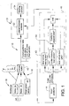
- FIG 1 a block scheme of a system 10 for collision avoidance is shown.
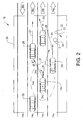
- Figure 2 shows an example of a traffic situation on a road 12.
- the road example 12 includes four lanes 14a - 14d, where lanes 14a - 14c are intended for traffic going in the direction from left to right as indicated by arrows 16a - 16c and the lane 16d is intended for traffic going in the direction from right to left as indicated by arrow 16d.
- the system 10 for collision avoidance 10 includes a sensor system 18 arranged on a host vehicle 20.
- the sensor system 18 is arranged to receive input data relating to a set of objects external 22, 24, 26, 28, 30, 32 of the host vehicle 20.
- the objects 22, 24, 26, 28, 30, 32 are positioned on the road 12 within a detecting range 34 of the sensor system 18. At least an object position (r, ⁇ and an object velocity ( ⁇ ) is associated with each object in said set of objects 22, 24, 26, 28, 30, 32.
- the set of object may include different type of objects such as obstacles 30, pedestrian or animals 32 and vehicles 22, 24, 26, 28.
- the vehicles 24, 26, 28 may be of different type and size, such as bikes, motorbikes, trucks and cars. Different types of objects may preferably be associated with different types of behaviour as will be explained in further detail below.
- Future trajectories 25,27,29, 33 are estimated in a future trajectory estimator, which will be explained in further detail below.
- the future trajectory will be estimated as no movement, that is a 0 vector indicated by reference number 0.
- a future trajectory of the host vehicle is denoted by arrow 21.
- the detecting range 34 of the sensor system 18 predominantly includes a region 34a in front of the vehicle, but may preferably also include a region 34b beside the vehicle and a region 34c behind the vehicle. As have been indicated in the figure, the region 34a in front of the vehicle is generally substantially larger than the region 34c behind the vehicle.
- the detecting range 34 preferably has some directivity so as to extend further in a main lobe having an angle with the heading direction of the vehicle in the interval between approximately ⁇ 30° than in directions outside the main lobe. It is suitable that the detecting range within the main lobe stretches at least 75 m, preferably at least 150 m and suitably approximately 300 m from the vehicle 20.
- the sensor system 18 preferably includes different types of sensors.
- the sensor system includes a vision type sensor 34, a radar 36 and a set of host vehicle sensors 38.
- the vision type sensor 36 preferably generates output data including distance to the object (r), direction to the object ( ⁇ ), distance to the right edge of the lane (L R ) of the host vehicle, distance to the left edge of the lane (L L ) of the host vehicle, curve radius (c 0 ) of the road at the current position of the host vehicle, heading direction ( ⁇ rel ) of the host vehicle relative to the lane and a classification of the object type.
- the classification of the object type may be based on image recognition of objects.
- the objects may be classified into obstacles 30, pedestrian or animals 32 and vehicles 24, 26, 28.
- the vehicles 24, 26, 28 may be of different type and size, such as bikes, motorbikes, trucks and cars.
- a vision sensor suitable for the collision avoidance system 10 is provided under the tradename Mobil Eye.
- the radar 36 provided output data including object position (r, ⁇ ), an object velocity ⁇ .
- the object velocity ( ⁇ ) is defined by a magnitude
- the host vehicle sensor preferably generates output data including host vehicle velocity (v), host vehicle yaw rate ( ⁇ abs ) and host vehicle steering angle ( ⁇ ). Host vehicle sensors capable of providing such output data are well known in the art.
- the output data 40 from the sensor system 18 are preferably treated by an object and road tracking block 42.
- the object and road tracking block may advantageously be a state estimator which estimates the states of all objects and the host vehicle and the road geometry.
- the states of the objects may include all data provided from the sensor system.
- the state estimator 42 is preferably arranged as a Kalman Filter based tracking system estimating at least the current object position (x i , y i ), the current object velocity (v i ), for all objects detected by the sensor system; the current host vehicle velocity (v) and the current host vehicle heading direction ( ⁇ rel ) and the road geometry such as curve radius (C 0 ) and lane width (W).
- the road tracking block is thus aware of the shape of the road and the position of the lanes ahead of the vehicle. From this information it may be decided whether the vehicle is about to leave the lane or not depending on whether the vehicle is about to exit its lane and enter into the neighbouring lane.
- the system may comprise a road geometry tracking unit which is arranged to determine the geometry of the road on which the vehicle is travelling and to express said geometry of the road as a curved coordinate system which follow the lane or lanes of said road, and in that said object position, object velocity and object direction of movement are expressed relative to said curved coordinate system.
- a road geometry tracking unit which is arranged to determine the geometry of the road on which the vehicle is travelling and to express said geometry of the road as a curved coordinate system which follow the lane or lanes of said road, and in that said object position, object velocity and object direction of movement are expressed relative to said curved coordinate system.
- a suitable state estimator for this purpose may be the state estimator described in " An Automotive Lane Guidance System", Andreas Eidehall, thesis 1122 at Link6ping University 2004 . In particular it is referred to the measurement equations 5.6a and 5.6b.
- a host 1 0 0 0 0 0 1 vT s v 2 ⁇ T s 2 / 2 v 3 ⁇ T s 3 / 6 0 0 1 vT s v 2 ⁇ T s 2 / 2 0 0 0 1 vT s 0 0 0 0 1
- a obj 1 T s 0 0 1 0 0 0 1
- A A host 0 0 I N ⁇
- the extended Kalman Filter will be provided with a feedback K t
- the output from the state estimator is used in a future trajectory estimator 44 which is arranged to estimate the future trajectory for each of the objects. According to the invention it is necessary that risk of conflicting events between individual objects in the set of objects detected by the sensor system 18 are assessed by the future trajectory estimator 44.
- Two general types of future trajectory estimators capable of including the mutual influence from external objects when estimating the future trajectory of an external object are known.
- This type of future trajectory estimator is disclosed in the Broadhurst article referred to above. The correction may be made to avoid the conflict event, or in the event this is not possible due to physical restraints such as available steering possibilities, surface friction, acceleration, etc, the correction is made to reduce the effect of the conflict event.
- future trajectory estimator In another type of future trajectory estimator, it is simply noted that a conflicting event occurs between two external objects. It is thereafter determined whether this conflict event will have an impact of the host vehicle or not. In both these systems the future trajectory estimator determines whether any of the future trajectories the external objects will mutually effect each other due to a risk of conflict in between the future trajectories of at least one pair of objects. In most known collision avoidance systems, interaction between the detected objects is not observed.
- the future trajectory estimator 44 is of the type described in the article " Monte Carlo Road Safety Reasoning", by Broadhurst et al. referred to above.
- each object type is assigned certain restrictions of movement. For instance obstacles will not move, pedestrians may move independently in the x and y directions, while cars are restricted to turn with a curvature radius restricted to possible steering angles.
- the future trajectory estimator first generates set of future trajectories for each object, which set of future trajectories may include all possible future control inputs selected from a set of typical human driver actions under consideration of the boundary conditions due to the restrictions of movement of the objects. These set of typical driver actions include stop, stop and turn, change lane, corner, overtake and random. For each possible future trajectory a certain risk is assigned.
- control input may be restricted to a selection of a plurality of values of one or more variables, wherein said values are selected within a predetermined interval.
- acceleration and steering angle are used as input variables.
- the trajectories that minimizes the risk for conflict between all future trajectories is selected as the most probable future trajectories.
- a Monte-Carlo sampling algorithm may suitable be selected.
- Figure 3 shows a flow scheme describing the operation of an embodiment of a future trajectory estimator 44.
- a plurality of objects having a position x i (t), a velocity v - i (t) and a class of input control signals u (t) .
- the input control signals may be of different types for different types of objects.
- the different types of objects may advantageously include obstacles, pedestrians and cars.
- a state update equation is defined for each c.
- L R sin ⁇ , where R equals the turning radius of the car.
- a plurality of future control input signals is associated with each object. For pedestrians, this amount to selection of a set of values of accelerations within a predetermined interval. For cars this amounts to selection of a set of values of accelerations and steering angles within predetermined intervals.
- a plurality of values are selected at each step in a plurality of discrete time steps together forming a prediction horizon. The selection may be performed by random or include a set of typical inputs defining typical manoeuvres such as corner, lane change, overtake and emergency stop. Preferably random input is combined with the typical inputs.
- a probability number is associated with each selected value.
- the probability number may be determined from a stored map describing the probability as a function of the input variable
- a future path is calculated by use of the selected values. A plurality of future paths is thus created for each object.
- a future trajectory is selected as one of the most probable future paths, preferably the most probable future path. This is done by calculating the aggregate probability value for the selected values at each step in a plurality of discrete time steps forming the prediction horizon. Future paths leading to conflicting events between objects may be removed in this sixth operational sequence, or in an operational sequence S6' prior to the sixth operational sequence.
- the operational sequences S1 - S6 may be performed in a future trajectory estimator 44 of the type described in the Broadhurst reference.
- the future trajectory estimator would then include first to sixth means for performing the first to sixth operational sequencies described above.
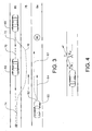
- figure 3 an example of a traffic situation which explains the importance of assigning also conflicting events between individual objects in the set of objects detected by the sensor system 18 and not only detect possible conflicting events between the future trajectories of the each set of objects with the future trajectory of the host vehicle.
- reference sign 60 denotes the host vehicle having a future trajectory which may be estimated by the current position of the host vehicle; the current heading 64 of the host vehicle; vehicle input data such as steering angle, acceleration; and road geometry.
- the traffic situation includes two external objects, a first vehicle 66 and a trailing vehicle 68. The velocity of the trailing vehicle is greater than the velocity of the first vehicle.
- the trailing vehicle has a first future trajectory 70 where the trailing vehicle 68 will follow the current heading 72 of the trailing vehicle. Since the velocity of the trailing vehicle 68 is greater than the velocity of the first vehicle, a conflict event exists between a future trajectory 74 of the first vehicle and the first future trajectory 70 of the trailing vehicle.
- future trajectory estimator 44 uses a future trajectory estimator 44 of the type described above, which future trajectory estimator 44 first generates a set of future trajectories for each object, which set of future trajectories includes all possible future control inputs selected from a set of typical human driver actions under consideration of the boundary conditions due to the restrictions of movement of the objects, also a second future trajectory 76 where the trailing vehicle 68 will avoid collision with the first vehicle 66 by passing the first vehicle 66 in the neighbouring lane 78 is generated by the future trajectory estimator 76. Since the risk for a conflicting event is smaller for the second future trajectory 76, than for the first future trajectory 70, the second future trajectory 76 is selected by the future trajectory estimator 44 as the most likely future trajectory.
- the future trajectory 76 of the trailing vehicle is a result from consideration of the interaction between future trajectories 70,74 of a pair of objects 66, 68 external to the host vehicle. Since conventional future trajectory detectors, which only compares the future trajectory of each external object with the future trajectory of the host vehicle would come to the conclusion that it is safe for the host vehicle 60 to enter the neighbouring lane 78 because the future trajectories of the external objects 70, 74, when no interaction between future trajectories of external objects is considered, would be maintained within the upper lane 80 in the traffic situation described in figure 3.
- the output from the future trajectory estimator 44 is entered into a lane exit control block 46.
- the lane exit control block 46 it is determined in a lane exit control block 46 whether the vehicle is about to exit the lane.
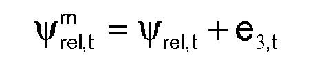
- the lane exit control block 46 verifies that the host vehicle is making an attempt to leave the lane based on the vertical distance ⁇ to the edge of the lane, the velocity v of the host vehicle and the heading angle ⁇ rel, relative to the road geometry.
- Figure 4 illustrates the parameters of the lane exit control block. When it is predicted that the host vehicle will leave the lane within shortly, the lane exit control block generates an affirmative output signal.
- the decision can be made for instance by comparing the predicted time or distance before the vehicle leaves the lane exceeds a threshold, which threshold may be fixed or depend on for instance the velocity of the vehicle.
- a threshold may be fixed or depend on for instance the velocity of the vehicle.
- a future conflict estimator control block 50 included in the lane exit control block it is determined if the future trajectory 82 of the host vehicle is involved in a conflicting event. Future trajectory 82 of the host vehicle is a future trajectory based on the verification of an attempt to leave the lower lane 84 in the traffic situation designed in figure 3.
- the future conflict estimator 50 furthermore verifies if the future conflict detected is within the neighbouring lane 78 into which the host vehicle makes an attempt to enter.
- the future conflict estimator 50 verifies a conflicting event and sends a control signal to a lane change prevention unit 51 including a lateral feedback controller 52 which generates a control signal to a steering actuator 54 of the vehicle.
- the lateral feedback controller applies a control signal to generate a torque in the direction, either so as to prevent the vehicle form changing lane or a smaller torque which may be overcome by the driver, which torque alerts the driver of the existence of a danger of entering the neighbouring lane, but does not prevent the driver from entering the neighbouring lane.
- the future conflict estimator control block 50 also determines if the current lane of the host vehicle is safe, that is if the a future trajectory 62 of the host vehicle within the current lower lane 84 does not include any conflicting events with external objects. If for instance an obstacle 86 is present in the current lane 84, the future conflict estimator control block 50 will not activate the lateral feedback controller 52 so as to either alert the driver or so as to prevent the driver of leaving the lane.
- the future trajectory estimator 44 is preferably, as have been described above, of the type described in the article "Monte Carlo Road Safety Reasoning" referred to above.
- the future trajectory estimator 44 is of a simpler type, which estimates the future trajectories in a feedback predictor (which may be of based on a Kalman filter) based on current velocity, heading angle and road geometry without generating a plurality of possible future trajectories for each object from which a most likely future trajectory may be selected by Monte Carlo sampling.
- a conflicting event will not be avoided by generating a more likely future trajectory for the object.
- the future conflict estimator control block may detect whether a conflicting event exist between a pair of objects in the heading direction of the host vehicle such that the future trajectory may be affected by this conflicting event.
- the conflicting event between the pair of external objects may not necessarily take place in the neighbouring lane 78 if this type of future trajectory estimator 44 is used since this type may not predict amended future trajectories of the external objects.
- the future trajectory estimator is arranged as a feed back controller, any change in the trajectory of the external objects will be detected by the sensor system 18 and will form basis for an updated prediction of the future trajectory of the external object. For this reason, this simpler type of future trajectory estimator may also generate accurate predictions of the future trajectories.
- the future conflict estimator control block may generate a control signal to the lateral feedback controller 52, either as a direct result or after verifying that no conflicting events exist in the current position of the host vehicle.
- the future conflict estimator control block would activate the lateral feedback controller 52 in the event a future conflict event between the host vehicle and an external object exists in a neighbouring lane.
- future trajectory estimator 44 may alternatively directly receive input signals from the sensor system without the use of the state estimator 42.
Landscapes
- Engineering & Computer Science (AREA)
- Radar, Positioning & Navigation (AREA)
- Remote Sensing (AREA)
- Physics & Mathematics (AREA)
- General Physics & Mathematics (AREA)
- Computer Networks & Wireless Communication (AREA)
- Electromagnetism (AREA)
- Automation & Control Theory (AREA)
- Transportation (AREA)
- Mechanical Engineering (AREA)
- Traffic Control Systems (AREA)
- Control Of Driving Devices And Active Controlling Of Vehicle (AREA)
Abstract
Preferably, the lane change is permitted if an obstacle is detected in the host vehicle's lane, allowing the driver to avoid said obstacle.
Description
- The invention relates to a method and an on board system for collision avoidance.
- In order to increase safety in traffic active as well as passive systems for further improving safety in traffic are continuously developed. Passive safety systems are directed toward reducing the effect of an accident, in the event an accident takes place while active safety systems are directed toward reducing the probability of occurrence of accidents. One type of active safety systems are collision avoidance systems relying on sensor technology for estimating a traffic situation. In this type of systems sensors are used to detect the presence of objects in a future trajectory of the vehicle. In the event the system detects that an object is within a future trajectory of the vehicle, normally a warning sign is produced to alert the driver. Systems that intercept the control of the vehicle, such as by braking the vehicle are also known.
- In most known collision avoidance systems and methods, future trajectories of all detected object are estimated and compared with the future trajectory of the vehicle. In the event the future trajectory of an object coincides with the future trajectory of the vehicle, a conflict event is detected. The future trajectories of the detected objects are based on position and velocity of the objects. Normally position and velocity are detected by use of sensors such as radars. In order to separate between large and small objects, between objects made of metal from concrete or animals object recognition based on input signals from cameras may be used. As soon as the velocity and position has been detected by the radar, and it has been verified that the detected object is a potentially dangerous object, and not for instance a flying insect or paper litter whirling round, the future trajectory of the object is estimated primarily from input data relating to the position and velocity of the object in question. However, the future trajectory of the object may drastically change due to influence from other objects on the road. In the article, "Monte Carlo Road Safety Reasoning", Broadhurst, A., Baker, S., Kanade, T. Monte Carlo road safety reasoning, Proceedings of the IEEE Intelligent Vehicles Symposium 2005, 6-8 June 2005, Page(s): 319 - 324, Las Vegas, Nevada, USA, a method is disclosed in which the future trajectory of an object is influenced by the traffic situation, that is by the future trajectories of other objects present on the road. The invention relates to a system and method for collision avoidance wherein the future trajectories of external objects are influenced by the traffic situation. In the Broadhurst article the following use of the system in the host vehicle is suggested: closed loop control of the vehicle for selecting the best predicted action, display of the best action to take in order to advice the driver, or display of warning signs for objects or unsafe regions of the road. However, in the event the control system suggested in this article is used to intercept in the control of the host vehicle by using the best predicted action for control of the host vehicle, the host vehicle will be run by an autopilot. Such solutions are generally not accepted for legal reasons and are furthermore mot appreciated by drivers. Even though the system and method described in, "Monte Carlo Road Safety Reasoning" has contributed with an important advance in object tracing and future path determination, there is still a need for improvements as regards the use of the information generated by the future trajectory estimator.
- It is an object of the invention to further reduce the risk for unsafe manoeuvres in a method or system for collision avoidance which estimates future trajectories of detected external objects
- It is particular an object of the invention to further reduce the risk for unsafe manoeuvres in a system where future trajectories of each external object are estimated while considering influence by the future trajectories of the other external objects.
- The object of the invention is achieved by selecting an appropriate method of interception of vehicle control as a result of a detected risk for collision in between the host vehicle and an external object in a neighbouring lane into which the host vehicle makes an attempt to enter. The vehicle is thus not guided by an autopilot which would select a safest route freely. In stead a torque in a direction to kept the vehicle in its current lane is applied only in certain identified cases, namely only when a threat, that is a conflicting event, is identified in a neighbouring lane. In a preferred embodiment, the torque is only applied in the case a conflicting event is identified in a neighbouring lane and no conflict is identified in the current lane.
- In a system or method according to the invention the following actions are taken estimating future trajectories of the external objects under consideration of the traffic situation, that is a future trajectory of an external object is influenced by the future trajectories of other external objects present on the road:
- determining, by use of a lane exit control block , whether the vehicle is is about to exit the lane;
- determining, by use of a future conflict estimator control block, if the future trajectory of the host vehicle is involved in a conflicting event in the neighbouring lane;
and - applying, by the use of a lane change prevention unit, a torque in the direction to keep the vehicle in its current lane in the event said future conflict estimator control block detects a conflict event of relevance for the host vehicle in the neighbouring lane into which the vehicle is about to enter.
- determining, by use of a future conflict estimator control block, if the future trajectory of the host vehicle is involved in a conflicting event in the neighbouring lane;
- The torque may be of such a magnitude that the host vehicle is actually prevented from entering into the neighbouring lane, but is preferably of such a magnitude that a normal driver may overcome the applied torque and enter the neighbouring lane by applying a greater torque in the opposite direction. The torque will thus prevent a driver not being aware of the situation from entering into the neighbouring lane, but not prevent a driver that have judged that it is afer to enter intor the neighbouring lane anyhow.
- The method and system for collision avoidance according to the invention ensures that the driver has control over the host vehicle under most conditions while reducing the risk for collision under a well defined operation which is associated with increased risk, that is when a vehicle is about to leave a lane, either under the control of the driver or.
- According to the invention the future trajectories for external objects are determined by the following method steps:
- receiving input data relating to a set of objects external to said host vehicle, said objects being positioned within a detecting range of said sensor system , wherein an object position (r,φ and an object velocity ṙ are associated with each object in said set of objects by a sensor system arranged on a host vehicle, said input data defining a current state of each object,
- associating a plurality of future control input signals with each moving object, where each future control signal will generate together with the current state of each moving object a separate future path in a state update equation,
- determining, by the use of a future trajectory estimator, future trajectories for each of the objects, by selecting one of the most probable future paths as the future trajectory,
- In an embodiment of the invention the method described in the Broadhurst article in order to generate the future trajectories of external moving objects may be used. However, a generated future path will not be used to steer the host vehicle as suggested in the Broadhurst article. Instead interception of host vehicle control will be performed as suggested in the characterising portion of claim 1, which will reduce the risk of collision in a specified situation associated with a high risk.
- In other embodiments of the invention the method step of estimating future trajectories of each external object, while considering influence by the future trajectories of the other external objects may include the following method step:
- determining whether any of future trajectories of external objects will mutually effect each other due to a risk of conflict in between the future trajectories of at least one pair of objects.
- An embodiment of the invention will be described in further detail below, with references to appended drawings where,
- Fig. 1
- shows a block scheme of a system for collision avoidance according to the invention,
- Fig. 2
- shows an example of a traffic situation on a road
- Fig. 3
- shows another example of a traffic situation on a road
- Fig. 4
- illustrates the parameters of the lane exit control block.
- An embodiment of the invention will be described below with references to figures 1 and 2. In figure 1 a block scheme of a system 10 for collision avoidance is shown. Figure 2 shows an example of a traffic situation on a
road 12. The road example 12 includes fourlanes 14a - 14d, wherelanes 14a - 14c are intended for traffic going in the direction from left to right as indicated byarrows 16a - 16c and thelane 16d is intended for traffic going in the direction from right to left as indicated byarrow 16d. The system 10 for collision avoidance 10 includes asensor system 18 arranged on a host vehicle 20.Thesensor system 18 is arranged to receive input data relating to a set of objects external 22, 24, 26, 28, 30, 32 of the host vehicle 20. Theobjects road 12 within a detectingrange 34 of thesensor system 18. At least an object position (r,φ and an object velocity (ṙ) is associated with each object in said set ofobjects obstacles 30, pedestrian oranimals 32 andvehicles vehicles -
Future trajectories obstacles 30, the future trajectory will be estimated as no movement, that is a 0 vector indicated byreference number 0. A future trajectory of the host vehicle is denoted byarrow 21. - The detecting
range 34 of thesensor system 18 predominantly includes a region 34a in front of the vehicle, but may preferably also include aregion 34b beside the vehicle and aregion 34c behind the vehicle. As have been indicated in the figure, the region 34a in front of the vehicle is generally substantially larger than theregion 34c behind the vehicle. The detectingrange 34 preferably has some directivity so as to extend further in a main lobe having an angle with the heading direction of the vehicle in the interval between approximately ± 30° than in directions outside the main lobe. It is suitable that the detecting range within the main lobe stretches at least 75 m, preferably at least 150 m and suitably approximately 300 m from the vehicle 20. - The
sensor system 18 preferably includes different types of sensors. In the embodiment shown in figure 1, the sensor system includes avision type sensor 34, aradar 36 and a set ofhost vehicle sensors 38. Thevision type sensor 36 preferably generates output data including distance to the object (r), direction to the object (Φ), distance to the right edge of the lane (LR) of the host vehicle, distance to the left edge of the lane (LL) of the host vehicle, curve radius (c0) of the road at the current position of the host vehicle, heading direction (ψrel) of the host vehicle relative to the lane and a classification of the object type. The classification of the object type may be based on image recognition of objects. The objects may be classified intoobstacles 30, pedestrian oranimals 32 andvehicles vehicles radar 36 provided output data including object position (r,Φ), an object velocity ṙ. The object velocity (ṙ) is defined by a magnitude |ṙ| and direction of movement (ṙ)/|ṙ| . The host vehicle sensor preferably generates output data including host vehicle velocity (v), host vehicle yaw rate (ψ̇abs) and host vehicle steering angle (θ). Host vehicle sensors capable of providing such output data are well known in the art. Theoutput data 40 from thesensor system 18 are preferably treated by an object androad tracking block 42. The object and road tracking block may advantageously be a state estimator which estimates the states of all objects and the host vehicle and the road geometry. The states of the objects may include all data provided from the sensor system. Thestate estimator 42 is preferably arranged as a Kalman Filter based tracking system estimating at least the current object position (xi, yi), the current object velocity (vi), for all objects detected by the sensor system; the current host vehicle velocity (v) and the current host vehicle heading direction (ψrel) and the road geometry such as curve radius (C0) and lane width (W). The road tracking block is thus aware of the shape of the road and the position of the lanes ahead of the vehicle. From this information it may be decided whether the vehicle is about to leave the lane or not depending on whether the vehicle is about to exit its lane and enter into the neighbouring lane. - For the purpose of tracking the external objects the system may comprise a road geometry tracking unit which is arranged to determine the geometry of the road on which the vehicle is travelling and to express said geometry of the road as a curved coordinate system which follow the lane or lanes of said road, and in that said object position, object velocity and object direction of movement are expressed relative to said curved coordinate system.
- A suitable state estimator for this purpose may be the state estimator described in "An Automotive Lane Guidance System", Andreas Eidehall, thesis 1122 at Link6ping University 2004. In particular it is referred to the measurement equations 5.6a and 5.6b.
- Expressed in the variables introduced above we have:


, where T transforms from a coordinate system x, y following the road geometry into a coordinate system (r, Φ) centred at the host vehicle. The variables (e1,....e6) are stochastic measurement noise. W represents the width of the lane. Superscripts m denotes measured quantities. yoff represents the distance from the middle of the lane. - Expressing the curve radius of the road as R = 1/c0+ c1x) and assuming ċ1 = 0 , the time continuous motion equations for the host vehicle states will be:


- Based on the model above an observer may be constructed using the following matrix definitions:


; where N is the number of objects, Ts is the sample time. Furthermore the following vectors are defined


Introducing
and the following process and measurement covariance matrices:
; where Qhost and Qobj are the process noise covariance matrices for the object states and Rhost and Robj are the measurement noise covariance matrices for the host and object measurement. - The measurement equations and motion equations can now be rewritten as

- A recursive one step predictor in the form of a Kalman filter will have the following appearance:

as an observer to the combined target geometry system

- The extended Kalman Filter will be provided with a feedback Kt
- The following equations are the extended Kalman Filter equations for a nonlinear measurement equation:


where
- Further details about the
state estimator 42 is provided in "An Automotive Lane Guidance System", Andreas Eidehall, thesis 1122 at Linköping University 2004. - The output from the state estimator is used in a
future trajectory estimator 44 which is arranged to estimate the future trajectory for each of the objects. According to the invention it is necessary that risk of conflicting events between individual objects in the set of objects detected by thesensor system 18 are assessed by thefuture trajectory estimator 44. Two general types of future trajectory estimators capable of including the mutual influence from external objects when estimating the future trajectory of an external object are known. A first type in which the future trajectory of an external object is corrected in a most likely fashion when a conflict event is detected. One example of this type of future trajectory estimator is disclosed in the Broadhurst article referred to above. The correction may be made to avoid the conflict event, or in the event this is not possible due to physical restraints such as available steering possibilities, surface friction, acceleration, etc, the correction is made to reduce the effect of the conflict event. - In another type of future trajectory estimator, it is simply noted that a conflicting event occurs between two external objects. It is thereafter determined whether this conflict event will have an impact of the host vehicle or not. In both these systems the future trajectory estimator determines whether any of the future trajectories the external objects will mutually effect each other due to a risk of conflict in between the future trajectories of at least one pair of objects. In most known collision avoidance systems, interaction between the detected objects is not observed.
- In most prior art systems normally only conflicting events between each object and the host vehicle are observed.
- In one embodiment of the invention the
future trajectory estimator 44 is of the type described in the article "Monte Carlo Road Safety Reasoning", by Broadhurst et al. referred to above. - In an embodiment of a
future trajectory estimator 44 of this type, each object type is assigned certain restrictions of movement. For instance obstacles will not move, pedestrians may move independently in the x and y directions, while cars are restricted to turn with a curvature radius restricted to possible steering angles. Starting with an initial state, which in one embodiment of the invention is determined by the object androad tracking block 42, the future trajectory estimator first generates set of future trajectories for each object, which set of future trajectories may include all possible future control inputs selected from a set of typical human driver actions under consideration of the boundary conditions due to the restrictions of movement of the objects. These set of typical driver actions include stop, stop and turn, change lane, corner, overtake and random. For each possible future trajectory a certain risk is assigned. Alternatively, the control input may be restricted to a selection of a plurality of values of one or more variables, wherein said values are selected within a predetermined interval. Preferably acceleration and steering angle are used as input variables. Among all possible future trajectories, the trajectories that minimizes the risk for conflict between all future trajectories is selected as the most probable future trajectories. In order to evaluate the probability of danger for all possible future trajectories, and thus find the future trajectories for the detected objects that has the minimal the risk for conflict between the trajectories a Monte-Carlo sampling algorithm may suitable be selected. - Figure 3 shows a flow scheme describing the operation of an embodiment of a
future trajectory estimator 44. - In a first operational sequence S1 a plurality of objects having a position
x i(t), a velocityv -i(t) and a class of input control signalsu (t) . The input control signals may be of different types for different types of objects. The different types of objects may advantageously include obstacles, pedestrians and cars. - In a second operational sequence S2 a state update equation is defined for each c. The state update equation may be described as
ṡ (t) = f(s (t),u (t). Obstacles will have a state update equationṡ (t) = 0 for the state
s (t)=[ x y θ ]. Pedestrians will have a state update equation [ṡ1 ṡ2 ṡ3 ṡ4]T = [s1 s2 u1 u2]T , where [u1u2]T = [axay]T, a denotes a random acceleration. The state is defined as [s1 s2 s3 s4]T = [x y ẋ ẏ]T. - Cars will have a state update equation [ṡ1 ṡ2 ṡ3 ṡ4]T = [s3 cos s4 s3 sin s4 u1 (s3 sinu2)/L]T, where
[u1u2]T = [a θ]T. a denotes acceleration and θ denotes steering angle. The state is defined as [s1 s2 s3 s4]T = [x y v ϕ]T, where v is the velocity and ϕ is the orientation. L = R sinθ, where R equals the turning radius of the car. - In a third operational sequence S3 a plurality of future control input signals is associated with each object. For pedestrians, this amount to selection of a set of values of accelerations within a predetermined interval. For cars this amounts to selection of a set of values of accelerations and steering angles within predetermined intervals. A plurality of values are selected at each step in a plurality of discrete time steps together forming a prediction horizon. The selection may be performed by random or include a set of typical inputs defining typical manoeuvres such as corner, lane change, overtake and emergency stop. Preferably random input is combined with the typical inputs.
- In a fourth operational sequence S4 a probability number is associated with each selected value. The probability number may be determined from a stored map describing the probability as a function of the input variable
- In a fifth operational sequence S5 a future path is calculated by use of the selected values. A plurality of future paths is thus created for each object.
- In a sixth operational sequence S6 a future trajectory is selected as one of the most probable future paths, preferably the most probable future path. This is done by calculating the aggregate probability value for the selected values at each step in a plurality of discrete time steps forming the prediction horizon. Future paths leading to conflicting events between objects may be removed in this sixth operational sequence, or in an operational sequence S6' prior to the sixth operational sequence.
- The operational sequences S1 - S6 may be performed in a
future trajectory estimator 44 of the type described in the Broadhurst reference. The future trajectory estimator would then include first to sixth means for performing the first to sixth operational sequencies described above. - In figure 3 an example of a traffic situation which explains the importance of assigning also conflicting events between individual objects in the set of objects detected by the
sensor system 18 and not only detect possible conflicting events between the future trajectories of the each set of objects with the future trajectory of the host vehicle. In figure 3reference sign 60 denotes the host vehicle having a future trajectory which may be estimated by the current position of the host vehicle; the current heading 64 of the host vehicle; vehicle input data such as steering angle, acceleration; and road geometry. The traffic situation includes two external objects, afirst vehicle 66 and a trailingvehicle 68. The velocity of the trailing vehicle is greater than the velocity of the first vehicle. At the current scenario, the trailing vehicle has a firstfuture trajectory 70 where the trailingvehicle 68 will follow the current heading 72 of the trailing vehicle. Since the velocity of the trailingvehicle 68 is greater than the velocity of the first vehicle, a conflict event exists between afuture trajectory 74 of the first vehicle and the firstfuture trajectory 70 of the trailing vehicle. However, using afuture trajectory estimator 44 of the type described above, whichfuture trajectory estimator 44 first generates a set of future trajectories for each object, which set of future trajectories includes all possible future control inputs selected from a set of typical human driver actions under consideration of the boundary conditions due to the restrictions of movement of the objects, also a secondfuture trajectory 76 where the trailingvehicle 68 will avoid collision with thefirst vehicle 66 by passing thefirst vehicle 66 in the neighbouringlane 78 is generated by thefuture trajectory estimator 76. Since the risk for a conflicting event is smaller for the secondfuture trajectory 76, than for the firstfuture trajectory 70, the secondfuture trajectory 76 is selected by thefuture trajectory estimator 44 as the most likely future trajectory. Thefuture trajectory 76 of the trailing vehicle is a result from consideration of the interaction betweenfuture trajectories objects host vehicle 60 to enter the neighbouringlane 78 because the future trajectories of theexternal objects upper lane 80 in the traffic situation described in figure 3. - According to the invention the output from the
future trajectory estimator 44 is entered into a laneexit control block 46. In the laneexit control block 46 it is determined in a laneexit control block 46 whether the vehicle is about to exit the lane. The laneexit control block 46 verifies that the host vehicle is making an attempt to leave the lane based on the vertical distance Δ to the edge of the lane, the velocity v of the host vehicle and the heading angle ψrel, relative to the road geometry. Figure 4 illustrates the parameters of the lane exit control block. When it is predicted that the host vehicle will leave the lane within shortly, the lane exit control block generates an affirmative output signal. The decision can be made for instance by comparing the predicted time or distance before the vehicle leaves the lane exceeds a threshold, which threshold may be fixed or depend on for instance the velocity of the vehicle. In a future conflictestimator control block 50 included in the lane exit control block it is determined if thefuture trajectory 82 of the host vehicle is involved in a conflicting event.Future trajectory 82 of the host vehicle is a future trajectory based on the verification of an attempt to leave thelower lane 84 in the traffic situation designed in figure 3. Thefuture conflict estimator 50 furthermore verifies if the future conflict detected is within the neighbouringlane 78 into which the host vehicle makes an attempt to enter. In one embodiment of the invention, thefuture conflict estimator 50 verifies a conflicting event and sends a control signal to a lanechange prevention unit 51 including alateral feedback controller 52 which generates a control signal to asteering actuator 54 of the vehicle. The lateral feedback controller applies a control signal to generate a torque in the direction, either so as to prevent the vehicle form changing lane or a smaller torque which may be overcome by the driver, which torque alerts the driver of the existence of a danger of entering the neighbouring lane, but does not prevent the driver from entering the neighbouring lane. - In a preferred embodiment the future conflict
estimator control block 50 also determines if the current lane of the host vehicle is safe, that is if the afuture trajectory 62 of the host vehicle within the currentlower lane 84 does not include any conflicting events with external objects. If for instance anobstacle 86 is present in thecurrent lane 84, the future conflictestimator control block 50 will not activate thelateral feedback controller 52 so as to either alert the driver or so as to prevent the driver of leaving the lane. - The
future trajectory estimator 44 is preferably, as have been described above, of the type described in the article "Monte Carlo Road Safety Reasoning" referred to above. Alternatively thefuture trajectory estimator 44 is of a simpler type, which estimates the future trajectories in a feedback predictor (which may be of based on a Kalman filter) based on current velocity, heading angle and road geometry without generating a plurality of possible future trajectories for each object from which a most likely future trajectory may be selected by Monte Carlo sampling. In this type of estimator, a conflicting event will not be avoided by generating a more likely future trajectory for the object. If this type of future trajectory estimator is used, the future conflict estimator control block may detect whether a conflicting event exist between a pair of objects in the heading direction of the host vehicle such that the future trajectory may be affected by this conflicting event. The conflicting event between the pair of external objects may not necessarily take place in the neighbouringlane 78 if this type offuture trajectory estimator 44 is used since this type may not predict amended future trajectories of the external objects. However, in the event the future trajectory estimator is arranged as a feed back controller, any change in the trajectory of the external objects will be detected by thesensor system 18 and will form basis for an updated prediction of the future trajectory of the external object. For this reason, this simpler type of future trajectory estimator may also generate accurate predictions of the future trajectories. Normally the judgement that the conflicting event may affect the host vehicle is only generated if the conflicting event between the external objects takes place in the neighbouring lane into which the host vehicle attempts to enter. In the event the conflicting event may affect the host vehicle the future conflict estimator control block may generate a control signal to thelateral feedback controller 52, either as a direct result or after verifying that no conflicting events exist in the current position of the host vehicle. Naturally the future conflict estimator control block would activate thelateral feedback controller 52 in the event a future conflict event between the host vehicle and an external object exists in a neighbouring lane. - Furthermore, the
future trajectory estimator 44 may alternatively directly receive input signals from the sensor system without the use of thestate estimator 42.
Claims (32)
- Method for collision avoidance for a host vehicle (20) comprising the following method steps:- receiving input data relating to a set of objects (22, 24, 26, 28, 30, 32) external to said host vehicle (20), said objects (22, 24, 26, 28, 30, 32) being positioned within a detecting range (34) of a sensor system (18) arranged on said host vehicle (20), wherein an object position (r,φ), and an object velocity (ṙ) are associated with each object (22, 24, 26, 28, 30, 32) in said set of objects (22, 24, 26, 28, 30, 32) by said sensor system (18), said input data defining a current state of each object,- estimating future trajectories of each external object, while considering influence by the future trajectories of the other external objects;- determining, by use of a lane exit control block (46), whether the host vehicle is about to exit a current lane where said host vehicle is currently positioned and enter into a neighbouring lane;- determining, by use of a future conflict estimator control block (50), if the future trajectory (21) of the host vehicle (20) is involved in a conflicting event in said neighbouring lane;- applying, by the use of a lane change prevention unit (51), a torque in the direction to keep the vehicle in said current lane in the event said future conflict estimator control block (50) detects a conflict event of relevance for the host vehicle in said neighbouring lane, characterised in that the method step of estimating future trajectories of each external object, while considering influence by the future trajectories of the other external objects includes the steps of:- associating a plurality of future control input signals with each moving object, where each future control signal will generate together with the current state of each moving object a separate future path in a state update equation,- determining, by the use of a future trajectory estimator (44), future trajectories (0,25,27,29,0,33) for each of the objects (22, 24, 26, 28, 30, 32), by selecting one of the most probable future paths as the future trajectory.
- A method according to claim 1, characterised in that, for each moving object, the most probable path is selected as the future trajectory.
- A method according to claim 1 or 2, characterised in that each of said future control input signals include a one or more dimensional variable.
- A method according to claim 3, characterised in that each of said future control input signal includes the variables acceleration (a) and steering angle (θ).
- A method according to claim 4, characterised in that each of said future control input signal is constituted by the variables acceleration (a) and steering angle (θ).
- A method according to any of claims 3 - 5, characterised in that said plurality of future paths for each moving object are generated by, at each step in a plurality of discrete time steps together forming a prediction horizon, selecting a plurality of values of each variable, wherein said values are selected within a predetermined interval.
- A method according to claim 6, characterised in that a probability number is associated with each value of the variable.
- A method according to claim 7, characterised in that an aggregate probability for each future path at the prediction horizon is calculated.
- A method according to any of claim 6 - 8, characterised in that said plurality of values of each variable are selected by random.
- A method according to any of claims 1 - 9, characterised in that any future path generating a conflicting event between the future trajectory paths of at least two objects, will be rejected as improbable future trajectory paths for the objects involved.
- A method according to any of claims 1 - 10, characterised in that in the event a future trajectory of the host vehicle in the current lane is involved in a conflicting event in said current lane, interception of the lane change prevention unit is prevented such that a torque will not be applied in a direction to keep said vehicle in said current lane even in the case where said future conflict estimator control block (50) detects a conflict event of relevance for the host vehicle in the neighbouring lane.
- A method according to claim 1, characterised in that said future trajectory estimator (44) determines whether any of these future trajectories (0,25,27,29,0,33) will mutually effect each other due to a risk of conflict in between the future trajectories of at least one pair of objects which is arranged to; and determines if the conflict event has an impact of the future trajectory of the host vehicle.
- A method according to any of claims 1-12, characterised in that said future conflict estimator control block (50) furthermore determines if a future trajectory of the host vehicle (20) in a current lane of the host vehicle includes any conflicting events with external objects and that said on board system for collision avoidance (10) only allows said lane change prevention unit (51) to prevent lane change if no conflicting events with external objects are detected in the current lane of the host vehicle (20).
- A method according to claim 12 or 13, characterised in that an object and road tracking block (42) processes output data (40) from the sensor system (18) in a state estimator which estimates the states of all external objects (22, 24, 26, 28, 30, 32), the host vehicle (20) and the road geometry.
- A method according to claim 12, 13 or 14, characterised in that said future trajectory estimator (44) corrects the future trajectory of an external object in order to avoid a conflict, when a conflict event between two external objects is detected.
- A method according to claim 12, 13 or 14, characterised in that said future trajectory estimator (44) determines the locus of the conflicting event and determines whether this conflict event will have an impact of the host vehicle or not.
- An on board system for collision avoidance (10) comprising- a sensor system (18) arranged on a host vehicle (20), said sensor system (18) being arranged to receive input data relating to a set of objects (22, 24, 26, 28, 30, 32) external to said host vehicle (20), said objects (22, 24, 26, 28, 30, 32) being positioned within a detecting range (34) of said sensor system (18), wherein an object position (r,Φ), and an object velocity (ṙ) are associated with each object (22, 24, 26, 28, 30, 32) in said set of objects (22, 24, 26, 28, 30, 32), said input data defining a current state of each object; and- a future trajectory estimator (44) arranged for estimating future trajectories of each external object, while considering influence by the future trajectories of the other external objects;- a lane exit control block (46) arranged do determine whether the host vehicle is about to exit a current lane where the host vehicle is currently positioned and enter into a neighbouring lane;- a future conflict estimator control block (50) arranged to determine if the future trajectory (21) of the host vehicle (20) is involved in a conflicting event;
and- a lane change prevention unit (51) arranged to apply a torque in a direction to keep the host vehicle in said current lane in the event said future conflict estimator control block (50) detects a conflict event of relevance for the host vehicle in the neighbouring lane into which the host vehicle is about to enter into, characterised in that said future trajectory estimator is arranged to estimate future trajectories of each external object, while considering influence by the future trajectories of the other external objects by:- associating a plurality of future control input signals with each moving object, where each future control signal will generate together with the current state of each moving object a separate future path in a state update equation,- determining, by the use of a future trajectory estimator (44), future trajectories (0,25,27,29,0,33) for each of the objects (22, 24, 26, 28, 30, 32), by selecting one of the most probable future paths as the future trajectory,. - An on board system for collision avoidance according to claim 17, characterised in that, for each moving object, the most probable path is selected as the future trajectory.
- An on board system for collision avoidance according to claim 17 or 18, characterised in that each of said future control input signal includes a one or more dimensional variable.
- An on board system for collision avoidance according to claim 19, characterised in that each of said future control input signal includes the variables acceleration (a) and steering angle (θ).
- An on board system for collision avoidance according to claim 20, characterised in that each of said future control input signal is constituted by the variables acceleration (a) and steering angle (θ).
- An on board system for collision avoidance according to any of claims 19 - 21, characterised in that said plurality of future paths for each moving object are generated by, at each step in a plurality of discrete time steps together forming a prediction horizon, selecting a plurality of values of each variable, wherein said values are selected within a predetermined interval.
- An on board system for collision avoidance according to claim 22, characterised in that a probability number is associated with each value of the variable.
- An on board system for collision avoidance according to claim 23, characterised in that an aggregate probability for each future path at the prediction horizon is calculated.
- An on board system for collision avoidance according to any of claims 22 - 24, characterised in that said plurality of values of each variable are selected by random.
- An on board system for collision avoidance according to any of claims 17 - 25, characterised in that any future path generating a conflicting event between the future trajectory paths of at least two external objects, will be rejected as improbable future trajectory paths for the objects involved.
- An on board system for collision avoidance according to any of claims 17 - 26, characterised in that in the event a future trajectory of the host vehicle in the current lane is involved in a conflicting event in said current lane, interception of the lane change prevention unit is prevented such that a torque will not be applied in the direction to keep said host vehicle in said current lane even in the case where said future conflict estimator control block (50) detects a conflict event of relevance for the host vehicle in the neighbouring lane into which the driver attempts to enter, while interception is allowed in a direction to keep said vehicle in said current lane in the case where said future conflict estimator control block (50) does not detect a conflicting event of relevance for the host vehicle in the neighbouring lane into which the driver attempts to enter.
- An on board system for collision avoidance (10) according to claim 17, characterised in that said future trajectory estimator (44) is arranged to determine whether any of these future trajectories (0,25,27,29,0,33) will mutually effect each other due to a risk of conflict in between the future trajectories of at least one pair of objects
- An on board system for collision avoidance (10) according to any of claims 17 - 28, characterised in that said future conflict estimator control block (50) is furthermore arranged to determine if a future trajectory of the host vehicle (20) in a current lane of the host vehicle includes any conflicting events with external objects and that said on board system for collision avoidance (10) is arranged to only allow said lane change prevention unit (51) to prevent lane change if no conflicting events with external objects are detected in the current lane of the host vehicle (20).
- An on board system for collision avoidance (10) according to claim 28 or 29, characterised in that an object and road tracking block (42) is arranged to process output data (40) from the sensor system (18) in a state estimator which estimates the states of all external objects (22, 24, 26, 28, 30, 32), the host vehicle (20) and the road geometry.
- An on board system for collision avoidance (10) according to claim 28, 29 or 30, characterised in that said future trajectory estimator (44) is arranged correct to the future trajectory of an external object in order to avoid a conflict, when a conflict event between two external objects is detected.
- An on board system for collision avoidance (10) according to claim 28, 29 or 30, characterised in that said future trajectory estimator (44) is arranged to determine the locus of the conflicting event and to determine whether this conflict event will have an impact of the host vehicle or not.
Priority Applications (1)
| Application Number | Priority Date | Filing Date | Title |
|---|---|---|---|
| EP07115990A EP1898232B1 (en) | 2006-09-08 | 2007-09-10 | Method and system for collision avoidance |
Applications Claiming Priority (2)
| Application Number | Priority Date | Filing Date | Title |
|---|---|---|---|
| EP06120392 | 2006-09-08 | ||
| EP07115990A EP1898232B1 (en) | 2006-09-08 | 2007-09-10 | Method and system for collision avoidance |
Publications (2)
| Publication Number | Publication Date |
|---|---|
| EP1898232A1 true EP1898232A1 (en) | 2008-03-12 |
| EP1898232B1 EP1898232B1 (en) | 2010-09-01 |
Family
ID=39033886
Family Applications (1)
| Application Number | Title | Priority Date | Filing Date |
|---|---|---|---|
| EP07115990A Active EP1898232B1 (en) | 2006-09-08 | 2007-09-10 | Method and system for collision avoidance |
Country Status (1)
| Country | Link |
|---|---|
| EP (1) | EP1898232B1 (en) |
Cited By (26)
| Publication number | Priority date | Publication date | Assignee | Title |
|---|---|---|---|---|
| EP2144217A1 (en) * | 2007-03-29 | 2010-01-13 | Toyota Jidosha Kabushiki Kaisha | Collision possibility acquiring device, and collision possibility acquiring method |
| CN101685577A (en) * | 2008-09-25 | 2010-03-31 | 福特全球技术公司 | Method of assessing vehicle paths in a road environment and a vehicle path assessment system |
| EP2214121A1 (en) | 2009-01-30 | 2010-08-04 | Autoliv Development AB | Safety system for a motor vehicle |
| EP2289754A1 (en) * | 2009-08-31 | 2011-03-02 | Toyota Motor Europe NV/SA | Vehicle or traffic control method and system |
| EP2402924A1 (en) * | 2009-02-27 | 2012-01-04 | Toyota Jidosha Kabushiki Kaisha | Vehicle relative position estimation apparatus and vehicle relative position estimation method |
| EP2508956A1 (en) * | 2011-04-06 | 2012-10-10 | Kollmorgen Särö AB | A collision avoiding method and system |
| EP2562060A1 (en) * | 2011-08-22 | 2013-02-27 | Honda Research Institute Europe GmbH | A method and system for predicting movement behavior of a target traffic object |
| US8504283B2 (en) | 2007-07-12 | 2013-08-06 | Toyota Jidosha Kabushiki Kaisha | Host-vehicle risk acquisition device and method |
| GB2506479A (en) * | 2012-07-30 | 2014-04-02 | Ford Global Tech Llc | Collision detection system with a plausibility module |
| US8838371B2 (en) | 2009-02-27 | 2014-09-16 | Toyota Jidosha Kabushiki Kaisha | Driving assisting apparatus |
| GB2512317A (en) * | 2013-03-26 | 2014-10-01 | Jaguar Land Rover Ltd | Vehicle control system and method |
| US9187091B2 (en) | 2012-07-30 | 2015-11-17 | Ford Global Technologies, Llc | Collision detection system with a plausibiity module |
| WO2016020598A1 (en) * | 2014-08-06 | 2016-02-11 | Renault S.A.S. | Driving assistance systems and method implemented in such a system |
| DE102009014587B4 (en) * | 2008-03-25 | 2016-09-01 | Fuji Jukogyo Kabushiki Kaisha | Drive assist system for a vehicle |
| WO2016167884A1 (en) * | 2015-04-17 | 2016-10-20 | Delphi Technologies, Inc. | Automated vehicle system with position bias for motorcycle lane splitting |
| WO2016189112A1 (en) * | 2015-05-27 | 2016-12-01 | Cambridge Enterprise Limited | Collision avoidance method, computer program product for said collision avoidance method and collision avoidance system |
| EP3101641A1 (en) * | 2015-06-05 | 2016-12-07 | Toyota Jidosha Kabushiki Kaisha | Collision avoidance assistance device for a vehicle |
| EP2648172A4 (en) * | 2010-11-30 | 2016-12-28 | Toyota Motor Co Ltd | Target status determination device for movable object, and program |
| CN107783536A (en) * | 2016-08-26 | 2018-03-09 | 福特全球技术公司 | Strengthen lane detection |
| WO2018162521A1 (en) * | 2017-03-07 | 2018-09-13 | Robert Bosch Gmbh | Action planning system and method for autonomous vehicles |
| WO2018179539A1 (en) * | 2017-03-28 | 2018-10-04 | Mitsubishi Electric Corporation | Method for controlling host vehicle and control system of host vehicle |
| CN108688657A (en) * | 2017-03-31 | 2018-10-23 | 福特全球技术公司 | It virtually can turning path |
| WO2019085904A1 (en) * | 2017-10-31 | 2019-05-09 | 华为技术有限公司 | Cellular network-based auxiliary driving method and traffic control unit |
| WO2021047438A1 (en) * | 2019-09-09 | 2021-03-18 | 腾讯科技(深圳)有限公司 | Method, apparatus and device for constructing simulated vehicle lane change trajectory, and storage medium |
| CN112829750A (en) * | 2021-02-19 | 2021-05-25 | 恒大新能源汽车投资控股集团有限公司 | Vehicle lane change control method, device and system |
| CN112896190A (en) * | 2018-03-20 | 2021-06-04 | 御眼视觉技术有限公司 | System, method and computer readable medium for navigating a host vehicle |
Families Citing this family (2)
| Publication number | Priority date | Publication date | Assignee | Title |
|---|---|---|---|---|
| DE102018210309B4 (en) | 2018-06-25 | 2021-11-11 | Audi Ag | Motor vehicle and method for operating a motor vehicle |
| EP3693943B1 (en) * | 2019-02-05 | 2024-05-29 | Honda Research Institute Europe GmbH | Method for assisting a person in acting in a dynamic environment and corresponding system |
Citations (2)
| Publication number | Priority date | Publication date | Assignee | Title |
|---|---|---|---|---|
| WO2001094970A1 (en) | 2000-06-08 | 2001-12-13 | Automotive Systems Laboratory, Inc. | Track map generator |
| WO2001095141A1 (en) * | 2000-06-09 | 2001-12-13 | Automotive Systems Laboratory, Inc. | Situation awareness processor |
-
2007
- 2007-09-10 EP EP07115990A patent/EP1898232B1/en active Active
Patent Citations (2)
| Publication number | Priority date | Publication date | Assignee | Title |
|---|---|---|---|---|
| WO2001094970A1 (en) | 2000-06-08 | 2001-12-13 | Automotive Systems Laboratory, Inc. | Track map generator |
| WO2001095141A1 (en) * | 2000-06-09 | 2001-12-13 | Automotive Systems Laboratory, Inc. | Situation awareness processor |
Non-Patent Citations (3)
| Title |
|---|
| ANDREAS EIDEHALL: "An Automotive Lane Guidance System, Thesis No. 1122", 2004, DIVISION OF CONTROL & COMMUNICATION, DEPARTMENT OF ELECTRICAL ENGINEERING, LINKÖPINGS UNVERSITET, SE-581 83 LINKÖPING, SWEDEN, LINKÖPING, XP002421918 * |
| BROADHURST A ET AL: "Monte Carlo road safety reasoning", INTELLIGENT VEHICLES SYMPOSIUM, 2005. PROCEEDINGS. IEEE LAS VEGAS, NV, USA JUNE 6-8, 2005, PISCATAWAY, NJ, USA,IEEE, 6 June 2005 (2005-06-06), pages 319 - 324, XP010834142, ISBN: 0-7803-8961-1 * |
| BROADHURST, A.; BAKER, S.; KANADE, T.: "Monte Carlo Road Safety Reasoning", PROCEEDINGS OF THE IEEE INTELLIGENT VEHICLES SYMPOSIUM 2005, 6 June 2005 (2005-06-06), pages 319 - 324, XP010834142, DOI: doi:10.1109/IVS.2005.1505122 |
Cited By (60)
| Publication number | Priority date | Publication date | Assignee | Title |
|---|---|---|---|---|
| EP2144217A1 (en) * | 2007-03-29 | 2010-01-13 | Toyota Jidosha Kabushiki Kaisha | Collision possibility acquiring device, and collision possibility acquiring method |
| EP2144217A4 (en) * | 2007-03-29 | 2010-10-20 | Toyota Motor Co Ltd | Collision possibility acquiring device, and collision possibility acquiring method |
| US8515659B2 (en) | 2007-03-29 | 2013-08-20 | Toyota Jidosha Kabushiki Kaisha | Collision possibility acquiring device, and collision possibility acquiring method |
| US8504283B2 (en) | 2007-07-12 | 2013-08-06 | Toyota Jidosha Kabushiki Kaisha | Host-vehicle risk acquisition device and method |
| US9020749B2 (en) | 2007-07-12 | 2015-04-28 | Toyota Jidosha Kabushiki Kaisha | Host-vehicle risk acquisition device and method |
| DE102009014587B4 (en) * | 2008-03-25 | 2016-09-01 | Fuji Jukogyo Kabushiki Kaisha | Drive assist system for a vehicle |
| CN101685577A (en) * | 2008-09-25 | 2010-03-31 | 福特全球技术公司 | Method of assessing vehicle paths in a road environment and a vehicle path assessment system |
| EP2169500A1 (en) | 2008-09-25 | 2010-03-31 | Ford Global Technologies, LLC | Method of assessing vehicle paths in a road environment and a vehicle path assessment system. |
| US8401782B2 (en) | 2008-09-25 | 2013-03-19 | Volvo Car Corporation | System and method for assessing vehicle paths in a road environment |
| CN101685577B (en) * | 2008-09-25 | 2015-03-11 | 沃尔沃汽车公司 | Method of assessing vehicle paths in a road environment and a vehicle path assessment system |
| CN102265288A (en) * | 2009-01-30 | 2011-11-30 | 奥托立夫开发公司 | Safety system for a motor vehicle |
| CN102265288B (en) * | 2009-01-30 | 2014-07-16 | 奥托立夫开发公司 | Safety system for a motor vehicle |
| US9158978B2 (en) | 2009-01-30 | 2015-10-13 | Autoliv Development Ab | Vehicle environment classifying safety system for a motor vehicle |
| WO2010086100A1 (en) * | 2009-01-30 | 2010-08-05 | Autoliv Development Ab | Safety system for a motor vehicle |
| EP2214121A1 (en) | 2009-01-30 | 2010-08-04 | Autoliv Development AB | Safety system for a motor vehicle |
| EP2402924A4 (en) * | 2009-02-27 | 2012-07-04 | Toyota Motor Co Ltd | Vehicle relative position estimation apparatus and vehicle relative position estimation method |
| US8838371B2 (en) | 2009-02-27 | 2014-09-16 | Toyota Jidosha Kabushiki Kaisha | Driving assisting apparatus |
| US8594920B2 (en) | 2009-02-27 | 2013-11-26 | Toyota Jidosha Kabushiki Kaisha | Vehicle relative position estimation apparatus and vehicle relative position estimation method |
| EP2402924A1 (en) * | 2009-02-27 | 2012-01-04 | Toyota Jidosha Kabushiki Kaisha | Vehicle relative position estimation apparatus and vehicle relative position estimation method |
| EP2289754A1 (en) * | 2009-08-31 | 2011-03-02 | Toyota Motor Europe NV/SA | Vehicle or traffic control method and system |
| JP2013503079A (en) * | 2009-08-31 | 2013-01-31 | トヨタ モーター ヨーロッパ ナームロゼ フェンノートシャップ/ソシエテ アノニム | Vehicle or traffic control method and system |
| CN102695637B (en) * | 2009-08-31 | 2015-11-25 | 丰田自动车欧洲股份有限公司 | Vehicle or magnitude of traffic flow control method and system |
| CN102695637A (en) * | 2009-08-31 | 2012-09-26 | 丰田自动车欧洲股份有限公司 | Vehicle or traffic control method and system |
| US20120143488A1 (en) * | 2009-08-31 | 2012-06-07 | Toyota Motor Europe Nv/Sa | Vehicle or traffic control method and system |
| WO2011023828A1 (en) | 2009-08-31 | 2011-03-03 | Toyota Motor Europe Nv/Sa | Vehicle or traffic control method and system |
| EP2648172A4 (en) * | 2010-11-30 | 2016-12-28 | Toyota Motor Co Ltd | Target status determination device for movable object, and program |
| WO2012136672A1 (en) | 2011-04-06 | 2012-10-11 | Kollmorgen Särö Ab | A collision avoiding method and associated system |
| EP2508956A1 (en) * | 2011-04-06 | 2012-10-10 | Kollmorgen Särö AB | A collision avoiding method and system |
| US8838292B2 (en) | 2011-04-06 | 2014-09-16 | Kollmorgen Särö Ab | Collision avoiding method and associated system |
| EP2562060A1 (en) * | 2011-08-22 | 2013-02-27 | Honda Research Institute Europe GmbH | A method and system for predicting movement behavior of a target traffic object |
| US8903588B2 (en) | 2011-08-22 | 2014-12-02 | Honda Research Institute Europe Gmbh | Method and system for predicting movement behavior of a target traffic object |
| US9187091B2 (en) | 2012-07-30 | 2015-11-17 | Ford Global Technologies, Llc | Collision detection system with a plausibiity module |
| GB2506479A (en) * | 2012-07-30 | 2014-04-02 | Ford Global Tech Llc | Collision detection system with a plausibility module |
| GB2512317A (en) * | 2013-03-26 | 2014-10-01 | Jaguar Land Rover Ltd | Vehicle control system and method |
| WO2014154771A1 (en) * | 2013-03-26 | 2014-10-02 | Jaguar Land Rover Limited | Lateral collision avoidance control system and method for a vehicle |
| WO2016020598A1 (en) * | 2014-08-06 | 2016-02-11 | Renault S.A.S. | Driving assistance systems and method implemented in such a system |
| FR3024699A1 (en) * | 2014-08-06 | 2016-02-12 | Renault Sas | DRIVER ASSISTANCE SYSTEM AND METHOD USED IN SUCH A SYSTEM |
| US10346690B2 (en) | 2014-08-06 | 2019-07-09 | Renault S.A.S. | Driving assistance systems and method implemented in such a system |
| WO2016167884A1 (en) * | 2015-04-17 | 2016-10-20 | Delphi Technologies, Inc. | Automated vehicle system with position bias for motorcycle lane splitting |
| WO2016189112A1 (en) * | 2015-05-27 | 2016-12-01 | Cambridge Enterprise Limited | Collision avoidance method, computer program product for said collision avoidance method and collision avoidance system |
| EP3101641A1 (en) * | 2015-06-05 | 2016-12-07 | Toyota Jidosha Kabushiki Kaisha | Collision avoidance assistance device for a vehicle |
| CN106240560A (en) * | 2015-06-05 | 2016-12-21 | 丰田自动车株式会社 | The collision avoidance auxiliary device of vehicle |
| US9849876B2 (en) | 2015-06-05 | 2017-12-26 | Toyota Jidosha Kabushiki Kaisha | Collision avoidance assistance device for a vehicle |
| CN107783536A (en) * | 2016-08-26 | 2018-03-09 | 福特全球技术公司 | Strengthen lane detection |
| WO2018162521A1 (en) * | 2017-03-07 | 2018-09-13 | Robert Bosch Gmbh | Action planning system and method for autonomous vehicles |
| US11402839B2 (en) | 2017-03-07 | 2022-08-02 | Robert Bosch Gmbh | Action planning system and method for autonomous vehicles |
| CN110352330B (en) * | 2017-03-07 | 2024-04-19 | 罗伯特·博世有限公司 | Motion planning system and method for autonomous vehicles |
| CN110352330A (en) * | 2017-03-07 | 2019-10-18 | 罗伯特·博世有限公司 | Action planning system and method for the autonomous vehicles |
| JP2020509966A (en) * | 2017-03-07 | 2020-04-02 | ローベルト ボツシユ ゲゼルシヤフト ミツト ベシユレンクテル ハフツングRobert Bosch Gmbh | Action planning system and method for autonomous vehicles |
| JP7191843B2 (en) | 2017-03-07 | 2022-12-19 | ローベルト ボツシユ ゲゼルシヤフト ミツト ベシユレンクテル ハフツング | ACTION PLANNING SYSTEM AND METHOD FOR AUTONOMOUS VEHICLES |
| US10324469B2 (en) | 2017-03-28 | 2019-06-18 | Mitsubishi Electric Research Laboratories, Inc. | System and method for controlling motion of vehicle in shared environment |
| WO2018179539A1 (en) * | 2017-03-28 | 2018-10-04 | Mitsubishi Electric Corporation | Method for controlling host vehicle and control system of host vehicle |
| CN108688657A (en) * | 2017-03-31 | 2018-10-23 | 福特全球技术公司 | It virtually can turning path |
| JP2021501425A (en) * | 2017-10-31 | 2021-01-14 | 華為技術有限公司Huawei Technologies Co.,Ltd. | Cellular network-based driving support method and traffic control unit |
| US11107356B2 (en) | 2017-10-31 | 2021-08-31 | Huawei Technologies Co., Ltd. | Cellular network-based assisted driving method and traffic control unit |
| JP7047089B2 (en) | 2017-10-31 | 2022-04-04 | 華為技術有限公司 | Cellular network-based driving support method and traffic control unit |
| WO2019085904A1 (en) * | 2017-10-31 | 2019-05-09 | 华为技术有限公司 | Cellular network-based auxiliary driving method and traffic control unit |
| CN112896190A (en) * | 2018-03-20 | 2021-06-04 | 御眼视觉技术有限公司 | System, method and computer readable medium for navigating a host vehicle |
| WO2021047438A1 (en) * | 2019-09-09 | 2021-03-18 | 腾讯科技(深圳)有限公司 | Method, apparatus and device for constructing simulated vehicle lane change trajectory, and storage medium |
| CN112829750A (en) * | 2021-02-19 | 2021-05-25 | 恒大新能源汽车投资控股集团有限公司 | Vehicle lane change control method, device and system |
Also Published As
| Publication number | Publication date |
|---|---|
| EP1898232B1 (en) | 2010-09-01 |
Similar Documents
| Publication | Publication Date | Title |
|---|---|---|
| EP1898232B1 (en) | Method and system for collision avoidance | |
| US8112225B2 (en) | Method and system for collision avoidance | |
| EP2990290B1 (en) | Method and system for post-collision manoeuvre planning and vehicle equipped with such system | |
| EP3474254B1 (en) | Surrounding environment recognition device | |
| Jansson | Collision Avoidance Theory: With application to automotive collision mitigation | |
| EP2562060B1 (en) | A method and system for predicting movement behavior of a target traffic object | |
| US9159023B2 (en) | System for predicting a driver's intention to change lanes | |
| JP5864473B2 (en) | Automobile target state estimation system | |
| Brännström et al. | Decision-making on when to brake and when to steer to avoid a collision | |
| US20200238980A1 (en) | Vehicle control device | |
| CN109249930B (en) | Intelligent vehicle collision safety prediction method | |
| US20200353918A1 (en) | Vehicle control device | |
| de Campos et al. | Collision avoidance at intersections: A probabilistic threat-assessment and decision-making system for safety interventions | |
| CN109353337B (en) | Intelligent vehicle lane change stage collision probability safety prediction method | |
| EP2208654B1 (en) | Method and system for avoiding host vehicle collisions with a target | |
| Kim et al. | Probabilistic threat assessment with environment description and rule-based multi-traffic prediction for integrated risk management system | |
| CN109353338B (en) | Intelligent vehicle overtaking lane collision probability safety prediction method | |
| EP3527450B1 (en) | Vehicle control apparatus | |
| EP3925845B1 (en) | Other vehicle action prediction method and other vehicle action prediction device | |
| EP3896672A1 (en) | Other vehicle motion prediction method and other vehicle motion prediction device | |
| WO2019034514A1 (en) | Method and a system for collision avoidance of a vehicle | |
| CN105631217A (en) | Vehicle self-adaptive virtual lane based front effective target selection system and method | |
| Yang et al. | Decision methodology based on dynamic occupancy grid zone for autonomous lane change system on highways | |
| Lefèvre et al. | Intention-aware risk estimation: Field results | |
| Siebke et al. | Report on integration of the stochastic traffic simulation |
Legal Events
| Date | Code | Title | Description |
|---|---|---|---|
| PUAI | Public reference made under article 153(3) epc to a published international application that has entered the european phase |
Free format text: ORIGINAL CODE: 0009012 |
|
| AK | Designated contracting states |
Kind code of ref document: A1 Designated state(s): AT BE BG CH CY CZ DE DK EE ES FI FR GB GR HU IE IS IT LI LT LU LV MC MT NL PL PT RO SE SI SK TR |
|
| AX | Request for extension of the european patent |
Extension state: AL BA HR MK YU |
|
| 17P | Request for examination filed |
Effective date: 20080911 |
|
| 17Q | First examination report despatched |
Effective date: 20081009 |
|
| AKX | Designation fees paid |
Designated state(s): DE GB SE |
|
| GRAP | Despatch of communication of intention to grant a patent |
Free format text: ORIGINAL CODE: EPIDOSNIGR1 |
|
| GRAS | Grant fee paid |
Free format text: ORIGINAL CODE: EPIDOSNIGR3 |
|
| GRAA | (expected) grant |
Free format text: ORIGINAL CODE: 0009210 |
|
| AK | Designated contracting states |
Kind code of ref document: B1 Designated state(s): DE GB SE |
|
| REG | Reference to a national code |
Ref country code: GB Ref legal event code: FG4D |
|
| REF | Corresponds to: |
Ref document number: 602007008801 Country of ref document: DE Date of ref document: 20101014 Kind code of ref document: P |
|
| REG | Reference to a national code |
Ref country code: SE Ref legal event code: TRGR |
|
| PLBE | No opposition filed within time limit |
Free format text: ORIGINAL CODE: 0009261 |
|
| STAA | Information on the status of an ep patent application or granted ep patent |
Free format text: STATUS: NO OPPOSITION FILED WITHIN TIME LIMIT |
|
| 26N | No opposition filed |
Effective date: 20110606 |
|
| REG | Reference to a national code |
Ref country code: DE Ref legal event code: R097 Ref document number: 602007008801 Country of ref document: DE Effective date: 20110606 |
|
| REG | Reference to a national code |
Ref country code: DE Ref legal event code: R082 Ref document number: 602007008801 Country of ref document: DE Representative=s name: HOFFMANN - EITLE, DE |
|
| REG | Reference to a national code |
Ref country code: GB Ref legal event code: 732E Free format text: REGISTERED BETWEEN 20140109 AND 20140115 |
|
| REG | Reference to a national code |
Ref country code: DE Ref legal event code: R081 Ref document number: 602007008801 Country of ref document: DE Owner name: VOLVO CAR CORPORATION, SE Free format text: FORMER OWNER: FORD GLOBAL TECHNOLOGIES, LLC, DEARBORN, US Effective date: 20140120 Ref country code: DE Ref legal event code: R082 Ref document number: 602007008801 Country of ref document: DE Representative=s name: HOFFMANN - EITLE, DE Effective date: 20140120 Ref country code: DE Ref legal event code: R081 Ref document number: 602007008801 Country of ref document: DE Owner name: VOLVO CAR CORPORATION, SE Free format text: FORMER OWNER: FORD GLOBAL TECHNOLOGIES, LLC, DEARBORN, MICH., US Effective date: 20140120 Ref country code: DE Ref legal event code: R082 Ref document number: 602007008801 Country of ref document: DE Representative=s name: HOFFMANN - EITLE PATENT- UND RECHTSANWAELTE PA, DE Effective date: 20140120 |
|
| PGFP | Annual fee paid to national office [announced via postgrant information from national office to epo] |
Ref country code: SE Payment date: 20190918 Year of fee payment: 13 |
|
| PGFP | Annual fee paid to national office [announced via postgrant information from national office to epo] |
Ref country code: GB Payment date: 20190905 Year of fee payment: 13 |
|
| GBPC | Gb: european patent ceased through non-payment of renewal fee |
Effective date: 20200910 |
|
| PG25 | Lapsed in a contracting state [announced via postgrant information from national office to epo] |
Ref country code: GB Free format text: LAPSE BECAUSE OF NON-PAYMENT OF DUE FEES Effective date: 20200910 Ref country code: SE Free format text: LAPSE BECAUSE OF NON-PAYMENT OF DUE FEES Effective date: 20200911 |
|
| REG | Reference to a national code |
Ref country code: SE Ref legal event code: EUG |
|
| REG | Reference to a national code |
Ref country code: DE Ref legal event code: R082 Ref document number: 602007008801 Country of ref document: DE Representative=s name: ZACCO LEGAL RECHTSANWALTS GMBH, DE Ref country code: DE Ref legal event code: R081 Ref document number: 602007008801 Country of ref document: DE Owner name: POLESTAR PERFORMANCE AB, SE Free format text: FORMER OWNER: VOLVO CAR CORPORATION, GOETEBORG, SE |
|
| PGFP | Annual fee paid to national office [announced via postgrant information from national office to epo] |
Ref country code: DE Payment date: 20240820 Year of fee payment: 18 |