EP1897848A1 - Filling failure judging device and filling device - Google Patents
Filling failure judging device and filling device Download PDFInfo
- Publication number
- EP1897848A1 EP1897848A1 EP07253588A EP07253588A EP1897848A1 EP 1897848 A1 EP1897848 A1 EP 1897848A1 EP 07253588 A EP07253588 A EP 07253588A EP 07253588 A EP07253588 A EP 07253588A EP 1897848 A1 EP1897848 A1 EP 1897848A1
- Authority
- EP
- European Patent Office
- Prior art keywords
- filling
- container
- liquid
- beer
- filled
- Prior art date
- Legal status (The legal status is an assumption and is not a legal conclusion. Google has not performed a legal analysis and makes no representation as to the accuracy of the status listed.)
- Granted
Links
- 239000007788 liquid Substances 0.000 claims abstract description 108
- 238000005259 measurement Methods 0.000 claims abstract description 20
- 235000013361 beverage Nutrition 0.000 claims description 3
- 235000013405 beer Nutrition 0.000 description 223
- 239000007789 gas Substances 0.000 description 25
- 238000011144 upstream manufacturing Methods 0.000 description 6
- 238000005187 foaming Methods 0.000 description 3
- 238000004806 packaging method and process Methods 0.000 description 3
- IJGRMHOSHXDMSA-UHFFFAOYSA-N Atomic nitrogen Chemical compound N#N IJGRMHOSHXDMSA-UHFFFAOYSA-N 0.000 description 2
- CURLTUGMZLYLDI-UHFFFAOYSA-N Carbon dioxide Chemical compound O=C=O CURLTUGMZLYLDI-UHFFFAOYSA-N 0.000 description 2
- 230000003247 decreasing effect Effects 0.000 description 2
- 238000007599 discharging Methods 0.000 description 2
- -1 for example Substances 0.000 description 2
- 239000011521 glass Substances 0.000 description 2
- 239000011261 inert gas Substances 0.000 description 2
- 238000007689 inspection Methods 0.000 description 2
- 238000011835 investigation Methods 0.000 description 2
- 238000012545 processing Methods 0.000 description 2
- 238000007792 addition Methods 0.000 description 1
- 238000013459 approach Methods 0.000 description 1
- 230000002457 bidirectional effect Effects 0.000 description 1
- 229910002092 carbon dioxide Inorganic materials 0.000 description 1
- 239000001569 carbon dioxide Substances 0.000 description 1
- 238000002474 experimental method Methods 0.000 description 1
- 238000000605 extraction Methods 0.000 description 1
- 239000002184 metal Substances 0.000 description 1
- 229910052757 nitrogen Inorganic materials 0.000 description 1
- 238000007789 sealing Methods 0.000 description 1
- 238000007619 statistical method Methods 0.000 description 1
- 239000002699 waste material Substances 0.000 description 1
Images

Classifications
-
- B—PERFORMING OPERATIONS; TRANSPORTING
- B67—OPENING, CLOSING OR CLEANING BOTTLES, JARS OR SIMILAR CONTAINERS; LIQUID HANDLING
- B67C—CLEANING, FILLING WITH LIQUIDS OR SEMILIQUIDS, OR EMPTYING, OF BOTTLES, JARS, CANS, CASKS, BARRELS, OR SIMILAR CONTAINERS, NOT OTHERWISE PROVIDED FOR; FUNNELS
- B67C3/00—Bottling liquids or semiliquids; Filling jars or cans with liquids or semiliquids using bottling or like apparatus; Filling casks or barrels with liquids or semiliquids
- B67C3/007—Applications of control, warning or safety devices in filling machinery
-
- B—PERFORMING OPERATIONS; TRANSPORTING
- B65—CONVEYING; PACKING; STORING; HANDLING THIN OR FILAMENTARY MATERIAL
- B65B—MACHINES, APPARATUS OR DEVICES FOR, OR METHODS OF, PACKAGING ARTICLES OR MATERIALS; UNPACKING
- B65B57/00—Automatic control, checking, warning, or safety devices
- B65B57/10—Automatic control, checking, warning, or safety devices responsive to absence, presence, abnormal feed, or misplacement of articles or materials to be packaged
- B65B57/12—Automatic control, checking, warning, or safety devices responsive to absence, presence, abnormal feed, or misplacement of articles or materials to be packaged and operating to control, or stop, the feed of wrapping materials, containers, or packages
-
- B—PERFORMING OPERATIONS; TRANSPORTING
- B65—CONVEYING; PACKING; STORING; HANDLING THIN OR FILAMENTARY MATERIAL
- B65B—MACHINES, APPARATUS OR DEVICES FOR, OR METHODS OF, PACKAGING ARTICLES OR MATERIALS; UNPACKING
- B65B57/00—Automatic control, checking, warning, or safety devices
- B65B57/10—Automatic control, checking, warning, or safety devices responsive to absence, presence, abnormal feed, or misplacement of articles or materials to be packaged
- B65B57/14—Automatic control, checking, warning, or safety devices responsive to absence, presence, abnormal feed, or misplacement of articles or materials to be packaged and operating to control, or stop, the feed of articles or material to be packaged
- B65B57/145—Automatic control, checking, warning, or safety devices responsive to absence, presence, abnormal feed, or misplacement of articles or materials to be packaged and operating to control, or stop, the feed of articles or material to be packaged for fluent material
-
- B—PERFORMING OPERATIONS; TRANSPORTING
- B67—OPENING, CLOSING OR CLEANING BOTTLES, JARS OR SIMILAR CONTAINERS; LIQUID HANDLING
- B67C—CLEANING, FILLING WITH LIQUIDS OR SEMILIQUIDS, OR EMPTYING, OF BOTTLES, JARS, CANS, CASKS, BARRELS, OR SIMILAR CONTAINERS, NOT OTHERWISE PROVIDED FOR; FUNNELS
- B67C3/00—Bottling liquids or semiliquids; Filling jars or cans with liquids or semiliquids using bottling or like apparatus; Filling casks or barrels with liquids or semiliquids
- B67C3/02—Bottling liquids or semiliquids; Filling jars or cans with liquids or semiliquids using bottling or like apparatus
- B67C3/20—Bottling liquids or semiliquids; Filling jars or cans with liquids or semiliquids using bottling or like apparatus with provision for metering the liquids to be introduced, e.g. when adding syrups
-
- B—PERFORMING OPERATIONS; TRANSPORTING
- B67—OPENING, CLOSING OR CLEANING BOTTLES, JARS OR SIMILAR CONTAINERS; LIQUID HANDLING
- B67C—CLEANING, FILLING WITH LIQUIDS OR SEMILIQUIDS, OR EMPTYING, OF BOTTLES, JARS, CANS, CASKS, BARRELS, OR SIMILAR CONTAINERS, NOT OTHERWISE PROVIDED FOR; FUNNELS
- B67C3/00—Bottling liquids or semiliquids; Filling jars or cans with liquids or semiliquids using bottling or like apparatus; Filling casks or barrels with liquids or semiliquids
- B67C3/30—Filling of barrels or casks
- B67C3/32—Filling of barrels or casks using counterpressure, i.e. filling while the container is under pressure
Definitions
- the present invention relates to a filling failure judging device for judging whether or not a container to be filled with a liquid, for example, a beer barrel to be filled with beer is insufficiently filled. Further, the present invention relates to a filling device, having such a filling failure judging device, for filling beer into a container, for example, a beer barrel.
- beer is sold in bottles or cans.
- beer is also sold in glasses or mugs.
- beer is filled into beer barrels or tanks, which are exclusively used for beer, in breweries and then delivered to restaurants, etc.
- beer is poured into the glasses or mugs exclusively through dispensers attached to the beer barrels.
- beer is filled into beer barrels by a filling device.
- the filling device includes a plurality of filling sections. Each filling section includes: a flow control valve for adjusting a flow rate of beer; and a filling head.
- pre-stress gas for example, inert gas is previously filled into the beer barrel so that the beer barrel can be pre-stressed at a predetermined pressure.
- Pre-stress gas prevents carbonic dioxide, which is dissolved in beer, from separating from the beer at the time of filling beer into the beer barrel, and prevents the beer itself from foaming when filling the beer into the beer barrel.
- pre-stress gas is gradually discharged from the beer barrel according to a filling weight of beer so that the pressure in the beer barrel can be maintained constant.
- the filling section has made an insufficiently filled beer barrel in which pre-stress gas is compressed as described above, there is a high possibility that the filling section successively makes a similar beer barrel, into which beer is not sufficiently filled. Accordingly, in the case where the beer barrel, into which beer is not sufficiently filled, is made in a specific filling section, it is estimated that operation of the specific filling section is stopped.
- Japanese Unexamined Patent Publication No. 2000-289720 discloses a package measurement inspection system including: a packaging machine for producing commodities; a weight checker for measuring weights of the commodities; and a seal checker for inspecting a sealing state of the commodities after the commodities have been packaged.
- a package measurement inspection system including: a packaging machine for producing commodities; a weight checker for measuring weights of the commodities; and a seal checker for inspecting a sealing state of the commodities after the commodities have been packaged.
- packaging operation conducted by the packaging machine is stopped.
- Whether or not a beer barrel has been insufficiently filled with beer by the filling section is found in many cases when beer is actually extracted from the beer barrel through an exclusively used dispenser in a shop after the beer barrel has been delivered to the market. Therefore, in the case where a beer barrel, into which beer was not sufficiently filled with beer, is discovered in the shop, there is a high possibility that a large number of beer barrels, into which beer was not sufficiently filled with beer, have already been delivered to the market. It is possible to conduct checking in breweries to determine whether or not beer barrels are sufficiently filled with beer. However, this checking operation is complicated. Further, it takes time to check whether or not beer barrels are sufficiently filled.
- the present inventors earnestly made investigation into the above matter so as to solve the problems. As a result of their investigation, the present inventors acquired knowledge in which whether or not a beer barrel is sufficiently filled with beer can be easily and quickly judged before the beer barrel is delivered to the market, in other words, at the time of filling beer into the beer barrel, by measuring a filling speed of beer.
- the present invention has been accomplished in view of the above circumstances.
- the object of the present invention is to provide a filling failure judging device capable of easily and quickly judging that a container, for example, a beer barrel is not sufficiently filled with beer.
- Another object of the present invention is to provide a filling device having such a filling failure judging device.
- the first aspect provides a filling failure judging device comprising a filling speed measurement means for measuring a filling speed of filling a liquid into a container by one of a plurality of liquid filling means for filling a predetermined weight of liquid into each of a plurality of containers, wherein in the case where the filling speed measured by the filling speed measurement means is higher than a predetermined value, the container filled with the liquid by the filling speed is judged to be a container insufficiently filled with the liquid.
- the filling speed of filling a liquid in the case where a filling speed of filling a liquid is relatively low, no pre-stress gas is involved in beer. Accordingly, no pre-stress gas remains in the container. Therefore, when it is judged whether or not the filling speed of filling the liquid is higher than a predetermined value, it can be judged whether or not the container is insufficiently filled. Accordingly, it is possible to easily find a container into which the liquid is not sufficiently filled.
- the filling speed may be the maximum value or the average value at the time of filling the liquid.
- a filling failure judging device further comprises an after filling container weight measurement means for measuring a weight of each container after the liquid has been filled into the container by each liquid filling means, wherein in the case where a weight of the container measured by the after filling container weight measurement means is lighter than a predetermined after-filling container reference weight, the container is judged to be a container insufficiently filled with the liquid.
- the second aspect it is judged whether or not a container, in which pre-stress gas is compressed, is not sufficiently filled. Further, it is judged whether or not a filling weight of the container is lighter than a predetermined weight, in other words, whether or not the container is not sufficiently filled. Therefore, it is easy to find a container which is not sufficiently filled with a liquid.
- the third aspect provides a filling device comprising a filling failure judging device as in the first or the second aspect.
- the third aspect it is possible to judge whether or not a container is not sufficiently filled before it is delivered to the market, that is, at the time of filling a liquid into the container. Therefore, a filling failure container can be easily found.
- the fourth aspect provides a filling device in the third aspect, further comprising an ejection means for ejecting the container, which has been judged to be insufficiently filled with the liquid, from the filling device.
- the fifth aspect provides a filling device as in the third or the fourth aspect, further comprising a liquid filling stop means for stopping filling the liquid into the container by the liquid filling means which corresponds to the container judged to be insufficiently filled with the liquid in the case where the number of times of the cases, in which it is judged that the container is not sufficiently filled, is not less than a predetermined number of times.
- liquid filling stop means is, for example, a flow control valve provided in the liquid filling means.
- the sixth aspect provides a filling device as in any one of the third to the fifth aspect, further comprising a container supply stop means for stopping supplying a new container to the liquid filling means which corresponds to the container judged to be insufficiently filled with the liquid in the case where the number of times of the cases, in which it is judged that the container is not sufficiently filled, is not less than a predetermined number of times.
- the container supply stop means is, for example, a means for skipping a supply of a barrel to the liquid filling means by temporarily holding the barrel from both sides of the conveyance passage.
- the seventh aspect provides a filling device for filling a liquid into a container comprising: a plurality of liquid filling means for respectively filling a predetermined weight of liquid into a plurality of containers; a filling failure judging means for judging the containers, into which the liquid is filled by the plurality of liquid filling means, to be insufficiently filled; and a liquid filling stop means for stopping filling the liquid into the container by the liquid filling means which corresponds to the container judged to be insufficiently filled in the case where the number of times of the cases, in which it is judged by the filling failure judging means that the container is insufficiently filled, is not less than a predetermined number of times.
- the liquid filling stop means is, for example, a flow control valve provided in the liquid filling means.
- the eighth aspect provides a filling device for filling a liquid into a container comprising: a plurality of liquid filling means for respectively filling a predetermined weight of liquid into a plurality of containers; a filling failure judging means for judging the containers, into which the liquid is filled by the plurality of liquid filling means, to be insufficiently filled; and a container supply stop means for stopping supplying a new container to the liquid filling means which corresponds to the container judged to be insufficiently filled in the case where the number of times of the cases, in which it is judged by the filling failure judging means that the container is insufficiently filled, is not less than a predetermined number of times.
- the container supply stop means is a means for skipping a supply of the barrel, which is conveyed along a conveyance passage, to the liquid filling means concerned by temporarily holding the barrel from both sides of the conveyance passage.
- the filling failure judging means includes a filling speed measurement means for measuring a filling speed at the time of filling the liquid into each container by the plurality of liquid filling means, and the filling failure judging means judges that the container, into which the liquid is filled by a filling speed, is not sufficiently filled in the case where the filling speed measured by the filling speed measuring means is higher than a predetermined value.
- the filling speed may be the maximum value or the average value at the time of filling the liquid.
- the filling failure judging means includes an after filling container weight measurement means for measuring a weight of each container into which the beverage is filled by each liquid filling means, and the filling failure judging means judges that a container is not sufficiently filled in the case where a weight of the container, which is measured by the after filling container weight measurement means, is lighter than a predetermined after-filling container reference weight.
- the filling weight is lighter than a predetermined weight. In other words, it is judged whether or not the container is not sufficiently filled. Therefore, a filling failure container can be easily found.
- the eleventh aspect provides a filling device for filling a liquid into a container according to any one of the seventh to the tenth aspect, further comprising an ejection means for ejecting the container, which is judged to be insufficiently filled, from the filling device.
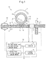
- FIG. 1 is a conceptual view showing a filling device for filling a beer barrel with beer according to the present invention.
- a filling device 10 as shown in Fig. 1 includes: a conveyance passage 11 such as a conveyer for conveying a plurality of barrels, for example, a plurality of beer barrels 40 in the direction of arrow A; and an annular rotary passage 20, which is arranged adjacent to the conveyance passage 11, for successively conveying the beer barrels 40 in the direction of arrow B.
- a conveyance passage 11 such as a conveyer for conveying a plurality of barrels, for example, a plurality of beer barrels 40 in the direction of arrow A
- an annular rotary passage 20 which is arranged adjacent to the conveyance passage 11, for successively conveying the beer barrels 40 in the direction of arrow B.
- a plurality of filling sections 21, for example, twenty filling sections 21 for filling beer into the beer barrels 40 are arranged at regular intervals in the circumferential direction.
- the filling sections F are provided respectively at positions corresponding to the beer barrels 40 located in the rotary passage 20.
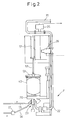
- Fig. 2 is a longitudinal sectional view of a filling section taken along a line I - I in Fig. 1.
- the beer barrel 40 is arranged on the rotary passage 20 in which a metal cap of the beer barrel 40 is directed downward.
- an air cylinder 51 having an extensible rod 52 is provided in an upper portion of the filling device 10.
- a clamp handle 53 At a forward end portion of the rod 52, a clamp handle 53, the configuration of which is a substantial "+", is attached.
- the air cylinder 51 is operated to extend the rod 52, the beer barrel 40 is held between the clamp handle 53 and the rotary passage 20.
- the filling section F includes: a filling head 23 capable of engaging a barrel aperture (not shown) of the beer barrel 40; and a liquid conveyance tube 22 extending from a beer storage tank (not shown) to the filling head 23. Beer in a beer storage tank (not shown) is filled from the barrel aperture into the beer barrel 40 through the liquid conveyance tube 22 and the filling head 23.
- a flow meter 25 for detecting a flow rate of beer flowing in the liquid conveyance tube 22 is arranged in the liquid conveyance tube 22. Further, in the downstream of the flow meter 25 with respect to the flow of beer, a flow control valve 26 for controlling the flow rate of beer is arranged. The flow meter 25 and the flow control valve 26 are electrically connected to the control unit 30 described later.
- a supply tube 55 for supplying pre-stress gas into the beer barrel 40 before beer is filled into the beer barrel 40, and a discharge tube 56 for discharging the pre-stress gas from the beer barrel 40 are shown.
- the pre-stress gas is inert gas, for example, carbon dioxide or nitrogen.
- the pre-stress gas has a function of preventing carbonic dioxide, which is dissolved in beer, from separating or foaming when filling beer into the beer barrel 40.
- a control valve 57 for controlling a flow rate of discharging pre-stress gas is arranged in the discharge tube 56. This control valve 57 is also electrically connected to the control unit 30.
- the beer barrels 40 which has been conveyed onto the conveyance passage 11, are further conveyed into the rotary passage 20 by a star wheel 13 and a guide 14 arranged on the upstream side with respect to conveyance direction A. While the beer barrel 40, which has been conveyed into the rotary passage 20, is being rotated by the rotary passage 20 in the direction of arrow B, beer is filled into the beer barrel 40 by one filling section F.
- a weight measuring means 17 is arranged on the conveyance passage 11 in the downstream of the downstream side star wheel 15.
- the weight measuring means 17 measures a total weight of the beer barrel 40 after beer has been filled into it.
- a branch conveyance passage 18 branches from the conveyance passage 11.
- the branch conveyance passage 18 is not operated. Only when a starting section 19 is set in motion, the branch conveyance passage 18 is operated.
- the starting section 19 is started and the beer barrel 40 concerned is ejected from the conveyance passage 11 into the branch conveyance passage 18. That is, the branch conveyance passage 18 has a function as an ejection means for ejecting the beer barrel 40.
- a stop member 60 described later is arranged in the upstream of the upstream side star wheel 13.
- the weight measuring means 17, the starting section 19 and the stop member 60 are also electrically connected to the control unit 30.
- the control unit 30 is a digital computer, which controls the entire filling device 10.
- the control unit 30 includes: a filling speed type filling failure judging means 31 for judging whether or not a beer barrel 40 is insufficiently filled according to a filling speed of filling beer into the beer barrel 40, and a weight type filling failure judging means 32 for judging whether or not a beer barrel 40 is insufficiently filled according to a weight of the beer barrel 40 after beer has been filled into the beer barrel 40.
- control unit 30 includes: a counter 33 for counting the number of times in which a filling failure is caused in each of the plurality of filling sections F; and a storage section 34 for storing various predetermined values, various measurement values and an operation program 100 described later.
- the filling speed type filling failure judging means 31, the weight type filling failure judging means 32, the counter 33 and the storage section 34 are connected to each other by a bidirectional bus 35.
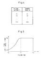
- step 101 of the operation program 100 the present counter value N i of the filling section F i , to which the beer barrel 40 is supplied, is acquired.
- the counter value N 5 of the filling section F 5 is acquired.
- the counter value N i is counted in the counter 33 in the form of a map with respect to each of the plurality of filling sections F i . Accordingly, in this case, the present counter value N 5 in the map may be simply acquired.
- step 102 the empty beer barrel 40 is moved by the upstream side star wheel 13 and the guide 14 from the conveyance passage 11 to the rotary passage 20 and held by the filling section F 5 as described before. While the empty beer barrel 40 is being rotated together with the rotary passage 20, a predetermined weight of pre-stress gas is filled into the beer barrel 40 through the supply pipe line 55. Next, while pre-stress gas is being discharged outside through the discharge pipe line 56, beer is filled into the beer barrel 40 concerned by the filling head 23 of the filling section F 5 .
- Fig. 5 is a graph showing a relationship between the filling time and the signal command value with respect to the flow speed (filling speed) of beer.
- the axis of abscissas represents a filling time of beer.
- the axis of ordinates represents a signal with respect to the flow speed of beer transmitted from the control unit 30. According to the signal command value with respect to the flow speed of beer shown in this graph, the flow speed of beer is actually controlled by the flow control valve 26.
- the flow speed of beer is gradually increased from the flow speed QA to the maximum flow speed QB from the time T 0 to the time T 1 .
- the reason why the flow speed of beer is gradually increased is to prevent carbonic dioxide contained in the beer from separating or foaming at the time of filling.
- beer is continuously filled into the beer barrel 40 at the maximum flow speed QB from the time T 1 to the time T 2 .
- the flow control valve 26 is closed so that the supply of beer can be instantaneously shut off.
- step 103 the actual filling speed V corresponding to the signal command value of the maximum flow speed QB after the time T 1 is measured by the flow meter 25. Specifically, according to the flow rate data, which is transmitted from the flow meter 25 to the control unit 30, and the scanning time, which was previously set, the actual filling speed V of beer is calculated.
- step 104 After a predetermined filling weight of beer has been filled in step 104, the beer barrel 40 concerned is moved to the proximity of the downstream side star wheel 15. Next, the beer barrel 40 concerned is returned from the rotary passage 20 to the conveyance passage 11 by the downstream side star wheel 15 and the guide 16. After that, in step 105, the total weight Z of the beer barrel 40 after beer has been filled into it is measured by the weight measurement means 17. The filling speed V and the total weight Z are temporarily stored in the storage section 34.
- step 106 it is judged by the filling speed type filling failure judging means 31 whether or not the filling speed V is higher than a predetermined value V 0 .
- the predetermined value V 0 is an upper limit value of the filling speed at which beer can be filled into the beer barrel without involving pre-stress gas into a flow of beer. This predetermined value V 0 is previously found by experiments, etc.
- the predetermined value V 0 is, for example, two or three times as high as the maximum flow speed QB (command value) shown in Fig. 5.
- pre-stress gas is involved in a flow of beer at the time of filling beer and that pre-stress gas compressed at a relatively high pressure remains in the beer barrel.
- pre-stress gas is extracted together with beer at the time of extracting beer. Accordingly, there is a high possibility that a large amount of bubbles of large diameters are generated on a level of beer. It is impossible to excellently extract beer from such a beer barrel 40. Accordingly, it is judged that such a beer barrel 40 is not sufficiently filled with beer irrespective of the filling weight of beer actually filled into the beer barrel 40.
- step 108a the branch conveyance passage 18 is started by the starting section 19 in step 108a. Due to the foregoing, the after filling beer barrel 40 concerned is moved from the conveyance passage 11 to the branch conveyance passage 18 and ejected from the filling device 10. Next, in step 109a, "1" is added to the counter value N 5 of the filling section F 5 corresponding to the beer barrel 40 concerned (N 5 ⁇ N 5 + 1).
- step 106 it is judged by the weight type filling failure judging means 32 whether or not the total weight Z of the beer barrel 40 after filling beer is lighter than the predetermined value Z 2 .
- the predetermined value Z 2 is a value obtained by adding the beer filling weight to the maximum value of the empty beer barrel weight previously determined by a statistical method.
- the flow control valve 26 in the filling section F 5 is maintained at a degree of opening in the closing direction as compared with a desired degree of opening, for some reason.
- step 108b the program proceeds to step 108b and the beer barrel 40 concerned is ejected from the filling device 10 as described before. Therefore, even in the case of the beer barrel, the extraction of which is not a failure or the basis of the remaining pre-stress gas, it is possible to prevent a beer barrel 40, which is not sufficiently filled with beer, from being delivered to the market. Further, as described before, in step 109b, "1" is further added to the counter value N 5 of the filling section F 5 which has filled beer into the beer barrel 40 concerned (N 5 ⁇ N 5 + 1).
- step 110 the latest counter value N 5 of the filling section F 5 is read and it is judged whether or not the counter value N 5 is not less than the predetermined value N 0 .
- the predetermined value N 0 is an integer not less than 1.
- the predetermined value N 0 is "trade-off" of the productivity of the filling device 10 and the rate of generation of beer barrels into which beer is not sufficiently filled. That is, in the case where the predetermined value N 0 is relatively high, the productivity of the filling device 10 is increased, however, the rate of generation of beer barrels into which beer is not sufficiently filled, is also increased. On the contrary, in the case where the predetermined value N 0 is relatively low, the rate of generation of beer barrels into which beer is not sufficiently filled is decreased, however, the productivity of the filling device 10 is also decreased.
- the predetermined value N 0 is appropriately decided by an operator according to the relation described above.
- step 111 the flow control valve 26 is closed by the control unit 30 so that beer can not be supplied from a storage tank (not shown) to the filling section F 5 concerned. That is, the flow control valve 26 functions as a liquid filling stop means for stopping beer (liquid) from being filled into a beer barrel at the specific filling section F i , for example, at the filling section F 5 .
- the filling section F 5 does not charge beer into other beer barrels 40. Accordingly, it is possible to avoid the occurrence of a case in which other beer barrels 40 successively fail to be sufficiently filled with beer by this filling section F 5 . Therefore, in the present invention, even in the case of the generation of a filling failure, it is unnecessary to stop the entire filling device 10.
- the stop member 60 is set in motion by the control unit 30 at a predetermined timing, so that a new empty beer barrel 40 can not be supplied to the filling section F5 concerned.
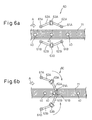
- Figs. 6a and 6b are partially enlarged views in which a portion of the filling device is shown being enlarged so as to explain the stop member.
- the stop member 60 includes: a pair of connecting rods 62A arranged on one side of the conveyance passage 11; and a pair of connecting rods 62B arranged on the other side of the conveyance passage 11 to face to the connecting rods 62A.
- a pair of connecting rods 62A are connected to each other, forming a predetermined angle between them.
- a corner portion of the pair of connecting rods 62A is formed as a rotary shaft portion 63A capable of rotating.
- a corner portion of a pair of connecting rods 62B is formed as a rotary shaft portion 63B capable of rotating.
- the rotary shaft portions 63A, 63B of the stop member 60 are arranged away from the conveyance passage 11.
- the stop member 60 When the rotary passage 20 is further rotated, the stop member 60 is returned to the initial position so that the beer barrel 40 can be released. Accordingly, the beer barrel 40 is supplied to the adjacent filling section F 6 . That is, the stop member 60 can skip a supply of the beer barrel 40 to the filling section F 5 that is out of order.
- the filling section F 5 concerned can be positively prevented from filling beer into the other beer barrels 40. Accordingly, it is possible to positively avoid the occurrence of a case in which the other beer barrels 40 continuously fail to be sufficiently filled with beer.
- This stop member 60 is advantageously used especially when the flow control valve 26 is fixed and it becomes impossible to stop filling beer into a beer barrel, that is, this stop member 60 is advantageously used especially when it is impossible to conduct processing of step 111.
- the filling speed type filling failure judging means 31 and/or the weight type filling failure judging means 32 can be easily judged by the filling speed type filling failure judging means 31 and/or the weight type filling failure judging means 32. Further, even in the case where a beer barrel 40, into which beer is not sufficiently filled, is generated by a specific filling section F i , by using the flow control valve 26 and/or stop member 60, it is possible to prevent the continuous generation of beer barrels 40 into which beer is not sufficiently charge.
- the flow meter 25 is arranged in the upstream of the flow control valve 26.
- the flow meter 25 may be arranged in the downstream of the flow control valve 26, for example, the flow meter 25 may be arranged inside the filling head 23.
- the filling speed of beer is directly measured by the flow meter 25. Therefore, it is apparent that whether or not the beer barrel 40 is sufficiently filled with beer can be more strictly judged.
- steps 106 and 107 and one of steps 111 and 112 may be omitted.
- step 106 an average value of the filling speed V in the filling stage may be compared with another predetermined value.
- a judgment relating to the filling speed V and the predetermined value V 0 in step 106 may be made. In the case where it is judged in the middle of filling beer that the filling speed V is greater than the predetermined value V 0 , the beer filling operation is forcibly stopped so that a waste of beer can be reduced.
- the filling time in a case where the filling time is shorter than a predetermined value, it may be judged to be a failure of filling beer by using the filling time instead of the filling speed V in step 106.
- the filling time in a case where the filling time is longer than another predetermined value, it may be judged to be a failure of filling beer by using the filling time instead of the total weight Z in step 107. It is clear that even the above cases are included in the scope of the present invention.
Landscapes
- Engineering & Computer Science (AREA)
- Mechanical Engineering (AREA)
- Filling Of Jars Or Cans And Processes For Cleaning And Sealing Jars (AREA)
- Basic Packing Technique (AREA)
- Vehicle Body Suspensions (AREA)
Abstract
Description
- The present invention relates to a filling failure judging device for judging whether or not a container to be filled with a liquid, for example, a beer barrel to be filled with beer is insufficiently filled. Further, the present invention relates to a filling device, having such a filling failure judging device, for filling beer into a container, for example, a beer barrel.
- Generally, beer is sold in bottles or cans. In addition, beer is also sold in glasses or mugs. In such a case, beer is filled into beer barrels or tanks, which are exclusively used for beer, in breweries and then delivered to restaurants, etc. In the restaurants, etc., beer is poured into the glasses or mugs exclusively through dispensers attached to the beer barrels.
- In breweries, beer is filled into beer barrels by a filling device. The filling device includes a plurality of filling sections. Each filling section includes: a flow control valve for adjusting a flow rate of beer; and a filling head.
- At the time of filling beer into a beer barrel, pre-stress gas, for example, inert gas is previously filled into the beer barrel so that the beer barrel can be pre-stressed at a predetermined pressure. Pre-stress gas prevents carbonic dioxide, which is dissolved in beer, from separating from the beer at the time of filling beer into the beer barrel, and prevents the beer itself from foaming when filling the beer into the beer barrel. At the time of filling beer, pre-stress gas is gradually discharged from the beer barrel according to a filling weight of beer so that the pressure in the beer barrel can be maintained constant.
- However, in the case where the flow control valve of the filling section is fully opened, a filling speed of beer is extremely increased. Due to this, pre-stress gas, which should be originally discharged, gets mixed in with the flow of beer and is compressed in the beer barrel at a relatively high pressure in some cases.
- When beer is extracted from the beer barrel, in which pre-stress gas is compressed as described above, exclusively through a dispenser, the pre-stress gas is also extracted together with beer. Therefore, an extracting speed of beer is considerably increased. Accordingly, a large amount of bubbles, the diameters of which are larger than those of bubbles in a usual case, are generated. In other words, in this case, it is impossible to form fine bubbles on a level of beer, which is not preferable for consumers.
- In the case where the filling section has made an insufficiently filled beer barrel in which pre-stress gas is compressed as described above, there is a high possibility that the filling section successively makes a similar beer barrel, into which beer is not sufficiently filled. Accordingly, in the case where the beer barrel, into which beer is not sufficiently filled, is made in a specific filling section, it is estimated that operation of the specific filling section is stopped.
-
Japanese Unexamined Patent Publication No. 2000-289720 Japanese Unexamined Patent Publication No. 2000-289720 - However, in the case where an operation of the entire filling device is stopped and a filling section, which has caused the failure of filling, in a plurality of filling sections is specified, each time a failure of filling is caused, productivity is deteriorated, which is not practical.
- Whether or not a beer barrel has been insufficiently filled with beer by the filling section is found in many cases when beer is actually extracted from the beer barrel through an exclusively used dispenser in a shop after the beer barrel has been delivered to the market. Therefore, in the case where a beer barrel, into which beer was not sufficiently filled with beer, is discovered in the shop, there is a high possibility that a large number of beer barrels, into which beer was not sufficiently filled with beer, have already been delivered to the market. It is possible to conduct checking in breweries to determine whether or not beer barrels are sufficiently filled with beer. However, this checking operation is complicated. Further, it takes time to check whether or not beer barrels are sufficiently filled.
- The present inventors earnestly made investigation into the above matter so as to solve the problems. As a result of their investigation, the present inventors acquired knowledge in which whether or not a beer barrel is sufficiently filled with beer can be easily and quickly judged before the beer barrel is delivered to the market, in other words, at the time of filling beer into the beer barrel, by measuring a filling speed of beer.
- The present invention has been accomplished in view of the above circumstances. The object of the present invention is to provide a filling failure judging device capable of easily and quickly judging that a container, for example, a beer barrel is not sufficiently filled with beer. Another object of the present invention is to provide a filling device having such a filling failure judging device.
- In order to accomplish the above object, the first aspect provides a filling failure judging device comprising a filling speed measurement means for measuring a filling speed of filling a liquid into a container by one of a plurality of liquid filling means for filling a predetermined weight of liquid into each of a plurality of containers, wherein in the case where the filling speed measured by the filling speed measurement means is higher than a predetermined value, the container filled with the liquid by the filling speed is judged to be a container insufficiently filled with the liquid.
- In the first aspect, in the case where a filling speed of filling a liquid is relatively low, no pre-stress gas is involved in beer. Accordingly, no pre-stress gas remains in the container. Therefore, when it is judged whether or not the filling speed of filling the liquid is higher than a predetermined value, it can be judged whether or not the container is insufficiently filled. Accordingly, it is possible to easily find a container into which the liquid is not sufficiently filled. In this connection, the filling speed may be the maximum value or the average value at the time of filling the liquid.
- According to the second aspect, as in the first aspect, a filling failure judging device further comprises an after filling container weight measurement means for measuring a weight of each container after the liquid has been filled into the container by each liquid filling means, wherein in the case where a weight of the container measured by the after filling container weight measurement means is lighter than a predetermined after-filling container reference weight, the container is judged to be a container insufficiently filled with the liquid.
- In other words, in the second aspect, it is judged whether or not a container, in which pre-stress gas is compressed, is not sufficiently filled. Further, it is judged whether or not a filling weight of the container is lighter than a predetermined weight, in other words, whether or not the container is not sufficiently filled. Therefore, it is easy to find a container which is not sufficiently filled with a liquid.
- The third aspect provides a filling device comprising a filling failure judging device as in the first or the second aspect.
- In other words, in the third aspect, it is possible to judge whether or not a container is not sufficiently filled before it is delivered to the market, that is, at the time of filling a liquid into the container. Therefore, a filling failure container can be easily found.
- The fourth aspect provides a filling device in the third aspect, further comprising an ejection means for ejecting the container, which has been judged to be insufficiently filled with the liquid, from the filling device.
- In other words, in the fourth aspect, it is possible to prevent a container, which is not sufficiently filled, from circulating in the market.
- The fifth aspect provides a filling device as in the third or the fourth aspect, further comprising a liquid filling stop means for stopping filling the liquid into the container by the liquid filling means which corresponds to the container judged to be insufficiently filled with the liquid in the case where the number of times of the cases, in which it is judged that the container is not sufficiently filled, is not less than a predetermined number of times.
- In other words, in the fifth aspect, in order to prevent the generation of a container which is not sufficiently filled, a liquid is not filled by the liquid filling means concerned. Accordingly, it is possible to exclude the necessity to stop the entire filling device. The liquid filling stop means is, for example, a flow control valve provided in the liquid filling means.
- The sixth aspect provides a filling device as in any one of the third to the fifth aspect, further comprising a container supply stop means for stopping supplying a new container to the liquid filling means which corresponds to the container judged to be insufficiently filled with the liquid in the case where the number of times of the cases, in which it is judged that the container is not sufficiently filled, is not less than a predetermined number of times.
- In other words, in the sixth aspect, in order to prevent the generation of a container which is not sufficiently filled, a container is not supplied to the liquid filling means concerned. Accordingly, it is possible to exclude the necessity to stop the entire filling device. The container supply stop means is, for example, a means for skipping a supply of a barrel to the liquid filling means by temporarily holding the barrel from both sides of the conveyance passage.
- The seventh aspect provides a filling device for filling a liquid into a container comprising: a plurality of liquid filling means for respectively filling a predetermined weight of liquid into a plurality of containers; a filling failure judging means for judging the containers, into which the liquid is filled by the plurality of liquid filling means, to be insufficiently filled; and a liquid filling stop means for stopping filling the liquid into the container by the liquid filling means which corresponds to the container judged to be insufficiently filled in the case where the number of times of the cases, in which it is judged by the filling failure judging means that the container is insufficiently filled, is not less than a predetermined number of times.
- In other words, in the seventh aspect, in order to prevent the generation of a container which is not sufficiently filled, the liquid is not filled into the container from the liquid filling means concerned. Accordingly, it is possible to exclude the necessity to stop the entire filling device. Before the container is delivered to the market, that is, at the time of filling the liquid, it can be judged whether or not the container is not sufficiently filled. Therefore, the container, which is not sufficiently filled, can be easily found. The liquid filling stop means is, for example, a flow control valve provided in the liquid filling means.
- The eighth aspect provides a filling device for filling a liquid into a container comprising: a plurality of liquid filling means for respectively filling a predetermined weight of liquid into a plurality of containers; a filling failure judging means for judging the containers, into which the liquid is filled by the plurality of liquid filling means, to be insufficiently filled; and a container supply stop means for stopping supplying a new container to the liquid filling means which corresponds to the container judged to be insufficiently filled in the case where the number of times of the cases, in which it is judged by the filling failure judging means that the container is insufficiently filled, is not less than a predetermined number of times.
- In other words, in the eighth aspect, in order to prevent the generation of a container which is not sufficiently filled, a container is not supplied to the liquid filling means concerned. Accordingly, it is possible to exclude the necessity to stop the entire filling device. Before the container is delivered to the market, that is, at the time of filling the liquid, it can be judged whether or not the container is not sufficiently filled. Therefore, the container, which is not sufficiently filled, can be easily found. For example, the container supply stop means is a means for skipping a supply of the barrel, which is conveyed along a conveyance passage, to the liquid filling means concerned by temporarily holding the barrel from both sides of the conveyance passage.
- According to the ninth aspect, as in the seventh or the eighth aspect, the filling failure judging means includes a filling speed measurement means for measuring a filling speed at the time of filling the liquid into each container by the plurality of liquid filling means, and the filling failure judging means judges that the container, into which the liquid is filled by a filling speed, is not sufficiently filled in the case where the filling speed measured by the filling speed measuring means is higher than a predetermined value.
- In other words, in the ninth aspect, in the case where a filling speed of the beverage is relatively low, no pre-stress gas is involved in beer. Accordingly, no pre-stress gas remains in the container. Therefore, when it is judged whether or not the filling speed of the liquid is higher than a predetermined value, it is possible to judge whether or not the container is sufficiently filled. Therefore, the container, into which the liquid is not sufficiently filled, can be easily found. In this connection, the filling speed may be the maximum value or the average value at the time of filling the liquid.
- According to the tenth aspect, as in the seventh or the eighth aspect, the filling failure judging means includes an after filling container weight measurement means for measuring a weight of each container into which the beverage is filled by each liquid filling means, and the filling failure judging means judges that a container is not sufficiently filled in the case where a weight of the container, which is measured by the after filling container weight measurement means, is lighter than a predetermined after-filling container reference weight.
- In other words, in the tenth aspect, it is judged whether or not the filling weight is lighter than a predetermined weight. In other words, it is judged whether or not the container is not sufficiently filled. Therefore, a filling failure container can be easily found.
- The eleventh aspect provides a filling device for filling a liquid into a container according to any one of the seventh to the tenth aspect, further comprising an ejection means for ejecting the container, which is judged to be insufficiently filled, from the filling device.
- In other words, in the eleventh aspect, it is possible to prevent a container, which is not sufficiently filled with a liquid, from circulating in the market.
- These and other objects, the characteristics and the advantages of the present invention will become more apparent in the detailed description of the typical embodiments of the present invention shown in the accompanying drawings.
-
- Fig. 1 is a conceptual view showing a filling device for filling a beer barrel with beer according to the present invention.
- Fig. 2 is a longitudinal sectional view of a filling section taken along a line I - I in Fig. 1.
- Fig. 3 is a flow chart showing an operation program of a filling device of the present invention.
- Fig. 4 is a view showing a map of a plurality of filling sections and counter values.
- Fig. 5 is a view showing a relationship between the filling time and the signal command value with respect to the flow velocity of beer.
- Fig. 6a is a first partially enlarged view showing a portion of the filling device for explaining a stop member.
- Fig. 6b is a second partially enlarged view showing a portion of the filling device for explaining a stop member.
- Referring to the accompanying drawings, an embodiment of the present invention will be explained below. Like reference characters are used to indicate like parts in the following drawings. In order to facilitate understanding, the scale has been appropriately changed. In this connection, in the case of the following explanation, beer is filled into beer barrels. However, it should be noted that the above case is only an example and the present invention includes all cases in which a liquid is filled into containers.
- Fig. 1 is a conceptual view showing a filling device for filling a beer barrel with beer according to the present invention. A filling
device 10 as shown in Fig. 1 includes: aconveyance passage 11 such as a conveyer for conveying a plurality of barrels, for example, a plurality of beer barrels 40 in the direction of arrow A; and anannular rotary passage 20, which is arranged adjacent to theconveyance passage 11, for successively conveying the beer barrels 40 in the direction of arrow B. - In the
rotary passage 20, a plurality of filling sections 21, for example, twenty filling sections 21 for filling beer into the beer barrels 40 are arranged at regular intervals in the circumferential direction. In Fig. 1, the filling sections F are provided respectively at positions corresponding to the beer barrels 40 located in therotary passage 20. - Fig. 2 is a longitudinal sectional view of a filling section taken along a line I - I in Fig. 1. In Fig. 2, the
beer barrel 40 is arranged on therotary passage 20 in which a metal cap of thebeer barrel 40 is directed downward. In an upper portion of the fillingdevice 10, anair cylinder 51 having anextensible rod 52 is provided. At a forward end portion of therod 52, aclamp handle 53, the configuration of which is a substantial "+", is attached. When theair cylinder 51 is operated to extend therod 52, thebeer barrel 40 is held between the clamp handle 53 and therotary passage 20. - The filling section F includes: a filling
head 23 capable of engaging a barrel aperture (not shown) of thebeer barrel 40; and aliquid conveyance tube 22 extending from a beer storage tank (not shown) to the fillinghead 23. Beer in a beer storage tank (not shown) is filled from the barrel aperture into thebeer barrel 40 through theliquid conveyance tube 22 and the fillinghead 23. - As shown in the drawing, in the
liquid conveyance tube 22, aflow meter 25 for detecting a flow rate of beer flowing in theliquid conveyance tube 22 is arranged. Further, in the downstream of theflow meter 25 with respect to the flow of beer, aflow control valve 26 for controlling the flow rate of beer is arranged. Theflow meter 25 and theflow control valve 26 are electrically connected to thecontrol unit 30 described later. - Further, in Fig. 2, a
supply tube 55 for supplying pre-stress gas into thebeer barrel 40 before beer is filled into thebeer barrel 40, and adischarge tube 56 for discharging the pre-stress gas from thebeer barrel 40 are shown. The pre-stress gas is inert gas, for example, carbon dioxide or nitrogen. The pre-stress gas has a function of preventing carbonic dioxide, which is dissolved in beer, from separating or foaming when filling beer into thebeer barrel 40. In this connection, in thedischarge tube 56, acontrol valve 57 for controlling a flow rate of discharging pre-stress gas is arranged. Thiscontrol valve 57 is also electrically connected to thecontrol unit 30. Although the details are not explained here, pre-stress gas supplied to thebeer barrel 40 is discharged through thedischarge pipe line 56 in accordance with the progress of the filling operation of beer. - Referring to Fig. 1 again, the beer barrels 40, which has been conveyed onto the
conveyance passage 11, are further conveyed into therotary passage 20 by astar wheel 13 and aguide 14 arranged on the upstream side with respect to conveyance direction A. While thebeer barrel 40, which has been conveyed into therotary passage 20, is being rotated by therotary passage 20 in the direction of arrow B, beer is filled into thebeer barrel 40 by one filling section F. - In other words, while the
rotary passage 20 is being rotated from a beer barrel injecting position at the upstreamside star wheel 13 to a beer barrel ejecting position at the downstreamside star wheel 15, a predetermined amount of beer is filled into thebeer barrel 40. Thebeer barrel 40 filled with beer is returned to theconveyance passage 11 by thestar wheel 15 and theguide 16 on the downstream side. Since the filling device is composed as described above, in a filling section Fa located between thestar wheels - In the filling
device 10, a weight measuring means 17 is arranged on theconveyance passage 11 in the downstream of the downstreamside star wheel 15. The weight measuring means 17 measures a total weight of thebeer barrel 40 after beer has been filled into it. - As shown in the drawing, in the downstream of the weight measuring means 17, a
branch conveyance passage 18 branches from theconveyance passage 11. Usually, thebranch conveyance passage 18 is not operated. Only when astarting section 19 is set in motion, thebranch conveyance passage 18 is operated. In the case where the total weight of thebeer barrel 40, which has been measured by the weight measuring means 17, is lighter than the predetermined value Z2, thestarting section 19 is started and thebeer barrel 40 concerned is ejected from theconveyance passage 11 into thebranch conveyance passage 18. That is, thebranch conveyance passage 18 has a function as an ejection means for ejecting thebeer barrel 40. Further, in the upstream of the upstreamside star wheel 13, astop member 60 described later is arranged. - The weight measuring means 17, the
starting section 19 and thestop member 60 are also electrically connected to thecontrol unit 30. In this case, thecontrol unit 30 is a digital computer, which controls theentire filling device 10. - As shown in Fig. 1, the
control unit 30 includes: a filling speed type filling failure judging means 31 for judging whether or not abeer barrel 40 is insufficiently filled according to a filling speed of filling beer into thebeer barrel 40, and a weight type filling failure judging means 32 for judging whether or not abeer barrel 40 is insufficiently filled according to a weight of thebeer barrel 40 after beer has been filled into thebeer barrel 40. - Further, the
control unit 30 includes: acounter 33 for counting the number of times in which a filling failure is caused in each of the plurality of filling sections F; and astorage section 34 for storing various predetermined values, various measurement values and anoperation program 100 described later. As shown in the drawing, the filling speed type filling failure judging means 31, the weight type filling failure judging means 32, thecounter 33 and thestorage section 34 are connected to each other by abidirectional bus 35. - Fig. 3 is a flow chart showing an operation program of a filling device according to the first embodiment of the present invention. Referring to Fig. 3, operation of the filling device according to the present invention will be explained as follows. This
operation program 100 is executed for each of the plurality of filling sections F at the time of normal operation of the fillingdevice 10. In this connection, in the following explanations, the plurality of filling sections F will be referred to as the filling section Fi (i = 1 to 20). - In
step 101 of theoperation program 100, the present counter value Ni of the filling section Fi, to which thebeer barrel 40 is supplied, is acquired. For example, in the case where thebeer barrel 40 is supplied to one filling section F5 of the filling section Fi, the counter value N5 of the filling section F5 is acquired. As shown in Fig. 4, the counter value Ni is counted in thecounter 33 in the form of a map with respect to each of the plurality of filling sections Fi. Accordingly, in this case, the present counter value N5 in the map may be simply acquired. - Next, in
step 102, theempty beer barrel 40 is moved by the upstreamside star wheel 13 and theguide 14 from theconveyance passage 11 to therotary passage 20 and held by the filling section F5 as described before. While theempty beer barrel 40 is being rotated together with therotary passage 20, a predetermined weight of pre-stress gas is filled into thebeer barrel 40 through thesupply pipe line 55. Next, while pre-stress gas is being discharged outside through thedischarge pipe line 56, beer is filled into thebeer barrel 40 concerned by the fillinghead 23 of the filling section F5. - Fig. 5 is a graph showing a relationship between the filling time and the signal command value with respect to the flow speed (filling speed) of beer. In Fig. 5, the axis of abscissas represents a filling time of beer. The axis of ordinates represents a signal with respect to the flow speed of beer transmitted from the
control unit 30. According to the signal command value with respect to the flow speed of beer shown in this graph, the flow speed of beer is actually controlled by theflow control valve 26. - As shown in Fig. 5, the flow speed of beer is gradually increased from the flow speed QA to the maximum flow speed QB from the time T0 to the time T1. The reason why the flow speed of beer is gradually increased is to prevent carbonic dioxide contained in the beer from separating or foaming at the time of filling. Next, when the flow speed of beer is increased to the maximum flow speed QB, beer is continuously filled into the
beer barrel 40 at the maximum flow speed QB from the time T1 to the time T2. After that, at the time T2, theflow control valve 26 is closed so that the supply of beer can be instantaneously shut off. - Referring again to Fig. 3, in
step 103, the actual filling speed V corresponding to the signal command value of the maximum flow speed QB after the time T1 is measured by theflow meter 25. Specifically, according to the flow rate data, which is transmitted from theflow meter 25 to thecontrol unit 30, and the scanning time, which was previously set, the actual filling speed V of beer is calculated. - After a predetermined filling weight of beer has been filled in
step 104, thebeer barrel 40 concerned is moved to the proximity of the downstreamside star wheel 15. Next, thebeer barrel 40 concerned is returned from therotary passage 20 to theconveyance passage 11 by the downstreamside star wheel 15 and theguide 16. After that, instep 105, the total weight Z of thebeer barrel 40 after beer has been filled into it is measured by the weight measurement means 17. The filling speed V and the total weight Z are temporarily stored in thestorage section 34. - Next, in
step 106, it is judged by the filling speed type filling failure judging means 31 whether or not the filling speed V is higher than a predetermined value V0. The predetermined value V0 is an upper limit value of the filling speed at which beer can be filled into the beer barrel without involving pre-stress gas into a flow of beer. This predetermined value V0 is previously found by experiments, etc. The predetermined value V0 is, for example, two or three times as high as the maximum flow speed QB (command value) shown in Fig. 5. - In the case where it is judged in
step 106 that the filling speed V is higher than the predetermined value V0, it can be decided that pre-stress gas is involved in a flow of beer at the time of filling beer and that pre-stress gas compressed at a relatively high pressure remains in the beer barrel. As described before, in such abeer barrel 40, pre-stress gas is extracted together with beer at the time of extracting beer. Accordingly, there is a high possibility that a large amount of bubbles of large diameters are generated on a level of beer. It is impossible to excellently extract beer from such abeer barrel 40. Accordingly, it is judged that such abeer barrel 40 is not sufficiently filled with beer irrespective of the filling weight of beer actually filled into thebeer barrel 40. - Therefore, in the case where the filling speed V is judged to be higher than the predetermined value V0, the
branch conveyance passage 18 is started by thestarting section 19 instep 108a. Due to the foregoing, the after fillingbeer barrel 40 concerned is moved from theconveyance passage 11 to thebranch conveyance passage 18 and ejected from the fillingdevice 10. Next, instep 109a, "1" is added to the counter value N5 of the filling section F5 corresponding to thebeer barrel 40 concerned (N5 ← N5 + 1). - On the other hand, in the case where it is judged in
step 106 that the filling speed V is not higher than the predetermined value V0, the program proceeds to step 107. Instep 107, it is judged by the weight type filling failure judging means 32 whether or not the total weight Z of thebeer barrel 40 after filling beer is lighter than the predetermined value Z2. The predetermined value Z2 is a value obtained by adding the beer filling weight to the maximum value of the empty beer barrel weight previously determined by a statistical method. - In the case where the total weight Z of the
beer barrel 40 is lighter than the predetermined value Z2 instep 107, since the beer filling weight of thebeer barrel 40 concerned is lighter than the predetermined beer filling weight, it is determined that thebeer barrel 40 concerned is insufficiently filled with beer. For example, theflow control valve 26 in the filling section F5 is maintained at a degree of opening in the closing direction as compared with a desired degree of opening, for some reason. - It is impossible to deliver such a
beer barrel 40 into which beer is not sufficiently filled. Therefore, the program proceeds to step 108b and thebeer barrel 40 concerned is ejected from the fillingdevice 10 as described before. Therefore, even in the case of the beer barrel, the extraction of which is not a failure or the basis of the remaining pre-stress gas, it is possible to prevent abeer barrel 40, which is not sufficiently filled with beer, from being delivered to the market. Further, as described before, instep 109b, "1" is further added to the counter value N5 of the filling section F5 which has filled beer into thebeer barrel 40 concerned (N5 ← N5 + 1). - Next, in
step 110, the latest counter value N5 of the filling section F5 is read and it is judged whether or not the counter value N5 is not less than the predetermined value N0. The predetermined value N0 is an integer not less than 1. When it is judged instep 110 that the counter value N5 is not more than the predetermined value No, processing is finished. - The predetermined value N0 is "trade-off" of the productivity of the filling
device 10 and the rate of generation of beer barrels into which beer is not sufficiently filled. That is, in the case where the predetermined value N0 is relatively high, the productivity of the fillingdevice 10 is increased, however, the rate of generation of beer barrels into which beer is not sufficiently filled, is also increased. On the contrary, in the case where the predetermined value N0 is relatively low, the rate of generation of beer barrels into which beer is not sufficiently filled is decreased, however, the productivity of the fillingdevice 10 is also decreased. The predetermined value N0 is appropriately decided by an operator according to the relation described above. - In the case where the counter value N5 is not less than the predetermined value N0 in
step 110, that is, in the case where the number of times, at which thebeer barrel 40 filled with beer by the filling section F5 is judged to be insufficiently filled, is relatively large, the program proceeds to step 111. Instep 111, theflow control valve 26 is closed by thecontrol unit 30 so that beer can not be supplied from a storage tank (not shown) to the filling section F5 concerned. That is, theflow control valve 26 functions as a liquid filling stop means for stopping beer (liquid) from being filled into a beer barrel at the specific filling section Fi, for example, at the filling section F5. - Due to the foregoing, even when the filling
device 10 is successively operated, the filling section F5 does not charge beer into other beer barrels 40. Accordingly, it is possible to avoid the occurrence of a case in which other beer barrels 40 successively fail to be sufficiently filled with beer by this filling section F5. Therefore, in the present invention, even in the case of the generation of a filling failure, it is unnecessary to stop theentire filling device 10. - Further, in
step 112, thestop member 60 is set in motion by thecontrol unit 30 at a predetermined timing, so that a newempty beer barrel 40 can not be supplied to the filling section F5 concerned. Figs. 6a and 6b are partially enlarged views in which a portion of the filling device is shown being enlarged so as to explain the stop member. In these drawings, thestop member 60 includes: a pair of connectingrods 62A arranged on one side of theconveyance passage 11; and a pair of connectingrods 62B arranged on the other side of theconveyance passage 11 to face to the connectingrods 62A. - As shown in the drawing, a pair of connecting
rods 62A are connected to each other, forming a predetermined angle between them. A corner portion of the pair of connectingrods 62A is formed as arotary shaft portion 63A capable of rotating. In the same manner, a corner portion of a pair of connectingrods 62B is formed as arotary shaft portion 63B capable of rotating. As can be seen from Fig. 6a, therotary shaft portions stop member 60 are arranged away from theconveyance passage 11. - As shown in Fig. 6b, when the
stop member 60 is set in motion, the pair of the connectingrods rotary shaft portions end portions rods conveyance passage 11. Accordingly, thebeer barrel 40 conveyed in theconveyance passage 11 is temporarily stopped by oneend portions rods beer barrel 40 is not supplied to the filling section F5 concerned. When therotary passage 20 is further rotated, thestop member 60 is returned to the initial position so that thebeer barrel 40 can be released. Accordingly, thebeer barrel 40 is supplied to the adjacent filling section F6. That is, thestop member 60 can skip a supply of thebeer barrel 40 to the filling section F5 that is out of order. - In this case, the filling section F5 concerned can be positively prevented from filling beer into the other beer barrels 40. Accordingly, it is possible to positively avoid the occurrence of a case in which the other beer barrels 40 continuously fail to be sufficiently filled with beer. This
stop member 60 is advantageously used especially when theflow control valve 26 is fixed and it becomes impossible to stop filling beer into a beer barrel, that is, thisstop member 60 is advantageously used especially when it is impossible to conduct processing ofstep 111. - As described above, in the present invention, whether or not the
beer barrel 40 is not sufficiently filled can be easily judged by the filling speed type filling failure judging means 31 and/or the weight type filling failure judging means 32. Further, even in the case where abeer barrel 40, into which beer is not sufficiently filled, is generated by a specific filling section Fi, by using theflow control valve 26 and/or stopmember 60, it is possible to prevent the continuous generation of beer barrels 40 into which beer is not sufficiently charge. - In the embodiment explained referring to the drawings, the
flow meter 25 is arranged in the upstream of theflow control valve 26. However, theflow meter 25 may be arranged in the downstream of theflow control valve 26, for example, theflow meter 25 may be arranged inside the fillinghead 23. In this case, the filling speed of beer is directly measured by theflow meter 25. Therefore, it is apparent that whether or not thebeer barrel 40 is sufficiently filled with beer can be more strictly judged. - One of
steps steps step 106, an average value of the filling speed V in the filling stage may be compared with another predetermined value. - In an embodiment not shown in the drawing, before the completion of filling beer in
step 104 of Fig. 3, a judgment relating to the filling speed V and the predetermined value V0 instep 106 may be made. In the case where it is judged in the middle of filling beer that the filling speed V is greater than the predetermined value V0, the beer filling operation is forcibly stopped so that a waste of beer can be reduced. - Further, in an embodiment not shown in the drawing, in a case where the filling time is shorter than a predetermined value, it may be judged to be a failure of filling beer by using the filling time instead of the filling speed V in
step 106. In the same manner, in a case where the filling time is longer than another predetermined value, it may be judged to be a failure of filling beer by using the filling time instead of the total weight Z instep 107. It is clear that even the above cases are included in the scope of the present invention. - The present invention has been explained above referring to the typical embodiment. However, it should be noted that various changes, omissions and additions can be made by those skilled in the art without departing from the scope of the present invention.
Claims (11)
- A filling failure judging device comprising a filling speed measurement means for measuring a filling speed of filling a liquid into a container by one of a plurality of liquid filling means for filling a predetermined weight of liquid into each of a plurality of containers, whereinin the case where the filling speed measured by the filling speed measurement means is higher than a predetermined value, the container filled with the liquid by the filling speed is judged to be a container insufficiently filled with the liquid.
- A filling failure judging device according to claim 1, further comprising an after-filling container weight measurement means for measuring a weight of each container after the liquid has been filled into the container by each liquid filling means, whereinin the case where a weight of the container measured by the after-filling container weight measurement means is lighter than a predetermined after-filling container reference weight, the container is judged to be a container insufficiently filled with the liquid.
- A filling device comprising a filling failure judging device according to claim 1 or 2.
- A filling device according to claim 3, further comprising an ejection means for ejecting the container, which has been judged to be insufficiently filled with the liquid, from the filling device.
- A filling device according to claim 3 or 4, further comprising a liquid filling stop means for stopping filling the liquid into the container by the liquid filling means which corresponds to the container judged to be insufficiently filled with the liquid in the case where the number of times of the cases, in which it is judged that the container is not sufficiently filled, is not less than a predetermined number of times.
- A filling device according to any one of claims 3 to 5, further comprising a container supply stop means for stopping supplying a new container to the liquid filling means which corresponds to the container judged to be insufficiently filled with the liquid in the case where the number of times of the cases, in which it is judged that the container is not sufficiently filled, is not less than a predetermined number of times.
- A filling device for filling a liquid into a container comprising:a plurality of liquid filling means for respectively filling a predetermined weight of liquid into a plurality of containers;a filling failure judging means for judging the containers, into which the liquid is filled by the plurality of liquid filling means, to be insufficiently filled; anda liquid filling stop means for stopping filling the liquid into the container by the liquid filling means which corresponds to the container judged to be insufficiently filled in the case where the number of times of the cases, in which it is judged by the filling failure judging means that the container is insufficiently filled, is not less than a predetermined number of times.
- A filling device for filling a liquid into a container comprising:a plurality of liquid filling means for respectively filling a predetermined weight of liquid into a plurality of containers;a filling failure judging means for judging the containers, into which the liquid is filled by the plurality of liquid filling means, to be insufficiently filled; anda container supply stop means for stopping supplying a new container to the liquid filling means which corresponds to the container judged to be insufficiently filled in the case where the number of times of the cases, in which it is judged by the filling failure judging means that the container is insufficiently filled, is not less than a predetermined number of times.
- A filling device for filling a liquid into a container according to claim 7 or 8, wherein the filling failure judging means includes a filling speed measurement means for measuring a filling speed at the time of filling the liquid into each container by the plurality of liquid filling means, andthe filling failure judging means judges that the container, into which the liquid is filled by a filling speed, is not sufficiently filled in the case where the filling speed measured by the filling speed measuring means is higher than a predetermined value.
- A filling device for filling a liquid into a container according to claim 7 or 8, wherein the filling failure judging means includes an after-filling container weight measurement means for measuring a weight of each container into which the liquid is filled by each beverage filling means, andthe filling failure judging means judges that a container is not sufficiently filled in the case where a weight of the container, which is measured by the after-filling container weight measurement means, is lighter than a predetermined after-filling container reference weight.
- A filling device for filling a liquid into a container according to any one of claims 7 to 10, further comprising an ejection means for ejecting the container, which is judged to be insufficiently filled, from the filling device.
Applications Claiming Priority (1)
| Application Number | Priority Date | Filing Date | Title |
|---|---|---|---|
| JP2006245448A JP4342544B2 (en) | 2006-09-11 | 2006-09-11 | Poor filling judgment device and filling device |
Publications (2)
| Publication Number | Publication Date |
|---|---|
| EP1897848A1 true EP1897848A1 (en) | 2008-03-12 |
| EP1897848B1 EP1897848B1 (en) | 2011-04-06 |
Family
ID=38668703
Family Applications (1)
| Application Number | Title | Priority Date | Filing Date |
|---|---|---|---|
| EP07253588A Not-in-force EP1897848B1 (en) | 2006-09-11 | 2007-09-10 | Filling failure judging device and filling device |
Country Status (6)
| Country | Link |
|---|---|
| EP (1) | EP1897848B1 (en) |
| JP (1) | JP4342544B2 (en) |
| CN (1) | CN101143696B (en) |
| AT (1) | ATE504540T1 (en) |
| DE (1) | DE602007013660D1 (en) |
| TW (1) | TWI336311B (en) |
Cited By (4)
| Publication number | Priority date | Publication date | Assignee | Title |
|---|---|---|---|---|
| WO2009136380A1 (en) * | 2008-05-09 | 2009-11-12 | Aygaz Anonim Sirketi | A control system |
| EP2974998A1 (en) * | 2014-07-18 | 2016-01-20 | Krones AG | Method and device for filling a container with a fill product |
| EP3202704A1 (en) * | 2016-02-08 | 2017-08-09 | Sidel Participations | Method for detecting the defective status of an article to be contact filled with a pourable product and filling device |
| WO2019110218A1 (en) * | 2017-12-04 | 2019-06-13 | Khs Gmbh | Filling station |
Families Citing this family (5)
| Publication number | Priority date | Publication date | Assignee | Title |
|---|---|---|---|---|
| DE102009041160B4 (en) * | 2009-09-14 | 2018-02-22 | Krones Aktiengesellschaft | Device for producing liquid containers |
| CN102530807A (en) * | 2010-12-27 | 2012-07-04 | 薛海盛 | Bottle distribution system of filling machine and filling machine |
| CN104960707A (en) * | 2015-06-05 | 2015-10-07 | 苏州亚思科精密数控有限公司 | Leakage detection system of packaging production line |
| CN111792609B (en) * | 2020-06-15 | 2022-06-17 | 佛山市大象新材料制造有限公司 | Automatic adjust high molecular coating partial shipment device of charge capacity |
| CN112937933B (en) * | 2021-04-25 | 2025-11-07 | 瑞阳制药股份有限公司 | Intelligent split charging machine |
Citations (9)
| Publication number | Priority date | Publication date | Assignee | Title |
|---|---|---|---|---|
| DE2536238A1 (en) * | 1975-08-14 | 1977-02-24 | Holstein & Kappert Maschf | Barrel processing control system - operated by remote control using ultrasonic transmitter |
| DE3034654A1 (en) * | 1980-09-13 | 1982-03-25 | Hermann 8404 Wörth Kronseder | Automatic bottle filling machine - has sensors and detection system to identify location of faulty filling valves |
| GB2098758A (en) * | 1981-04-22 | 1982-11-24 | Shell Int Research | Method and system for continuously monitoring and controlling a set of filling posts for gas bottles |
| US4878333A (en) * | 1988-01-20 | 1989-11-07 | Peco Controls Corporation | Filler line monitoring system with autosynchronization |
| WO1990015755A1 (en) * | 1989-06-12 | 1990-12-27 | A.G. (Patents) Limited | Filling containers |
| US5515888A (en) * | 1993-10-29 | 1996-05-14 | Graffin Andre J J | Measuring weight by integrating flow |
| JP2000289720A (en) | 1999-04-07 | 2000-10-17 | Ishida Co Ltd | Packaging weighing inspection system |
| DE19925039A1 (en) * | 1999-06-01 | 2000-12-07 | Till Gea Gmbh & Co | Method and balance control device for calibrating filling machines with several filling points incorporates a filling machine designed as a round filling appliance with numerous filling points for casks, especially kegs. |
| DE102004005382A1 (en) * | 2004-02-03 | 2005-09-01 | Endress + Hauser Flowtec Ag, Reinach | Method for filling a medium |
Family Cites Families (6)
| Publication number | Priority date | Publication date | Assignee | Title |
|---|---|---|---|---|
| JPS6458694A (en) * | 1987-08-25 | 1989-03-06 | Hitachi Zosen Sangyo Kk | Rotary type filling facility |
| JPH0741948B2 (en) * | 1989-08-29 | 1995-05-10 | 東洋製罐株式会社 | Method and device for filling liquid contents |
| DE4343750C2 (en) * | 1993-02-27 | 1995-09-21 | Ortmann & Herbst Masch Gmbh | Beverage filler with foam control |
| JPH09132295A (en) * | 1995-11-08 | 1997-05-20 | Sapporo Breweries Ltd | Automatic drainer |
| JP4454746B2 (en) * | 1999-12-17 | 2010-04-21 | サントリーホールディングス株式会社 | Defect detection method and apparatus for feeling valve for liquid filling machine |
| JP2005289415A (en) * | 2004-03-31 | 2005-10-20 | Mitsubishi Heavy Ind Ltd | Liquid filling apparatus |
-
2006
- 2006-09-11 JP JP2006245448A patent/JP4342544B2/en not_active Expired - Fee Related
-
2007
- 2007-09-07 TW TW096133464A patent/TWI336311B/en not_active IP Right Cessation
- 2007-09-10 CN CN2007101496521A patent/CN101143696B/en not_active Expired - Fee Related
- 2007-09-10 AT AT07253588T patent/ATE504540T1/en not_active IP Right Cessation
- 2007-09-10 DE DE602007013660T patent/DE602007013660D1/en active Active
- 2007-09-10 EP EP07253588A patent/EP1897848B1/en not_active Not-in-force
Patent Citations (9)
| Publication number | Priority date | Publication date | Assignee | Title |
|---|---|---|---|---|
| DE2536238A1 (en) * | 1975-08-14 | 1977-02-24 | Holstein & Kappert Maschf | Barrel processing control system - operated by remote control using ultrasonic transmitter |
| DE3034654A1 (en) * | 1980-09-13 | 1982-03-25 | Hermann 8404 Wörth Kronseder | Automatic bottle filling machine - has sensors and detection system to identify location of faulty filling valves |
| GB2098758A (en) * | 1981-04-22 | 1982-11-24 | Shell Int Research | Method and system for continuously monitoring and controlling a set of filling posts for gas bottles |
| US4878333A (en) * | 1988-01-20 | 1989-11-07 | Peco Controls Corporation | Filler line monitoring system with autosynchronization |
| WO1990015755A1 (en) * | 1989-06-12 | 1990-12-27 | A.G. (Patents) Limited | Filling containers |
| US5515888A (en) * | 1993-10-29 | 1996-05-14 | Graffin Andre J J | Measuring weight by integrating flow |
| JP2000289720A (en) | 1999-04-07 | 2000-10-17 | Ishida Co Ltd | Packaging weighing inspection system |
| DE19925039A1 (en) * | 1999-06-01 | 2000-12-07 | Till Gea Gmbh & Co | Method and balance control device for calibrating filling machines with several filling points incorporates a filling machine designed as a round filling appliance with numerous filling points for casks, especially kegs. |
| DE102004005382A1 (en) * | 2004-02-03 | 2005-09-01 | Endress + Hauser Flowtec Ag, Reinach | Method for filling a medium |
Cited By (6)
| Publication number | Priority date | Publication date | Assignee | Title |
|---|---|---|---|---|
| WO2009136380A1 (en) * | 2008-05-09 | 2009-11-12 | Aygaz Anonim Sirketi | A control system |
| EP2974998A1 (en) * | 2014-07-18 | 2016-01-20 | Krones AG | Method and device for filling a container with a fill product |
| EP3202704A1 (en) * | 2016-02-08 | 2017-08-09 | Sidel Participations | Method for detecting the defective status of an article to be contact filled with a pourable product and filling device |
| EP3202704B1 (en) | 2016-02-08 | 2018-09-26 | Sidel Participations | Method for detecting the defective status of an article to be contact filled with a pourable product and filling device |
| US10501301B2 (en) | 2016-02-08 | 2019-12-10 | Sidel Participations | Method for detecting the defective status of an article to be contact filled with a pourable product and filling device |
| WO2019110218A1 (en) * | 2017-12-04 | 2019-06-13 | Khs Gmbh | Filling station |
Also Published As
| Publication number | Publication date |
|---|---|
| CN101143696B (en) | 2011-12-21 |
| TW200823146A (en) | 2008-06-01 |
| DE602007013660D1 (en) | 2011-05-19 |
| JP2008062992A (en) | 2008-03-21 |
| TWI336311B (en) | 2011-01-21 |
| JP4342544B2 (en) | 2009-10-14 |
| EP1897848B1 (en) | 2011-04-06 |
| ATE504540T1 (en) | 2011-04-15 |
| CN101143696A (en) | 2008-03-19 |
Similar Documents
| Publication | Publication Date | Title |
|---|---|---|
| EP1897848B1 (en) | Filling failure judging device and filling device | |
| EP2050710A2 (en) | Method of filling barrel and filling device | |
| EP1905729B1 (en) | Filling method and filling device for kegs | |
| CN105636898A (en) | A method for a filling valve, and a filling valve system | |
| US12195317B2 (en) | Device and method for filling a container with a filling product | |
| US20150175286A2 (en) | Device for providing consumable materials | |
| JP2009537401A (en) | Method and apparatus for controlling foaming of a charge placed in a bottle or equivalent container | |
| US6857453B2 (en) | Rotary weight filler | |
| JP2615205B2 (en) | Bottle filling machine | |
| US10252899B2 (en) | Method for producing beverage containers and system for producing beverage containers | |
| JP7288837B2 (en) | Filling method and filling equipment | |
| EP3809108B1 (en) | Leak tester | |
| JP5224956B2 (en) | Filling system | |
| CN111333002A (en) | Device and method for filling containers with a filling product | |
| JP3536479B2 (en) | Pressurized filling device | |
| US20180050896A1 (en) | Variable speed cryogen dosing system | |
| US20070251597A1 (en) | Method for after-run amount regulation in filling units | |
| JP6927788B2 (en) | Beverage filling device and beverage filling method | |
| US11247889B2 (en) | Auto-calibrating beverage fill station | |
| JP5186302B2 (en) | Container transfer device and filling device using the same | |
| US20200339402A1 (en) | Variable speed cryogen dosing system | |
| CN207713392U (en) | A kind of binary channels filling and stopper-adding machine | |
| US20210321644A1 (en) | Manufacture of carbonated beverages | |
| CN121493855A (en) | Improvements to the cleaning operation of container filling equipment | |
| JP6501620B2 (en) | Filling method and filling apparatus |
Legal Events
| Date | Code | Title | Description |
|---|---|---|---|
| PUAI | Public reference made under article 153(3) epc to a published international application that has entered the european phase |
Free format text: ORIGINAL CODE: 0009012 |
|
| 17P | Request for examination filed |
Effective date: 20071001 |
|
| AK | Designated contracting states |
Kind code of ref document: A1 Designated state(s): AT BE BG CH CY CZ DE DK EE ES FI FR GB GR HU IE IS IT LI LT LU LV MC MT NL PL PT RO SE SI SK TR |
|
| AX | Request for extension of the european patent |
Extension state: AL BA HR MK YU |
|
| 17Q | First examination report despatched |
Effective date: 20080605 |
|
| AKX | Designation fees paid |
Designated state(s): AT BE BG CH CY CZ DE DK EE ES FI FR GB GR HU IE IS IT LI LT LU LV MC MT NL PL PT RO SE SI SK TR |
|
| R17C | First examination report despatched (corrected) |
Effective date: 20080625 |
|
| RAP1 | Party data changed (applicant data changed or rights of an application transferred) |
Owner name: SUNTORY HOLDINGS LIMITED |
|
| GRAP | Despatch of communication of intention to grant a patent |
Free format text: ORIGINAL CODE: EPIDOSNIGR1 |
|
| GRAS | Grant fee paid |
Free format text: ORIGINAL CODE: EPIDOSNIGR3 |
|
| GRAA | (expected) grant |
Free format text: ORIGINAL CODE: 0009210 |
|
| AK | Designated contracting states |
Kind code of ref document: B1 Designated state(s): AT BE BG CH CY CZ DE DK EE ES FI FR GB GR HU IE IS IT LI LT LU LV MC MT NL PL PT RO SE SI SK TR |
|
| REG | Reference to a national code |
Ref country code: GB Ref legal event code: FG4D |
|
| REG | Reference to a national code |
Ref country code: CH Ref legal event code: EP |
|
| REG | Reference to a national code |
Ref country code: IE Ref legal event code: FG4D |
|
| REF | Corresponds to: |
Ref document number: 602007013660 Country of ref document: DE Date of ref document: 20110519 Kind code of ref document: P |
|
| REG | Reference to a national code |
Ref country code: DE Ref legal event code: R096 Ref document number: 602007013660 Country of ref document: DE Effective date: 20110519 |
|
| REG | Reference to a national code |
Ref country code: NL Ref legal event code: VDEP Effective date: 20110406 |
|
| PG25 | Lapsed in a contracting state [announced via postgrant information from national office to epo] |
Ref country code: SI Free format text: LAPSE BECAUSE OF FAILURE TO SUBMIT A TRANSLATION OF THE DESCRIPTION OR TO PAY THE FEE WITHIN THE PRESCRIBED TIME-LIMIT Effective date: 20110406 |
|
| LTIE | Lt: invalidation of european patent or patent extension |
Effective date: 20110406 |
|
| PG25 | Lapsed in a contracting state [announced via postgrant information from national office to epo] |
Ref country code: SE Free format text: LAPSE BECAUSE OF FAILURE TO SUBMIT A TRANSLATION OF THE DESCRIPTION OR TO PAY THE FEE WITHIN THE PRESCRIBED TIME-LIMIT Effective date: 20110406 Ref country code: PT Free format text: LAPSE BECAUSE OF FAILURE TO SUBMIT A TRANSLATION OF THE DESCRIPTION OR TO PAY THE FEE WITHIN THE PRESCRIBED TIME-LIMIT Effective date: 20110808 Ref country code: LT Free format text: LAPSE BECAUSE OF FAILURE TO SUBMIT A TRANSLATION OF THE DESCRIPTION OR TO PAY THE FEE WITHIN THE PRESCRIBED TIME-LIMIT Effective date: 20110406 |
|
| PG25 | Lapsed in a contracting state [announced via postgrant information from national office to epo] |
Ref country code: AT Free format text: LAPSE BECAUSE OF FAILURE TO SUBMIT A TRANSLATION OF THE DESCRIPTION OR TO PAY THE FEE WITHIN THE PRESCRIBED TIME-LIMIT Effective date: 20110406 Ref country code: ES Free format text: LAPSE BECAUSE OF FAILURE TO SUBMIT A TRANSLATION OF THE DESCRIPTION OR TO PAY THE FEE WITHIN THE PRESCRIBED TIME-LIMIT Effective date: 20110717 Ref country code: LV Free format text: LAPSE BECAUSE OF FAILURE TO SUBMIT A TRANSLATION OF THE DESCRIPTION OR TO PAY THE FEE WITHIN THE PRESCRIBED TIME-LIMIT Effective date: 20110406 Ref country code: CY Free format text: LAPSE BECAUSE OF FAILURE TO SUBMIT A TRANSLATION OF THE DESCRIPTION OR TO PAY THE FEE WITHIN THE PRESCRIBED TIME-LIMIT Effective date: 20110406 Ref country code: GR Free format text: LAPSE BECAUSE OF FAILURE TO SUBMIT A TRANSLATION OF THE DESCRIPTION OR TO PAY THE FEE WITHIN THE PRESCRIBED TIME-LIMIT Effective date: 20110707 Ref country code: FI Free format text: LAPSE BECAUSE OF FAILURE TO SUBMIT A TRANSLATION OF THE DESCRIPTION OR TO PAY THE FEE WITHIN THE PRESCRIBED TIME-LIMIT Effective date: 20110406 Ref country code: BE Free format text: LAPSE BECAUSE OF FAILURE TO SUBMIT A TRANSLATION OF THE DESCRIPTION OR TO PAY THE FEE WITHIN THE PRESCRIBED TIME-LIMIT Effective date: 20110406 Ref country code: IS Free format text: LAPSE BECAUSE OF FAILURE TO SUBMIT A TRANSLATION OF THE DESCRIPTION OR TO PAY THE FEE WITHIN THE PRESCRIBED TIME-LIMIT Effective date: 20110806 |
|
| PG25 | Lapsed in a contracting state [announced via postgrant information from national office to epo] |
Ref country code: NL Free format text: LAPSE BECAUSE OF FAILURE TO SUBMIT A TRANSLATION OF THE DESCRIPTION OR TO PAY THE FEE WITHIN THE PRESCRIBED TIME-LIMIT Effective date: 20110406 |
|
| PG25 | Lapsed in a contracting state [announced via postgrant information from national office to epo] |
Ref country code: EE Free format text: LAPSE BECAUSE OF FAILURE TO SUBMIT A TRANSLATION OF THE DESCRIPTION OR TO PAY THE FEE WITHIN THE PRESCRIBED TIME-LIMIT Effective date: 20110406 Ref country code: CZ Free format text: LAPSE BECAUSE OF FAILURE TO SUBMIT A TRANSLATION OF THE DESCRIPTION OR TO PAY THE FEE WITHIN THE PRESCRIBED TIME-LIMIT Effective date: 20110406 |
|
| PLBE | No opposition filed within time limit |
Free format text: ORIGINAL CODE: 0009261 |
|
| STAA | Information on the status of an ep patent application or granted ep patent |
Free format text: STATUS: NO OPPOSITION FILED WITHIN TIME LIMIT |
|
| PG25 | Lapsed in a contracting state [announced via postgrant information from national office to epo] |
Ref country code: RO Free format text: LAPSE BECAUSE OF FAILURE TO SUBMIT A TRANSLATION OF THE DESCRIPTION OR TO PAY THE FEE WITHIN THE PRESCRIBED TIME-LIMIT Effective date: 20110406 Ref country code: DK Free format text: LAPSE BECAUSE OF FAILURE TO SUBMIT A TRANSLATION OF THE DESCRIPTION OR TO PAY THE FEE WITHIN THE PRESCRIBED TIME-LIMIT Effective date: 20110406 Ref country code: SK Free format text: LAPSE BECAUSE OF FAILURE TO SUBMIT A TRANSLATION OF THE DESCRIPTION OR TO PAY THE FEE WITHIN THE PRESCRIBED TIME-LIMIT Effective date: 20110406 Ref country code: PL Free format text: LAPSE BECAUSE OF FAILURE TO SUBMIT A TRANSLATION OF THE DESCRIPTION OR TO PAY THE FEE WITHIN THE PRESCRIBED TIME-LIMIT Effective date: 20110406 |
|
| 26N | No opposition filed |
Effective date: 20120110 |
|
| PG25 | Lapsed in a contracting state [announced via postgrant information from national office to epo] |
Ref country code: MC Free format text: LAPSE BECAUSE OF NON-PAYMENT OF DUE FEES Effective date: 20110930 |
|
| REG | Reference to a national code |
Ref country code: CH Ref legal event code: PL |
|
| REG | Reference to a national code |
Ref country code: DE Ref legal event code: R097 Ref document number: 602007013660 Country of ref document: DE Effective date: 20120110 |
|
| GBPC | Gb: european patent ceased through non-payment of renewal fee |
Effective date: 20110910 |
|
| REG | Reference to a national code |
Ref country code: IE Ref legal event code: MM4A |
|
| REG | Reference to a national code |
Ref country code: FR Ref legal event code: ST Effective date: 20120531 |
|
| PG25 | Lapsed in a contracting state [announced via postgrant information from national office to epo] |
Ref country code: IE Free format text: LAPSE BECAUSE OF NON-PAYMENT OF DUE FEES Effective date: 20110910 Ref country code: CH Free format text: LAPSE BECAUSE OF NON-PAYMENT OF DUE FEES Effective date: 20110930 Ref country code: LI Free format text: LAPSE BECAUSE OF NON-PAYMENT OF DUE FEES Effective date: 20110930 |
|
| PG25 | Lapsed in a contracting state [announced via postgrant information from national office to epo] |
Ref country code: FR Free format text: LAPSE BECAUSE OF NON-PAYMENT OF DUE FEES Effective date: 20110930 Ref country code: GB Free format text: LAPSE BECAUSE OF NON-PAYMENT OF DUE FEES Effective date: 20110910 |
|
| PG25 | Lapsed in a contracting state [announced via postgrant information from national office to epo] |
Ref country code: MT Free format text: LAPSE BECAUSE OF FAILURE TO SUBMIT A TRANSLATION OF THE DESCRIPTION OR TO PAY THE FEE WITHIN THE PRESCRIBED TIME-LIMIT Effective date: 20110406 |
|
| PG25 | Lapsed in a contracting state [announced via postgrant information from national office to epo] |
Ref country code: LU Free format text: LAPSE BECAUSE OF NON-PAYMENT OF DUE FEES Effective date: 20110910 |
|
| PG25 | Lapsed in a contracting state [announced via postgrant information from national office to epo] |
Ref country code: BG Free format text: LAPSE BECAUSE OF FAILURE TO SUBMIT A TRANSLATION OF THE DESCRIPTION OR TO PAY THE FEE WITHIN THE PRESCRIBED TIME-LIMIT Effective date: 20110706 |
|
| PG25 | Lapsed in a contracting state [announced via postgrant information from national office to epo] |
Ref country code: TR Free format text: LAPSE BECAUSE OF FAILURE TO SUBMIT A TRANSLATION OF THE DESCRIPTION OR TO PAY THE FEE WITHIN THE PRESCRIBED TIME-LIMIT Effective date: 20110406 |
|
| PG25 | Lapsed in a contracting state [announced via postgrant information from national office to epo] |
Ref country code: HU Free format text: LAPSE BECAUSE OF FAILURE TO SUBMIT A TRANSLATION OF THE DESCRIPTION OR TO PAY THE FEE WITHIN THE PRESCRIBED TIME-LIMIT Effective date: 20110406 |
|
| PG25 | Lapsed in a contracting state [announced via postgrant information from national office to epo] |
Ref country code: IT Free format text: LAPSE BECAUSE OF FAILURE TO SUBMIT A TRANSLATION OF THE DESCRIPTION OR TO PAY THE FEE WITHIN THE PRESCRIBED TIME-LIMIT Effective date: 20110406 |
|
| PGFP | Annual fee paid to national office [announced via postgrant information from national office to epo] |
Ref country code: DE Payment date: 20170905 Year of fee payment: 11 |
|
| REG | Reference to a national code |
Ref country code: DE Ref legal event code: R119 Ref document number: 602007013660 Country of ref document: DE |
|
| PG25 | Lapsed in a contracting state [announced via postgrant information from national office to epo] |
Ref country code: DE Free format text: LAPSE BECAUSE OF NON-PAYMENT OF DUE FEES Effective date: 20190402 |