EP1897583A1 - Guidewire structure including a medical guidewire and method for using - Google Patents
Guidewire structure including a medical guidewire and method for using Download PDFInfo
- Publication number
- EP1897583A1 EP1897583A1 EP07253495A EP07253495A EP1897583A1 EP 1897583 A1 EP1897583 A1 EP 1897583A1 EP 07253495 A EP07253495 A EP 07253495A EP 07253495 A EP07253495 A EP 07253495A EP 1897583 A1 EP1897583 A1 EP 1897583A1
- Authority
- EP
- European Patent Office
- Prior art keywords
- segment
- guidewire
- overtube
- insertion tube
- distal end
- Prior art date
- Legal status (The legal status is an assumption and is not a legal conclusion. Google has not performed a legal analysis and makes no representation as to the accuracy of the status listed.)
- Granted
Links
- 238000000034 method Methods 0.000 title abstract description 20
- 238000003780 insertion Methods 0.000 claims abstract description 39
- 230000037431 insertion Effects 0.000 claims abstract description 39
- -1 polypropylene Polymers 0.000 claims description 4
- HLXZNVUGXRDIFK-UHFFFAOYSA-N nickel titanium Chemical compound [Ti].[Ti].[Ti].[Ti].[Ti].[Ti].[Ti].[Ti].[Ti].[Ti].[Ti].[Ni].[Ni].[Ni].[Ni].[Ni].[Ni].[Ni].[Ni].[Ni].[Ni].[Ni].[Ni].[Ni].[Ni] HLXZNVUGXRDIFK-UHFFFAOYSA-N 0.000 claims description 3
- 229910001000 nickel titanium Inorganic materials 0.000 claims description 3
- 239000004743 Polypropylene Substances 0.000 claims description 2
- 229920001155 polypropylene Polymers 0.000 claims description 2
- 230000014509 gene expression Effects 0.000 description 14
- 238000010276 construction Methods 0.000 description 6
- 229920001343 polytetrafluoroethylene Polymers 0.000 description 6
- 239000004810 polytetrafluoroethylene Substances 0.000 description 6
- 238000012986 modification Methods 0.000 description 3
- 230000004048 modification Effects 0.000 description 3
- 239000004809 Teflon Substances 0.000 description 2
- 229920006362 Teflon® Polymers 0.000 description 2
- 238000004873 anchoring Methods 0.000 description 2
- 210000001072 colon Anatomy 0.000 description 2
- 230000002496 gastric effect Effects 0.000 description 2
- 210000001035 gastrointestinal tract Anatomy 0.000 description 2
- 239000000853 adhesive Substances 0.000 description 1
- 230000001070 adhesive effect Effects 0.000 description 1
- 229910045601 alloy Inorganic materials 0.000 description 1
- 239000000956 alloy Substances 0.000 description 1
- 210000000436 anus Anatomy 0.000 description 1
- 210000001367 artery Anatomy 0.000 description 1
- 210000001198 duodenum Anatomy 0.000 description 1
- 230000002526 effect on cardiovascular system Effects 0.000 description 1
- 210000003238 esophagus Anatomy 0.000 description 1
- 239000002654 heat shrinkable material Substances 0.000 description 1
- 239000000463 material Substances 0.000 description 1
- 210000000664 rectum Anatomy 0.000 description 1
- 210000000813 small intestine Anatomy 0.000 description 1
- 210000002784 stomach Anatomy 0.000 description 1
- 238000006467 substitution reaction Methods 0.000 description 1
- 230000003746 surface roughness Effects 0.000 description 1
- 230000002792 vascular Effects 0.000 description 1
- 210000003462 vein Anatomy 0.000 description 1
Images



Classifications
-
- A—HUMAN NECESSITIES
- A61—MEDICAL OR VETERINARY SCIENCE; HYGIENE
- A61M—DEVICES FOR INTRODUCING MEDIA INTO, OR ONTO, THE BODY; DEVICES FOR TRANSDUCING BODY MEDIA OR FOR TAKING MEDIA FROM THE BODY; DEVICES FOR PRODUCING OR ENDING SLEEP OR STUPOR
- A61M25/00—Catheters; Hollow probes
- A61M25/01—Introducing, guiding, advancing, emplacing or holding catheters
- A61M25/09—Guide wires
-
- A—HUMAN NECESSITIES
- A61—MEDICAL OR VETERINARY SCIENCE; HYGIENE
- A61B—DIAGNOSIS; SURGERY; IDENTIFICATION
- A61B1/00—Instruments for performing medical examinations of the interior of cavities or tubes of the body by visual or photographical inspection, e.g. endoscopes; Illuminating arrangements therefor
- A61B1/273—Instruments for performing medical examinations of the interior of cavities or tubes of the body by visual or photographical inspection, e.g. endoscopes; Illuminating arrangements therefor for the upper alimentary canal, e.g. oesophagoscopes, gastroscopes
- A61B1/2736—Gastroscopes
-
- A—HUMAN NECESSITIES
- A61—MEDICAL OR VETERINARY SCIENCE; HYGIENE
- A61M—DEVICES FOR INTRODUCING MEDIA INTO, OR ONTO, THE BODY; DEVICES FOR TRANSDUCING BODY MEDIA OR FOR TAKING MEDIA FROM THE BODY; DEVICES FOR PRODUCING OR ENDING SLEEP OR STUPOR
- A61M25/00—Catheters; Hollow probes
- A61M25/0043—Catheters; Hollow probes characterised by structural features
- A61M2025/0062—Catheters; Hollow probes characterised by structural features having features to improve the sliding of one part within another by using lubricants or surfaces with low friction
-
- A—HUMAN NECESSITIES
- A61—MEDICAL OR VETERINARY SCIENCE; HYGIENE
- A61M—DEVICES FOR INTRODUCING MEDIA INTO, OR ONTO, THE BODY; DEVICES FOR TRANSDUCING BODY MEDIA OR FOR TAKING MEDIA FROM THE BODY; DEVICES FOR PRODUCING OR ENDING SLEEP OR STUPOR
- A61M25/00—Catheters; Hollow probes
- A61M25/01—Introducing, guiding, advancing, emplacing or holding catheters
- A61M25/02—Holding devices, e.g. on the body
- A61M2025/0293—Catheter, guide wire or the like with means for holding, centering, anchoring or frictionally engaging the device within an artificial lumen, e.g. tube
-
- A—HUMAN NECESSITIES
- A61—MEDICAL OR VETERINARY SCIENCE; HYGIENE
- A61M—DEVICES FOR INTRODUCING MEDIA INTO, OR ONTO, THE BODY; DEVICES FOR TRANSDUCING BODY MEDIA OR FOR TAKING MEDIA FROM THE BODY; DEVICES FOR PRODUCING OR ENDING SLEEP OR STUPOR
- A61M25/00—Catheters; Hollow probes
- A61M25/01—Introducing, guiding, advancing, emplacing or holding catheters
- A61M25/09—Guide wires
- A61M2025/09133—Guide wires having specific material compositions or coatings; Materials with specific mechanical behaviours, e.g. stiffness, strength to transmit torque
Definitions
- the present invention is related generally to guidewire structures, and more particularly to a guidewire structure having a medical guidewire.
- a physician typically accesses and visualizes tissue within a patient's gastrointestinal (GI) tract with an endoscope (such as a gastroscope or a colonoscope) having a long, flexible insertion tube.
- an endoscope such as a gastroscope or a colonoscope
- a gastroscope may insert a gastroscope into the sedated patient's mouth to examine and treat tissue in the esophagus, stomach, and proximal duodenum.
- a physician may insert a colonoscope through the sedated patient's anus to examine the rectum and colon.
- Some endoscopes have a working channel in the insertion tube, typically about 2.5-3.5 millimeters in diameter, extending from a port in the handpiece to the distal portion of the insertion tube.
- a physician may insert medical devices into the working channel to help diagnose or treat tissue within the patient.
- Guidewires have been used to aid the introduction of catheters (such as insertion tubes of endoscopes) and other instruments into many sites in the human body.
- catheters such as insertion tubes of endoscopes
- Many medical applications and specific designs of guidewires have been for cardiovascular use.
- the bowel is more tortuous, softer and generally of larger diameter.
- these are longer than most arteries or veins.
- a first expression of an embodiment of a guidewire structure of the invention includes a medical guidewire and an overtube.
- the medical guidewire includes a first segment and a lengthwise-adjoining second segment.
- the overtube is adapted to slidably cover the first segment and to slidably expose the first segment.
- a minimum force required to slide the exposed first segment over patient tissue is greater than a minimum force required to slide the covered first segment over the patient tissue.
- a second expression of an embodiment of a guidewire structure of the invention includes a medical guidewire and an overtube.
- the medical guidewire includes a working portion which is extendable beyond a distal end of a medical instrument.
- the working portion includes a first segment and a lengthwise-adjoining second segment.
- the overtube surrounds the medical guidewire and is adapted to slidably cover the first segment and to slidably expose the first segment.
- a minimum force required to slide the exposed first segment over patient tissue is greater than a minimum force required to slide the covered first segment over the patient tissue.
- a method of the invention is for using a guidewire structure.
- the guidewire structure includes a medical guidewire and an overtube.
- the medical guidewire includes a working portion which is extendable beyond a distal end of an insertion tube of an endoscope, wherein the working portion includes a first segment and a lengthwise-adjoining second segment.
- the overtube is adapted to slidably cover the first segment and to slidably expose the first segment.
- a minimum force required to slide the exposed first segment over patient tissue is greater than a minimum force required to slide the covered first segment over the patient tissue, and a minimum force required to slide the exposed first segment over the patient tissue is greater than a minimum force required to slide the second segment over the patient tissue.
- the method includes inserting the distal end of the insertion tube an initial distance into a body lumen of a patient.
- the method also includes extending at least a portion of the second segment beyond the distal end of the insertion tube.
- the method also includes extending at least a portion of the first segment beyond the distal end of the insertion tube with the overtube covering the extended first segment.
- the method also includes sliding the overtube off the extended first segment exposing the extended first segment.
- the method also includes advancing the insertion tube along the exposed and extended first segment further into the body lumen of the patient.
- having a "non-sticky" overtube and having a loop-track or non-loop-track medical guidewire including a "sticky" first segment which can be slidably covered and slidably exposed by the overtube is expected to allow easier extension of the covered first segment in a body lumen of a patient followed by improved anchoring of the uncovered first segment against patient tissue resulting in improved advancement of an endoscope insertion tube along the anchored uncovered first segment.
- FIGURE 1 is a schematic side-elevational cutaway view of a first embodiment of a medical instrument having a catheter and employing an embodiment of a guidewire structure of the invention, wherein the guidewire structure has a medical guidewire and an overtube, wherein the medical guidewire is employed as a loop-track guidewire, wherein a shortened view of the entire working portion of the medical guidewire is shown extending beyond the distal end of the catheter, and wherein the overtube has been pulled to slidingly expose a first segment of the medical guidewire;
- FIGURE 2 is a view as in Figure 1 but previous in time to Figure 1, wherein the overtube has been pushed to slidingly cover the first segment of the medical guidewire before the covered first segment was extended beyond the distal end of the catheter;
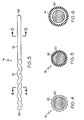
- FIGURE 3 is a straightened side-elevational view of the working portion of the medical guidewire of Figure 1;
- FIGURE 4 is a cross-sectional view of the first segment of the working portion of the medical guidewire of Figure 3 taken along lines 4-4 of Figure 3;
- FIGURE 5 is a cross-sectional view of the second segment of the working portion of the medical guidewire of Figure 3 taken along lines 5-5 of Figure 3;
- FIGURE 6 is a cross-sectional view of the guidewire structure of Figure 1 taken along lines 6-6 of Figure 1 showing the overtube surrounding a leg of the medical guidewire;
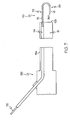
- FIGURE 7 is a schematic side-elevational cutaway view of a second embodiment of a medical instrument having a catheter and employing an alternate embodiment of a guidewire structure of the invention, wherein the guidewire structure has a medical guidewire and an overtube, wherein the medical guidewire has the working portion of Figure 3 and is employed as a non-loop-track guidewire, wherein a shortened view of the entire working portion of the medical guidewire is shown extending beyond the distal end of the catheter, and wherein the overtube has been pulled to slidingly expose a first segment of the medical guidewire; and
- FIGURE 8 is a view as in Figure 7 but previous in time to Figure 7, wherein the overtube has been pushed to slidingly cover the first segment of the medical guidewire before the covered first segment was extended beyond the distal end of the catheter.
- FIG. 1 An embodiment of a guidewire structure 10 of the invention is shown in Figures 1-6.
- a first expression of the guidewire structure 10 of the embodiment of Figures 1-6 includes a medical guidewire 12 and an overtube 14.
- the medical guidewire 12 includes a first segment 16 and a lengthwise-adjoining second segment 18.
- the overtube 14 is adapted to slidably cover the first segment 16 (as shown in Figure 2) and to slidably expose the first segment (as shown in Figure 1).
- a minimum force required to slide the exposed first segment 16 over patient tissue is greater than a minimum force required to slide the covered first segment 16 over the patient tissue.
- the exposed first segment 16 when slidingly pushed over patient tissue sticks more to the patient tissue than does the covered first segment 16 when likewise slidingly pushed over the patient tissue.
- a minimum force required to slide the exposed first segment 16 over the patient tissue is greater than a minimum force required to slide the (exposed) second segment 18 over the patient tissue.
- the exposed first segment when slidingly pushed over the patient tissue sticks more to the patient tissue than does the (exposed) second segment 18 when likewise slidingly pushed over the patient tissue.
- the overtube 14 is flexible.
- the medical guidewire 12 is resiliently flexible.
- each of the first and second segments 16 and 18 is resiliently flexible.
- the first segment 16 includes a first length of a core wire 20 and a mesh 22 surrounding, and attached to, the first length of the core wire 20.
- the mesh 22 is attached to the first length of the core wire 20 by an adhesive.
- a thin wall sleeve surrounds the mesh and is crimped against the core wire to trap the mesh between the sleeve and the core wire.
- a heat shrinkable material surrounds the mesh and is heat shrunk against the core wire to trap the mesh between the sleeve and the core wire. Other methods are left to the artisan.
- the core wire 20 consists essentially of a monolithic length of a super-elastic alloy such as nitinol available from Nitinol Devices & Components (Fremont, CA).
- the mesh 22 consists essentially of polypropylene such as Gynemesh ® surgical mesh available from Johnson & Johnson Corporation (New Brunswick, NJ).
- the overtube 14 is a lubricious overtube such as one consisting essentially of Polytetrafluoroethylene (PTFE), such as Teflon ® PTFE available from Zeus, Inc (Orangeburg, SC). It is noted that the mesh 22 sticks to patient tissue more than does the overtube 14.
- PTFE Polytetrafluoroethylene
- the first segment has a shape (such as a corrugated shape), a texture, a surface roughness (such as that of a pitted or sandblasted surface), or a series of projections (such as bristles) that tend to grip onto tissue.
- a shape such as a corrugated shape
- a texture such as that of a pitted or sandblasted surface
- a surface roughness such as that of a pitted or sandblasted surface
- a series of projections such as bristles
- the second segment 18 consists essentially of a second length of the core wire 20 and a lubricious sleeve 24 surrounding, and attached to, the second length of the core wire 20.
- the first and second lengths are portions of a monolithic length of the core wire 20.
- materials for the lubricious sleeve 24 include, without limitation, Polytetrafluoroethylene (PTFE), such as Striped Teflon ® PTFE available from Zeus, Inc (Orangeburg, SC).
- PTFE Polytetrafluoroethylene
- the lubricious sleeve 24 is applied over the second length of the core wire 20 through a heat-shrink process well known in the art. It is noted that the mesh 22 sticks to patient tissue more than does the lubricious sleeve 24.
- a second expression of the guidewire structure 10 of the embodiment of Figures 1-6 includes a medical guidewire 12 and an overtube 14.
- the medical guidewire 12 includes a working portion 26 which is extendable beyond a distal end 28 of a medical instrument 30.
- the working portion 26 includes a first segment 16 and a lengthwise-adjoining second segment 18.
- the overtube 14 surrounds the medical guidewire 12 and is adapted to slidably cover the first segment 16 (as shown in Figure 2) and to slidably expose the first segment (as shown in Figure 1).
- a minimum force required to slide the exposed first segment 16 over patient tissue is greater than a minimum force required to slide the covered first segment 16 over the patient tissue.
- the working portion 26 is a maximum portion of the medical guidewire 12 which can be extended beyond the distal end 28 of the medical instrument 30. Some applications of the guidewire structure 10 may require the entire working portion 26 to be extended beyond the distal end 28 while other applications may require less than the entire working portion 26 to be extended beyond the distal end 28. It is also noted that in some applications, the medical guidewire 12 is manually pushed (as intended by Figures 1 and 2) to extend at least some of the working portion 26 beyond the distal end 28, that in other applications a hand crank (not shown) is used to extend at least some of the working portion 26, and that in still other applications a motor (not shown) is used to extend at least some of the working portion 26. It is further noted that the examples, enablements, constructions, etc. of the first expression of the embodiment of Figures 1-6 are equally applicable to the second expression of the embodiment of Figures 1-6.
- the medical instrument 30 is an endoscope 32 having a flexible insertion tube 34.
- the distal end 28 of the medical instrument is a distal end 28' of the insertion tube 34.
- the working portion 26 is extendable beyond the distal end 28' of the insertion tube 34 from within the insertion tube 34.
- the working portion 26 is extendable as a loop track (as shown in Figures 1 and 2) beyond the distal end 28' of the insertion tube 34.
- the length of the working portion 26 is a loop-track length of the working portion 26.
- the loop-track length of the working portion 26 is at least six feet, and the working portion 26 has a substantially circular cross-section having a maximum diameter which is always less than 0.050-inch and a minimum diameter which is always at least 0.010-inch.
- the working portion 26 extends as a loop track
- the medical guidewire 12 includes a first leg 12' monolithically attached to and extending from a first end 36 of the working portion 26 (which is a proximal end of the second segment 18) proximally through a first passageway of the insertion tube 34 and outside the endoscope 32
- the medical guidewire 12 includes a second leg 12" monolithically attached to and extending from a second end 38 of the working portion 14 (which is a proximal end of the first segment 16) proximally through a second passageway of the insertion tube 34 and outside the endoscope 32.
- first and second legs 12' and 12" extend through a single passageway such as a working channel of the insertion tube.
- the loop track extends beyond the distal end of the insertion tube from outside the exterior surface of the insertion tube with the first and/or second legs engaged by guide ways on the exterior surface of the insertion tube. Other arrangements are left to the artisan.
- a guidewire structure 110 in a second deployment (shown in the alternate embodiment of Figures 7-8), includes a medical guidewire 112 having the working portion 26 shown in Figure 3, but the guidewire structure 110 is employed as a non-loop-track in a different endoscope 132 having an insertion tube 134.
- the second segment 18 has a free end 36' which extends beyond the distal end 128 of the insertion tube 134 when the working portion 26 is extended beyond the distal end 128 of the insertion tube 134
- the first segment 16 is exposed in Figure 7 and is covered by the overtube 114 in Figure 8.
- the working portion of the medical guidewire consists essentially of the first segment.
- the working portion is a loop-track working portion.
- the working portion is a non-loop-track working portion.
- a method of the invention is for using a guidewire structure 10.
- the guidewire structure 10 includes a working portion 26 which is extendable beyond a distal end 28' of an insertion tube 34 of an endoscope 32, wherein the working portion 26 includes a medical guidewire 12 and an overtube 14.
- the medical guidewire 12 includes a first segment 16 and a lengthwise-adjoining second segment 18.
- the overtube 14 is adapted to slidably cover the first segment 16 and to slidably expose the first segment 16.
- a minimum force required to slide the exposed first segment 16 over patient tissue is greater than a minimum force required to slide the covered first segment 16 over the patient tissue, and a minimum force required to slide the exposed first segment 16 over the patient tissue is greater than a minimum force required to slide the second segment 18 over the patient tissue.
- the method includes steps a) through e).
- Step a) includes inserting the distal end 28' of the insertion tube 34 an initial distance into a body lumen of a patient.
- Step b) includes extending at least a portion of the second segment 18 beyond the distal end 28' of the insertion tube 34.
- Step c) includes extending at least a portion of the first segment 16 beyond the distal end 28' of the insertion tube 34 with the overtube 14 covering the extended first segment 16.
- Step d) includes sliding the overtube 14 off the extended first segment 16 exposing the extended first segment 16.
- Step e) includes advancing the insertion tube 34 along the exposed and extended first segment 16 further into the body lumen of the patient.
- step c) includes manually pulling the overtube 14 slidingly off the extended first segment 16.
- step c) includes using a motor to pull the overtube slidingly off the extended first segment.
- having a "non-sticky" overtube and having a loop-track or non-loop-track medical guidewire including a "sticky" first segment which can be slidably covered and slidably exposed by the overtube is expected to allow easier extension of the covered first segment in a body lumen of a patient followed by improved anchoring of the uncovered first segment against patient tissue resulting in improved advancement of an endoscope insertion tube along the anchored uncovered first segment.
Landscapes
- Health & Medical Sciences (AREA)
- Life Sciences & Earth Sciences (AREA)
- Veterinary Medicine (AREA)
- Biophysics (AREA)
- Engineering & Computer Science (AREA)
- Surgery (AREA)
- Biomedical Technology (AREA)
- Heart & Thoracic Surgery (AREA)
- Public Health (AREA)
- Animal Behavior & Ethology (AREA)
- General Health & Medical Sciences (AREA)
- Gastroenterology & Hepatology (AREA)
- Pulmonology (AREA)
- Physics & Mathematics (AREA)
- Hematology (AREA)
- Nuclear Medicine, Radiotherapy & Molecular Imaging (AREA)
- Optics & Photonics (AREA)
- Pathology (AREA)
- Radiology & Medical Imaging (AREA)
- Anesthesiology (AREA)
- Medical Informatics (AREA)
- Molecular Biology (AREA)
- Media Introduction/Drainage Providing Device (AREA)
- Endoscopes (AREA)
Abstract
Description
- Field of the Invention
- The present invention is related generally to guidewire structures, and more particularly to a guidewire structure having a medical guidewire.
- Background of the Invention
- A physician typically accesses and visualizes tissue within a patient's gastrointestinal (GI) tract with an endoscope (such as a gastroscope or a colonoscope) having a long, flexible insertion tube. For the upper GI, a physician may insert a gastroscope into the sedated patient's mouth to examine and treat tissue in the esophagus, stomach, and proximal duodenum. For the lower GI, a physician may insert a colonoscope through the sedated patient's anus to examine the rectum and colon. Some endoscopes have a working channel in the insertion tube, typically about 2.5-3.5 millimeters in diameter, extending from a port in the handpiece to the distal portion of the insertion tube. A physician may insert medical devices into the working channel to help diagnose or treat tissue within the patient.
- Guidewires have been used to aid the introduction of catheters (such as insertion tubes of endoscopes) and other instruments into many sites in the human body. Many medical applications and specific designs of guidewires have been for cardiovascular use. There are, however, specific challenges relating to the use of guidewires in the GI tract, as opposed to the vascular system. Thus, the bowel is more tortuous, softer and generally of larger diameter. Furthermore, in the case of the small intestine and the colon, these are longer than most arteries or veins.
- Still, scientists and engineers continue to seek improved guidewire structures having a medical guidewire.
- Summary
- A first expression of an embodiment of a guidewire structure of the invention includes a medical guidewire and an overtube. The medical guidewire includes a first segment and a lengthwise-adjoining second segment. The overtube is adapted to slidably cover the first segment and to slidably expose the first segment. A minimum force required to slide the exposed first segment over patient tissue is greater than a minimum force required to slide the covered first segment over the patient tissue.
- A second expression of an embodiment of a guidewire structure of the invention includes a medical guidewire and an overtube. The medical guidewire includes a working portion which is extendable beyond a distal end of a medical instrument. The working portion includes a first segment and a lengthwise-adjoining second segment. The overtube surrounds the medical guidewire and is adapted to slidably cover the first segment and to slidably expose the first segment. A minimum force required to slide the exposed first segment over patient tissue is greater than a minimum force required to slide the covered first segment over the patient tissue.
- A method of the invention is for using a guidewire structure. The guidewire structure includes a medical guidewire and an overtube. The medical guidewire includes a working portion which is extendable beyond a distal end of an insertion tube of an endoscope, wherein the working portion includes a first segment and a lengthwise-adjoining second segment. The overtube is adapted to slidably cover the first segment and to slidably expose the first segment. A minimum force required to slide the exposed first segment over patient tissue is greater than a minimum force required to slide the covered first segment over the patient tissue, and a minimum force required to slide the exposed first segment over the patient tissue is greater than a minimum force required to slide the second segment over the patient tissue. The method includes inserting the distal end of the insertion tube an initial distance into a body lumen of a patient. The method also includes extending at least a portion of the second segment beyond the distal end of the insertion tube. The method also includes extending at least a portion of the first segment beyond the distal end of the insertion tube with the overtube covering the extended first segment. The method also includes sliding the overtube off the extended first segment exposing the extended first segment. The method also includes advancing the insertion tube along the exposed and extended first segment further into the body lumen of the patient.
- Several benefits and advantages are obtained from one or more of the expressions of an embodiment and the method of the invention. In one example, having a "non-sticky" overtube and having a loop-track or non-loop-track medical guidewire including a "sticky" first segment which can be slidably covered and slidably exposed by the overtube is expected to allow easier extension of the covered first segment in a body lumen of a patient followed by improved anchoring of the uncovered first segment against patient tissue resulting in improved advancement of an endoscope insertion tube along the anchored uncovered first segment.
- Brief Description of the Figures
- FIGURE 1 is a schematic side-elevational cutaway view of a first embodiment of a medical instrument having a catheter and employing an embodiment of a guidewire structure of the invention, wherein the guidewire structure has a medical guidewire and an overtube, wherein the medical guidewire is employed as a loop-track guidewire, wherein a shortened view of the entire working portion of the medical guidewire is shown extending beyond the distal end of the catheter, and wherein the overtube has been pulled to slidingly expose a first segment of the medical guidewire;
- FIGURE 2 is a view as in Figure 1 but previous in time to Figure 1, wherein the overtube has been pushed to slidingly cover the first segment of the medical guidewire before the covered first segment was extended beyond the distal end of the catheter;
- FIGURE 3 is a straightened side-elevational view of the working portion of the medical guidewire of Figure 1;
- FIGURE 4 is a cross-sectional view of the first segment of the working portion of the medical guidewire of Figure 3 taken along lines 4-4 of Figure 3;
- FIGURE 5 is a cross-sectional view of the second segment of the working portion of the medical guidewire of Figure 3 taken along lines 5-5 of Figure 3;
- FIGURE 6 is a cross-sectional view of the guidewire structure of Figure 1 taken along lines 6-6 of Figure 1 showing the overtube surrounding a leg of the medical guidewire;
- FIGURE 7 is a schematic side-elevational cutaway view of a second embodiment of a medical instrument having a catheter and employing an alternate embodiment of a guidewire structure of the invention, wherein the guidewire structure has a medical guidewire and an overtube, wherein the medical guidewire has the working portion of Figure 3 and is employed as a non-loop-track guidewire, wherein a shortened view of the entire working portion of the medical guidewire is shown extending beyond the distal end of the catheter, and wherein the overtube has been pulled to slidingly expose a first segment of the medical guidewire; and
- FIGURE 8 is a view as in Figure 7 but previous in time to Figure 7, wherein the overtube has been pushed to slidingly cover the first segment of the medical guidewire before the covered first segment was extended beyond the distal end of the catheter.
- Detailed Description
- Before explaining the several embodiments of the present invention in detail, it should be noted that each embodiment is not limited in its application or use to the details of construction and arrangement of parts and steps illustrated in the accompanying drawings and description. The illustrative embodiments of the invention may be implemented or incorporated in other embodiments, variations and modifications, and may be practiced or carried out in various ways. Furthermore, unless otherwise indicated, the terms and expressions employed herein have been chosen for the purpose of describing the illustrative embodiments of the present invention for the convenience of the reader and are not for the purpose of limiting the invention.
- It is further understood that any one or more of the following-described embodiments, examples, etc. can be combined with any one or more of the other following-described embodiments, examples, etc.
- An embodiment of a
guidewire structure 10 of the invention is shown in Figures 1-6. A first expression of theguidewire structure 10 of the embodiment of Figures 1-6 includes amedical guidewire 12 and anovertube 14. Themedical guidewire 12 includes afirst segment 16 and a lengthwise-adjoiningsecond segment 18. Theovertube 14 is adapted to slidably cover the first segment 16 (as shown in Figure 2) and to slidably expose the first segment (as shown in Figure 1). A minimum force required to slide the exposedfirst segment 16 over patient tissue is greater than a minimum force required to slide the coveredfirst segment 16 over the patient tissue. - It is noted that the exposed
first segment 16 when slidingly pushed over patient tissue sticks more to the patient tissue than does the coveredfirst segment 16 when likewise slidingly pushed over the patient tissue. In one example, a minimum force required to slide the exposedfirst segment 16 over the patient tissue is greater than a minimum force required to slide the (exposed)second segment 18 over the patient tissue. It is also noted that the exposed first segment when slidingly pushed over the patient tissue sticks more to the patient tissue than does the (exposed)second segment 18 when likewise slidingly pushed over the patient tissue. - In one enablement of the first expression of the embodiment of Figures 1-6, the
overtube 14 is flexible. In one variation, themedical guidewire 12 is resiliently flexible. In one modification, each of the first andsecond segments - In one construction of the first expression of the embodiment of Figures 1-6, the
first segment 16 includes a first length of acore wire 20 and amesh 22 surrounding, and attached to, the first length of thecore wire 20. In one method, themesh 22 is attached to the first length of thecore wire 20 by an adhesive. In another method, not shown, a thin wall sleeve surrounds the mesh and is crimped against the core wire to trap the mesh between the sleeve and the core wire. In a further method, a heat shrinkable material surrounds the mesh and is heat shrunk against the core wire to trap the mesh between the sleeve and the core wire. Other methods are left to the artisan. In one example, thecore wire 20 consists essentially of a monolithic length of a super-elastic alloy such as nitinol available from Nitinol Devices & Components (Fremont, CA). In the same or a different example, themesh 22 consists essentially of polypropylene such as Gynemesh® surgical mesh available from Johnson & Johnson Corporation (New Brunswick, NJ). In the same or a different example, theovertube 14 is a lubricious overtube such as one consisting essentially of Polytetrafluoroethylene (PTFE), such as Teflon® PTFE available from Zeus, Inc (Orangeburg, SC). It is noted that themesh 22 sticks to patient tissue more than does theovertube 14. In non-mesh constructions, not shown, the first segment has a shape (such as a corrugated shape), a texture, a surface roughness (such as that of a pitted or sandblasted surface), or a series of projections (such as bristles) that tend to grip onto tissue. - In the same or a different construction, the
second segment 18 consists essentially of a second length of thecore wire 20 and alubricious sleeve 24 surrounding, and attached to, the second length of thecore wire 20. In one variation, the first and second lengths are portions of a monolithic length of thecore wire 20. Examples of materials for thelubricious sleeve 24 include, without limitation, Polytetrafluoroethylene (PTFE), such as Striped Teflon® PTFE available from Zeus, Inc (Orangeburg, SC). In one method, thelubricious sleeve 24 is applied over the second length of thecore wire 20 through a heat-shrink process well known in the art. It is noted that themesh 22 sticks to patient tissue more than does thelubricious sleeve 24. - A second expression of the
guidewire structure 10 of the embodiment of Figures 1-6 includes amedical guidewire 12 and anovertube 14. Themedical guidewire 12 includes a workingportion 26 which is extendable beyond adistal end 28 of amedical instrument 30. The workingportion 26 includes afirst segment 16 and a lengthwise-adjoiningsecond segment 18. Theovertube 14 surrounds themedical guidewire 12 and is adapted to slidably cover the first segment 16 (as shown in Figure 2) and to slidably expose the first segment (as shown in Figure 1). A minimum force required to slide the exposedfirst segment 16 over patient tissue is greater than a minimum force required to slide the coveredfirst segment 16 over the patient tissue. - It is noted that the working
portion 26 is a maximum portion of themedical guidewire 12 which can be extended beyond thedistal end 28 of themedical instrument 30. Some applications of theguidewire structure 10 may require the entire workingportion 26 to be extended beyond thedistal end 28 while other applications may require less than the entire workingportion 26 to be extended beyond thedistal end 28. It is also noted that in some applications, themedical guidewire 12 is manually pushed (as intended by Figures 1 and 2) to extend at least some of the workingportion 26 beyond thedistal end 28, that in other applications a hand crank (not shown) is used to extend at least some of the workingportion 26, and that in still other applications a motor (not shown) is used to extend at least some of the workingportion 26. It is further noted that the examples, enablements, constructions, etc. of the first expression of the embodiment of Figures 1-6 are equally applicable to the second expression of the embodiment of Figures 1-6. - In one application of the second expression of the embodiment of Figures 1-6, the
medical instrument 30 is anendoscope 32 having aflexible insertion tube 34. In this application, thedistal end 28 of the medical instrument is a distal end 28' of theinsertion tube 34. In one variation, the workingportion 26 is extendable beyond the distal end 28' of theinsertion tube 34 from within theinsertion tube 34. - In a first deployment of the second expression of the embodiment of Figures 1-6, the working
portion 26 is extendable as a loop track (as shown in Figures 1 and 2) beyond the distal end 28' of theinsertion tube 34. Here, the length of the workingportion 26 is a loop-track length of the workingportion 26. In one construction, the loop-track length of the workingportion 26 is at least six feet, and the workingportion 26 has a substantially circular cross-section having a maximum diameter which is always less than 0.050-inch and a minimum diameter which is always at least 0.010-inch. - In a first arrangement of the second expression of the embodiment of Figures 1-6, the working
portion 26 extends as a loop track, themedical guidewire 12 includes a first leg 12' monolithically attached to and extending from afirst end 36 of the working portion 26 (which is a proximal end of the second segment 18) proximally through a first passageway of theinsertion tube 34 and outside theendoscope 32, and themedical guidewire 12 includes asecond leg 12" monolithically attached to and extending from asecond end 38 of the working portion 14 (which is a proximal end of the first segment 16) proximally through a second passageway of theinsertion tube 34 and outside theendoscope 32. In a second arrangement, not shown, the first andsecond legs 12' and 12" extend through a single passageway such as a working channel of the insertion tube. In a third arrangement, not shown, the loop track extends beyond the distal end of the insertion tube from outside the exterior surface of the insertion tube with the first and/or second legs engaged by guide ways on the exterior surface of the insertion tube. Other arrangements are left to the artisan. - In a second deployment (shown in the alternate embodiment of Figures 7-8), a
guidewire structure 110 includes amedical guidewire 112 having the workingportion 26 shown in Figure 3, but theguidewire structure 110 is employed as a non-loop-track in adifferent endoscope 132 having aninsertion tube 134. Here, thesecond segment 18 has a free end 36' which extends beyond thedistal end 128 of theinsertion tube 134 when the workingportion 26 is extended beyond thedistal end 128 of theinsertion tube 134 Thefirst segment 16 is exposed in Figure 7 and is covered by theovertube 114 in Figure 8. - In a different embodiment of the guidewire structure, not shown, the working portion of the medical guidewire consists essentially of the first segment. In one deployment, the working portion is a loop-track working portion. In a different deployment, the working portion is a non-loop-track working portion.
- A method of the invention is for using a
guidewire structure 10. Theguidewire structure 10 includes a workingportion 26 which is extendable beyond a distal end 28' of aninsertion tube 34 of anendoscope 32, wherein the workingportion 26 includes amedical guidewire 12 and anovertube 14. Themedical guidewire 12 includes afirst segment 16 and a lengthwise-adjoiningsecond segment 18. Theovertube 14 is adapted to slidably cover thefirst segment 16 and to slidably expose thefirst segment 16. A minimum force required to slide the exposedfirst segment 16 over patient tissue is greater than a minimum force required to slide the coveredfirst segment 16 over the patient tissue, and a minimum force required to slide the exposedfirst segment 16 over the patient tissue is greater than a minimum force required to slide thesecond segment 18 over the patient tissue. The method includes steps a) through e). Step a) includes inserting the distal end 28' of theinsertion tube 34 an initial distance into a body lumen of a patient. Step b) includes extending at least a portion of thesecond segment 18 beyond the distal end 28' of theinsertion tube 34. Step c) includes extending at least a portion of thefirst segment 16 beyond the distal end 28' of theinsertion tube 34 with theovertube 14 covering the extendedfirst segment 16. Step d) includes sliding theovertube 14 off the extendedfirst segment 16 exposing the extendedfirst segment 16. Step e) includes advancing theinsertion tube 34 along the exposed and extendedfirst segment 16 further into the body lumen of the patient. - In one implementation of the method, step c) includes manually pulling the
overtube 14 slidingly off the extendedfirst segment 16. In a different implementation, step c) includes using a motor to pull the overtube slidingly off the extended first segment. - Several benefits and advantages are obtained from one or more of the embodiments and the method of the invention. In one example, having a "non-sticky" overtube and having a loop-track or non-loop-track medical guidewire including a "sticky" first segment which can be slidably covered and slidably exposed by the overtube is expected to allow easier extension of the covered first segment in a body lumen of a patient followed by improved anchoring of the uncovered first segment against patient tissue resulting in improved advancement of an endoscope insertion tube along the anchored uncovered first segment.
- While the present invention has been illustrated by descriptions of a method, several expressions of embodiments, and examples, etc. thereof, it is not the intention of the applicants to restrict or limit the spirit and scope of the appended claims to such detail. Numerous other variations, changes, and substitutions will occur to those skilled in the art without departing from the scope of the invention. It will be understood that the foregoing description is provided by way of example, and that other modifications may occur to those skilled in the art without departing from the scope and spirit of the appended Claims.
Claims (11)
- A guidewire structure comprising a medical guidewire and an overtube, wherein the medical guidewire includes a first segment and a lengthwise-adjoining second segment, wherein the overtube is adapted to slidably cover the first segment and to slidably expose the first segment, and wherein a minimum force required to slide the exposed first segment over patient tissue is greater than a minimum force required to slide the covered first segment over the patient tissue.
- The guidewire structure of claim 1, wherein a minimum force required to slide the exposed first segment over the patient tissue is greater than a minimum force required to slide the second segment over the patient tissue.
- The guidewire structure of claim 2, wherein the first segment includes a first length of a core wire and a mesh surrounding, and attached to, the first length of the core wire.
- The guidewire structure of claim 3, wherein the first length of the core wire consists essentially of nitinol and wherein the mesh consists essentially of polypropylene.
- The guidewire structure of claim 3, wherein the overtube is a lubricious overtube.
- The guidewire structure of claim 3, wherein the second segment consists essentially of a second length of the core wire and a lubricious sleeve surrounding, and attached to, the second length of the core wire.
- The guidewire structure of claim 6, wherein the overtube is a lubricious overtube.
- A guidewire structure comprising a medical guidewire and an overtube, wherein the medical guidewire includes a working portion which is extendable beyond a distal end of a medical instrument, wherein the working portion includes a first segment and a lengthwise-adjoining second segment, wherein the overtube surrounds the medical guidewire and is adapted to slidably cover the first segment and to slidably expose the first segment, and wherein a minimum force required to slide the exposed first segment over patient tissue is greater than a minimum force required to slide the covered first segment over the patient tissue.
- The guidewire structure of claim 8, wherein the medical instrument is an endoscope having a flexible insertion tube, wherein the distal end of the medical instrument is a distal end of the insertion tube and wherein the working portion is extendable beyond the distal end of the insertion tube from within the insertion tube.
- The guidewire structure of claim 9, wherein the working portion is extendable as a loop-track beyond the distal end of the insertion tube.
- The guidewire structure of claim 9, wherein the second segment has a free end which extends beyond the distal end of the insertion tube when the working portion is extended beyond the distal end of the insertion tube.
Applications Claiming Priority (1)
| Application Number | Priority Date | Filing Date | Title |
|---|---|---|---|
| US11/515,939 US20080097331A1 (en) | 2006-09-05 | 2006-09-05 | Guidewire structure including a medical guidewire and method for using |
Publications (2)
| Publication Number | Publication Date |
|---|---|
| EP1897583A1 true EP1897583A1 (en) | 2008-03-12 |
| EP1897583B1 EP1897583B1 (en) | 2010-08-04 |
Family
ID=38787573
Family Applications (1)
| Application Number | Title | Priority Date | Filing Date |
|---|---|---|---|
| EP07253495A Not-in-force EP1897583B1 (en) | 2006-09-05 | 2007-09-04 | Guidewire structure including a medical guidewire |
Country Status (7)
| Country | Link |
|---|---|
| US (1) | US20080097331A1 (en) |
| EP (1) | EP1897583B1 (en) |
| JP (1) | JP2008068083A (en) |
| CN (1) | CN101138485A (en) |
| AU (1) | AU2007214281A1 (en) |
| CA (1) | CA2600173A1 (en) |
| DE (1) | DE602007008179D1 (en) |
Families Citing this family (3)
| Publication number | Priority date | Publication date | Assignee | Title |
|---|---|---|---|---|
| US8175962B2 (en) * | 2008-12-18 | 2012-05-08 | Metabank | Computerized extension of credit to existing demand deposit accounts, prepaid cards and lines of credit based on expected tax refund proceeds, associated systems and computer program products |
| US8409169B1 (en) * | 2009-06-18 | 2013-04-02 | Gerald Moss | Catheter and method of making the same |
| JP2012065871A (en) | 2010-09-24 | 2012-04-05 | Nihon Covidien Kk | Guidewire insertion aid |
Citations (5)
| Publication number | Priority date | Publication date | Assignee | Title |
|---|---|---|---|---|
| US20020156454A1 (en) * | 1997-12-12 | 2002-10-24 | Boris Reydel | Body canal intrusion instrumentation having bi-directional coefficient of surface friction with body tissue |
| FR2850285A1 (en) * | 2002-01-24 | 2004-07-30 | Medtronic Vascular Inc | Guide wire apparatus for temporary distal embolic protection in minimally invasive procedures has tubular protection element which has longer length in collapsed configuration than in expanded configuration |
| US20050101836A1 (en) * | 2000-05-30 | 2005-05-12 | Olympus Optical Co., Ltd. | Medical guide wire |
| EP1559361A2 (en) * | 2004-01-30 | 2005-08-03 | Fujinon Corporation | Endoscope applicator and endoscope apparatus |
| US20050256429A1 (en) * | 2004-05-14 | 2005-11-17 | Ethicon Endo-Surgery, Inc. | Guidewire structure |
Family Cites Families (68)
| Publication number | Priority date | Publication date | Assignee | Title |
|---|---|---|---|---|
| US1891054A (en) * | 1931-03-28 | 1932-12-13 | Louis K Pitman | Surgical instrument |
| US3892228A (en) * | 1972-10-06 | 1975-07-01 | Olympus Optical Co | Apparatus for adjusting the flexing of the bending section of an endoscope |
| US4176662A (en) * | 1977-06-17 | 1979-12-04 | The United States Of America As Represented By The Administrator Of The National Aeronautics And Space Administration | Apparatus for endoscopic examination |
| US4224929A (en) * | 1977-11-08 | 1980-09-30 | Olympus Optical Co., Ltd. | Endoscope with expansible cuff member and operation section |
| US4207872A (en) * | 1977-12-16 | 1980-06-17 | Northwestern University | Device and method for advancing an endoscope through a body passage |
| US4326530A (en) * | 1980-03-05 | 1982-04-27 | Fleury Jr George J | Surgical snare |
| US4447227A (en) * | 1982-06-09 | 1984-05-08 | Endoscopy Surgical Systems, Inc. | Multi-purpose medical devices |
| DE3504292C1 (en) * | 1985-02-08 | 1986-07-24 | Richard Wolf Gmbh, 7134 Knittlingen | Instrument for endoscopic interventions, especially for percutaneous gallstone removal or gallbladder surgery |
| US4947827A (en) * | 1988-12-30 | 1990-08-14 | Opielab, Inc. | Flexible endoscope |
| JPH0713682Y2 (en) * | 1990-02-01 | 1995-04-05 | 株式会社町田製作所 | Endoscope cover locking structure |
| US5025778A (en) * | 1990-03-26 | 1991-06-25 | Opielab, Inc. | Endoscope with potential channels and method of using the same |
| US5113872A (en) * | 1990-04-18 | 1992-05-19 | Cordis Corporation | Guidewire extension system with connectors |
| US5078716A (en) * | 1990-05-11 | 1992-01-07 | Doll Larry F | Electrosurgical apparatus for resecting abnormal protruding growth |
| US5360403A (en) * | 1990-05-16 | 1994-11-01 | Lake Region Manufacturing Co., Inc. | Balloon catheter with lumen occluder |
| US5201323A (en) * | 1991-02-20 | 1993-04-13 | Brigham & Women's Hospital | Wire-guided cytology brush |
| US5503616A (en) * | 1991-06-10 | 1996-04-02 | Endomedical Technologies, Inc. | Collapsible access channel system |
| US5217001A (en) * | 1991-12-09 | 1993-06-08 | Nakao Naomi L | Endoscope sheath and related method |
| US5555883A (en) * | 1992-02-24 | 1996-09-17 | Avitall; Boaz | Loop electrode array mapping and ablation catheter for cardiac chambers |
| EP0658090B1 (en) * | 1992-09-01 | 1998-11-04 | Edwin L. Adair | Sterilizable endoscope with separable disposable tube assembly |
| US5643175A (en) * | 1992-09-01 | 1997-07-01 | Adair; Edwin L. | Sterilizable endoscope with separable disposable tube assembly |
| US5337732A (en) * | 1992-09-16 | 1994-08-16 | Cedars-Sinai Medical Center | Robotic endoscopy |
| JPH08506259A (en) * | 1993-02-02 | 1996-07-09 | ヴィーダメッド インコーポレイテッド | Transurethral needle excision device and method |
| US5345925A (en) * | 1993-03-26 | 1994-09-13 | Welch Allyn, Inc. | Self-advancing endoscope |
| DK0625358T3 (en) * | 1993-05-19 | 1996-08-05 | Schneider Europ Ag | Wire guide |
| US5398670A (en) * | 1993-08-31 | 1995-03-21 | Ethicon, Inc. | Lumen traversing device |
| US5363847A (en) * | 1993-10-27 | 1994-11-15 | Cordis Corporation | Guidewire having double distal portions |
| US5535756A (en) * | 1994-01-06 | 1996-07-16 | Parasher; Vinod K. | Catheter with simultaneous brush cytology and scrape biopsy capability |
| IL108352A (en) * | 1994-01-17 | 2000-02-29 | Given Imaging Ltd | In vivo video camera system |
| US5645519A (en) * | 1994-03-18 | 1997-07-08 | Jai S. Lee | Endoscopic instrument for controlled introduction of tubular members in the body and methods therefor |
| US5505686A (en) * | 1994-05-05 | 1996-04-09 | Imagyn Medical, Inc. | Endoscope with protruding member and method of utilizing the same |
| US5522819A (en) * | 1994-05-12 | 1996-06-04 | Target Therapeutics, Inc. | Dual coil medical retrieval device |
| US5595565A (en) * | 1994-06-30 | 1997-01-21 | The Trustees Of Columbia University In The City Of New York | Self-propelled endoscope using pressure driven linear actuators |
| US5836947A (en) * | 1994-10-07 | 1998-11-17 | Ep Technologies, Inc. | Flexible structures having movable splines for supporting electrode elements |
| US6071274A (en) * | 1996-12-19 | 2000-06-06 | Ep Technologies, Inc. | Loop structures for supporting multiple electrode elements |
| US5749889A (en) * | 1996-02-13 | 1998-05-12 | Imagyn Medical, Inc. | Method and apparatus for performing biopsy |
| US5895417A (en) * | 1996-03-06 | 1999-04-20 | Cardiac Pathways Corporation | Deflectable loop design for a linear lesion ablation apparatus |
| US5904648A (en) * | 1996-06-18 | 1999-05-18 | Cook Incorporated | Guided endobronchial blocker catheter |
| US5882293A (en) * | 1996-09-05 | 1999-03-16 | Asahi Kogaku Kogyo Kabushiki Kaisha | Treatment accessories for endoscope |
| US6355034B2 (en) * | 1996-09-20 | 2002-03-12 | Ioan Cosmescu | Multifunctional telescopic monopolar/bipolar surgical device and method therefor |
| US5944654A (en) * | 1996-11-14 | 1999-08-31 | Vista Medical Technologies, Inc. | Endoscope with replaceable irrigation tube |
| DE19748795B4 (en) * | 1996-11-18 | 2006-08-17 | Olympus Corporation | endoscope |
| US6203525B1 (en) * | 1996-12-19 | 2001-03-20 | Ep Technologies, Inc. | Catheterdistal assembly with pull wires |
| US6007482A (en) * | 1996-12-20 | 1999-12-28 | Madni; Asad M. | Endoscope with stretchable flexible sheath covering |
| US6059719A (en) * | 1997-08-06 | 2000-05-09 | Olympus Optical Co., Ltd. | Endoscope system |
| US6238389B1 (en) * | 1997-09-30 | 2001-05-29 | Boston Scientific Corporation | Deflectable interstitial ablation device |
| US6767339B2 (en) * | 1997-12-12 | 2004-07-27 | Wilson-Cook Medical, Inc. | Body canal intrusion instrumentation having bidirectional coefficient of surface friction with body tissue |
| US5984860A (en) * | 1998-03-25 | 1999-11-16 | Shan; Yansong | Pass-through duodenal enteroscopic device |
| US6352503B1 (en) * | 1998-07-17 | 2002-03-05 | Olympus Optical Co., Ltd. | Endoscopic surgery apparatus |
| US6106488A (en) * | 1998-08-11 | 2000-08-22 | Scimed Life Systems, Inc. | Flexural rigidity profile guidewire tip |
| US6162171A (en) * | 1998-12-07 | 2000-12-19 | Wan Sing Ng | Robotic endoscope and an autonomous pipe robot for performing endoscopic procedures |
| US6190382B1 (en) * | 1998-12-14 | 2001-02-20 | Medwaves, Inc. | Radio-frequency based catheter system for ablation of body tissues |
| KR100277798B1 (en) * | 1999-01-08 | 2000-12-15 | 김순택 | Cathode ray tube |
| US6527753B2 (en) * | 2000-02-29 | 2003-03-04 | Olympus Optical Co., Ltd. | Endoscopic treatment system |
| WO2001087144A1 (en) * | 2000-05-15 | 2001-11-22 | C.R. Bard, Inc. | Endoscopic accessory attachment mechanism |
| JP4554034B2 (en) * | 2000-05-31 | 2010-09-29 | オリンパス株式会社 | Medical guidewire |
| US6309346B1 (en) * | 2000-06-29 | 2001-10-30 | Ashkan Farhadi | Creeping colonoscope |
| JP2002112946A (en) * | 2000-10-11 | 2002-04-16 | Olympus Optical Co Ltd | Hood for endoscope |
| US6569085B2 (en) * | 2001-08-16 | 2003-05-27 | Syntheon, Llc | Methods and apparatus for delivering a medical instrument over an endoscope while the endoscope is in a body lumen |
| US6997931B2 (en) * | 2001-02-02 | 2006-02-14 | Lsi Solutions, Inc. | System for endoscopic suturing |
| JP3939158B2 (en) * | 2001-02-06 | 2007-07-04 | オリンパス株式会社 | Endoscope device |
| JP3722729B2 (en) * | 2001-06-04 | 2005-11-30 | オリンパス株式会社 | Endoscope treatment device |
| US6740030B2 (en) * | 2002-01-04 | 2004-05-25 | Vision Sciences, Inc. | Endoscope assemblies having working channels with reduced bending and stretching resistance |
| US7261728B2 (en) * | 2002-03-15 | 2007-08-28 | Ethicon Endo-Surgery, Inc. | Biopsy forceps device and method |
| US7226410B2 (en) * | 2002-12-05 | 2007-06-05 | Ethicon-Endo Surgery, Inc. | Locally-propelled, intraluminal device with cable loop track and method of use |
| US7351202B2 (en) * | 2002-12-05 | 2008-04-01 | Ethicon Endo-Surgery, Inc. | Medical device with track and method of use |
| GB0307715D0 (en) * | 2003-04-03 | 2003-05-07 | Ethicon Endo Surgery Inc | Guide wire structure for insertion into an internal space |
| US7431694B2 (en) * | 2003-05-16 | 2008-10-07 | Ethicon Endo-Surgery, Inc. | Method of guiding medical devices |
| US7785269B2 (en) * | 2004-05-14 | 2010-08-31 | Ethicon Endo-Surgery, Inc. | Medical instrument having a guidewire and an add-to catheter |
-
2006
- 2006-09-05 US US11/515,939 patent/US20080097331A1/en not_active Abandoned
-
2007
- 2007-08-28 AU AU2007214281A patent/AU2007214281A1/en not_active Abandoned
- 2007-09-04 CA CA002600173A patent/CA2600173A1/en not_active Abandoned
- 2007-09-04 DE DE602007008179T patent/DE602007008179D1/en active Active
- 2007-09-04 EP EP07253495A patent/EP1897583B1/en not_active Not-in-force
- 2007-09-04 JP JP2007229317A patent/JP2008068083A/en not_active Ceased
- 2007-09-05 CN CNA2007101526546A patent/CN101138485A/en active Pending
Patent Citations (5)
| Publication number | Priority date | Publication date | Assignee | Title |
|---|---|---|---|---|
| US20020156454A1 (en) * | 1997-12-12 | 2002-10-24 | Boris Reydel | Body canal intrusion instrumentation having bi-directional coefficient of surface friction with body tissue |
| US20050101836A1 (en) * | 2000-05-30 | 2005-05-12 | Olympus Optical Co., Ltd. | Medical guide wire |
| FR2850285A1 (en) * | 2002-01-24 | 2004-07-30 | Medtronic Vascular Inc | Guide wire apparatus for temporary distal embolic protection in minimally invasive procedures has tubular protection element which has longer length in collapsed configuration than in expanded configuration |
| EP1559361A2 (en) * | 2004-01-30 | 2005-08-03 | Fujinon Corporation | Endoscope applicator and endoscope apparatus |
| US20050256429A1 (en) * | 2004-05-14 | 2005-11-17 | Ethicon Endo-Surgery, Inc. | Guidewire structure |
Also Published As
| Publication number | Publication date |
|---|---|
| US20080097331A1 (en) | 2008-04-24 |
| CA2600173A1 (en) | 2008-03-05 |
| AU2007214281A1 (en) | 2008-03-20 |
| DE602007008179D1 (en) | 2010-09-16 |
| CN101138485A (en) | 2008-03-12 |
| JP2008068083A (en) | 2008-03-27 |
| EP1897583B1 (en) | 2010-08-04 |
Similar Documents
| Publication | Publication Date | Title |
|---|---|---|
| WO2008022262A1 (en) | Guidewire structure including a medical guidewire | |
| US7896862B2 (en) | Medical instrument having a controlled guidewire drive | |
| US7785269B2 (en) | Medical instrument having a guidewire and an add-to catheter | |
| CA2784097C (en) | Endoscope cap with ramp | |
| US20110257477A1 (en) | Endoscopic Mucosal Resection (EMR) Over-Sheath and Methods | |
| EP2061545B1 (en) | Medical instrument | |
| EP1897583B1 (en) | Guidewire structure including a medical guidewire |
Legal Events
| Date | Code | Title | Description |
|---|---|---|---|
| PUAI | Public reference made under article 153(3) epc to a published international application that has entered the european phase |
Free format text: ORIGINAL CODE: 0009012 |
|
| AK | Designated contracting states |
Kind code of ref document: A1 Designated state(s): AT BE BG CH CY CZ DE DK EE ES FI FR GB GR HU IE IS IT LI LT LU LV MC MT NL PL PT RO SE SI SK TR |
|
| AX | Request for extension of the european patent |
Extension state: AL BA HR MK YU |
|
| 17P | Request for examination filed |
Effective date: 20080910 |
|
| 17Q | First examination report despatched |
Effective date: 20081010 |
|
| AKX | Designation fees paid |
Designated state(s): DE ES FR GB IT |
|
| GRAP | Despatch of communication of intention to grant a patent |
Free format text: ORIGINAL CODE: EPIDOSNIGR1 |
|
| RTI1 | Title (correction) |
Free format text: GUIDEWIRE STRUCTURE INCLUDING A MEDICAL GUIDEWIRE |
|
| GRAS | Grant fee paid |
Free format text: ORIGINAL CODE: EPIDOSNIGR3 |
|
| GRAA | (expected) grant |
Free format text: ORIGINAL CODE: 0009210 |
|
| AK | Designated contracting states |
Kind code of ref document: B1 Designated state(s): DE ES FR GB IT |
|
| REG | Reference to a national code |
Ref country code: GB Ref legal event code: FG4D |
|
| REF | Corresponds to: |
Ref document number: 602007008179 Country of ref document: DE Date of ref document: 20100916 Kind code of ref document: P |
|
| PG25 | Lapsed in a contracting state [announced via postgrant information from national office to epo] |
Ref country code: IT Free format text: LAPSE BECAUSE OF FAILURE TO SUBMIT A TRANSLATION OF THE DESCRIPTION OR TO PAY THE FEE WITHIN THE PRESCRIBED TIME-LIMIT Effective date: 20100804 |
|
| PLBE | No opposition filed within time limit |
Free format text: ORIGINAL CODE: 0009261 |
|
| STAA | Information on the status of an ep patent application or granted ep patent |
Free format text: STATUS: NO OPPOSITION FILED WITHIN TIME LIMIT |
|
| REG | Reference to a national code |
Ref country code: FR Ref legal event code: ST Effective date: 20110531 |
|
| PG25 | Lapsed in a contracting state [announced via postgrant information from national office to epo] |
Ref country code: ES Free format text: LAPSE BECAUSE OF FAILURE TO SUBMIT A TRANSLATION OF THE DESCRIPTION OR TO PAY THE FEE WITHIN THE PRESCRIBED TIME-LIMIT Effective date: 20101115 |
|
| 26N | No opposition filed |
Effective date: 20110506 |
|
| REG | Reference to a national code |
Ref country code: DE Ref legal event code: R119 Ref document number: 602007008179 Country of ref document: DE Effective date: 20110401 |
|
| PG25 | Lapsed in a contracting state [announced via postgrant information from national office to epo] |
Ref country code: FR Free format text: LAPSE BECAUSE OF NON-PAYMENT OF DUE FEES Effective date: 20101004 Ref country code: DE Free format text: LAPSE BECAUSE OF NON-PAYMENT OF DUE FEES Effective date: 20110401 |
|
| REG | Reference to a national code |
Ref country code: DE Ref legal event code: R097 Ref document number: 602007008179 Country of ref document: DE Effective date: 20110506 |
|
| GBPC | Gb: european patent ceased through non-payment of renewal fee |
Effective date: 20110904 |
|
| PG25 | Lapsed in a contracting state [announced via postgrant information from national office to epo] |
Ref country code: GB Free format text: LAPSE BECAUSE OF NON-PAYMENT OF DUE FEES Effective date: 20110904 |