EP1896949B1 - Method and tool for optimized system maintenance - Google Patents
Method and tool for optimized system maintenance Download PDFInfo
- Publication number
- EP1896949B1 EP1896949B1 EP05770197.1A EP05770197A EP1896949B1 EP 1896949 B1 EP1896949 B1 EP 1896949B1 EP 05770197 A EP05770197 A EP 05770197A EP 1896949 B1 EP1896949 B1 EP 1896949B1
- Authority
- EP
- European Patent Office
- Prior art keywords
- information
- maintenance
- components
- component
- specific
- Prior art date
- Legal status (The legal status is an assumption and is not a legal conclusion. Google has not performed a legal analysis and makes no representation as to the accuracy of the status listed.)
- Expired - Lifetime
Links
Images



Classifications
-
- G—PHYSICS
- G05—CONTROLLING; REGULATING
- G05B—CONTROL OR REGULATING SYSTEMS IN GENERAL; FUNCTIONAL ELEMENTS OF SUCH SYSTEMS; MONITORING OR TESTING ARRANGEMENTS FOR SUCH SYSTEMS OR ELEMENTS
- G05B23/00—Testing or monitoring of control systems or parts thereof
- G05B23/02—Electric testing or monitoring
- G05B23/0205—Electric testing or monitoring by means of a monitoring system capable of detecting and responding to faults
- G05B23/0259—Electric testing or monitoring by means of a monitoring system capable of detecting and responding to faults characterized by the response to fault detection
- G05B23/0283—Predictive maintenance, e.g. involving the monitoring of a system and, based on the monitoring results, taking decisions on the maintenance schedule of the monitored system; Estimating remaining useful life [RUL]
-
- G—PHYSICS
- G06—COMPUTING OR CALCULATING; COUNTING
- G06Q—INFORMATION AND COMMUNICATION TECHNOLOGY [ICT] SPECIALLY ADAPTED FOR ADMINISTRATIVE, COMMERCIAL, FINANCIAL, MANAGERIAL OR SUPERVISORY PURPOSES; SYSTEMS OR METHODS SPECIALLY ADAPTED FOR ADMINISTRATIVE, COMMERCIAL, FINANCIAL, MANAGERIAL OR SUPERVISORY PURPOSES, NOT OTHERWISE PROVIDED FOR
- G06Q10/00—Administration; Management
- G06Q10/06—Resources, workflows, human or project management; Enterprise or organisation planning; Enterprise or organisation modelling
-
- G—PHYSICS
- G06—COMPUTING OR CALCULATING; COUNTING
- G06Q—INFORMATION AND COMMUNICATION TECHNOLOGY [ICT] SPECIALLY ADAPTED FOR ADMINISTRATIVE, COMMERCIAL, FINANCIAL, MANAGERIAL OR SUPERVISORY PURPOSES; SYSTEMS OR METHODS SPECIALLY ADAPTED FOR ADMINISTRATIVE, COMMERCIAL, FINANCIAL, MANAGERIAL OR SUPERVISORY PURPOSES, NOT OTHERWISE PROVIDED FOR
- G06Q10/00—Administration; Management
- G06Q10/06—Resources, workflows, human or project management; Enterprise or organisation planning; Enterprise or organisation modelling
- G06Q10/063—Operations research, analysis or management
- G06Q10/0631—Resource planning, allocation, distributing or scheduling for enterprises or organisations
- G06Q10/06316—Sequencing of tasks or work
-
- G—PHYSICS
- G06—COMPUTING OR CALCULATING; COUNTING
- G06Q—INFORMATION AND COMMUNICATION TECHNOLOGY [ICT] SPECIALLY ADAPTED FOR ADMINISTRATIVE, COMMERCIAL, FINANCIAL, MANAGERIAL OR SUPERVISORY PURPOSES; SYSTEMS OR METHODS SPECIALLY ADAPTED FOR ADMINISTRATIVE, COMMERCIAL, FINANCIAL, MANAGERIAL OR SUPERVISORY PURPOSES, NOT OTHERWISE PROVIDED FOR
- G06Q10/00—Administration; Management
- G06Q10/20—Administration of product repair or maintenance
-
- G—PHYSICS
- G07—CHECKING-DEVICES
- G07C—TIME OR ATTENDANCE REGISTERS; REGISTERING OR INDICATING THE WORKING OF MACHINES; GENERATING RANDOM NUMBERS; VOTING OR LOTTERY APPARATUS; ARRANGEMENTS, SYSTEMS OR APPARATUS FOR CHECKING NOT PROVIDED FOR ELSEWHERE
- G07C5/00—Registering or indicating the working of vehicles
- G07C5/006—Indicating maintenance
Definitions
- the present application relates to automation systems and in particular to the optimized maintenance of such a system.
- engineering systems are provided to define processing steps in manufacturing and/or controlling certain process steps within the system:
- these engineering systems usually comprise a plurality of mechanical and/or electrical components, such as process technology field devices, control devices, drives, sensors, microprocessors, personal computers, software, etc.
- Each component often consists of hardware and software/firmware, additional aids for configuration, parameterization, and diagnosis, as well as information for operating and maintaining the component.
- information is provided by the specific vendor of the component or if the component is designed in house, by the specific engineering team.
- System manufacturers combine these components provided by specific vendors if necessary with their own components to design and build complex automation systems.
- the operator of such a designed system relies on the specific information provided by the system manufacturer and vendors to perform the required steps for maintaining the system operable.
- the most critical factor in operating automation systems is down time due to failure of a component. Therefore, maintaining the system operable is one of the most important tasks of a system operator.
- Specific maintenance teams monitor the system and repair specific components in case of a system failure. However, to keep down time at a minimum, preventive maintenance is required. Thus, failure can be avoided by exchanging specific parts according to a maintenance plan or scheme.
- Such a scheme or plan is simply defined according to the information provided by the system designer or vendor of a component which informs, for example, how often a specific part should be replaced.
- EP1544771 discloses a diagnosis engine that refers to a risk assessment database and antirisk measure database, and calculates along the time sequence a risk estimate amount in case of failure for each device and a maintenance cost in executing a measure method in advance, and then adds the risk estimate amount and maintenance cost along the time sequence to calculate an optimum maintenance period of the device.
- US2004/07468 discloses a fleet management system that manages a plurality of machines, having a fleet manager that includes a communication conduit coupled to the machines for receiving status information related to the machines and a repository coupled to the communication conduit for receiving and storing the status information.
- US6141629 discloses that the maintenance due times of components of a machine are determined according to the status of user-performed in-house maintenance and according to the occurrence of abnormalities during machine operation.
- a maintenance scheme/plan as described above is far from being optimized and does not take specific influencing factors into account. For example, prescribed maintenance intervals might be too long or too short due to the specific design of the system or specific usage of devices. Hence, either avoidable system failure or unnecessary maintenance may occur, thus, increasing operating costs of the respective system.
- a method for maintaining a system consisting of a plurality of components comprises the steps of collecting maintenance information for each component of the system for which maintenance information is available; providing a maintenance schedule for components of the system; operating the system; and maintaining the system wherein during scheduled maintenance of a component information about the status of that component is acquired, during a failure of a component information about the failure of that component is acquired, and modifying the maintenance schedule according to the acquired information, wherein the method further comprises a step of determining information about an interrelationship of components; comprising the respective inherent properties of each component as well as their particular placement within the system, specific environmental influences created either by the location or by adjoining components and specific mechanical and/or electrical influences of certain components on other components.
- the method may further comprise the step of determining maintenance information for components of the system for which no maintenance information is available.
- the information acquired during a scheduled maintenance may indicate that a service interval is too long, correct,or too short.
- the step of modifying may include the step of adjusting the service interval.
- the method further may comprise the step of determining information about environmental conditions of a location of at least one component.
- the method may further comprise the step of providing feedback information for a system designer.
- the method may further comprise the step of providing feedback information for a component manufacturer.
- the feedback information can be automatically generated via an electronic messaging system.
- a system for optimizing system maintenance comprises a plurality of components; a data network coupling the plurality of components; and a maintenance unit for collecting and processing information generated during normal processing as well as during maintenance of components of the system according to a predefined maintenance schedule, wherein the predefined maintenance schedule is modified by the maintenance tool according to the processed information, wherein the information comprises information about an interrelationship of components, comprising the respective inherent properties of each component as well as their particular placement within the system, specific environmental influences created either by the location or by adjoining components and specific mechanical and/or electrical influences of certain components on other components.
- the information may include maintenance information and/or normal processing information.
- Each component may comprise a memory unit for storing the maintenance information.
- the memory unit may store information for the component itself and for subordinated components.
- the system may further comprise means for generating electronic messages including the collected maintenance information and for providing a vendor and/or system designer with the electronic message.
- the system may further comprise sensors for sensing environmental conditions of a component. At least one component can be provided by an external vendor or component manufacturer.
- the information acquired during a scheduled maintenance may indicate any kind of deviation from a predefined status.
- Fig. 1 shows a conventional automation system consisting of an engineering system 100 coupled with a control unit 110 and a plurality of components 130-170, for example as shown component A, B, C.
- component B further comprises sub-components B1 and B2.
- Each component 130 - 170 might be provided by a different vendor and might comprise specific performance characteristics.
- Each vendor might recommend a certain maintenance plan and depending on the type of component a certain replacement schedule for specific parts, for example, wear and tear elements.
- the respective maintenance personnel will, thus, follow these instructions regardless of the overall characteristics of the entire system. Thus, certain maintenance services could be performed too late or too early.
- no feedback will generally be provided to the vendor or system designer.
- the maintenance personnel might at most adjust the maintenance schedule for the specific part. Nevertheless, any influence of the specific part and its specific needs on the entire system will be completely neglected.
- Fig. 2 shows a flow chart of specific steps in the design and operation of a system consisting of a plurality of independent and/or dependent components.
- the manufacturer of, for example, an automation system designs the system using a plurality of, e.g., standard components, customized standard components, and/or specifically designed components.
- these components and their specific properties are defined using, if necessary, external information, for example, provided by the respective vendor as indicated with arrows 280. According to this information, once the overall system is designed, a specific maintenance schedule/plan is defined in the following steps 220 and 230.
- step 220 specific information about each component is collected in step 220 using, for example, external information about specific properties, wear and tear of each component, and recommended maintenance intervals and other maintenance data as indicated by arrows 270. If no information is available, then the operator/user may define a custom maintenance schedule/plan if the respective component requires maintenance.
- these data are stored in a custom maintenance data base and used to design a custom maintenance scheme/plan taking into consideration the respective inherent properties of each component as well as their particular placement within the system.
- specific environmental influences created either by the location or by adjoining components can be taken into account.
- specific mechanical and/or electrical influences of certain components on other components can also be considered. Thus, any influence by any component as well as specific influences of a component location on its performance can be taken into account.
- step 240 during operation of the system, certain maintenance services and/or repair services will be performed.
- Each service whether maintenance or repair, will provide the respective personnel with additional data about the respective task which has been performed.
- a scheduled maintenance service might require a replacement of a wear and tear part.
- a valve might require replacement after 10,000 cycles.
- the exchange of this part might show, that the respective part does not show the anticipated wear and replacement was too early.
- a unscheduled repair service will provide information of, for example, a higher wear and tear of a specific part than anticipated, for example, the valve might show significant damage after only 8,000 cycles. Also other components might show measurable wear and tear.
- a electrically operated brake needs maintenance after 5,000 activations according to the vendor.
- the service might show only 50% wear and tear. Additional influencing factors might be discovered due to specific types of failures, such as, over heating, additional mechanical stress factors, etc.
- the respective personnel might be able to deduct certain cross-influential factors which have not been considered during the design phase.
- This information can now be used by a maintenance tool in step 250 to modify the data base and the maintenance chedule/plan.
- the respective data base can also be used to generate information about certain cross-influential factors created by the combination of two or more components that are linked in specific ways. Thus, whenever certain combinations of components are used in a new design, these specific cross-influential factors can be taking into account.
- a maintenance service might provide predefined information that can be forwarded automatically or manual to the maintenance tool. For example, the following choices might be available for the service personnel:
- the maintenance service might further provide information about an improved maintenance service plan, recommendations to the vendor, and any actual data about the specific component/part. This information can be directly forwarded to the maintenance tool and in addition, this information can be directly stored in the respective component if the component provides for such a storage feature.
- the combination of certain components and their respective effect on the overall system and on specific components can also be generated.
- component A in a specific combination with component B might result in 10 % increase of wear and tear of part X
- a combination of component B and C might decrease a mechanical stress on a specific part Y in component B.
- environmental factors such as temperature, humidity, pressure, etc. might have positive or negative influence on the performance of certain parts which might not be known or provided by a vendor.
- a combination of components and environmental conditions might cause certain effects on the overall or specific performance of certain components or parts. All these information can be collected in step 250 during the operation of the system and be used to improve the performance of the system and keep the down time of the system at a minimum.
- Fig. 2 also shows an additional optional step 260 of providing feedback.
- the above described specific information can be forwarded to the respective vendors and/or to the designers of the system. This should not be an automatic action without influence of the maintenance personnel to avoid that proprietary information is sent to a vendor.
- Some of this feedback information can be generated automatically and, for example, be provided to the vendor via email, SMS, in form of a letter, or any other suitable communication form.
- the method and tool for optimizing the maintenance service allows not only for improving the respective automation system but also to provide vendors with specific data which can be either used to inform other customers about specific properties of the component or their parts or to improve the respective parts of the components or to improve the recommended maintenance plans for a component.
- the feedback may comprise, for example, identification and maintenance data of the specific component which can be vendor- or system-specific, maintenance plan recommended by the vendor, application information, and experience of the user/maintenance personnel.
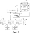
- Fig. 3 shows how operator, designer, and vendor of an automation system can benefit from the optimized maintenance tool and method according to the present invention.
- a maintenance tool 330 as described in Fig. 2 .
- a server 120 is integrated into the control unit 110 and is coupled with the maintenance tool 330.
- a network couples all components 130-170 with the engineering system 100 and/or the server 120.
- each component may comprise a memory unit 130a, 140a, 150a, 160a, and 170a for storing the respective maintenance data developed during operation of the system.
- component 140 may comprise an additional memory unit 140b which contains the information of memory units 160a and 170a of sub-components 160 and 170.
- the server 120 may forward the acquired data to the maintenance tool 330 which processes these data as described above. Furthermore, the server 120 may forward the same or specifically selected data to the component manufacturer/vendor and the system designer. To this end specific filters can be implemented to provide the respective parties with only suitable data.
- the engineering system can provide the information about the components for example, via Internet, directly to the maintenance tool 330, the component manufacturer/vendor 310, and the system designer 320. Also, certain environmental characteristics of the specific location or specific measurable parameters of a component can be directly measured.
- Component 150 in Fig. 3 is equipped with two sensors 340 and 350 which are coupled with the network to provide the respective data. These sensors may measure, temperature, pressure, stress, etc.
- Fig. 4 shows the generally different influences of the optimized maintenance tool and method on different stages of the development of an automation system.
- a simplified flow chart as shown in Fig. 4 shows, for example, a first step 410 in which the product or process is designed. In the following step 420, the specific mechanical and electrical designs are made. Engineering takes place in the following step 430. After installation and commissioning in step 440, the system is operated and maintained in step 450. This leads to the step 460 of collecting experience as described above in the specific embodiments. The dotted arrows show which steps in this process, in particular for future developments can be influenced by such a method. The acquired experience leads to information and data that might improve the different design phases in step 410 - 430 as well as in the improvement of an existing system, for example, as shown with step 470 indicating modernization and upgrade of an existing system.
Landscapes
- Business, Economics & Management (AREA)
- Engineering & Computer Science (AREA)
- Human Resources & Organizations (AREA)
- Physics & Mathematics (AREA)
- General Physics & Mathematics (AREA)
- Strategic Management (AREA)
- Economics (AREA)
- Entrepreneurship & Innovation (AREA)
- Quality & Reliability (AREA)
- Operations Research (AREA)
- Marketing (AREA)
- Tourism & Hospitality (AREA)
- General Business, Economics & Management (AREA)
- Theoretical Computer Science (AREA)
- Development Economics (AREA)
- Educational Administration (AREA)
- Game Theory and Decision Science (AREA)
- Automation & Control Theory (AREA)
- Management, Administration, Business Operations System, And Electronic Commerce (AREA)
- General Factory Administration (AREA)
Description
- The present application relates to automation systems and in particular to the optimized maintenance of such a system.
- In modern factories or plants, engineering systems are provided to define processing steps in manufacturing and/or controlling certain process steps within the system: To this end, these engineering systems usually comprise a plurality of mechanical and/or electrical components, such as process technology field devices, control devices, drives, sensors, microprocessors, personal computers, software, etc. Each component often consists of hardware and software/firmware, additional aids for configuration, parameterization, and diagnosis, as well as information for operating and maintaining the component. Such information is provided by the specific vendor of the component or if the component is designed in house, by the specific engineering team.
- System manufacturers combine these components provided by specific vendors if necessary with their own components to design and build complex automation systems. The operator of such a designed system relies on the specific information provided by the system manufacturer and vendors to perform the required steps for maintaining the system operable. The most critical factor in operating automation systems is down time due to failure of a component. Therefore, maintaining the system operable is one of the most important tasks of a system operator. Specific maintenance teams monitor the system and repair specific components in case of a system failure. However, to keep down time at a minimum, preventive maintenance is required. Thus, failure can be avoided by exchanging specific parts according to a maintenance plan or scheme. Such a scheme or plan is simply defined according to the information provided by the system designer or vendor of a component which informs, for example, how often a specific part should be replaced.
EP1544771 discloses a diagnosis engine that refers to a risk assessment database and antirisk measure database, and calculates along the time sequence a risk estimate amount in case of failure for each device and a maintenance cost in executing a measure method in advance, and then adds the risk estimate amount and maintenance cost along the time sequence to calculate an optimum maintenance period of the device.US2004/07468 discloses a fleet management system that manages a plurality of machines, having a fleet manager that includes a communication conduit coupled to the machines for receiving status information related to the machines and a repository coupled to the communication conduit for receiving and storing the status information.US6141629 discloses that the maintenance due times of components of a machine are determined according to the status of user-performed in-house maintenance and according to the occurrence of abnormalities during machine operation. - Nevertheless, many factors influence the operability of specific parts of a complex system. Thus, a maintenance scheme/plan as described above is far from being optimized and does not take specific influencing factors into account. For example, prescribed maintenance intervals might be too long or too short due to the specific design of the system or specific usage of devices. Hence, either avoidable system failure or unnecessary maintenance may occur, thus, increasing operating costs of the respective system.
- A method for maintaining a system consisting of a plurality of components, according to an exemplary embodiment of the invention comprises the steps of collecting maintenance information for each component of the system for which maintenance information is available; providing a maintenance schedule for components of the system; operating the system; and maintaining the system wherein during scheduled maintenance of a component information about the status of that component is acquired, during a failure of a component information about the failure of that component is acquired, and modifying the maintenance schedule according to the acquired information, wherein the method further comprises a step of determining information about an interrelationship of components; comprising the respective inherent properties of each component as well as their particular placement within the system, specific environmental influences created either by the location or by adjoining components and specific mechanical and/or electrical influences of certain components on other components.
- The method may further comprise the step of determining maintenance information for components of the system for which no maintenance information is available. The information acquired during a scheduled maintenance may indicate that a service interval is too long, correct,or too short. The step of modifying may include the step of adjusting the service interval. The method further may comprise the step of determining information about environmental conditions of a location of at least one component. The method may further comprise the step of providing feedback information for a system designer. The method may further comprise the step of providing feedback information for a component manufacturer. The feedback information can be automatically generated via an electronic messaging system.
- A system for optimizing system maintenance according to another exemplary embodiment comprises a plurality of components; a data network coupling the plurality of components; and a maintenance unit for collecting and processing information generated during normal processing as well as during maintenance of components of the system according to a predefined maintenance schedule, wherein the predefined maintenance schedule is modified by the maintenance tool according to the processed information, wherein the information comprises information about an interrelationship of components, comprising the respective inherent properties of each component as well as their particular placement within the system, specific environmental influences created either by the location or by adjoining components and specific mechanical and/or electrical influences of certain components on other components.
- The information may include maintenance information and/or normal processing information. Each component may comprise a memory unit for storing the maintenance information. The memory unit may store information for the component itself and for subordinated components. The system may further comprise means for generating electronic messages including the collected maintenance information and for providing a vendor and/or system designer with the electronic message. The system may further comprise sensors for sensing environmental conditions of a component. At least one component can be provided by an external vendor or component manufacturer. The information acquired during a scheduled maintenance may indicate any kind of deviation from a predefined status.
-
-
Fig. 1 shows an exemplary automation system according to the prior art; -
Fig. 2 shows a first exemplary flow chart of a system design and operation according to the present invention; -
Fig. 3 shows an exemplary embodiment of an automation system according to the present invention; -
Fig. 4 shows a second exemplary flow chart of a system design and operation according to the present invention. -
Fig. 1 shows a conventional automation system consisting of anengineering system 100 coupled with acontrol unit 110 and a plurality of components 130-170, for example as shown component A, B, C. In this exemplary system, component B further comprises sub-components B1 and B2. Each component 130 - 170 might be provided by a different vendor and might comprise specific performance characteristics. Each vendor might recommend a certain maintenance plan and depending on the type of component a certain replacement schedule for specific parts, for example, wear and tear elements. The respective maintenance personnel will, thus, follow these instructions regardless of the overall characteristics of the entire system. Thus, certain maintenance services could be performed too late or too early. In addition, no feedback will generally be provided to the vendor or system designer. The maintenance personnel might at most adjust the maintenance schedule for the specific part. Nevertheless, any influence of the specific part and its specific needs on the entire system will be completely neglected. - Thus, according to the present invention, a new approach for an improved method and tool for optimized maintenance is proposed. For example,
Fig. 2 shows a flow chart of specific steps in the design and operation of a system consisting of a plurality of independent and/or dependent components. In afirst step 200, the manufacturer of, for example, an automation system, designs the system using a plurality of, e.g., standard components, customized standard components, and/or specifically designed components. Instep 210, these components and their specific properties are defined using, if necessary, external information, for example, provided by the respective vendor as indicated witharrows 280. According to this information, once the overall system is designed, a specific maintenance schedule/plan is defined in the followingsteps step 220 using, for example, external information about specific properties, wear and tear of each component, and recommended maintenance intervals and other maintenance data as indicated byarrows 270. If no information is available, then the operator/user may define a custom maintenance schedule/plan if the respective component requires maintenance. Instep 230, these data are stored in a custom maintenance data base and used to design a custom maintenance scheme/plan taking into consideration the respective inherent properties of each component as well as their particular placement within the system. Thus, for example, specific environmental influences created either by the location or by adjoining components can be taken into account. Furthermore, specific mechanical and/or electrical influences of certain components on other components can also be considered. Thus, any influence by any component as well as specific influences of a component location on its performance can be taken into account. - However, many other factors might not been known at the time of the design. Thus, as shown in
step 240, during operation of the system, certain maintenance services and/or repair services will be performed. Each service, whether maintenance or repair, will provide the respective personnel with additional data about the respective task which has been performed. For example, a scheduled maintenance service might require a replacement of a wear and tear part. For example, a valve might require replacement after 10,000 cycles. However, the exchange of this part might show, that the respective part does not show the anticipated wear and replacement was too early. Also, a unscheduled repair service will provide information of, for example, a higher wear and tear of a specific part than anticipated, for example, the valve might show significant damage after only 8,000 cycles. Also other components might show measurable wear and tear. For example, a electrically operated brake needs maintenance after 5,000 activations according to the vendor. However, the service might show only 50% wear and tear. Additional influencing factors might be discovered due to specific types of failures, such as, over heating, additional mechanical stress factors, etc. In particular, due to the specific maintenance/repair service, the respective personnel might be able to deduct certain cross-influential factors which have not been considered during the design phase. This information can now be used by a maintenance tool instep 250 to modify the data base and the maintenance chedule/plan. Thus, an adaptive process takes place during which an optimized customary maintenance schedule/plan can be developed. Furthermore, the respective data base can also be used to generate information about certain cross-influential factors created by the combination of two or more components that are linked in specific ways. Thus, whenever certain combinations of components are used in a new design, these specific cross-influential factors can be taking into account. - A maintenance service might provide predefined information that can be forwarded automatically or manual to the maintenance tool. For example, the following choices might be available for the service personnel:
- Maintenance service was performed to late (component failure occurred)
- Maintenance service was absolutely necessary
- Maintenance service was necessary
- Maintenance service could have been performed later (optional : include time interval)
- Maintenance service was unnecessary
- The maintenance service might further provide information about an improved maintenance service plan, recommendations to the vendor, and any actual data about the specific component/part. This information can be directly forwarded to the maintenance tool and in addition, this information can be directly stored in the respective component if the component provides for such a storage feature.
- The combination of certain components and their respective effect on the overall system and on specific components can also be generated. For example, using component A in a specific combination with component B might result in 10 % increase of wear and tear of part X, whereas a combination of component B and C might decrease a mechanical stress on a specific part Y in component B. Furthermore, environmental factors such as temperature, humidity, pressure, etc. might have positive or negative influence on the performance of certain parts which might not be known or provided by a vendor. Also, a combination of components and environmental conditions might cause certain effects on the overall or specific performance of certain components or parts. All these information can be collected in
step 250 during the operation of the system and be used to improve the performance of the system and keep the down time of the system at a minimum. -
Fig. 2 also shows an additionaloptional step 260 of providing feedback. In this step, the above described specific information can be forwarded to the respective vendors and/or to the designers of the system. This should not be an automatic action without influence of the maintenance personnel to avoid that proprietary information is sent to a vendor. Some of this feedback information can be generated automatically and, for example, be provided to the vendor via email, SMS, in form of a letter, or any other suitable communication form. Thus, the method and tool for optimizing the maintenance service allows not only for improving the respective automation system but also to provide vendors with specific data which can be either used to inform other customers about specific properties of the component or their parts or to improve the respective parts of the components or to improve the recommended maintenance plans for a component. Furthermore, the basic knowledge about specific components can be improved and adapted to allow a better design of new systems. The feedback may comprise, for example, identification and maintenance data of the specific component which can be vendor- or system-specific, maintenance plan recommended by the vendor, application information, and experience of the user/maintenance personnel. -
Fig. 3 shows how operator, designer, and vendor of an automation system can benefit from the optimized maintenance tool and method according to the present invention. InFig. 3 , the same system as shown inFig. 1 is improved by amaintenance tool 330 as described inFig. 2 . To this end, for example, aserver 120 is integrated into thecontrol unit 110 and is coupled with themaintenance tool 330. A network couples all components 130-170 with theengineering system 100 and/or theserver 120. Furthermore, each component may comprise amemory unit component 140 may comprise anadditional memory unit 140b which contains the information ofmemory units sub-components server 120 may forward the acquired data to themaintenance tool 330 which processes these data as described above. Furthermore, theserver 120 may forward the same or specifically selected data to the component manufacturer/vendor and the system designer. To this end specific filters can be implemented to provide the respective parties with only suitable data. Furthermore, or alternatively the engineering system can provide the information about the components for example, via Internet, directly to themaintenance tool 330, the component manufacturer/vendor 310, and thesystem designer 320. Also, certain environmental characteristics of the specific location or specific measurable parameters of a component can be directly measured.Component 150 inFig. 3 , for example, is equipped with twosensors -
Fig. 4 shows the generally different influences of the optimized maintenance tool and method on different stages of the development of an automation system. A simplified flow chart as shown inFig. 4 shows, for example, afirst step 410 in which the product or process is designed. In thefollowing step 420, the specific mechanical and electrical designs are made. Engineering takes place in the followingstep 430. After installation and commissioning instep 440, the system is operated and maintained instep 450. This leads to thestep 460 of collecting experience as described above in the specific embodiments. The dotted arrows show which steps in this process, in particular for future developments can be influenced by such a method. The acquired experience leads to information and data that might improve the different design phases in step 410 - 430 as well as in the improvement of an existing system, for example, as shown withstep 470 indicating modernization and upgrade of an existing system.
Claims (16)
- A method for maintaining a system (100) consisting of a plurality of components (130 - 170), comprising the steps of:- collecting maintenance information for each component (130 - 170) of the system (100) for which maintenance information is available;- providing a maintenance schedule for components (130 - 170) of the system (100);- operating said system (100); and- maintaining said system (100) wherein:- during scheduled maintenance of a component (130- 170) information about the status of that component (130 - 170) is acquired;- during a failure of a component (130 - 170) information about the failure of that component (130 - 170) is acquired; and- modifying the maintenance schedule according to the acquired information, characterized in that the method further comprises a step of determining information about interrelationship of components (130 - 170) comprising the respective inherent properties of each component as well as their particular placement within the system, specific environmental influences created either by the location or by adjoining components and specific mechanical and/or electrical influences of certain components on other components.
- The method according to claim 1, further comprising the step of determining maintenance information for components (130 - 170) of the system (100) for which no maintenance information is available.
- The method according to claim 1, wherein the information acquired during a scheduled maintenance indicates that a service interval is too long, correct, or too short.
- The method according to claim 3, wherein the step of modifying includes the step of adjusting said service interval.
- The method according to claim 1, further comprising the step of determining information about environmental conditions of a location of at least one component (130 - 170) .
- The method according to claim 1, further comprising the step of providing feedback information for a system designer.
- The method according to claim 1, further comprising the step of providing feedback information for a vendor or component manufacturer.
- The method according to claim 6, wherein the feedback information is automatically generated via an electronic messaging system.
- The method according to claim 1, wherein at least one component is provided by an external vendor or component manufacturer.
- The method according to claim 1, wherein the information acquired during a scheduled maintenance indicates any kind of deviation from a predefined status.
- An apparatus for system maintenance comprising:- a plurality of components (130 - 170);- a data network coupling the plurality of components (130 - 170);- a maintenance unit (110) adapted to collect and process information generated during normal processing as well as during maintenance of the plurality of components (130 - 170) of the system according to a predefined maintenance schedule, wherein the predefined maintenance schedule is modified by the maintenance unit (110) according to the processed information, and wherein the information comprises information about an interrelationship of the plurality of components (130 - 170) comprising the respective inherent properties of each component as well as their particular placement within the system, specific environmental influences created either by the location or by adjoining components and specific mechanical and/or electrical influences of certain components on other components.
- The apparatus according to claim 11, wherein the information includes maintenance information and/or normal processing information.
- The apparatus according to claim 11, wherein each component (130 - 170) comprises a memory unit (130a - 170a) for storing said maintenance information.
- The apparatus according to claim 13, wherein the memory unit (130a - 170a) stores information for the component (130 - 170) itself and for subordinated components (140b).
- The apparatus according to claim 11, further comprising means for generating electronic messages including said collected maintenance information and for providing a vendor and/or system designer with said electronic message.
- The apparatus according to claim 11, further comprising sensors (340, 350) for sensing environmental conditions of a component (130 - 170).
Applications Claiming Priority (1)
| Application Number | Priority Date | Filing Date | Title |
|---|---|---|---|
| PCT/US2005/023087 WO2007005002A1 (en) | 2005-06-30 | 2005-06-30 | Method and tool for optimized system maintenance |
Publications (3)
| Publication Number | Publication Date |
|---|---|
| EP1896949A1 EP1896949A1 (en) | 2008-03-12 |
| EP1896949A4 EP1896949A4 (en) | 2012-05-16 |
| EP1896949B1 true EP1896949B1 (en) | 2021-04-07 |
Family
ID=37604756
Family Applications (1)
| Application Number | Title | Priority Date | Filing Date |
|---|---|---|---|
| EP05770197.1A Expired - Lifetime EP1896949B1 (en) | 2005-06-30 | 2005-06-30 | Method and tool for optimized system maintenance |
Country Status (4)
| Country | Link |
|---|---|
| US (1) | US20090076874A1 (en) |
| EP (1) | EP1896949B1 (en) |
| CN (1) | CN101185065A (en) |
| WO (1) | WO2007005002A1 (en) |
Families Citing this family (15)
| Publication number | Priority date | Publication date | Assignee | Title |
|---|---|---|---|---|
| US20140207514A1 (en) * | 2013-01-22 | 2014-07-24 | General Electric Company | Inspection data provision |
| US20090106072A1 (en) * | 2007-10-19 | 2009-04-23 | Oracle International Corporation | Associating Assets with Agreements |
| WO2009081229A1 (en) * | 2007-12-21 | 2009-07-02 | Renault Trucks | Process for updating the scheduling of a service stop for a machine |
| FR2934397B1 (en) * | 2008-07-28 | 2025-02-28 | Eurocopter France | IMPROVED PROCESS FOR ORGANIZING AIRCRAFT MAINTENANCE |
| GB201103157D0 (en) * | 2011-02-24 | 2011-04-06 | Bae Systems Plc | Reliability centered maintenance |
| US9158303B2 (en) | 2012-03-27 | 2015-10-13 | General Electric Company | Systems and methods for improved reliability operations |
| SE1250298A1 (en) * | 2012-03-27 | 2013-09-28 | Scania Cv Ab | Vehicle inspection device and procedure |
| FI128899B (en) | 2012-09-19 | 2021-02-26 | Konecranes Oyj | Predictive maintenance procedures and systems |
| US9122253B2 (en) | 2012-11-06 | 2015-09-01 | General Electric Company | Systems and methods for dynamic risk derivation |
| US9280617B2 (en) | 2012-11-06 | 2016-03-08 | General Electric Company | Systems and methods for improved reliability operations |
| JP6104643B2 (en) | 2013-03-04 | 2017-03-29 | 三菱重工業株式会社 | Operation plan creation device, operation plan creation method, and operation plan creation program |
| JP6341729B2 (en) * | 2014-04-04 | 2018-06-13 | 三菱日立パワーシステムズ株式会社 | Operation plan creation evaluation device and operation plan creation evaluation method |
| CN103985021A (en) * | 2014-06-11 | 2014-08-13 | 张劲松 | Hotel equipment management system and implementation method thereof |
| US10718284B2 (en) | 2018-10-05 | 2020-07-21 | Emissions-Based Maintenance LLC | Engine emission status-based maintenance |
| CN111832776B (en) * | 2020-06-28 | 2024-02-06 | 海南太美航空股份有限公司 | Cluster maintenance management method and system |
Citations (2)
| Publication number | Priority date | Publication date | Assignee | Title |
|---|---|---|---|---|
| US6141629A (en) * | 1997-07-16 | 2000-10-31 | Komatsu Ltd. | Method and apparatus for determining machine maintenance due times |
| US20040073468A1 (en) * | 2002-10-10 | 2004-04-15 | Caterpillar Inc. | System and method of managing a fleet of machines |
Family Cites Families (12)
| Publication number | Priority date | Publication date | Assignee | Title |
|---|---|---|---|---|
| US5627764A (en) * | 1991-10-04 | 1997-05-06 | Banyan Systems, Inc. | Automatic electronic messaging system with feedback and work flow administration |
| US5970437A (en) * | 1996-10-03 | 1999-10-19 | Gorman; Alexander J. | Computerized management of plant maintenance and program therefor |
| US6006171A (en) * | 1997-07-28 | 1999-12-21 | Vines; Caroline J. | Dynamic maintenance management system |
| US6606546B2 (en) * | 1999-12-01 | 2003-08-12 | Sinex Holdings, Llc | Aircraft maintenance program manager |
| MXPA03001692A (en) * | 2000-08-23 | 2004-06-22 | Gen Electric | Method for training service personnel to service selected equipment. |
| US6980959B1 (en) * | 2000-10-17 | 2005-12-27 | Accenture Llp | Configuring mechanical equipment |
| US6677854B2 (en) * | 2001-10-05 | 2004-01-13 | Case, Llc | Remote vehicle diagnostic system |
| JP2003177815A (en) * | 2001-12-07 | 2003-06-27 | Komatsu Ltd | Industrial Machine Maintenance System |
| US7380213B2 (en) * | 2001-12-28 | 2008-05-27 | Kimberly-Clark Worldwide, Inc. | User interface for reporting event-based production information in product manufacturing |
| JP2003303014A (en) * | 2002-04-09 | 2003-10-24 | Toshiba Corp | Plant equipment maintenance management method and apparatus |
| WO2005038613A2 (en) * | 2003-10-17 | 2005-04-28 | Hydralift Amclyde, Inc. | Equipment component monitoring and replacement management system |
| JP4237610B2 (en) * | 2003-12-19 | 2009-03-11 | 株式会社東芝 | Maintenance support method and program |
-
2005
- 2005-06-30 WO PCT/US2005/023087 patent/WO2007005002A1/en not_active Ceased
- 2005-06-30 EP EP05770197.1A patent/EP1896949B1/en not_active Expired - Lifetime
- 2005-06-30 US US11/917,399 patent/US20090076874A1/en not_active Abandoned
- 2005-06-30 CN CNA2005800498904A patent/CN101185065A/en active Pending
Patent Citations (2)
| Publication number | Priority date | Publication date | Assignee | Title |
|---|---|---|---|---|
| US6141629A (en) * | 1997-07-16 | 2000-10-31 | Komatsu Ltd. | Method and apparatus for determining machine maintenance due times |
| US20040073468A1 (en) * | 2002-10-10 | 2004-04-15 | Caterpillar Inc. | System and method of managing a fleet of machines |
Also Published As
| Publication number | Publication date |
|---|---|
| WO2007005002A1 (en) | 2007-01-11 |
| EP1896949A4 (en) | 2012-05-16 |
| US20090076874A1 (en) | 2009-03-19 |
| CN101185065A (en) | 2008-05-21 |
| EP1896949A1 (en) | 2008-03-12 |
Similar Documents
| Publication | Publication Date | Title |
|---|---|---|
| US20090076874A1 (en) | Method and Tool for Optimized System Maintenance | |
| EP2150865B1 (en) | Automatic maintenance estimation in a plant environment | |
| US9183518B2 (en) | Methods and systems for scheduling a predicted fault service call | |
| CN101542518B (en) | Remote monitoring and diagnosis system | |
| US8626610B2 (en) | Equipment management system, equipment management method and program | |
| US20160349737A1 (en) | Manufacturing efficiency optimization platform and tool condition monitoring and prediction method | |
| US9665090B2 (en) | Systems and methods for rule-based control system reliability | |
| EP2189899A1 (en) | Systems and methods to provide customized release notes during a software system upgrade of a process control system | |
| US9081656B2 (en) | Methods and systems for predicting a fault | |
| WO2004072749A1 (en) | Service facility for providing remote diagnostic and maintenance services to a process plant | |
| JP4982196B2 (en) | Replacement part order processing apparatus, replacement part order processing method, and replacement part order processing program | |
| EP1909235A2 (en) | Systems and methods for remote diagnostics of devices | |
| US20220382245A1 (en) | Artificial intelligence alarm management | |
| WO2014018190A1 (en) | Systems and methods for control reliability operations | |
| KR101996070B1 (en) | Method and apparatus for efficiently managing part | |
| US20090112672A1 (en) | Method and Arrangement for Optimized Maintenance of Components | |
| US20080307406A1 (en) | Device and method for checking the current software installation in field devices in a distributed system, in particular an automation system | |
| WO2010021789A1 (en) | Managing machine tool and auxiliary equipment preventative maintenance | |
| CN117950380B (en) | MES-driven station terminal production process control system and method | |
| JP2012164307A (en) | Information processing method for plant diagnostic system and plant diagnostic system | |
| JP2002197212A (en) | POS terminal remote maintenance system | |
| JP2017027449A (en) | Platform and method for optimizing manufacturing efficiency by monitoring and predicting tool state | |
| EP3945385A1 (en) | Continuous flow engine monitoring method and system | |
| US20150212809A1 (en) | Method for the Usage-Controlled Updating of a Software Product | |
| WO2018061142A1 (en) | Inkjet recording device system and display screen of external control device used therefor |
Legal Events
| Date | Code | Title | Description |
|---|---|---|---|
| PUAI | Public reference made under article 153(3) epc to a published international application that has entered the european phase |
Free format text: ORIGINAL CODE: 0009012 |
|
| 17P | Request for examination filed |
Effective date: 20071024 |
|
| AK | Designated contracting states |
Kind code of ref document: A1 Designated state(s): DE FR GB IT |
|
| RBV | Designated contracting states (corrected) |
Designated state(s): DE FR GB IT |
|
| DAX | Request for extension of the european patent (deleted) | ||
| RAP1 | Party data changed (applicant data changed or rights of an application transferred) |
Owner name: SIEMENS ENERGY, INC. Owner name: SIEMENS AKTIENGESELLSCHAFT |
|
| RAP1 | Party data changed (applicant data changed or rights of an application transferred) |
Owner name: SIEMENS AKTIENGESELLSCHAFT |
|
| A4 | Supplementary search report drawn up and despatched |
Effective date: 20120416 |
|
| RIC1 | Information provided on ipc code assigned before grant |
Ipc: G21C 17/00 20060101ALI20120410BHEP Ipc: G06F 11/30 20060101AFI20120410BHEP |
|
| RAP1 | Party data changed (applicant data changed or rights of an application transferred) |
Owner name: SIEMENS AKTIENGESELLSCHAFT |
|
| 17Q | First examination report despatched |
Effective date: 20131017 |
|
| RAP1 | Party data changed (applicant data changed or rights of an application transferred) |
Owner name: SIEMENS AKTIENGESELLSCHAFT |
|
| STAA | Information on the status of an ep patent application or granted ep patent |
Free format text: STATUS: EXAMINATION IS IN PROGRESS |
|
| RAP1 | Party data changed (applicant data changed or rights of an application transferred) |
Owner name: SIEMENS AKTIENGESELLSCHAFT |
|
| GRAP | Despatch of communication of intention to grant a patent |
Free format text: ORIGINAL CODE: EPIDOSNIGR1 |
|
| STAA | Information on the status of an ep patent application or granted ep patent |
Free format text: STATUS: GRANT OF PATENT IS INTENDED |
|
| RIC1 | Information provided on ipc code assigned before grant |
Ipc: G06Q 10/06 20120101ALI20201027BHEP Ipc: G07C 5/00 20060101ALI20201027BHEP Ipc: G06Q 10/00 20120101ALI20201027BHEP Ipc: G21C 17/00 20060101ALI20201027BHEP Ipc: G06F 11/30 20060101AFI20201027BHEP Ipc: G05B 23/02 20060101ALI20201027BHEP |
|
| INTG | Intention to grant announced |
Effective date: 20201127 |
|
| GRAS | Grant fee paid |
Free format text: ORIGINAL CODE: EPIDOSNIGR3 |
|
| GRAA | (expected) grant |
Free format text: ORIGINAL CODE: 0009210 |
|
| STAA | Information on the status of an ep patent application or granted ep patent |
Free format text: STATUS: THE PATENT HAS BEEN GRANTED |
|
| AK | Designated contracting states |
Kind code of ref document: B1 Designated state(s): DE FR GB IT |
|
| REG | Reference to a national code |
Ref country code: GB Ref legal event code: FG4D |
|
| REG | Reference to a national code |
Ref country code: DE Ref legal event code: R096 Ref document number: 602005057182 Country of ref document: DE |
|
| REG | Reference to a national code |
Ref country code: DE Ref legal event code: R097 Ref document number: 602005057182 Country of ref document: DE |
|
| PLBE | No opposition filed within time limit |
Free format text: ORIGINAL CODE: 0009261 |
|
| STAA | Information on the status of an ep patent application or granted ep patent |
Free format text: STATUS: NO OPPOSITION FILED WITHIN TIME LIMIT |
|
| 26N | No opposition filed |
Effective date: 20220110 |
|
| GBPC | Gb: european patent ceased through non-payment of renewal fee |
Effective date: 20210707 |
|
| PG25 | Lapsed in a contracting state [announced via postgrant information from national office to epo] |
Ref country code: GB Free format text: LAPSE BECAUSE OF NON-PAYMENT OF DUE FEES Effective date: 20210707 |
|
| PGFP | Annual fee paid to national office [announced via postgrant information from national office to epo] |
Ref country code: FR Payment date: 20230905 Year of fee payment: 20 |
|
| PGFP | Annual fee paid to national office [announced via postgrant information from national office to epo] |
Ref country code: IT Payment date: 20230926 Year of fee payment: 20 |
|
| PGFP | Annual fee paid to national office [announced via postgrant information from national office to epo] |
Ref country code: DE Payment date: 20230913 Year of fee payment: 20 |
|
| REG | Reference to a national code |
Ref country code: DE Ref legal event code: R071 Ref document number: 602005057182 Country of ref document: DE |