EP1896160B1 - Method and apparatus for energy reduction in acid gas capture processes - Google Patents
Method and apparatus for energy reduction in acid gas capture processes Download PDFInfo
- Publication number
- EP1896160B1 EP1896160B1 EP06757887A EP06757887A EP1896160B1 EP 1896160 B1 EP1896160 B1 EP 1896160B1 EP 06757887 A EP06757887 A EP 06757887A EP 06757887 A EP06757887 A EP 06757887A EP 1896160 B1 EP1896160 B1 EP 1896160B1
- Authority
- EP
- European Patent Office
- Prior art keywords
- absorbent
- acid
- organic acid
- desorber
- rich
- Prior art date
- Legal status (The legal status is an assumption and is not a legal conclusion. Google has not performed a legal analysis and makes no representation as to the accuracy of the status listed.)
- Not-in-force
Links
Images





Classifications
-
- B—PERFORMING OPERATIONS; TRANSPORTING
- B01—PHYSICAL OR CHEMICAL PROCESSES OR APPARATUS IN GENERAL
- B01D—SEPARATION
- B01D53/00—Separation of gases or vapours; Recovering vapours of volatile solvents from gases; Chemical or biological purification of waste gases, e.g. engine exhaust gases, smoke, fumes, flue gases, aerosols
- B01D53/14—Separation of gases or vapours; Recovering vapours of volatile solvents from gases; Chemical or biological purification of waste gases, e.g. engine exhaust gases, smoke, fumes, flue gases, aerosols by absorption
-
- B—PERFORMING OPERATIONS; TRANSPORTING
- B01—PHYSICAL OR CHEMICAL PROCESSES OR APPARATUS IN GENERAL
- B01D—SEPARATION
- B01D53/00—Separation of gases or vapours; Recovering vapours of volatile solvents from gases; Chemical or biological purification of waste gases, e.g. engine exhaust gases, smoke, fumes, flue gases, aerosols
- B01D53/14—Separation of gases or vapours; Recovering vapours of volatile solvents from gases; Chemical or biological purification of waste gases, e.g. engine exhaust gases, smoke, fumes, flue gases, aerosols by absorption
- B01D53/1425—Regeneration of liquid absorbents
-
- Y—GENERAL TAGGING OF NEW TECHNOLOGICAL DEVELOPMENTS; GENERAL TAGGING OF CROSS-SECTIONAL TECHNOLOGIES SPANNING OVER SEVERAL SECTIONS OF THE IPC; TECHNICAL SUBJECTS COVERED BY FORMER USPC CROSS-REFERENCE ART COLLECTIONS [XRACs] AND DIGESTS
- Y02—TECHNOLOGIES OR APPLICATIONS FOR MITIGATION OR ADAPTATION AGAINST CLIMATE CHANGE
- Y02C—CAPTURE, STORAGE, SEQUESTRATION OR DISPOSAL OF GREENHOUSE GASES [GHG]
- Y02C20/00—Capture or disposal of greenhouse gases
- Y02C20/40—Capture or disposal of greenhouse gases of CO2
Definitions
- the present invention addresses this particular problem as it introduces a new method and apparatus for reducing the energy requirements for absorbent regeneration by adding a component that simplifies the regeneration, but has limited effect on the operation of the absorber.
- the conventional layout for an absorption plant for acid gas (e.g. CO 2 or H 2 S) removal from e.g. exhaust gases is given on in figure 1 in simplified form.
- the gas to be treated 1 enters the absorber bottom and passes upwards through the absorber A1.
- the lean absorbent 3 enters the absorber A1 at a position above the column internals and passes downwards counter-current to the gas. Intimate contact between the phases and the properties of the absorbent make the acid gas leave the gas phase and become absorbed in the absorbent, usually in part caused by an exothermic chemical reaction in the liquid phase.
- the absorber can be equipped with a water-wash section at the top, but this is irrelevant to the invention.
- the cleaned gas 2 leaves the absorber A1 at the top, and the liquid, which is now rich in acid gas 4, leaves the absorber A1 at the bottom.
- the rich absorbent solution 4 is then passed through a heat exchanger H1 where it is heated to a temperature close to that of the desorber, and then passed as stream 5 to the desorber D1.
- the equilibria governing the solution of the acid gas, including the chemical reactions, are reversed by an increase in the temperature.
- the increased temperature is achieved by introducing direct or indirect heating to the desorber reboiler R1, as shown in figure 1 .
- the absorbent leaves the desorber as stream 7 and as lean absorbent 6 from the reboiler R1 which also generates steam 11 for the desorber.
- Lean absorbent 6 passes through the heat exchanger H1 simultaneously heating the rich absorbent, before it may be cooled and lead back to the absorber A1 as stream 3.
- CO 2 from the desorber, together with water vapour 8 passes to a condenser C1 where the temperature is reduced and water condensed and returned to the desorber 9.
- the gas phase containing mainly CO 2 10 is the product.
- conventional technology like the Fluor Econamine process will typically use about 3850 MJ of energy per ton CO 2 removed for absorption of CO 2 from exhaust from a coal fired power station ( S. Reddy et al. Proceedings 2nd national conference on Carbon Sequestration, pp 1-11, Alexandria USA, Ma 2003 ). Improvements to these processes have been made and the Fluor Econamine Plus process is claimed to have a regeneration energy requirement of about 3250 MJ/ton CO 2 removed, ( S. Reddy et al. Proceedings 2nd national conference on Carbon Sequestration, pp 1-11, Alexandria USA, Ma 2003 ).
- acid salt solutions e.g. sodium adipate
- the acid salt removed from the circuit by precipitation (ref : O. Erga, Ind. Eng. Chem. Fundam., 25(1986),pp 692-695 ) in a process for removal of SO 2 from flue gases.
- the lean solution is heated and solvent evaporated.
- supersaturation of an adipic acid salt can be achieved and precipitation results in a lower concentration of the absorbent. This enhances the absorption.
- GB 484 714 A describes a process for removing SO 2 from exhaust gases using a bisulphite-sulphite solution. This is now commercialized as the so called Wellman-Lord process with sodium as cation.
- US 20040253159 A1 describes a process for recovering CO 2 from a feed gas stream with a regenerated absorbent comprising at least tertiary amine absorbent and an oxidation inhibitor.
- the present invention provides a method for removing and recovering acid gases, CO 2 and/or H 2 S from a gaseous mixture in an absorption plant where the gaseous mixture passes through a basic absorbent in an absorber, and where the rich absorbent (i.e. absorbent with acid gas) passes through a heat exchanger, and then through a desorber where the acid gas is stripped off from the rich absorbent characterized in that organic acid(s) dissolved in an organic solvent is (are) added to the rich absorbent stream in or before the desorber, in order to enhance the release of acid gas by shifting the acid gas equilibria toward the gas side, and where the organic acid(s) is (are) subsequently separated from the lean absorbent (i.e.
- the organic acid may be a naphtenic acid, a C 1 -C 18 carboxylic acid, an amino acid or a mixture thereof.
- the organic acid is such that a mixture thereof with lean absorbent (i.e. absorbent after stripping off the acid gas) will form two separate phases after release of the acid gas, one rich in organic acid and another rich in absorbent and water, and the two phases are separated in a liquid phase separator. The separation is achieved by using an organic solvent for partial dissolution of the organic acid. The lean absorbent added to the absorber will thereby be low in organic acid.
- Another aspect of the present invention is that the added organic acid(s) can bond to and remove heavy metals from the solution.
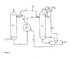
- the present invention provides an apparatus for performing the method, which includes supply of organic acid 5b, 13,14a ( fig.2 ) placed before the desorber D1 or before the cross flow heat exchanger H1, a separator S1 placed in the recycle line 3b-3a between the heat exchanger H1 and the absorber A1 to separate the organic acid 15 from the lean absorbent 3b.
- a desorber overhead separator S2 can be included in order to separate the three phases formed, and pipelines installed for recycling of the organic rich phase and a phase rich in water and absorbent.
- the separator can be of any type used for liquid/liquid separation, e.g. a gravity settler or a centrifugal separator.
- the present application provides apparatus with recycle pipelines14a, 14b and 14c for the organic acid and a separator S3 for organic solvent placed after the cross flow heat exchanger with a return pipe16 for solvent to the lean absorbent stream 6.
- Figure 1 shows a conventional absorption plant for CO 2 removal.
- figure 2 it is shown an example of a typical flowsheet for a CO 2 removal plant where organic acid not dissolved in a solvent is used.
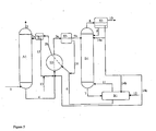
- Figure 3 shows an alternative to the configuration in figure 2 where the organic acid containing solution is returned to the rich and lean absorbent solution before the cross flow heat exchanger.
- Figure 4 shows the effect of partial neutralization on the partial pressure of CO 2 over an MEA solution at 120°C.
- Figure 5 is an example of a flowsheet for a CO 2 removal plant operating according to the invention, where the organic acid is added together with an organic solvent and where the organic solvent is separated from the rich absorbent flow before entering the desorber and returned to the lean absorbent stream before the cross flow heat exchanger.
- Figure 6 shows the case of heavy metal removal, e.g. mercury, from the gas stream to be treated by extraction into the organic acid containing liquid phase and the subsequent removal of the metal in a separate wash of a bleed from the absorption process.
- heavy metal removal e.g. mercury
- FIG 7 CO 2 equilibrium data for MEA contacted with an organic acid in a solvent at two temperatures 40 and 80°C illustrating the desired effects are shown.
- the invention is related to how to change the equilibrium curves for desorption, in the desorber, without affecting to any large extent the equilibrium curves in the absorber.
- the basis for the invention is to add a partially or fully dissolvable constituent, preferably an organic acid, e.g. a naphtenic acid, a carboxylic acid or an amino acid to the rich absorbent stream at positions exemplified in figures 2 and 3 by stream 13 as being just before the rich absorbent desorber inlet or the rich absorbent cross flow heat exchanger H1 inlet. These positions are just examples and non-limitative.
- the acid(s) is (are) added as a mixture of an organic solvent and the organic acid(s).
- the acid(s) shall have the property of being increasingly dissolvable in the aqueous absorbent solution with increasing temperature. Thus, a high solubility of the acid is found in the desorber.
- the second part of the invention therefore relates to the method for removing acid from the lean absorbent solution.
- This is achieved by selecting the properties of the organic acid added such that when the lean absorbent solution is cooled, as in the cross flow heat exchanger H1, the mixture forms two phases.
- One phase will be rich in absorbent and water and contain some remaining organic acid whereas the other phase will be rich in organic acid and contain some absorbent and water.
- Figures 2 and 3 show a process where the organic acid is not dissolved in a solvent.
- an acid rich phase 15 is separated in a conventional separator S1 and removed from the absorbent rich phase 3b.
- S1 is placed on the lean absorbent stream 3b - 3a and can be a separator or a combined cooler and separator.
- the absorbent rich phase 3a then passes to the absorber A1.
- the organic acid rich phase 15 can be returned at a variety of locations, preferably into the hot rich absorbent stream 5a before it enters the desorber D1, as shown in figure 2 , or to the rich absorbent stream 4 before it enters the cross flow heat exchanger H1, as shown in figure 3 .
- the latter may have the added advantage that more heat can be transferred in the cross flow heat exchanger.
- Part of the organic acid will, depending on its volatility, evaporate in the desorber and flow with CO 2 , water, and absorbent 8 to the desorber overhead condenser S2 and be cooled and condense there.
- the condenser S2 three phases will be formed.
- the gas phase 10 will contain mainly CO 2 and is the product.
- the liquid will form two phases where one will be rich in organic acid 14 and the other rich in water and absorbent 9.
- the organic acid rich phase will be returned, as a nonlimiting example, to the desorber top 14a or to the reboiler 14b, as shown in figure 2 , or as stream 14c to the rich absorbent stream 4 as shown in figure 3 . A mix of both can also be used.
- organic basic components e.g. all amines and mixtures thereof, for example the alkanol amines, e.g. MEA(monoethanolamine), DEA(diethanol amine), MDEA(methyl-diethanolamine), the di- and polyamines, e.g. AEEA (Aminoethyl-ethanolamine), DETA(diethylene-triamine), cyclic amines e.g..PZ(piperazine), and sterically hindered amines, e.g. AMP (Aminomethylpropanol), used as absorbents, but equally well with inorganic absorbents such as carbonates. It will also work in mixed systems based both on physical and chemical absorbents.
- organic basic components e.g. all amines and mixtures thereof, for example the alkanol amines, e.g. MEA(monoethanolamine), DEA(diethanol amine), MDEA(methyl-diethanolamine), the di- and polyamines,
- carboxylic acids in the range of C 1 - C 18 such as pentanoic acid, hexanoic acid, heptanoic acid, octanoic acid, nonanoic acid, decanoic acid, undecanoic acid, dodecanoic acid, tridecanoic acid, valeric acid and ethyl-hexanoic acid can be given.
- the naphtenic acids in the same range Also mixtures of carboxylic acids can be used, e.g. the commercially available blend Versatic 911. Examples of amino acids are: glycine, taurine, sarcosine, and proline.
- the carboxylic acid is used in mixture with an organic solvent, as shown in figure 5 .
- a separator S3 on the rich absorbent stream 5a - 5b must be added to separate off the organic solvent with its content of carboxylic acid. Thereby the existence of two liquid phases in the desorber is avoided.
- the organic solvent with some organic acid 16 will be returned to the lean absorbent flow 6 before the cross flow heat exchanger H 1.
- solvents are: Shellsol 80, Exxol 80 and Solvesso.
- Another aspect of the current invention is that carboxylic acids and naphtenic acids have the capability of bonding and removing heavy metals from the solution and thereby from the gas.
- Heavy metals, and in particular mercury (Hg) is a very dangerous pollutant from coal fired power stations.
- the invented method has the added potential to remove this mercury.
- This aspect is shown in figure 6 .
- bleed streams 17 and/or 18 of the phases rich in organic acid are taken out and washed with an inorganic acid/water solution 19.
- the mercury, and other heavy metals being extracted by the organic acid will be transferred to the aqueous solution and handled separately 20.
- the cleaned bleed streams 21 and 22 are returned to the lean absorbent stream, either to stream 6 or 3a or 3b.
- FIG 7 one example of experimental data on the effect on the CO 2 equilibria of equilibrating an MEA/water mixture with a solvent/organic acid mixture at 40°C and 80°C respectively, is shown.
- the shift in the equilibrium curve is most pronounced for the highest temperature which is the desired effect.
Landscapes
- Chemical & Material Sciences (AREA)
- Engineering & Computer Science (AREA)
- Analytical Chemistry (AREA)
- General Chemical & Material Sciences (AREA)
- Oil, Petroleum & Natural Gas (AREA)
- Chemical Kinetics & Catalysis (AREA)
- Gas Separation By Absorption (AREA)
- Treating Waste Gases (AREA)
- Physical Or Chemical Processes And Apparatus (AREA)
- Carbon And Carbon Compounds (AREA)
- Organic Low-Molecular-Weight Compounds And Preparation Thereof (AREA)
Abstract
Description
- Large emissions of greenhouse gases, and in particular CO2, are today recognized as one of the major causes of global warming. Absorption is the most frequently used technology for CO2 removal, but large scale removal from gases with low CO2 partial pressures is limited by economic considerations. The absorption of CO2 and H2S from natural gas, process gases and in particular exhaust gases from as for example fossil fuel based power stations, iron and steel plants, is associated with high requirements of energy for the regeneration of the absorbent.
- The present invention addresses this particular problem as it introduces a new method and apparatus for reducing the energy requirements for absorbent regeneration by adding a component that simplifies the regeneration, but has limited effect on the operation of the absorber.
- The conventional layout for an absorption plant for acid gas (e.g. CO2 or H2S) removal from e.g. exhaust gases is given on in
figure 1 in simplified form. The gas to be treated 1 enters the absorber bottom and passes upwards through the absorber A1. The lean absorbent 3 enters the absorber A1 at a position above the column internals and passes downwards counter-current to the gas. Intimate contact between the phases and the properties of the absorbent make the acid gas leave the gas phase and become absorbed in the absorbent, usually in part caused by an exothermic chemical reaction in the liquid phase. To limit losses of absorbent, the absorber can be equipped with a water-wash section at the top, but this is irrelevant to the invention. - The cleaned
gas 2 leaves the absorber A1 at the top, and the liquid, which is now rich inacid gas 4, leaves the absorber A1 at the bottom. The richabsorbent solution 4 is then passed through a heat exchanger H1 where it is heated to a temperature close to that of the desorber, and then passed asstream 5 to the desorber D1. - In the desorber the equilibria governing the solution of the acid gas, including the chemical reactions, are reversed by an increase in the temperature. The increased temperature is achieved by introducing direct or indirect heating to the desorber reboiler R1, as shown in
figure 1 . After reversal of the equilibrium and desorption of the acid gases, the absorbent leaves the desorber asstream 7 and as lean absorbent 6 from the reboiler R1 which also generatessteam 11 for the desorber. Lean absorbent 6 passes through the heat exchanger H1 simultaneously heating the rich absorbent, before it may be cooled and lead back to the absorber A1 asstream 3. CO2 from the desorber, together withwater vapour 8 passes to a condenser C1 where the temperature is reduced and water condensed and returned to thedesorber 9. The gas phase containing mainlyCO 2 10 is the product. - The main obstacle to taking this technology into worldwide use for e.g. bulk CO2-removal, is the energy required for absorbent regeneration in the desorber. For example, conventional technology, like the Fluor Econamine process will typically use about 3850 MJ of energy per ton CO2 removed for absorption of CO2 from exhaust from a coal fired power station (S. Reddy et al. Proceedings 2nd national conference on Carbon Sequestration, pp 1-11, Alexandria USA, Ma 2003). Improvements to these processes have been made and the Fluor Econamine Plus process is claimed to have a regeneration energy requirement of about 3250 MJ/ton CO2 removed, (S. Reddy et al. Proceedings 2nd national conference on Carbon Sequestration, pp 1-11, Alexandria USA, Ma 2003). Also Mitsubishi has developed new processes and their new absorbent KS1 is claimed to require about 3250 MJ/ton CO2 removed, (S. Reddy et al. Proceedings 2nd national conference on Carbon Sequestration, pp 1-11, Alexandria USA, Ma 2003 and Mimura et.al. Energy Convers. Mgmt. 36(1995), pp397-400 and Chem. Eng. Comm., 170(1998), pp 245-260).
- However, these reductions in energy requirement are not enough to make absorption accepted as a viable technology for e.g. CO2 removal from exhaust gases. No exact number for the necessary reduction in regeneration energy requirement can be given, but it is believed that the range 1500-1800 MJ/ton CO2 removed could be acceptable.
- It is known that organic acids can be formed as degradation products when amines are used as absorbents in the process. This is the case also for most systems with added degradation inhibitors since these are not totally immune to oxidation. When traces of oxygen are present, amines such as MEA will react with this to form e.g. glycine, glycolic acid and oxalic acid. (These compounds can further interact with themselves to form other degradation products.) (ref :Leci and Goldthorpe.;Energy Convers. Mgmt,33,5-8,477-485,1992). These and other acids build up in the solution and circulate both through the absorber and desorber. These acids shift the equilibrium curves for both acid gas absorption and for desorption, but the total effect may be positive as a small reduction in energy requirements can be obtained. This way of operation has the disadvantage that the acids, which shift the equilibrium curves, are present in the whole process. They can thus not be present in large concentrations, and absorbent reclaiming will be necessary on a regular basis for removing these acids and other degradation products as heat stable salts.
- It is known that acid salt solutions, e.g. sodium adipate, can be used in high concentration in the desorber section and the acid salt removed from the circuit by precipitation (ref : O. Erga, Ind. Eng. Chem. Fundam., 25(1986),pp 692-695) in a process for removal of SO2 from flue gases. In this process, the lean solution is heated and solvent evaporated. In this way, supersaturation of an adipic acid salt can be achieved and precipitation results in a lower concentration of the absorbent. This enhances the absorption.
-
GB 484 714 A -
US 20040253159 A1 describes a process for recovering CO2 from a feed gas stream with a regenerated absorbent comprising at least tertiary amine absorbent and an oxidation inhibitor. - The present invention provides a method for removing and recovering acid gases, CO2 and/or H2S from a gaseous mixture in an absorption plant where the gaseous mixture passes through a basic absorbent in an absorber, and where the rich absorbent (i.e. absorbent with acid gas) passes through a heat exchanger, and then through a desorber where the acid gas is stripped off from the rich absorbent characterized in that organic acid(s) dissolved in an organic solvent is (are) added to the rich absorbent stream in or before the desorber, in order to enhance the release of acid gas by shifting the acid gas equilibria toward the gas side, and where the organic acid(s) is (are) subsequently separated from the lean absorbent (i.e. absorbent after stripping off the acid gas) as a separate liquid phase, by extraction into an organic solvent before the lean absorbent is returned to the absorber. With this method, the energy consumption of the process is substantially reduced. The organic acid may be a naphtenic acid, a C1-C18 carboxylic acid, an amino acid or a mixture thereof. The organic acid is such that a mixture thereof with lean absorbent (i.e. absorbent after stripping off the acid gas) will form two separate phases after release of the acid gas, one rich in organic acid and another rich in absorbent and water, and the two phases are separated in a liquid phase separator. The separation is achieved by using an organic solvent for partial dissolution of the organic acid. The lean absorbent added to the absorber will thereby be low in organic acid.
- Another aspect of the present invention is that the added organic acid(s) can bond to and remove heavy metals from the solution.
- Further, the present invention provides an apparatus for performing the method, which includes supply of
organic acid fig.2 ) placed before the desorber D1 or before the cross flow heat exchanger H1, a separator S1 placed in therecycle line 3b-3a between the heat exchanger H1 and the absorber A1 to separate theorganic acid 15 from the lean absorbent 3b. A desorber overhead separator S2 can be included in order to separate the three phases formed, and pipelines installed for recycling of the organic rich phase and a phase rich in water and absorbent. The separator can be of any type used for liquid/liquid separation, e.g. a gravity settler or a centrifugal separator. - Further, the present application provides apparatus with recycle pipelines14a, 14b and 14c for the organic acid and a separator S3 for organic solvent placed after the cross flow heat exchanger with a return pipe16 for solvent to the lean
absorbent stream 6. -
Figure 1 shows a conventional absorption plant for CO2 removal. Infigure 2 it is shown an example of a typical flowsheet for a CO2 removal plant where organic acid not dissolved in a solvent is used.Figure 3 shows an alternative to the configuration infigure 2 where the organic acid containing solution is returned to the rich and lean absorbent solution before the cross flow heat exchanger.Figure 4 shows the effect of partial neutralization on the partial pressure of CO2 over an MEA solution at 120°C.Figure 5 is an example of a flowsheet for a CO2 removal plant operating according to the invention, where the organic acid is added together with an organic solvent and where the organic solvent is separated from the rich absorbent flow before entering the desorber and returned to the lean absorbent stream before the cross flow heat exchanger.Figure 6 shows the case of heavy metal removal, e.g. mercury, from the gas stream to be treated by extraction into the organic acid containing liquid phase and the subsequent removal of the metal in a separate wash of a bleed from the absorption process. Infigure 7 CO2 equilibrium data for MEA contacted with an organic acid in a solvent at two temperatures 40 and 80°C illustrating the desired effects are shown. - The invention is related to how to change the equilibrium curves for desorption, in the desorber, without affecting to any large extent the equilibrium curves in the absorber.
- The basis for the invention is to add a partially or fully dissolvable constituent, preferably an organic acid, e.g. a naphtenic acid, a carboxylic acid or an amino acid to the rich absorbent stream at positions exemplified in
figures 2 and3 bystream 13 as being just before the rich absorbent desorber inlet or the rich absorbent cross flow heat exchanger H1 inlet. These positions are just examples and non-limitative. The acid(s) is (are) added as a mixture of an organic solvent and the organic acid(s). The acid(s) shall have the property of being increasingly dissolvable in the aqueous absorbent solution with increasing temperature. Thus, a high solubility of the acid is found in the desorber. - Adding acid to the absorbents, being a base, will neutralize the absorbent and shift the acid gas equilibrium toward the gas side. This will increase the partial pressure of the acid gas in the desorber D1 compared to the original process. The change of partial pressure will depend on the amount of organic acid dissolved in the aqueous absorbent and on the amount added. An example of the effect of partial neutralization on the equilibrium curves is given in
figure 4 . An increase in the partial pressure of CO2 will ease the desorption and make it less energy demanding. An example is given in table 1 which is a result of a simulation. Here CO2 absorption into the absorbent MEA (Mono-ethanolamine) is taken as an example. The absorbent is neutralized to different extents by an organic acid and this will shift acid gas loadings significantly. It can be seen that a 25% degree of neutralisation reduces the amount of energy required for CO2 absorption from the normal figure of 3890 MJ/ton CO2 to less than 2000 MJ/ton CO2. A further increase in the degree of neutralization reduces the energy requirement further and at 32% neutralization, the energy requirement is well below 1500 MJ/ton CO2.Table 1 Fraction of absorbent neutralized Energy requirement (MJ/tCO2) Absorbent lean loading mole CO2/mole abs. Absorbent rich loading mole CO2/mole abs. 0.0 3890 0.2000 0.457 0.05 3440 0.2100 0.457 0.07 3200 0.2160 0.457 0.09 2990 0.2310 0.457 0.17 2480 0.2400 0.457 0.25 1950 0.2666 0.457 0.32 1440 0.2960 0.457 - The second part of the invention therefore relates to the method for removing acid from the lean absorbent solution. This is achieved by selecting the properties of the organic acid added such that when the lean absorbent solution is cooled, as in the cross flow heat exchanger H1, the mixture forms two phases. One phase will be rich in absorbent and water and contain some remaining organic acid whereas the other phase will be rich in organic acid and contain some absorbent and water.
Figures 2 and3 show a process where the organic acid is not dissolved in a solvent. As shown infigure 2 , an acidrich phase 15 is separated in a conventional separator S1 and removed from the absorbentrich phase 3b. S1 is placed on the leanabsorbent stream 3b - 3a and can be a separator or a combined cooler and separator. The absorbentrich phase 3a then passes to the absorber A1. The organic acidrich phase 15 can be returned at a variety of locations, preferably into the hot richabsorbent stream 5a before it enters the desorber D1, as shown infigure 2 , or to the richabsorbent stream 4 before it enters the cross flow heat exchanger H1, as shown infigure 3 . The latter may have the added advantage that more heat can be transferred in the cross flow heat exchanger. - Part of the organic acid will, depending on its volatility, evaporate in the desorber and flow with CO2, water, and absorbent 8 to the desorber overhead condenser S2 and be cooled and condense there. In the condenser S2 three phases will be formed. The
gas phase 10 will contain mainly CO2 and is the product. The liquid will form two phases where one will be rich in organic acid 14 and the other rich in water andabsorbent 9. The organic acid rich phase will be returned, as a nonlimiting example, to the desorber top 14a or to thereboiler 14b, as shown infigure 2 , or asstream 14c to the richabsorbent stream 4 as shown infigure 3 . A mix of both can also be used. - The process will work with organic basic components, e.g. all amines and mixtures thereof, for example the alkanol amines, e.g. MEA(monoethanolamine), DEA(diethanol amine), MDEA(methyl-diethanolamine), the di- and polyamines, e.g. AEEA (Aminoethyl-ethanolamine), DETA(diethylene-triamine), cyclic amines e.g..PZ(piperazine), and sterically hindered amines, e.g. AMP (Aminomethylpropanol), used as absorbents, but equally well with inorganic absorbents such as carbonates. It will also work in mixed systems based both on physical and chemical absorbents.
- As non exclusive examples of organic acids, carboxylic acids in the range of C1 - C18 such as pentanoic acid, hexanoic acid, heptanoic acid, octanoic acid, nonanoic acid, decanoic acid, undecanoic acid, dodecanoic acid, tridecanoic acid, valeric acid and ethyl-hexanoic acid can be given. Also included are the naphtenic acids in the same range. Also mixtures of carboxylic acids can be used, e.g. the commercially available blend Versatic 911. Examples of amino acids are: glycine, taurine, sarcosine, and proline.
- According to the invention the carboxylic acid is used in mixture with an organic solvent, as shown in
figure 5 . In the case the mixture is not totally soluble in the absorbent solution at desorber D1 temperature, a separator S3 on the richabsorbent stream 5a - 5b must be added to separate off the organic solvent with its content of carboxylic acid. Thereby the existence of two liquid phases in the desorber is avoided. The organic solvent with someorganic acid 16 will be returned to the leanabsorbent flow 6 before the cross flowheat exchanger H 1. Non-exclusive examples of solvents are: Shellsol 80, Exxol 80 and Solvesso. - Another aspect of the current invention is that carboxylic acids and naphtenic acids have the capability of bonding and removing heavy metals from the solution and thereby from the gas. Heavy metals, and in particular mercury (Hg) is a very dangerous pollutant from coal fired power stations. The invented method has the added potential to remove this mercury. This aspect is shown in
figure 6 . Here bleedstreams 17 and/or 18 of the phases rich in organic acid are taken out and washed with an inorganic acid/water solution 19. The mercury, and other heavy metals being extracted by the organic acid, will be transferred to the aqueous solution and handled separately 20. The cleaned bleed streams 21 and 22 are returned to the lean absorbent stream, either tostream - In
figure 7 , one example of experimental data on the effect on the CO2 equilibria of equilibrating an MEA/water mixture with a solvent/organic acid mixture at 40°C and 80°C respectively, is shown. The shift in the equilibrium curve is most pronounced for the highest temperature which is the desired effect.
Claims (11)
- Method for removing and recovering acid gases, CO2 and/or H2S, from a gaseous mixture in an absorption plant, where the gaseous mixture passes through a basic absorbent in an absorber, and where the rich absorbent (i.e. absorbent with the acid gas) passes through a heat exchanger, and then through a desorber where the acid gas is stripped off from the rich absorbent,
characterized in
that organic acid(s) dissolved in an organic solvent is (are) added to the rich absorbent stream before the desorber in order to enhance the acid gas release by shifting the acid gas equilibria towards the gas side, and where the organic acid(s) is (are) subsequently separated from the lean absorbent (i.e. absorbent after stripping off the acid gas) as a separate liquid phase, by extraction into an organic solvent before the lean absorbent is returned to the absorber. - Method according to claim 1, wherein the organic acid is a naphtenic acid or a C1-C18 carboxylic acid or a mixture thereof.
- Method according to any of claims 1-2 wherein the organic acid is such that a mixture thereof with lean absorbent will form two separate phases after release of the acid gas, one rich in organic acid and another rich in absorbent and water, and the two phases are separated.
- Method according to any of claims 1-3, wherein the organic solvent used for partial dissolution of the organic acid is separated from the rich absorbent stream by extraction before the desorber and returned to the lean absorbent stream.
- Method according to any of claims 1-4, wherein part of the organic acid evaporated in the desorber is separated in a condenser where three phases will be formed.
- Method according to any of claims 1-5 wherein the organic acid is used to bond and remove heavy metals from the solution.
- Apparatus for performing the method of any of claims 1-5 comprising an absorber (A1), a heat exchanger (H1), a desorber (D1) and a reboiler (R1), characterized by- at least one supply of organic acid (5b, 13, 14a) placed before the desorber or before the cross flow heat exchanger,- a separator/condenser (S1) placed in a recycle line between the heat exchanger and the absorber to separate the organic acid (15) from the lean absorbent (3b).
- Apparatus according to claim 7, wherein a desorber overhead separator (S2) is included in order to separate the three phases formed, and pipelines for recycling of the organic acid rich phase (14a, 14b, 14c) and a phase rich in water and absorbent are installed (9).
- Apparatus according to claim 7 or 8, wherein the organic acid (13) is supplied and mixed with the organic acid (15) from the separator (S1) just before the rich absorbent cross flow heat exchanger (H1) inlet.
- Apparatus according to any of claims 7 -9, wherein a separator (S3) is placed between the heat exchanger (H1) and the desorber (D1) inlet to separate a second liquid phase comprising organic solvent with some organic acid to be returned to the lean absorbent before the heat exchanger.
- Apparatus according to any of claims 7 -10, wherein an acid wash device (AW1) for removal of heavy metal from the organic phase is placed such that metal containing organic acid can be removed, washed and returned.
Priority Applications (1)
| Application Number | Priority Date | Filing Date | Title |
|---|---|---|---|
| PL06757887T PL1896160T3 (en) | 2005-06-28 | 2006-06-28 | Method and apparatus for energy reduction in acid gas capture processes |
Applications Claiming Priority (2)
| Application Number | Priority Date | Filing Date | Title |
|---|---|---|---|
| NO20053148A NO326645B1 (en) | 2005-06-28 | 2005-06-28 | Process and apparatus for removing and recovering acid gases, CO2 and / or H2S. |
| PCT/NO2006/000249 WO2007001190A1 (en) | 2005-06-28 | 2006-06-28 | Method and apparatus for energy reduction in acid gas capture processes |
Publications (3)
| Publication Number | Publication Date |
|---|---|
| EP1896160A1 EP1896160A1 (en) | 2008-03-12 |
| EP1896160A4 EP1896160A4 (en) | 2009-11-11 |
| EP1896160B1 true EP1896160B1 (en) | 2011-12-28 |
Family
ID=35295301
Family Applications (1)
| Application Number | Title | Priority Date | Filing Date |
|---|---|---|---|
| EP06757887A Not-in-force EP1896160B1 (en) | 2005-06-28 | 2006-06-28 | Method and apparatus for energy reduction in acid gas capture processes |
Country Status (15)
| Country | Link |
|---|---|
| US (1) | US7993433B2 (en) |
| EP (1) | EP1896160B1 (en) |
| KR (1) | KR20080052547A (en) |
| CN (1) | CN101213010B (en) |
| AT (1) | ATE538865T1 (en) |
| AU (1) | AU2006262995B2 (en) |
| BR (1) | BRPI0613800A2 (en) |
| CA (1) | CA2613251C (en) |
| DK (1) | DK1896160T3 (en) |
| EA (1) | EA012146B1 (en) |
| ES (1) | ES2380976T3 (en) |
| NO (1) | NO326645B1 (en) |
| PL (1) | PL1896160T3 (en) |
| PT (1) | PT1896160E (en) |
| WO (1) | WO2007001190A1 (en) |
Families Citing this family (21)
| Publication number | Priority date | Publication date | Assignee | Title |
|---|---|---|---|---|
| DE102006036228A1 (en) * | 2006-08-03 | 2008-02-07 | Universität Dortmund | Process for separating CO2 from gas mixtures |
| AU2008255555B2 (en) * | 2007-05-29 | 2012-05-03 | University Of Regina | Method and absorbent composition for recovering a gaseous component from a gas stream |
| DE102008007087A1 (en) * | 2008-01-31 | 2009-08-06 | Universität Dortmund | Separating carbon dioxide from gas mixture or gas flow, particularly flue gas stream of power stations or synthesis gases, involves bringing in contact gas mixture or gas flow with carbon dioxide absorbing agent |
| DE102010013729A1 (en) * | 2010-03-31 | 2011-10-06 | Siemens Aktiengesellschaft | Method and apparatus for separating carbon dioxide from an exhaust gas of a fossil-fired power plant |
| JP5686987B2 (en) * | 2010-04-20 | 2015-03-18 | 三菱日立パワーシステムズ株式会社 | Exhaust gas treatment system equipped with carbon dioxide chemical absorption equipment |
| CN102101011B (en) * | 2010-12-24 | 2013-01-23 | 华电环保系统工程有限公司 | Wet desulphurization method for coal-fired power plant and additive used by same |
| JP2014505593A (en) | 2011-02-02 | 2014-03-06 | アルストム テクノロジー リミテッド | Renewable energy reduction method |
| US9901860B2 (en) | 2011-02-02 | 2018-02-27 | General Electric Technology Gmbh | Apparatus for removing an acid gas from a gas stream |
| EP2484427B1 (en) | 2011-02-08 | 2017-07-19 | Neste Oyj | A two-stage gas washing method |
| WO2012128715A1 (en) | 2011-03-22 | 2012-09-27 | Climeon Ab | Method for conversion of low temperature heat to electricity and cooling, and system therefore |
| EP2559476A1 (en) * | 2011-08-18 | 2013-02-20 | Siemens Aktiengesellschaft | Method and device for extracting volatile degradation products from the absorption circuit of a CO2 separation process |
| EP2564918B1 (en) | 2011-08-31 | 2018-03-07 | Neste Oyj | A two-stage gas washing method applying sulfide precipitation and alkaline absorption |
| KR101264603B1 (en) * | 2011-09-15 | 2013-05-24 | 강기준 | Apparatus and method for recovering of carboxylic acid and removing of water from reactor emission in the oxidation process of aromatic compound by using energy contributing combined distillation |
| GB201322606D0 (en) | 2013-12-19 | 2014-02-05 | Capture Ltd C | System for capture and release of acid gases |
| KR101583463B1 (en) * | 2014-03-06 | 2016-01-12 | 한국에너지기술연구원 | Energy Efficient Acidic gas Capture System and Methods |
| DE102015013796A1 (en) * | 2015-10-22 | 2017-04-27 | Linde Aktiengesellschaft | Process and apparatus for recovering gas products |
| US10589213B2 (en) | 2016-08-30 | 2020-03-17 | Fluor Technologies Corporation | Variable side cooling for acid gas removal |
| DE102022116362A1 (en) * | 2022-06-30 | 2024-01-04 | Fraunhofer-Gesellschaft zur Förderung der angewandten Forschung eingetragener Verein | Process for capturing carbon dioxide |
| CN117358050A (en) * | 2022-07-01 | 2024-01-09 | 中国石油天然气集团有限公司 | Carbon dioxide capture method and device |
| KR20240078149A (en) * | 2022-11-25 | 2024-06-03 | 현대자동차주식회사 | Gas capture system |
| JP2024115682A (en) * | 2023-02-15 | 2024-08-27 | 三菱重工業株式会社 | Co2 recovery device and control method |
Family Cites Families (6)
| Publication number | Priority date | Publication date | Assignee | Title |
|---|---|---|---|---|
| GB484714A (en) * | 1935-12-28 | 1938-05-10 | Univ Illinois | Improvements in processes of recovering sulphur dioxide from waste gases |
| US4133650A (en) * | 1976-05-28 | 1979-01-09 | Bayer Aktiengesellschaft | Removing sulfur dioxide from exhaust air |
| AR010696A1 (en) * | 1996-12-12 | 2000-06-28 | Sasol Tech Pty Ltd | A METHOD FOR THE ELIMINATION OF CARBON DIOXIDE FROM A PROCESS GAS |
| RU2191621C2 (en) * | 1998-04-06 | 2002-10-27 | Ниппон Ниюказаи Ко., Лтд. | Method of regenerating fluid absorbing acid gas containing methyl diethanolamine and derivative of piperazine of lower alkyls |
| US6395678B1 (en) * | 1999-09-01 | 2002-05-28 | Aero-Terra-Aqua Technologies Corporation | Bead and process for removing dissolved metal contaminants |
| US7056482B2 (en) | 2003-06-12 | 2006-06-06 | Cansolv Technologies Inc. | Method for recovery of CO2 from gas streams |
-
2005
- 2005-06-28 NO NO20053148A patent/NO326645B1/en not_active IP Right Cessation
-
2006
- 2006-06-28 CN CN2006800235138A patent/CN101213010B/en not_active Expired - Fee Related
- 2006-06-28 PL PL06757887T patent/PL1896160T3/en unknown
- 2006-06-28 KR KR1020087001281A patent/KR20080052547A/en not_active Abandoned
- 2006-06-28 WO PCT/NO2006/000249 patent/WO2007001190A1/en not_active Ceased
- 2006-06-28 DK DK06757887.2T patent/DK1896160T3/en active
- 2006-06-28 US US11/922,718 patent/US7993433B2/en not_active Expired - Fee Related
- 2006-06-28 EA EA200800153A patent/EA012146B1/en not_active IP Right Cessation
- 2006-06-28 ES ES06757887T patent/ES2380976T3/en active Active
- 2006-06-28 BR BRPI0613800-4A patent/BRPI0613800A2/en not_active IP Right Cessation
- 2006-06-28 AU AU2006262995A patent/AU2006262995B2/en not_active Ceased
- 2006-06-28 AT AT06757887T patent/ATE538865T1/en active
- 2006-06-28 CA CA2613251A patent/CA2613251C/en not_active Expired - Fee Related
- 2006-06-28 PT PT06757887T patent/PT1896160E/en unknown
- 2006-06-28 EP EP06757887A patent/EP1896160B1/en not_active Not-in-force
Also Published As
| Publication number | Publication date |
|---|---|
| CN101213010B (en) | 2011-11-09 |
| EP1896160A4 (en) | 2009-11-11 |
| EA012146B1 (en) | 2009-08-28 |
| WO2007001190A1 (en) | 2007-01-04 |
| EA200800153A1 (en) | 2008-06-30 |
| US7993433B2 (en) | 2011-08-09 |
| KR20080052547A (en) | 2008-06-11 |
| PT1896160E (en) | 2012-04-11 |
| NO20053148L (en) | 2006-12-29 |
| ATE538865T1 (en) | 2012-01-15 |
| AU2006262995B2 (en) | 2010-08-19 |
| CN101213010A (en) | 2008-07-02 |
| CA2613251A1 (en) | 2007-01-04 |
| AU2006262995A1 (en) | 2007-01-04 |
| DK1896160T3 (en) | 2012-04-23 |
| CA2613251C (en) | 2013-12-24 |
| NO20053148D0 (en) | 2005-06-28 |
| BRPI0613800A2 (en) | 2012-05-22 |
| PL1896160T3 (en) | 2013-03-29 |
| US20090293722A1 (en) | 2009-12-03 |
| ES2380976T3 (en) | 2012-05-22 |
| NO326645B1 (en) | 2009-01-26 |
| EP1896160A1 (en) | 2008-03-12 |
Similar Documents
| Publication | Publication Date | Title |
|---|---|---|
| US7993433B2 (en) | Method and apparatus for energy reduction in acid gas capture | |
| US6165433A (en) | Carbon dioxide recovery with composite amine blends | |
| US7459134B2 (en) | Method of decarbonating a combustion fume with extraction of the solvent contained in the purified fume | |
| EP1061045B1 (en) | Carbon dioxide recovery from an oxygen containing mixture | |
| US8357344B2 (en) | Gas deacidizing method using an absorbent solution with vaporization and/or purification of a fraction of the regenerated absorbent solution | |
| US6592829B2 (en) | Carbon dioxide recovery plant | |
| CA2311202C (en) | System for recovering carbon dioxide from a lean feed | |
| CN102227262B (en) | Method for regenerating ion exchange resin using sulfurous acid | |
| CN112426865A (en) | System for capturing and releasing acid gases | |
| KR20160058826A (en) | Optimization of stripper feed configuration for rich/lean solvent regeneration | |
| KR20120116431A (en) | Alcohol-based gas stripping process | |
| WO2011016906A2 (en) | Process for simultaneous removal of carbon dioxide and sulfur oxides from flue gas | |
| EP4420759A1 (en) | Process for regenerating a liquid absorbent | |
| WO2013081460A1 (en) | Method for depleting an exhaust gas stream in gaseous acid | |
| MX2008000288A (en) | Method and apparatus for energy reduction in acid gas capture processes | |
| HK40115825A (en) | Process for regenerating a liquid absorbent |
Legal Events
| Date | Code | Title | Description |
|---|---|---|---|
| PUAI | Public reference made under article 153(3) epc to a published international application that has entered the european phase |
Free format text: ORIGINAL CODE: 0009012 |
|
| 17P | Request for examination filed |
Effective date: 20080116 |
|
| AK | Designated contracting states |
Kind code of ref document: A1 Designated state(s): AT BE BG CH CY CZ DE DK EE ES FI FR GB GR HU IE IS IT LI LT LU LV MC NL PL PT RO SE SI SK TR |
|
| DAX | Request for extension of the european patent (deleted) | ||
| DAX | Request for extension of the european patent (deleted) | ||
| R17P | Request for examination filed (corrected) |
Effective date: 20080116 |
|
| A4 | Supplementary search report drawn up and despatched |
Effective date: 20090911 |
|
| 17Q | First examination report despatched |
Effective date: 20091230 |
|
| GRAP | Despatch of communication of intention to grant a patent |
Free format text: ORIGINAL CODE: EPIDOSNIGR1 |
|
| GRAS | Grant fee paid |
Free format text: ORIGINAL CODE: EPIDOSNIGR3 |
|
| GRAA | (expected) grant |
Free format text: ORIGINAL CODE: 0009210 |
|
| AK | Designated contracting states |
Kind code of ref document: B1 Designated state(s): AT BE BG CH CY CZ DE DK EE ES FI FR GB GR HU IE IS IT LI LT LU LV MC NL PL PT RO SE SI SK TR |
|
| REG | Reference to a national code |
Ref country code: GB Ref legal event code: FG4D |
|
| REG | Reference to a national code |
Ref country code: CH Ref legal event code: EP |
|
| REG | Reference to a national code |
Ref country code: AT Ref legal event code: REF Ref document number: 538865 Country of ref document: AT Kind code of ref document: T Effective date: 20120115 |
|
| REG | Reference to a national code |
Ref country code: IE Ref legal event code: FG4D |
|
| REG | Reference to a national code |
Ref country code: DE Ref legal event code: R096 Ref document number: 602006026716 Country of ref document: DE Effective date: 20120223 |
|
| REG | Reference to a national code |
Ref country code: PT Ref legal event code: SC4A Free format text: AVAILABILITY OF NATIONAL TRANSLATION Effective date: 20120328 Ref country code: NL Ref legal event code: T3 |
|
| REG | Reference to a national code |
Ref country code: SE Ref legal event code: TRGR |
|
| REG | Reference to a national code |
Ref country code: DK Ref legal event code: T3 |
|
| RAP2 | Party data changed (patent owner data changed or rights of a patent transferred) |
Owner name: NTNU NORWEGIAN UNIVERSITY OF SCIENCE AND TECHNOLOG |
|
| PG25 | Lapsed in a contracting state [announced via postgrant information from national office to epo] |
Ref country code: LT Free format text: LAPSE BECAUSE OF FAILURE TO SUBMIT A TRANSLATION OF THE DESCRIPTION OR TO PAY THE FEE WITHIN THE PRESCRIBED TIME-LIMIT Effective date: 20111228 |
|
| REG | Reference to a national code |
Ref country code: ES Ref legal event code: FG2A Ref document number: 2380976 Country of ref document: ES Kind code of ref document: T3 Effective date: 20120522 |
|
| LTIE | Lt: invalidation of european patent or patent extension |
Effective date: 20111228 |
|
| REG | Reference to a national code |
Ref country code: GR Ref legal event code: EP Ref document number: 20120400718 Country of ref document: GR Effective date: 20120417 |
|
| RAP2 | Party data changed (patent owner data changed or rights of a patent transferred) |
Owner name: NTNU NORWEGIAN UNIVERSITY OF SCIENCE AND TECHNOLOG |
|
| PG25 | Lapsed in a contracting state [announced via postgrant information from national office to epo] |
Ref country code: SI Free format text: LAPSE BECAUSE OF FAILURE TO SUBMIT A TRANSLATION OF THE DESCRIPTION OR TO PAY THE FEE WITHIN THE PRESCRIBED TIME-LIMIT Effective date: 20111228 Ref country code: LV Free format text: LAPSE BECAUSE OF FAILURE TO SUBMIT A TRANSLATION OF THE DESCRIPTION OR TO PAY THE FEE WITHIN THE PRESCRIBED TIME-LIMIT Effective date: 20111228 |
|
| PG25 | Lapsed in a contracting state [announced via postgrant information from national office to epo] |
Ref country code: CY Free format text: LAPSE BECAUSE OF FAILURE TO SUBMIT A TRANSLATION OF THE DESCRIPTION OR TO PAY THE FEE WITHIN THE PRESCRIBED TIME-LIMIT Effective date: 20111228 |
|
| PG25 | Lapsed in a contracting state [announced via postgrant information from national office to epo] |
Ref country code: BG Free format text: LAPSE BECAUSE OF FAILURE TO SUBMIT A TRANSLATION OF THE DESCRIPTION OR TO PAY THE FEE WITHIN THE PRESCRIBED TIME-LIMIT Effective date: 20120328 Ref country code: SK Free format text: LAPSE BECAUSE OF FAILURE TO SUBMIT A TRANSLATION OF THE DESCRIPTION OR TO PAY THE FEE WITHIN THE PRESCRIBED TIME-LIMIT Effective date: 20111228 Ref country code: EE Free format text: LAPSE BECAUSE OF FAILURE TO SUBMIT A TRANSLATION OF THE DESCRIPTION OR TO PAY THE FEE WITHIN THE PRESCRIBED TIME-LIMIT Effective date: 20111228 Ref country code: IS Free format text: LAPSE BECAUSE OF FAILURE TO SUBMIT A TRANSLATION OF THE DESCRIPTION OR TO PAY THE FEE WITHIN THE PRESCRIBED TIME-LIMIT Effective date: 20120428 |
|
| REG | Reference to a national code |
Ref country code: GB Ref legal event code: 732E Free format text: REGISTERED BETWEEN 20120726 AND 20120801 |
|
| PG25 | Lapsed in a contracting state [announced via postgrant information from national office to epo] |
Ref country code: RO Free format text: LAPSE BECAUSE OF FAILURE TO SUBMIT A TRANSLATION OF THE DESCRIPTION OR TO PAY THE FEE WITHIN THE PRESCRIBED TIME-LIMIT Effective date: 20111228 |
|
| REG | Reference to a national code |
Ref country code: AT Ref legal event code: MK05 Ref document number: 538865 Country of ref document: AT Kind code of ref document: T Effective date: 20111228 |
|
| PLBE | No opposition filed within time limit |
Free format text: ORIGINAL CODE: 0009261 |
|
| STAA | Information on the status of an ep patent application or granted ep patent |
Free format text: STATUS: NO OPPOSITION FILED WITHIN TIME LIMIT |
|
| 26N | No opposition filed |
Effective date: 20121001 |
|
| PGFP | Annual fee paid to national office [announced via postgrant information from national office to epo] |
Ref country code: ES Payment date: 20120613 Year of fee payment: 7 |
|
| REG | Reference to a national code |
Ref country code: DE Ref legal event code: R081 Ref document number: 602006026716 Country of ref document: DE Owner name: NTNU NORWEGIAN UNIVERSITY OF SCIENCE AND TECHN, NO Free format text: FORMER OWNER: NTNU TECHNOLOGY TRANSFER AS, TRONDHEIM, NO Effective date: 20121130 Ref country code: DE Ref legal event code: R097 Ref document number: 602006026716 Country of ref document: DE Effective date: 20121001 |
|
| PG25 | Lapsed in a contracting state [announced via postgrant information from national office to epo] |
Ref country code: MC Free format text: LAPSE BECAUSE OF NON-PAYMENT OF DUE FEES Effective date: 20120630 Ref country code: AT Free format text: LAPSE BECAUSE OF FAILURE TO SUBMIT A TRANSLATION OF THE DESCRIPTION OR TO PAY THE FEE WITHIN THE PRESCRIBED TIME-LIMIT Effective date: 20111228 |
|
| REG | Reference to a national code |
Ref country code: CH Ref legal event code: PL |
|
| REG | Reference to a national code |
Ref country code: CH Ref legal event code: PL |
|
| REG | Reference to a national code |
Ref country code: IE Ref legal event code: MM4A |
|
| REG | Reference to a national code |
Ref country code: PL Ref legal event code: T3 |
|
| PG25 | Lapsed in a contracting state [announced via postgrant information from national office to epo] |
Ref country code: IE Free format text: LAPSE BECAUSE OF NON-PAYMENT OF DUE FEES Effective date: 20120628 Ref country code: LI Free format text: LAPSE BECAUSE OF NON-PAYMENT OF DUE FEES Effective date: 20120630 Ref country code: CH Free format text: LAPSE BECAUSE OF NON-PAYMENT OF DUE FEES Effective date: 20120630 |
|
| PGFP | Annual fee paid to national office [announced via postgrant information from national office to epo] |
Ref country code: DK Payment date: 20130619 Year of fee payment: 8 Ref country code: GB Payment date: 20130619 Year of fee payment: 8 Ref country code: SE Payment date: 20130619 Year of fee payment: 8 Ref country code: CZ Payment date: 20130621 Year of fee payment: 8 Ref country code: DE Payment date: 20130620 Year of fee payment: 8 |
|
| PGFP | Annual fee paid to national office [announced via postgrant information from national office to epo] |
Ref country code: PL Payment date: 20130612 Year of fee payment: 8 Ref country code: FI Payment date: 20130613 Year of fee payment: 8 Ref country code: GR Payment date: 20130618 Year of fee payment: 8 Ref country code: PT Payment date: 20130618 Year of fee payment: 8 Ref country code: TR Payment date: 20130613 Year of fee payment: 8 Ref country code: IT Payment date: 20130624 Year of fee payment: 8 Ref country code: FR Payment date: 20130703 Year of fee payment: 8 Ref country code: NL Payment date: 20130619 Year of fee payment: 8 |
|
| PGFP | Annual fee paid to national office [announced via postgrant information from national office to epo] |
Ref country code: BE Payment date: 20130619 Year of fee payment: 8 |
|
| PG25 | Lapsed in a contracting state [announced via postgrant information from national office to epo] |
Ref country code: LU Free format text: LAPSE BECAUSE OF NON-PAYMENT OF DUE FEES Effective date: 20120628 |
|
| PG25 | Lapsed in a contracting state [announced via postgrant information from national office to epo] |
Ref country code: HU Free format text: LAPSE BECAUSE OF FAILURE TO SUBMIT A TRANSLATION OF THE DESCRIPTION OR TO PAY THE FEE WITHIN THE PRESCRIBED TIME-LIMIT Effective date: 20060628 |
|
| REG | Reference to a national code |
Ref country code: DE Ref legal event code: R119 Ref document number: 602006026716 Country of ref document: DE |
|
| REG | Reference to a national code |
Ref country code: PT Ref legal event code: MM4A Free format text: LAPSE DUE TO NON-PAYMENT OF FEES Effective date: 20141229 |
|
| REG | Reference to a national code |
Ref country code: DK Ref legal event code: EBP Effective date: 20140630 |
|
| REG | Reference to a national code |
Ref country code: NL Ref legal event code: V1 Effective date: 20150101 |
|
| PG25 | Lapsed in a contracting state [announced via postgrant information from national office to epo] |
Ref country code: CZ Free format text: LAPSE BECAUSE OF NON-PAYMENT OF DUE FEES Effective date: 20140628 Ref country code: PT Free format text: LAPSE BECAUSE OF NON-PAYMENT OF DUE FEES Effective date: 20141229 Ref country code: SE Free format text: LAPSE BECAUSE OF NON-PAYMENT OF DUE FEES Effective date: 20140629 Ref country code: FI Free format text: LAPSE BECAUSE OF NON-PAYMENT OF DUE FEES Effective date: 20140628 |
|
| REG | Reference to a national code |
Ref country code: SE Ref legal event code: EUG |
|
| GBPC | Gb: european patent ceased through non-payment of renewal fee |
Effective date: 20140628 |
|
| REG | Reference to a national code |
Ref country code: GR Ref legal event code: ML Ref document number: 20120400718 Country of ref document: GR Effective date: 20150105 |
|
| REG | Reference to a national code |
Ref country code: DE Ref legal event code: R119 Ref document number: 602006026716 Country of ref document: DE Effective date: 20150101 |
|
| REG | Reference to a national code |
Ref country code: FR Ref legal event code: ST Effective date: 20150227 |
|
| PG25 | Lapsed in a contracting state [announced via postgrant information from national office to epo] |
Ref country code: NL Free format text: LAPSE BECAUSE OF NON-PAYMENT OF DUE FEES Effective date: 20150101 |
|
| PG25 | Lapsed in a contracting state [announced via postgrant information from national office to epo] |
Ref country code: IT Free format text: LAPSE BECAUSE OF NON-PAYMENT OF DUE FEES Effective date: 20140628 Ref country code: DE Free format text: LAPSE BECAUSE OF NON-PAYMENT OF DUE FEES Effective date: 20150101 |
|
| PG25 | Lapsed in a contracting state [announced via postgrant information from national office to epo] |
Ref country code: FR Free format text: LAPSE BECAUSE OF NON-PAYMENT OF DUE FEES Effective date: 20140630 Ref country code: GB Free format text: LAPSE BECAUSE OF NON-PAYMENT OF DUE FEES Effective date: 20140628 Ref country code: GR Free format text: LAPSE BECAUSE OF NON-PAYMENT OF DUE FEES Effective date: 20150105 |
|
| PG25 | Lapsed in a contracting state [announced via postgrant information from national office to epo] |
Ref country code: DK Free format text: LAPSE BECAUSE OF NON-PAYMENT OF DUE FEES Effective date: 20140630 |
|
| REG | Reference to a national code |
Ref country code: ES Ref legal event code: FD2A Effective date: 20150804 |
|
| REG | Reference to a national code |
Ref country code: PL Ref legal event code: LAPE |
|
| PG25 | Lapsed in a contracting state [announced via postgrant information from national office to epo] |
Ref country code: ES Free format text: LAPSE BECAUSE OF NON-PAYMENT OF DUE FEES Effective date: 20140629 |
|
| PG25 | Lapsed in a contracting state [announced via postgrant information from national office to epo] |
Ref country code: PL Free format text: LAPSE BECAUSE OF NON-PAYMENT OF DUE FEES Effective date: 20140628 |
|
| PG25 | Lapsed in a contracting state [announced via postgrant information from national office to epo] |
Ref country code: BE Free format text: LAPSE BECAUSE OF NON-PAYMENT OF DUE FEES Effective date: 20140630 |
|
| PG25 | Lapsed in a contracting state [announced via postgrant information from national office to epo] |
Ref country code: TR Free format text: LAPSE BECAUSE OF NON-PAYMENT OF DUE FEES Effective date: 20140628 |