EP1895822A1 - A disposition for fastening and holding plane elements on a support - Google Patents
A disposition for fastening and holding plane elements on a support Download PDFInfo
- Publication number
- EP1895822A1 EP1895822A1 EP20070113811 EP07113811A EP1895822A1 EP 1895822 A1 EP1895822 A1 EP 1895822A1 EP 20070113811 EP20070113811 EP 20070113811 EP 07113811 A EP07113811 A EP 07113811A EP 1895822 A1 EP1895822 A1 EP 1895822A1
- Authority
- EP
- European Patent Office
- Prior art keywords
- plane element
- strip
- fastening
- abutment
- plane
- Prior art date
- Legal status (The legal status is an assumption and is not a legal conclusion. Google has not performed a legal analysis and makes no representation as to the accuracy of the status listed.)
- Withdrawn
Links
- 238000000034 method Methods 0.000 claims abstract description 8
- 239000004743 Polypropylene Substances 0.000 claims description 2
- 238000006073 displacement reaction Methods 0.000 claims description 2
- 239000004417 polycarbonate Substances 0.000 claims description 2
- 229920000515 polycarbonate Polymers 0.000 claims description 2
- -1 polypropylene Polymers 0.000 claims description 2
- 229920001155 polypropylene Polymers 0.000 claims description 2
- 239000002184 metal Substances 0.000 claims 1
- 239000000463 material Substances 0.000 description 3
- 239000004033 plastic Substances 0.000 description 2
- 229920003023 plastic Polymers 0.000 description 2
- 230000035939 shock Effects 0.000 description 2
- 230000000703 anti-shock Effects 0.000 description 1
- 230000006835 compression Effects 0.000 description 1
- 238000007906 compression Methods 0.000 description 1
- 238000004519 manufacturing process Methods 0.000 description 1
Images


Classifications
-
- F—MECHANICAL ENGINEERING; LIGHTING; HEATING; WEAPONS; BLASTING
- F17—STORING OR DISTRIBUTING GASES OR LIQUIDS
- F17C—VESSELS FOR CONTAINING OR STORING COMPRESSED, LIQUEFIED OR SOLIDIFIED GASES; FIXED-CAPACITY GAS-HOLDERS; FILLING VESSELS WITH, OR DISCHARGING FROM VESSELS, COMPRESSED, LIQUEFIED, OR SOLIDIFIED GASES
- F17C13/00—Details of vessels or of the filling or discharging of vessels
- F17C13/04—Arrangement or mounting of valves
-
- H—ELECTRICITY
- H05—ELECTRIC TECHNIQUES NOT OTHERWISE PROVIDED FOR
- H05K—PRINTED CIRCUITS; CASINGS OR CONSTRUCTIONAL DETAILS OF ELECTRIC APPARATUS; MANUFACTURE OF ASSEMBLAGES OF ELECTRICAL COMPONENTS
- H05K7/00—Constructional details common to different types of electric apparatus
- H05K7/14—Mounting supporting structure in casing or on frame or rack
- H05K7/1417—Mounting supporting structure in casing or on frame or rack having securing means for mounting boards, plates or wiring boards
- H05K7/1418—Card guides, e.g. grooves
-
- F—MECHANICAL ENGINEERING; LIGHTING; HEATING; WEAPONS; BLASTING
- F17—STORING OR DISTRIBUTING GASES OR LIQUIDS
- F17C—VESSELS FOR CONTAINING OR STORING COMPRESSED, LIQUEFIED OR SOLIDIFIED GASES; FIXED-CAPACITY GAS-HOLDERS; FILLING VESSELS WITH, OR DISCHARGING FROM VESSELS, COMPRESSED, LIQUEFIED, OR SOLIDIFIED GASES
- F17C2205/00—Vessel construction, in particular mounting arrangements, attachments or identifications means
- F17C2205/01—Mounting arrangements
- F17C2205/0103—Exterior arrangements
Definitions
- the present invention relates to a device for rapidly fastening and holding plane elements that are disposed perpendicularly to the surface of a strip in such a manner as to prevent any relative movement between a plane element and the strip.
- the invention is suitable for use in particular for fastening a printed circuit plate on an elongate support.
- the device of the invention is particularly intended for antennas comprising a carrier structure of elongate shape. Rows of individual radiating dipoles separated by screens are placed along the structure and connected to a feeder cable.
- the antennas are generally placed in open air and are subjected to weathering. It is therefore essential for the radiating elements they contain to be securely fastened and held so as to withstand the shocks and/or vibrations that might occur. Nevertheless, in order to make antenna fabrication less expensive, the plane elements carrying the radiating dipoles must be capable of being put into place quickly and easily using means that are inexpensive.
- the prior art discloses fastener systems for plane elements such as printed circuits.
- Document EP-0 542 163 describes an anti-shock and anti-vibration device for fastening printed circuit plates to a support that includes grooves, with fastening being by means of a self-locking clamping device comprising a rail provided with a pin that co-operates with a slot carried by a compression strap, that device does not enable plates to be put into place quickly.
- Devices are also known that are provided with abutments, possibly including fastener means for fastening the plane elements to the abutments. Such a device does not enable a plane element of great length to be held suitably. In particular, for an outdoor application that is subjected to hazards in the environment, in particular due to weather such as a storm, those devices are not capable of performing their holding function.
- An object of the present invention is to eliminate the drawbacks of the prior art by proposing a device for quickly fastening a plane element on a support, the device comprising a combination of a small number of parts, the parts being simple in shape and being made of material that is inexpensive, enabling plane elements to be fastened easily and quickly while ensuring that they are held regardless of the surrounding conditions.
- the present invention provides a device for fastening and holding a plane element, the device comprising an elongate strip supporting the plane element and at least one abutment placed at each end of the strip and including fastener means for fastening to the strip and locking means co-operating with a notch formed in the plane element, the device being characterized in that the abutments further include connection means co-operating with a tab of the plane element, and in that the device further includes at least one clip placed between the abutment and independent of the strip, the clip comprising fastener means for fastening to the strip and engagement means for engaging in an orifice of the plane element by tilting, so as to prevent any displacement of the plane element relative to the strip.
- the fastener means for fastening to the strip comprise a foot in the shape of an anchor suitable for co-operating with a notch formed in the strip.
- the engagement means of the clip received in the plane element comprises a first portion in relief suitable for co-operating with a hole formed in the plane element, and a second portion in relief extending perpendicularly to the first portion in relief to form a housing into which the plane element is inserted.
- the fastener means for fastening the plane elements to the abutment include an orifice carried by the abutment suitable for co-operating with a tab projecting from the end of the plane element.
- the clips and the abutments are made of a plastics material presenting a certain degree of flexibility, such as a polypropylene, for example.
- the strip is made of a plastics material presenting a certain degree of rigidity, such as a polycarbonate, for example.
- the present invention also provides a method of fastening a plane element by means of a device comprising an elongate strip, at least one abutment at each end of the strip including fastener means for fastening to the strip, locking means co-operating with a notch formed in the plane element and connection means co-operating with a tab of the plane element, and at least one clip comprising fastener means for fastening to the strip and engagement means for engaging in an orifice of the plane element, the method being characterized in that it comprises the following steps:
- the plane element is inserted in a housing formed by first and second portions in relief of the clip, which portions are oriented perpendicularly to each other, after which the plane element is tilted so as to insert the first portion in relief of the clip into a hole pierced in the plane element.
- the clips carrying the plane element are inserted in the strip in such a manner that the feet of the clips penetrate into the notches of the strip.
- the plane element is connected to the abutment by inserting the tab projecting from the end of the plane element in an orifice in the abutment.
- the present invention also provides an antenna including a device as described above.
- the plane elements comprise printed circuits forming rows of dipoles and metallic screens.
- the circuits and the screens are disposed in parallel and in alternation, and they are fastened and held by the device of the invention.
- the antenna 1 comprises a frame 2 having profiled longitudinal strips secured thereto carrying parallel printed circuit plates 3 carrying rows of unit dipoles 4 that are separated by flat metallic screens 5. The dipoles are fed via connectors 6.
- Figure 2A shows a strip 20 seen from above, and Figure 2B shows the same strip 20 seen in profile.
- the strip 20 has a first series of circularly-arcuate notches 21 formed in its top portion 22 for receiving the bases of clips.
- In the bottom portion 23 there is disposed a second series of notches 24 in register with the notches 21 of the first series. These notches 24 include respective portions in relief 25 forming springs in order to retain the clips once inserted.
- the strip 20 possesses feet 26.
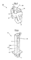
- FIG 3 shows an embodiment of a clip 30.
- the clip 30 has a foot 31 shaped like an anchor with flexible branches, for co-operating with the matching notches 21, 24 formed in the strip 20.
- the foot 31 supports a base 32 carrying a first portion in relief 33 and a second portion in relief 34 extending perpendicularly to each other so as to form a housing 35 in which the bottom edge of a plane element 3, 5 can be inserted.
- the plane element 3, 5 is inserted between the portions in relief 33 and 34 in the direction represented by arrow 36, and is then tilted so as to insert the first portion in relief 33 into a hole provided in the element 3, 5 so as to lock the plane elements 3, 5.
- FIG 4 shows an embodiment of an end abutment 40.
- the abutment 40 has a foot 41 shaped like an anchor with flexible branches, that is to co-operate with matching notches 21, 24 formed in the strip 20.
- the foot 41 supports a base 42 surmounted by a projection 43 having a top portion that includes two branches 43a, 43b that are spaced apart a little so as to form a slot 44 in which the plane elements 3, 5 can be inserted.
- Figure 5 shows the shape of the end 50 of the plane element 3, 5 having a projecting tab 51 for co-operating with the orifice 44 of the abutment 40.
- the end 50 includes a notch 52 that makes it easier to position the tab 51 relative to the abutment 40 and that enables the plane element to be locked by inserting a stud 45 of the abutment into the notch 52.
- Figure 6 is a perspective view showing the abutment 40 in place, secured to the strip 20, in which abutment there is inserted the tab 51 placed at the end 50 of the plane element 3, 5.
- the plane elements 3 or 5 are held in self-locking manner and are capable of withstanding shock and vibration at high intensity.
Landscapes
- Engineering & Computer Science (AREA)
- Microelectronics & Electronic Packaging (AREA)
- Mechanical Engineering (AREA)
- General Engineering & Computer Science (AREA)
- Support Of Aerials (AREA)
- Clamps And Clips (AREA)
Abstract
Description
- The present invention relates to a device for rapidly fastening and holding plane elements that are disposed perpendicularly to the surface of a strip in such a manner as to prevent any relative movement between a plane element and the strip. The invention is suitable for use in particular for fastening a printed circuit plate on an elongate support.
- The device of the invention is particularly intended for antennas comprising a carrier structure of elongate shape. Rows of individual radiating dipoles separated by screens are placed along the structure and connected to a feeder cable. The antennas are generally placed in open air and are subjected to weathering. It is therefore essential for the radiating elements they contain to be securely fastened and held so as to withstand the shocks and/or vibrations that might occur. Nevertheless, in order to make antenna fabrication less expensive, the plane elements carrying the radiating dipoles must be capable of being put into place quickly and easily using means that are inexpensive.
- The prior art discloses fastener systems for plane elements such as printed circuits.
- Document
EP-0 542 163 describes an anti-shock and anti-vibration device for fastening printed circuit plates to a support that includes grooves, with fastening being by means of a self-locking clamping device comprising a rail provided with a pin that co-operates with a slot carried by a compression strap, that device does not enable plates to be put into place quickly. - Devices are known that enable a printed circuit card to be withdrawn and put into place quickly by sliding in a groove in an elongate support. Such devices do not prevent the card from moving longitudinally.
- Devices are also known that are provided with abutments, possibly including fastener means for fastening the plane elements to the abutments. Such a device does not enable a plane element of great length to be held suitably. In particular, for an outdoor application that is subjected to hazards in the environment, in particular due to weather such as a storm, those devices are not capable of performing their holding function.
- An object of the present invention is to eliminate the drawbacks of the prior art by proposing a device for quickly fastening a plane element on a support, the device comprising a combination of a small number of parts, the parts being simple in shape and being made of material that is inexpensive, enabling plane elements to be fastened easily and quickly while ensuring that they are held regardless of the surrounding conditions.
- The present invention provides a device for fastening and holding a plane element, the device comprising an elongate strip supporting the plane element and at least one abutment placed at each end of the strip and including fastener means for fastening to the strip and locking means co-operating with a notch formed in the plane element, the device being characterized in that the abutments further include connection means co-operating with a tab of the plane element, and in that the device further includes at least one clip placed between the abutment and independent of the strip, the clip comprising fastener means for fastening to the strip and engagement means for engaging in an orifice of the plane element by tilting, so as to prevent any displacement of the plane element relative to the strip.
- In a first embodiment of the invention, the fastener means for fastening to the strip comprise a foot in the shape of an anchor suitable for co-operating with a notch formed in the strip.
- In a second embodiment of the invention, the engagement means of the clip received in the plane element comprises a first portion in relief suitable for co-operating with a hole formed in the plane element, and a second portion in relief extending perpendicularly to the first portion in relief to form a housing into which the plane element is inserted.
- In a third embodiment of the invention, the fastener means for fastening the plane elements to the abutment include an orifice carried by the abutment suitable for co-operating with a tab projecting from the end of the plane element.
- Preferably, the clips and the abutments are made of a plastics material presenting a certain degree of flexibility, such as a polypropylene, for example.
- Also preferably, the strip is made of a plastics material presenting a certain degree of rigidity, such as a polycarbonate, for example.
- The present invention also provides a method of fastening a plane element by means of a device comprising an elongate strip, at least one abutment at each end of the strip including fastener means for fastening to the strip, locking means co-operating with a notch formed in the plane element and connection means co-operating with a tab of the plane element, and at least one clip comprising fastener means for fastening to the strip and engagement means for engaging in an orifice of the plane element, the method being characterized in that it comprises the following steps:
- · fastening the abutment to the end of the strip;
- · engaging the plane element in the clips;
- · fastening the strip carrying the plane element in the clips; and
- · connecting the plane element to the abutment.
- In a first implementation of the invention, the plane element is inserted in a housing formed by first and second portions in relief of the clip, which portions are oriented perpendicularly to each other, after which the plane element is tilted so as to insert the first portion in relief of the clip into a hole pierced in the plane element.
- In a second implementation of the invention, the clips carrying the plane element are inserted in the strip in such a manner that the feet of the clips penetrate into the notches of the strip.
- In a third implementation of the invention, the plane element is connected to the abutment by inserting the tab projecting from the end of the plane element in an orifice in the abutment.
- The present invention also provides an antenna including a device as described above. The plane elements comprise printed circuits forming rows of dipoles and metallic screens. The circuits and the screens are disposed in parallel and in alternation, and they are fastened and held by the device of the invention.
- Other characteristics and advantages of the present invention appear on reading the following description of an embodiment, naturally given by way of non-limiting illustration, and from the accompanying drawings, in which:
- · Figure 1 is a fragmentary perspective view of an antenna including the device of the present invention;
- · Figures 2A and 2B show an embodiment of the strip of the device of the invention;
- · Figure 3 shows an embodiment of the clip of the device of the invention;
- · Figure 4 shows an embodiment of the abutment of the device of the invention;
- · Figure 5 shows an example of an end of the plane element suitable for co-operating with the abutment of Figure 4; and
- · Figure 6 is a fragmentary perspective view on a larger scale showing an antenna including the device of the present invention.
- In the embodiment of the invention shown in Figure 1, the antenna 1 comprises a
frame 2 having profiled longitudinal strips secured thereto carrying parallel printed circuit plates 3 carrying rows of unit dipoles 4 that are separated by flatmetallic screens 5. The dipoles are fed viaconnectors 6. - Figure 2A shows a
strip 20 seen from above, and Figure 2B shows thesame strip 20 seen in profile. Thestrip 20 has a first series of circularly-arcuate notches 21 formed in itstop portion 22 for receiving the bases of clips. In thebottom portion 23 there is disposed a second series ofnotches 24 in register with thenotches 21 of the first series. Thesenotches 24 include respective portions inrelief 25 forming springs in order to retain the clips once inserted. Thestrip 20 possessesfeet 26. - Figure 3 shows an embodiment of a clip 30. The clip 30 has a
foot 31 shaped like an anchor with flexible branches, for co-operating with thematching notches strip 20. Thefoot 31 supports abase 32 carrying a first portion inrelief 33 and a second portion inrelief 34 extending perpendicularly to each other so as to form ahousing 35 in which the bottom edge of aplane element 3, 5 can be inserted. Theplane element 3, 5 is inserted between the portions inrelief relief 33 into a hole provided in theelement 3, 5 so as to lock theplane elements 3, 5. - Figure 4 shows an embodiment of an
end abutment 40. Theabutment 40 has afoot 41 shaped like an anchor with flexible branches, that is to co-operate with matchingnotches strip 20. Thefoot 41 supports abase 42 surmounted by a projection 43 having a top portion that includes twobranches 43a, 43b that are spaced apart a little so as to form aslot 44 in which theplane elements 3, 5 can be inserted. - Figure 5 shows the shape of the
end 50 of theplane element 3, 5 having aprojecting tab 51 for co-operating with theorifice 44 of theabutment 40. Theend 50 includes anotch 52 that makes it easier to position thetab 51 relative to theabutment 40 and that enables the plane element to be locked by inserting astud 45 of the abutment into thenotch 52. - Figure 6 is a perspective view showing the
abutment 40 in place, secured to thestrip 20, in which abutment there is inserted thetab 51 placed at theend 50 of theplane element 3, 5. - It will be understood that by the combined action of the
abutment 40 and of the clips 30 secured to and interconnected by thestrip 20, theplane elements 3 or 5 are held in self-locking manner and are capable of withstanding shock and vibration at high intensity.
Claims (11)
- A device for fastening and holding a plane element (3, 5), the device comprising an elongate strip (20) supporting the plane element (3, 5, 50) and at least one abutment (40) placed at each end of the strip (20) and including fastener means (41) for fastening to the strip (20) and locking means (45) co-operating with a notch (52) formed in the plane element (3, 5), the device being characterized in that the abutments (40) further include connection means (43, 44) co-operating with a tab (51) of the plane element (3, 5), and in that the device further includes at least one clip (30) placed between the abutment (40) and independent of the strip (20), the clip comprising fastener means (31) for fastening to the strip (20) and engagement means (33, 34, 35) for engaging in an orifice of the plane element (3, 5) by tilting, so as to prevent any displacement of the plane element (3, 5) relative to the strip (20).
- A device according to claim 1, in which the fastener means for fastening to the strip (20) comprise a foot (31, 41) in the shape of an anchor suitable for co-operating with a notch (21, 24) formed in the strip (20).
- A device according to claim 1, in which the engagement means of the clip (30) received in the plane element (3, 5) comprise a first portion (33) in relief suitable for co-operating with a hole formed in the plane element (3, 5), and a second portion in relief (34) extending perpendicularly to the first portion in relief (33) to form a housing into which the plane element (3, 5) is inserted.
- A device according to claim 1, in which the fastener means for fastening the plane elements (3, 5) to the abutment (40) include an orifice (44) carried by the abutment (40) suitable for co-operating with a tab (51) projecting from the end of the plane element (3, 5).
- A device according to any one of claims 1 to 4, in which the clips (30) and the abutments (40) are made of polypropylene.
- A device according to any one of claims 1 to 4, in which the strip (20) is made of polycarbonate.
- A method of fastening a plane element (3, 5) by means of a device comprising an elongate strip (20), at least one abutment (40) at each end of the strip (20) including fastener means (41) for fastening to the strip (20), locking means (45) co-operating with a notch (52) formed in the plane element (3, 5) and connection means (43, 44) co-operating with a tab (51) of the plane element (3, 5), and at least one clip (30) comprising fastener means (31) for fastening to the strip (20) and engagement means (33, 34, 35) for engaging in an orifice of the plane element (3, 5), the method being characterized in that it comprises the following steps:· fastening the abutment (40) to the end of the strip (20);· engaging the plane element (3, 5) in the clips (30);· fastening the strip (20) carrying the plane element (3, 5) in the clips (30); and· connecting the plane element (3, 5) to the abutment.
- A method according to claim 7, in which the plane element (3, 5) is inserted in a housing (35) formed by first and second portion (33; 34) in relief of the clip (30), which portions are oriented perpendicularly to each other, after which the plane element (3, 5) is tilted so as to insert the first portion (33) in relief of the clip (30) into a hole pierced in the plane element (3, 5).
- A method according to claim 7, in which the clips (30) carrying the plane element (3, 5) are inserted in the strip (20) in such a manner that the feet (31) of the clips (30) penetrate into the notches (21, 24) of the strip (20).
- A method according to claim 7, in which the plane element (3, 5) is connected to the abutment (40) by inserting the tab (51) projecting from the end (50) of the plane element (3, 5) in an orifice (44) in the abutment (40).
- An antenna comprising a device according to any one of claims 1 to 4, characterized in that the plane elements (3, 5) comprise printed circuits (3) forming rows of dipoles (4), and metal screens (5), the circuits (3) and the screens (5) being disposed in parallel and in alternation.
Applications Claiming Priority (1)
| Application Number | Priority Date | Filing Date | Title |
|---|---|---|---|
| FR0653517A FR2905555A1 (en) | 2006-08-31 | 2006-08-31 | FIXING AND HOLDING OF PLANE ELEMENTS ON A SUPPORT |
Publications (1)
| Publication Number | Publication Date |
|---|---|
| EP1895822A1 true EP1895822A1 (en) | 2008-03-05 |
Family
ID=38006598
Family Applications (1)
| Application Number | Title | Priority Date | Filing Date |
|---|---|---|---|
| EP20070113811 Withdrawn EP1895822A1 (en) | 2006-08-31 | 2007-08-03 | A disposition for fastening and holding plane elements on a support |
Country Status (2)
| Country | Link |
|---|---|
| EP (1) | EP1895822A1 (en) |
| FR (1) | FR2905555A1 (en) |
Citations (6)
| Publication number | Priority date | Publication date | Assignee | Title |
|---|---|---|---|---|
| DE1903057U (en) * | 1964-04-28 | 1964-10-29 | V E B Funkwerk Erfurt | SECURING ELEMENT FOR PLATES INSERTED IN GUIDE RAILS. |
| US4019099A (en) * | 1976-01-15 | 1977-04-19 | Calabro Anthony Denis | Circuit board mounting device |
| DE8903958U1 (en) * | 1989-03-31 | 1989-05-18 | Siemens AG, 1000 Berlin und 8000 München | Device for guiding and holding printed circuit boards |
| US5805429A (en) * | 1994-06-10 | 1998-09-08 | Telefonaktiebolaget Lm Ericsson | Rail assembly |
| US6045386A (en) * | 1998-04-30 | 2000-04-04 | Micron Electronics, Inc. | Circuit board retaining device |
| WO2002051219A1 (en) * | 2000-12-20 | 2002-06-27 | Telefonaktiebolaget Lm Ericsson | Guide and support structure |
-
2006
- 2006-08-31 FR FR0653517A patent/FR2905555A1/en not_active Withdrawn
-
2007
- 2007-08-03 EP EP20070113811 patent/EP1895822A1/en not_active Withdrawn
Patent Citations (6)
| Publication number | Priority date | Publication date | Assignee | Title |
|---|---|---|---|---|
| DE1903057U (en) * | 1964-04-28 | 1964-10-29 | V E B Funkwerk Erfurt | SECURING ELEMENT FOR PLATES INSERTED IN GUIDE RAILS. |
| US4019099A (en) * | 1976-01-15 | 1977-04-19 | Calabro Anthony Denis | Circuit board mounting device |
| DE8903958U1 (en) * | 1989-03-31 | 1989-05-18 | Siemens AG, 1000 Berlin und 8000 München | Device for guiding and holding printed circuit boards |
| US5805429A (en) * | 1994-06-10 | 1998-09-08 | Telefonaktiebolaget Lm Ericsson | Rail assembly |
| US6045386A (en) * | 1998-04-30 | 2000-04-04 | Micron Electronics, Inc. | Circuit board retaining device |
| WO2002051219A1 (en) * | 2000-12-20 | 2002-06-27 | Telefonaktiebolaget Lm Ericsson | Guide and support structure |
Also Published As
| Publication number | Publication date |
|---|---|
| FR2905555A1 (en) | 2008-03-07 |
Similar Documents
| Publication | Publication Date | Title |
|---|---|---|
| CA2864477C (en) | Holder for a solar module | |
| US7226260B2 (en) | Sheet metal fastening clip | |
| US10469022B2 (en) | Photo-voltaic panel retention apparatus, system and method | |
| CN110036545B (en) | Suspension assembly | |
| US20210184626A1 (en) | Solar module mounting system | |
| ES2976770T3 (en) | Suspension assembly | |
| US9705447B2 (en) | Mounting clips for panel installation | |
| US7885077B2 (en) | Solderless heatsink anchor | |
| CN100587278C (en) | Fixing element and device with the same | |
| EP2369185A1 (en) | Clip | |
| US10030689B2 (en) | Mounting system for mounting of equipment in particular electrical appliances | |
| US9276518B2 (en) | Panel support structure | |
| US20090172930A1 (en) | Fixing Rail for an Elongate Object | |
| US20140124018A1 (en) | Photovoltaic Panel Racking System | |
| US20040049894A1 (en) | Sheet metal fastening clip | |
| US20040244156A1 (en) | Sheet metal fastening clip | |
| US20090111293A1 (en) | Retractable protection apparatus for electronic device pins | |
| EP1895822A1 (en) | A disposition for fastening and holding plane elements on a support | |
| EP4421408A1 (en) | Frame enhancer | |
| US7149094B2 (en) | Mounting assembly | |
| KR20160001812A (en) | Furring strip bracket | |
| KR20080097943A (en) | Fastening system for fastening plates in the enclosure | |
| US5313370A (en) | Component carrier for insertable circuit boards | |
| US20230093217A1 (en) | Antenna mount assembly | |
| US20050072714A1 (en) | Standard tray carrier for aligning trays |
Legal Events
| Date | Code | Title | Description |
|---|---|---|---|
| PUAI | Public reference made under article 153(3) epc to a published international application that has entered the european phase |
Free format text: ORIGINAL CODE: 0009012 |
|
| AK | Designated contracting states |
Kind code of ref document: A1 Designated state(s): AT BE BG CH CY CZ DE DK EE ES FI FR GB GR HU IE IS IT LI LT LU LV MC MT NL PL PT RO SE SI SK TR |
|
| AX | Request for extension of the european patent |
Extension state: AL BA HR MK YU |
|
| 17P | Request for examination filed |
Effective date: 20080905 |
|
| AKX | Designation fees paid |
Designated state(s): AT BE BG CH CY CZ DE DK EE ES FI FR GB GR HU IE IS IT LI LT LU LV MC MT NL PL PT RO SE SI SK TR |
|
| 17Q | First examination report despatched |
Effective date: 20081023 |
|
| GRAP | Despatch of communication of intention to grant a patent |
Free format text: ORIGINAL CODE: EPIDOSNIGR1 |
|
| STAA | Information on the status of an ep patent application or granted ep patent |
Free format text: STATUS: THE APPLICATION IS DEEMED TO BE WITHDRAWN |
|
| 18D | Application deemed to be withdrawn |
Effective date: 20091123 |