EP1895359A1 - Camera Module - Google Patents
Camera Module Download PDFInfo
- Publication number
- EP1895359A1 EP1895359A1 EP07115204A EP07115204A EP1895359A1 EP 1895359 A1 EP1895359 A1 EP 1895359A1 EP 07115204 A EP07115204 A EP 07115204A EP 07115204 A EP07115204 A EP 07115204A EP 1895359 A1 EP1895359 A1 EP 1895359A1
- Authority
- EP
- European Patent Office
- Prior art keywords
- holder
- annular portion
- inner annular
- leaf spring
- cylindrical end
- Prior art date
- Legal status (The legal status is an assumption and is not a legal conclusion. Google has not performed a legal analysis and makes no representation as to the accuracy of the status listed.)
- Withdrawn
Links
Images



Classifications
-
- G—PHYSICS
- G03—PHOTOGRAPHY; CINEMATOGRAPHY; ANALOGOUS TECHNIQUES USING WAVES OTHER THAN OPTICAL WAVES; ELECTROGRAPHY; HOLOGRAPHY
- G03B—APPARATUS OR ARRANGEMENTS FOR TAKING PHOTOGRAPHS OR FOR PROJECTING OR VIEWING THEM; APPARATUS OR ARRANGEMENTS EMPLOYING ANALOGOUS TECHNIQUES USING WAVES OTHER THAN OPTICAL WAVES; ACCESSORIES THEREFOR
- G03B3/00—Focusing arrangements of general interest for cameras, projectors or printers
- G03B3/10—Power-operated focusing
-
- H—ELECTRICITY
- H04—ELECTRIC COMMUNICATION TECHNIQUE
- H04N—PICTORIAL COMMUNICATION, e.g. TELEVISION
- H04N23/00—Cameras or camera modules comprising electronic image sensors; Control thereof
- H04N23/50—Constructional details
- H04N23/55—Optical parts specially adapted for electronic image sensors; Mounting thereof
-
- H—ELECTRICITY
- H04—ELECTRIC COMMUNICATION TECHNIQUE
- H04N—PICTORIAL COMMUNICATION, e.g. TELEVISION
- H04N23/00—Cameras or camera modules comprising electronic image sensors; Control thereof
- H04N23/57—Mechanical or electrical details of cameras or camera modules specially adapted for being embedded in other devices
-
- G—PHYSICS
- G02—OPTICS
- G02B—OPTICAL ELEMENTS, SYSTEMS OR APPARATUS
- G02B7/00—Mountings, adjusting means, or light-tight connections, for optical elements
- G02B7/02—Mountings, adjusting means, or light-tight connections, for optical elements for lenses
- G02B7/023—Mountings, adjusting means, or light-tight connections, for optical elements for lenses permitting adjustment
Definitions
- This invention relates to a camera module, and more specifically to a camera module that can be used in small-sized electronic apparatuses such as digital cameras, camera-equipped cellular phones and the like.
- a camera module having a function of displacing a lens unit in a direction of an optical axis of the lens unit is used in relatively small-sized digital cameras, camera-equipped cellular phones and the like.
- This function is used for providing an autofocus function and/or zoom function and the like, and is achieved by an interaction between a magnetic field generated by an electrical current flowing in a coil and a magnetic field generated by a yoke and magnets provided on the yoke.
- Such a camera module includes a barrel which holds the lens unit, a holder which houses the barrel therein, and a pair of leaf springs for supporting the holder so that the holder is displaceable in a direction of an optical axis of the lens unit.
- FIG.10 is an exploded perspective view of an autofocus actuator assembly 100 used in a conventional camera module for displacing a lens unit (not shown) in a direction of an optical axis thereof. It is to be noted that an imaging element (not shown) is provided below a base 111 of the actuator assembly 100.
- a holder 108 that houses a barrel (not shown) holding the lens unit is provided between a cover 101 and the base 111 so that the holder 108 is displaceable in a direction of an optical axis of the lens unit together with the lens unit.
- a ring -shaped inner annular portion 104b of an upper leaf spring 104 and a ring-shaped inner annular portion 110b of a lower leaf spring 110 are attached to the upper and lower cylindrical end portions of the holder 108, respectively, using an adhesive. Further, a ring-shaped outer annular portion 104a of the upper leaf spring 104 is attached to a top surface of a yoke 105 which is mounted on the base 111 and a ring-shaped outer annular portion 110a of the lower leaf spring 110 is attached to the base 111, respectively.
- Three bridge portions 104c are coupled between the outer annular portion 104a and the inner annular portion 104b of the upper leaf spring 104.
- three bridge portions 110c are coupled between the outer annular portion 110a and the inner annular portion 110b of the upper leaf spring 110.
- a plurality of magnets 106 are provided on the yoke 105 so as to produce a magnetic field.
- the yoke 105 has an axial bore 105a for receiving the holder 108.
- a coil 107 is provided around an outer periphery of the holder 108 so that the coil 7 is disposed in the magnetic field produced by the magnets and the yoke 105 in a state that the holder 108 is received in the axial bore 105a.
- a component denoted by the reference numeral 103 is a flexible printed circuit board used for supplying a current to the coil 107
- a component denoted by the reference numeral 102 is a stopper arranged above the upper surface of the inner annular portion of the upper leaf spring 104
- a component donated by the reference numeral 109 is a ring-shaped plate provided between the lower leaf spring 110 and the bottom surface of the yoke 105.
- the upper leaf spring 104 and the lower leaf spring 110 are bonded to the upper and lower cylindrical end portions of the holder 108, respectively, using an adhesive.
- a synthetic resin e.g. epoxy resin
- Such a synthetic resin is applied onto an end surface of each of the upper and lower cylindrical portions of the holder 108 by hand of a worker.
- the width of the end surface of the cylindrical end portion is extremely narrow. Therefore, an application of the synthetic resin to the end surface must be carried out carefully, and thus there is a problem in that a time required for the application operation cannot be shortened.
- the present invention has been made in view of the problems described above, and therefore it is an object of the present invention to provide a camera module in which leaf springs can be attached to a holder easily and reliably.
- the present invention is directed to a camera module, which comprises: a lens unit which constitutes an optical system of the camera module; a holder which houses the lens unit and is displaceable along an optical axis direction of the lens unit, the holder having a cylindrical shape having upper and lower cylindrical end portions; a coil provided on the holder; a yoke and magnets provided on the yoke for providing a magnetic field to the coil; upper and lower leaf springs for supporting the holder so that the holder is displaceable along an optical axis direction of the lens unit, each of the upper and lower springs including an outer annular portion, an inner annular portion provided inside the outer annular portion and attached to one of the cylindrical end portions of the holder, and a plurality of bridge portions coupled between the outer annular portion and the inner annular portion for displaceably supporting the inner annular portion with respect to the outer annular portion, each of the bridge portions having an inner annular portion side end portion coupled to an outer periphery of the inner annular portion;
- At least one of the inner annular portions of the upper and lower leaf springs is attached to the corresponding cylindrical end portion of the holder through an attachment means which is configured so that the inner annular portion is mechanically engaged with and attached to the cylindrical end portion of the holder.
- the camera module of the present invention having the above structure, since the bonding operating of the upper and lower spring for the upper and lower cylindrical end portions of the holder using a synthetic resin that was performed in the conventional camera module can be omitted, it is possible to shorten a time necessary for manufacturing a camera module.
- the inner annular portion of the lower leaf spring is attached to the lower cylindrical end portion of the holder through the attachment means, wherein the attachment means includes: a first means for engaging the inner annular portion of the lower leaf spring with the lower cylindrical end portion of the holder so that the inner annular portion does not rotate with respect to the holder in one of circumferential directions thereof, and a second means for holding the inner annular portion of the leaf spring against the holder so that the inner annular portion does not move in a direction parallel to the optical axis direction of the lens unit as well as does not rotate in the other circumferential direction in a state that the first means is in an engaged state.
- the lower cylindrical end portion of the holder is formed with a step so as to form a small cylindrical portion for receiving the inner annular portion and an end surface for supporting an upper surface of the inner annular portion
- the first means includes notches and tongues formed in the outer periphery of the inner annular portion of the lower leaf spring and protrusions formed on the end surface of the lower cylindrical end portion so as to be engageable with the respective tongues by rotating the lower leaf spring
- the second means include holding means provided on the lower cylindrical end portion of the holder for holding the inner annular portion side end parts of the respective bridge portions of the leaf spring from the bottom thereof in a state that the upper surface of the inner annular portion is supported on the end surface of the step and for restricting further rotation of the lower leaf spring in a state that the protrusions are engaged with the tongues.
- each of the protrusions has a slant surface for raising the tongue according to the rotation of the lower leaf spring
- each of the holding means includes a protruding portion formed on the outer circumferential surface of the lower cylindrical end portion and a holding arm horizontally protruding from a tip part of the protruding portion for holding the inner annular portion side end part of the bridge portion of the lower leaf spring.
- the inner annular portion of the upper leaf spring is attached to the upper cylindrical end portion of the holder through the attachment means, wherein the attachment means comprises a ring-shaped member detachably attached to the upper cylindrical end portion of the holder, and the ring-shaped member is configured so that that the inner annular portion of the upper leaf spring is fixedly held between an end surface of the upper cylindrical end portion of the holder and an inner surface of the ring-shaped member when the ring-shaped stopper is attached to the upper cylindrical end portion of the holder.
- the ring-shaped member has an inner circumferential surface, wherein the inner circumferential surface of the ring-shaped member is formed with a plurality of engaging means, and the lower cylindrical end portion of the holder has a plurality of engaged means to which the engaging means of the ring-shaped are engaged by rotating the ring-shaped member with respect to the holder.
- each of the engaging means includes a notch formed in the circumferential surface and a step provided in association with the notch
- each of the engaged means includes a protruding piece protruding upwardly from the upper cylindrical end portion of the holder and an engaging rib extending from a tip part of the protruding piece, wherein the notches receive the protruding pieces with the engaging ribs when the ring-shaped member is placed onto the upper end cylindrical portion of the holder, and then by rotating the ring-shaped member in a predetermined direction the engaging ribs of the holder are engaged with the respective steps of the ring-shaped member.
- the ring-shaped member is a stopper for restricting excessive displacement of the holder in an upward direction.
- a camera module according to an embodiment of the present invention will be described below with reference to the accompanying drawing.
- the camera module comprises: a lens unit (not shown) which constitutes an optical system of the camera module; a holder 8 which houses the lens unit and is displaceable along an optical axis direction of the lens unit, the holder 8 having a cylindrical shape having upper and lower cylindrical end portions 8a and 8b; a coil 7 provided on the holder 8; a yoke 5 and magnets 6 provided on the yoke 5 for providing a magnetic field to the coil 7; upper and lower leaf springs 20, 30 for supporting the holder 8 so that the holder 8 is displaceable along an optical axis direction of the lens unit, each of the upper and lower springs 20, 30 including an outer annular portion 20a (30a), an inner annular portion 20b (30b) provided inside the outer annular portion 20a, (30a) and attached to one of the cylindrical end portions 8a (8b) of the holder 8, and a plurality of bridge portions 20c (30c) coupled between the outer annular portion 20a (30a) and the inner annular portion 20b (30b) for dis
- At least one of the inner annular portions 20b (30b) of the upper and lower leaf springs 20, 30 is attached to the corresponding cylindrical end portion 8a, 8b of the holder 8 through an attachment means which is configured so that the inner annular portion (20b, 30b) is mechanically engaged with and attached to the cylindrical end portion (8a, 8b) of the holder 8.
- both the upper and lower leaf springs 20, 30 are attached to the respective cylindrical end portions 8a, 8b by means of the attachment means, respectively.
- at least one of the upper and lower springs 20, 30 may be attached to the corresponding cylindrical end portion by means of the attachment means.
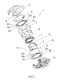
- an actuator assemble 1 of the camera module of the embodiment according to the present invention description is made with regard to an actuator assemble 1 of the camera module of the embodiment according to the present invention.
- an imaging element (not shown in the drawing) is disposed below the base 10.
- the holder 8 that houses the barrel (not shown) holding the lens unit is provided in a space defined between a cover 2 and the base 10 so that the holder 8 is displaceable in a direction of an optical axis of the lens unit.
- the inner annular portion 20b of the upper leaf spring 20 is attached between an upper end surface of a cylindrical end portion 8a of the holder 8 and a bottom surface of a stopper 3 which is a ring-shaped member of the present invention.
- the stopper 3 is provided for restricting upwardly excessive displacement of the holder 8 by the abutment with the bottom surface of the cover 2 when the holder 8 is largely displaced.
- the lower cylindrical end portion 8b of the holder 8 is formed with a step 8c to form an end surface 8d and a small cylindrical portion 8e.
- the inner annular portion 30b of the lower leaf spring 30 is attached to the step 8c in a state that an opening of the inner annular portion 30b is fitted onto the small cylindrical portion 8e of the holder 8.
- the plurality of magnets 6 are bonded to the inner surface of the yoke 5 so as to produce a magnetic field. Further, the coil 7 is provided around an outer periphery of the holder 8 so that the coil 7 is disposed in the magnetic field generated by the magnets 6 and the yoke 5.
- the yoke 7 has an axial bore 8a for receiving the holder 8.
- the holder 8 displaceably supported by the upper and lower leaf springs 20, 30 can be displaced through the axial bore 8a in a direction of an optical axis of the lens unit by supplying a current to the coil 7.
- a component denoted by the reference numeral 4 is a flexible printed circuit board used for supplying a current to the coil 7, and a component denoted by the reference numeral 9 is a plate provided between the lower leaf spring 30 and the bottom surface of the yoke 5.
- the lower leaf spring 30 is formed from a thin metal plate made of beryllium copper through a punching process and has the ring-shaped outer annular portion 30a and the ring-shaped inner annular portion 30b which is concentrically provided inside the outer annular portion 30a through a predetermined annular spacing 30f.
- the inner annular portion 30b is displaceably supported by the outer annular portion 30a through the bridge portions 30c.
- Each of the bridge portions 30c has an elongated arc-shape, and positioned inside the annular spacing 30f so that it extends along the inner periphery of the outer annular portion 30a and the outer periphery of the inner annular portion 30b through a predetermined angle.
- each of the bridge portions 30c has the outer annular portion side base part coupled to the inner periphery of the outer annular portion 30a and the inner annular portion side base part 30d which is coupled to the outer periphery of the inner annular portion 30b.
- notches 31 In the inner periphery of the inner annular portion 30b, there are formed three notches 31 at locations near the respective inner annular portion side base parts 30d. Further, tongues 32 are also formed in the inner periphery of the inner annular portion 30b adjacent to the respective notches 31. The notches 31 and tongues 32 function as engaging means.
- the holder 8 is a cylindrical member 8 made of a synthetic resin. As described above, the holder 8 has the lower end cylindrical portion 8b, and the step 8c is formed around the lower end cylindrical portion 8b to form the end surface 8d and the small cylindrical portion 8e. On the end surface 8d of the step 8c, three protrusions 30 which are engageable with the notches 31 are formed in a protruding manner (these protrusions 30 constitute "engaged means"). Each of the protrusions 80 is formed into a wedge shape having a slant surface 80a (see FIG. 5). Further, on the outer circumferential surface of the lower end cylindrical portion 8b, there are formed three protruding portions 81 through the same spacing so as to protrude outwardly.
- a holding arm 83 for holding the inner annular portion side base part 30d of the bridge portion 30c of the lower leaf spring 30 in an optical axis direction of the lens unit.
- the holding arm 83 horizontally protrudes from a tip part of the protruding portion 81 and has a holding surface 84 for holding the upper surface of the inner annular portion side base part 30d of the bridge portion 30c (see FIG. 3) .
- the protruding portions 81 and the holding arms 83 constitute holding means which serves as a holding means of the present invention in cooperation with the end surfaced 8d of the step 8c of the holder 8.
- projections denoted by the reference numeral 82 are contacting bosses against the base 10.
- the inner annular portion 30b is fitted onto the small cylindrical portion 8e of the step 8c of the holder 8 in a state that the upper surface of the inner annular portion is supported by the end surface 8d.
- the lower leaf spring 30 is rotated in a direction indicated by the arrow in FIG. 3.
- the upper surface of the inner annular portion side base part 30d of the bridge portion 30c is first held by the holding surface 84 of the holding arm 83 of the protruding portion 81 of the holder 8 so that displacement of the inner annular portion 30b in the optical axis direction is restricted.
- each of the tongues 32 of the lower leaf spring 30 rides on the slant surface 80a of the corresponding protrusion 80 which protrudes from the end surface 8d of the step 8c. At this time, the tongue 32 and a part of the inner annular portion 30b near the tongue 32 is slightly deformed in a flex manner.
- the tongue 32 rides out of the protrusion 80 completely.
- the protrusion 80 is positioned inside the notch 31 in a state that the side portion of the tongue 32 and the side portion of the protrusion 80 is in abutment with each other, thereby restricting rotation of the lower spring 30 in an opposite rotation direction.
- the reason why the notch 31 and the tongue 32 are formed near the inner annular portion side base part 30d of the bridge portion 30c is to close an engagement position by the inner annular portion side base part 30d of the bridge portion 30c and the holding arm 83 to an engagement position by the notch 31 and the protrusion 80. Namely, by effectively adding an engagement force of the engagement position by the inner annular portion side base part 30d of the bridge portion 30c and the holding arm 83 in the optical axis direction to an engagement force of the engagement position by the notch 31 and the protrusion 80, it is possible to make difficult that the protrusion 80 comes out of the notch 31.
- the notches 31 and the tongues 32 of the inner annular portion 30b of the upper leaf spring 30 and the protrusions 80 formed on the end surface 8d of the holder 8 constitute a first means of the attachment means for engaging the inner annular portion 30b of the lower leaf spring 30 with the lower cylindrical end portion 8b of the holder 8 so that the inner annular portion 30b does not rotate with respect to the holder 8 in one of circumferential directions thereof.
- the protruding portions 81 and the holding arms 83 in cooperation with the end surface 8d of the step 8c of the holder 8 constitute a second means of the attachment means for holding the inner annular portion 30b of the lower leaf spring 30 against the holder 8 so that the inner annular portion does not move in a direction parallel to the optical axis direction of the lens unit as well as does not rotate in the other circumferential direction in a state that the first means is in an engaged state.
- the upper leaf spring 20 is attached to the holder 8 by means of the attachment means. Further, please note that in FIG. 6 to FIG. 9, the upper leaf spring 20 is not shown in these drawings for clearly showing the engagement state between the stopper 3 and the holder 8. In the actual product, the inner annular portion 20b of the upper spring 20 is fixedly held between the bottom surface 3b of the stopper 3 (see FIG. 7) and the end surface of the upper cylindrical end portion 8a of the holder 8.
- the upper leaf spring 20 has substantially the same structure as the lower leaf spring 30 (see FIG. 1). Specifically, the upper leaf spring 20 is formed from a thin metal plate made of beryllium copper through a punching process, and has the ring-shaped outer annular portion 20a and the ring-shaped inner annular portion 20b which is concentrically provided inside the outer annular portion 20a through a predetermined annular spacing 20f. The inner annular portion 20b is supported by the outer annular portion 20a through the bridge portions 20c.
- Each of the bridge portions 20c has an elongated are-shape, and positioned inside the annular spacing 20f so that it extends along the inner periphery of the outer annular portion 20a and the outer periphery of the inner annular portion 20b through a predetermined angle.
- the stopper 3 is a ring-shaped member made of a synthetic resin. And, as described above, the stopper 3 is provided for restricting upwardly excessive displacement of the holder 8 by the abutment with the bottom surface of the cover 2 when the holder is largely displaced. As described below, the stopper 3 is adapted to be engaged with the upper end cylindrical portion 8a of the holder 8 for fixedly attaching the upper leaf spring 20 to the holder 8.
- the stopper 3 has an inner circumferential surface 3a in which three notches 3c are formed. Further, on the inner circumferential surface 3a the stopper 3, three steps 3d are formed in association with the respective notches 3c (see FIG. 7).
- the notches 3c and the steps 3d of the stopper 3 constitute engaging means of the present invention (that is, the engaging means of the ring-shaped member of the present invention..
- each of the protruding pieces 88 includes an engaging rib 89 extending horizontally from a tip part of the protruding piece 88.
- the protruding pieces 88 and engaging ribs 89 constitute engaged means of the present invention.
- the inner annular portion 20b of the upper leaf spring 20 is placed on the end surface of the upper cylindrical end portion 8a of the holder 8. Then, as shown in FIG. 7, the stopper 3 is placed onto the holder 8 from the upper side of the inner annular portion 20b of the upper leaf spring 20 which has been placed on the end surface of the upper cylindrical end portion 8a of the holder 8 so that the protruding pieces 88 with the engaging ribs 89 are received in the respective notches 3c of the stopper 3 with avoiding contact with the steps 3d. Next, the stopper 3 is rotated in a direction shown by the arrow in FIG. 8.
- each engaging rib 89 is riding on an upper surface of the corresponding step 3d of the stopper 3.
- each engaging rib 89 is completely engaged with the corresponding step 3d.
- some portions of the stopper 3 are bonded to the holder 8 with a synthetic resin (adhesive) so that the stopper 3 cannot be rotated, In this way, the upper leaf spring 20 is fixedly held between the stopper 3 and the holder 8.
- this partial bonding is different from the bonding carried out in the conventional camera module where the upper leaf spring 20 is directly bonded to the holder 8 using an adhesive.
- the attachment means comprises the stopper 3 (ring-shaped member) detachably attached to the upper cylindrical end portion 8a of the holder 8, and the stopper 3 is configured so that that the inner annular portion 20a of the upper leaf spring 20 is fixedly held between an end surface of the upper cylindrical end portion 8a of the holder 8 and an inner surface of the stopper 3 when the stopper 3 is attached to the upper cylindrical end portion 8a of the holder 8.
- the stopper 3 has plurality of engaging means formed on the inner circumferential surface thereof, and the lower cylindrical end portion 8a of the holder 8 has a plurality of engaged means to which the engaging means of the stopper 3 are engaged by rotating the stopper 3.
- the engaging means includes the notches 3c formed in the circumferential surface 3a of the stopper 3 and steps 3d provided in association with the respective notches 3c
- the engaged means includes protruding pieces protruding upwardly from the upper cylindrical end portion 8a of the holder 8 and engaging ribs 89 extending from tip portions of the respective protruding pieces 88, wherein the notches receive the respective protruding pieces 88 with the engaging ribs 89 when the stopper 3 is placed onto the upper end cylindrical portion of the holder 8, and then by rotating the stopper 3 in a predetermined direction the engaging ribs 89 are engaged with the respective steps 3d.
- the lower leaf spring 30 can be fixedly attached to the holder 8 only by rotating the lower leaf spring 30 with respect to the holder 8 in a state that the inner annular portion 30b of the lower spring 30 is fitted onto the small cylindrical portion 8e of the step portion 8c and supported on the end surface 8d. Therefore, since the bonding operating using a synthetic resin that was performed in the conventional camera module can be omitted, it is possible to shorten a time necessary for manufacturing a camera module. Further, since the lower spring 30 can also be attached to the holder 8 without using an adhesive, it is possible to prevent the lower spring 30 from being peeled off due to an imperfect bonding state thereof.
- the upper leaf spring 20 can also be fixedly attached to the holder 8 only by rotating the stopper 3 with respect to the holder 8 in a state that the inner annular portion 20b is held between the stopper 3 and the end surface of the upper cylindrical end portion 8a of the holder 8. Therefore, since the bonding operating using a synthetic resin that was performed in the conventional camera module can also be omitted, it is possible to shorten a time necessary for manufacturing a camera module. Further, since the inner annular portion 20b is held between the stopper 3 and the end surface of the upper cylindrical end portion 8a of the holder 8, it is not necessary to apply rotational force directly to the upper leaf spring 20 which is made of a thin metal plate when it is attached to the holder 8. Therefore, it is possible to prevent stress deformation is caused in the upper leaf spring 20 during the attachment operation thereof.
- the stopper 3 which is provided for restricting excessive displacement of the holder 8 is used as the ring-shaped member for attaching the upper leaf spring 20, no additional part is required and thus a number of parts is not increased.
Landscapes
- Engineering & Computer Science (AREA)
- Multimedia (AREA)
- Signal Processing (AREA)
- Physics & Mathematics (AREA)
- General Physics & Mathematics (AREA)
- Lens Barrels (AREA)
- Studio Devices (AREA)
Abstract
Description
- This invention relates to a camera module, and more specifically to a camera module that can be used in small-sized electronic apparatuses such as digital cameras, camera-equipped cellular phones and the like.
- A camera module having a function of displacing a lens unit in a direction of an optical axis of the lens unit is used in relatively small-sized digital cameras, camera-equipped cellular phones and the like. This function is used for providing an autofocus function and/or zoom function and the like, and is achieved by an interaction between a magnetic field generated by an electrical current flowing in a coil and a magnetic field generated by a yoke and magnets provided on the yoke.
- Such a camera module includes a barrel which holds the lens unit, a holder which houses the barrel therein, and a pair of leaf springs for supporting the holder so that the holder is displaceable in a direction of an optical axis of the lens unit.
- FIG.10 is an exploded perspective view of an
autofocus actuator assembly 100 used in a conventional camera module for displacing a lens unit (not shown) in a direction of an optical axis thereof. It is to be noted that an imaging element (not shown) is provided below abase 111 of theactuator assembly 100. - A
holder 108 that houses a barrel (not shown) holding the lens unit is provided between acover 101 and thebase 111 so that theholder 108 is displaceable in a direction of an optical axis of the lens unit together with the lens unit. - A ring -shaped inner
annular portion 104b of anupper leaf spring 104 and a ring-shaped innerannular portion 110b of alower leaf spring 110 are attached to the upper and lower cylindrical end portions of theholder 108, respectively, using an adhesive. Further, a ring-shaped outerannular portion 104a of theupper leaf spring 104 is attached to a top surface of ayoke 105 which is mounted on thebase 111 and a ring-shaped outerannular portion 110a of thelower leaf spring 110 is attached to thebase 111, respectively. - Three
bridge portions 104c are coupled between the outerannular portion 104a and the innerannular portion 104b of theupper leaf spring 104. As is the same with theupper leaf spring 104, threebridge portions 110c are coupled between the outerannular portion 110a and the innerannular portion 110b of theupper leaf spring 110. By resilient deformation of the respective threebridge portions holder 108 can be displaced in a direction of an optical axis of the lens unit. - A plurality of
magnets 106 are provided on theyoke 105 so as to produce a magnetic field. Theyoke 105 has anaxial bore 105a for receiving theholder 108. Further, acoil 107 is provided around an outer periphery of theholder 108 so that thecoil 7 is disposed in the magnetic field produced by the magnets and theyoke 105 in a state that theholder 108 is received in theaxial bore 105a. By supplying a current to thecoil 107 to generate a magnetic field, theholder 108 can be displaced in a direction of an optical axis of the lens unit by a driving force generated by the interaction of the magnetic fields. In this regard, it is to be noted that a component denoted by thereference numeral 103 is a flexible printed circuit board used for supplying a current to thecoil 107, a component denoted by thereference numeral 102 is a stopper arranged above the upper surface of the inner annular portion of theupper leaf spring 104, and a component donated by thereference numeral 109 is a ring-shaped plate provided between thelower leaf spring 110 and the bottom surface of theyoke 105. - It is to be noted that an actuator assembly similar to the
actuator assembly 100 having suchupper leaf spring 104 andlower leaf spring 110 described above is disclosed inJP-A-No.2004-280031 - As described above, the
upper leaf spring 104 and thelower leaf spring 110 are bonded to the upper and lower cylindrical end portions of theholder 108, respectively, using an adhesive. In this case, a synthetic resin (e.g. epoxy resin) is used as the adhesive. Such a synthetic resin is applied onto an end surface of each of the upper and lower cylindrical portions of theholder 108 by hand of a worker. However, the width of the end surface of the cylindrical end portion is extremely narrow. Therefore, an application of the synthetic resin to the end surface must be carried out carefully, and thus there is a problem in that a time required for the application operation cannot be shortened. Further, an additional time is required for waiting the hardening of the applied synthetic resin, that is, it is necessary to leave theholder 108 to which the synthetic resin has been applied as it is for a certain period pf time after completion of the application of the synthetic resin. This leads to another problem in that a time required for manufacturing the camera module cannot be shortened. - Furthermore, in the case where a bonding area, that is an area of the end surface of the holder is extremely small, or in the case where a bonding condition of the synthetic resin against the inner annular portion of the leaf spring is not sufficient, it is not possible to ensure a sufficient bonding strength therebetween. In such a case, there is a problem in that the
upper leaf spring 104 and/or thelower leaf spring 110 may be partially peeled off from theholder 108 due to the reduced bonding force in the event that the electronic apparatus equipped with the camera module is dropped by accident. - The present invention has been made in view of the problems described above, and therefore it is an object of the present invention to provide a camera module in which leaf springs can be attached to a holder easily and reliably.
- In order to achieve the object, the present invention is directed to a camera module, which comprises: a lens unit which constitutes an optical system of the camera module; a holder which houses the lens unit and is displaceable along an optical axis direction of the lens unit, the holder having a cylindrical shape having upper and lower cylindrical end portions; a coil provided on the holder; a yoke and magnets provided on the yoke for providing a magnetic field to the coil; upper and lower leaf springs for supporting the holder so that the holder is displaceable along an optical axis direction of the lens unit, each of the upper and lower springs including an outer annular portion, an inner annular portion provided inside the outer annular portion and attached to one of the cylindrical end portions of the holder, and a plurality of bridge portions coupled between the outer annular portion and the inner annular portion for displaceably supporting the inner annular portion with respect to the outer annular portion, each of the bridge portions having an inner annular portion side end portion coupled to an outer periphery of the inner annular portion; and an imaging element provided below the lens unit. In this camera module, at least one of the inner annular portions of the upper and lower leaf springs is attached to the corresponding cylindrical end portion of the holder through an attachment means which is configured so that the inner annular portion is mechanically engaged with and attached to the cylindrical end portion of the holder.
- According to the camera module of the present invention having the above structure, since the bonding operating of the upper and lower spring for the upper and lower cylindrical end portions of the holder using a synthetic resin that was performed in the conventional camera module can be omitted, it is possible to shorten a time necessary for manufacturing a camera module.
- In the camera module of the present invention, it is preferred that the inner annular portion of the lower leaf spring is attached to the lower cylindrical end portion of the holder through the attachment means, wherein the attachment means includes: a first means for engaging the inner annular portion of the lower leaf spring with the lower cylindrical end portion of the holder so that the inner annular portion does not rotate with respect to the holder in one of circumferential directions thereof, and
a second means for holding the inner annular portion of the leaf spring against the holder so that the inner annular portion does not move in a direction parallel to the optical axis direction of the lens unit as well as does not rotate in the other circumferential direction in a state that the first means is in an engaged state. - Further, in the camera module of the present invention, it is preferred that the lower cylindrical end portion of the holder is formed with a step so as to form a small cylindrical portion for receiving the inner annular portion and an end surface for supporting an upper surface of the inner annular portion, wherein the first means includes notches and tongues formed in the outer periphery of the inner annular portion of the lower leaf spring and protrusions formed on the end surface of the lower cylindrical end portion so as to be engageable with the respective tongues by rotating the lower leaf spring, and wherein the second means include holding means provided on the lower cylindrical end portion of the holder for holding the inner annular portion side end parts of the respective bridge portions of the leaf spring from the bottom thereof in a state that the upper surface of the inner annular portion is supported on the end surface of the step and for restricting further rotation of the lower leaf spring in a state that the protrusions are engaged with the tongues.
- Furthermore, in the camera module of the present invention, it is preferred that wherein each of the protrusions has a slant surface for raising the tongue according to the rotation of the lower leaf spring, and each of the holding means includes a protruding portion formed on the outer circumferential surface of the lower cylindrical end portion and a holding arm horizontally protruding from a tip part of the protruding portion for holding the inner annular portion side end part of the bridge portion of the lower leaf spring.
- Furthermore, in the camera module of the present invention, it is preferred that the inner annular portion of the upper leaf spring is attached to the upper cylindrical end portion of the holder through the attachment means, wherein the attachment means comprises a ring-shaped member detachably attached to the upper cylindrical end portion of the holder, and the ring-shaped member is configured so that that the inner annular portion of the upper leaf spring is fixedly held between an end surface of the upper cylindrical end portion of the holder and an inner surface of the ring-shaped member when the ring-shaped stopper is attached to the upper cylindrical end portion of the holder.
- Furthermore, in the camera module of the present invention, it is preferred that the ring-shaped member has an inner circumferential surface, wherein the inner circumferential surface of the ring-shaped member is formed with a plurality of engaging means, and the lower cylindrical end portion of the holder has a plurality of engaged means to which the engaging means of the ring-shaped are engaged by rotating the ring-shaped member with respect to the holder.
- Furthermore, in the camera module of the present invention, it is preferred that each of the engaging means includes a notch formed in the circumferential surface and a step provided in association with the notch, and each of the engaged means includes a protruding piece protruding upwardly from the upper cylindrical end portion of the holder and an engaging rib extending from a tip part of the protruding piece, wherein the notches receive the protruding pieces with the engaging ribs when the ring-shaped member is placed onto the upper end cylindrical portion of the holder, and then by rotating the ring-shaped member in a predetermined direction the engaging ribs of the holder are engaged with the respective steps of the ring-shaped member.
- Moreover, in the camera module of the present invention, it is preferred that the ring-shaped member is a stopper for restricting excessive displacement of the holder in an upward direction.
- The above and other objects, features and advantages of the present invention will be apparent from the following description when taken in conjunction with the accompanying drawings which illustrate preferred embodiments of the present invention by way of example.
-
- FIG. 1 is an exploded perspective view of an actuator assembly 1 of a camera module of an embodiment according to the present invention.
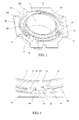
- FIG. 2 is a perspective view which shows an engagement state of a
holder 8 and alower leaf spring 30 of the actuator assembly 1 of the camera module shown in FIG. 1. - FIG. 3 is an enlarged perspective view which shows a state before the engagement of the
holder 8 and thelower leaf spring 30 of the actuator assembly 1 of the camera module shown in FIG. 1. - FIG. 4 is an enlarged perspective view which shows a state that the engagement of the
holder 8 and thelower leaf spring 30 is established in the actuator assembly 1 of the camera module shown in FIG. 1. - FIG. 5 is an enlarged perspective view which shows a state between a
protrusion 80 of theholder 8 and anotch 31 of thelower leaf spring 30 of the actuator assembly 1 of the camera module shown in FIG. 1. - FIG. 6 is a perspective view which shows a state that a
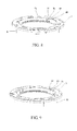
stopper 3 is in engagement with theholder 8, wherein this figure shows the engagement state therebetween viewed from the side of an uppercylindrical end portion 8a of theholder 8. Note that anupper leaf spring 20 is omitted from the figure for the purpose of clearly showing the engagement state between thestopper 3 and theholder 8. - FIG. 7 is an enlarged perspective view which shows a state before the engagement of the
holder 8 and theupper leaf spring 20 of the actuator assembly 1 of the camera module shown in FIG. 1. Note that that theupper leaf spring 20 is omitted from the figure for the purpose of clearly showing the engagement state between thestopper 3 and theholder 8. - FIG. 8 is an enlarged perspective view which shows a state just before the engagement of the
holder 8 and theupper leaf spring 20 of the actuator assembly 1 of the camera module shown in FIG. 1. Note that that theupper leaf spring 20 is omitted from the figure for the purpose of clearly showing the engagement state between thestopper 3 and theholder 8. - FIG. 9 is an enlarged perspective view which shows a state that the engagement of the
holder 8 and theupper leaf spring 20 is established in the actuator assembly 1 of the camera module shown in FIG. 1. Note that that theupper leaf spring 20 is omitted from the figure for the purpose of clearly showing the engagement state between thestopper 3 and theholder 8. - FIG. 10 is an exploded perspective view of an
actuator assembly 100 of a conventional camera module. - A camera module according to an embodiment of the present invention will be described below with reference to the accompanying drawing.
- The camera module according to the embodiment comprises: a lens unit (not shown) which constitutes an optical system of the camera module; a
holder 8 which houses the lens unit and is displaceable along an optical axis direction of the lens unit, theholder 8 having a cylindrical shape having upper and lowercylindrical end portions coil 7 provided on theholder 8; ayoke 5 andmagnets 6 provided on theyoke 5 for providing a magnetic field to thecoil 7; upper andlower leaf springs holder 8 so that theholder 8 is displaceable along an optical axis direction of the lens unit, each of the upper andlower springs annular portion 20a (30a), an innerannular portion 20b (30b) provided inside the outerannular portion 20a, (30a) and attached to one of thecylindrical end portions 8a (8b) of theholder 8, and a plurality ofbridge portions 20c (30c) coupled between the outerannular portion 20a (30a) and the innerannular portion 20b (30b) for displaceably supporting the innerannular portion 20b (30b) with respect to the outerannular portion 20a (30a), each of thebridge portions 20c (30c) having an inner annular portion side end portion 20d (30d) coupled to an outer periphery of the innerannular portion 20b (30b); and an imaging element provided below the lens unit. In this camera module, at least one of the innerannular portions 20b (30b) of the upper andlower leaf springs cylindrical end portion holder 8 through an attachment means which is configured so that the inner annular portion (20b, 30b) is mechanically engaged with and attached to the cylindrical end portion (8a, 8b) of theholder 8. In the following description, both the upper andlower leaf springs cylindrical end portions lower springs - Hereinbelow, with reference to FIG. 1, description is made with regard to an actuator assemble 1 of the camera module of the embodiment according to the present invention. In this regard, it is to be noted that an imaging element (not shown in the drawing) is disposed below the
base 10. - The
holder 8 that houses the barrel (not shown) holding the lens unit is provided in a space defined between acover 2 and the base 10 so that theholder 8 is displaceable in a direction of an optical axis of the lens unit. - As described below, the inner
annular portion 20b of theupper leaf spring 20 is attached between an upper end surface of acylindrical end portion 8a of theholder 8 and a bottom surface of astopper 3 which is a ring-shaped member of the present invention. Thestopper 3 is provided for restricting upwardly excessive displacement of theholder 8 by the abutment with the bottom surface of thecover 2 when theholder 8 is largely displaced. Further, as described below, the lowercylindrical end portion 8b of theholder 8 is formed with astep 8c to form anend surface 8d and a smallcylindrical portion 8e. The innerannular portion 30b of thelower leaf spring 30 is attached to thestep 8c in a state that an opening of the innerannular portion 30b is fitted onto the smallcylindrical portion 8e of theholder 8. - The plurality of
magnets 6 are bonded to the inner surface of theyoke 5 so as to produce a magnetic field. Further, thecoil 7 is provided around an outer periphery of theholder 8 so that thecoil 7 is disposed in the magnetic field generated by themagnets 6 and theyoke 5. Theyoke 7 has anaxial bore 8a for receiving theholder 8. Theholder 8 displaceably supported by the upper andlower leaf springs axial bore 8a in a direction of an optical axis of the lens unit by supplying a current to thecoil 7. It is noted that a component denoted by the reference numeral 4 is a flexible printed circuit board used for supplying a current to thecoil 7, and a component denoted by thereference numeral 9 is a plate provided between thelower leaf spring 30 and the bottom surface of theyoke 5. - Next, with reference to FIG. 2 to FIG. 5, detailed description will be made with regard to the
lower leaf spring 30 and theholder 8. In this regard, please note that thelower leaf spring 30 is attached to theholder 8 by means of the attachment means. - The
lower leaf spring 30 is formed from a thin metal plate made of beryllium copper through a punching process and has the ring-shaped outerannular portion 30a and the ring-shaped innerannular portion 30b which is concentrically provided inside the outerannular portion 30a through a predeterminedannular spacing 30f. The innerannular portion 30b is displaceably supported by the outerannular portion 30a through thebridge portions 30c. Each of thebridge portions 30c has an elongated arc-shape, and positioned inside theannular spacing 30f so that it extends along the inner periphery of the outerannular portion 30a and the outer periphery of the innerannular portion 30b through a predetermined angle. Further, each of thebridge portions 30c has the outer annular portion side base part coupled to the inner periphery of the outerannular portion 30a and the inner annular portionside base part 30d which is coupled to the outer periphery of the innerannular portion 30b. - In the inner periphery of the inner
annular portion 30b, there are formed threenotches 31 at locations near the respective inner annular portionside base parts 30d. Further,tongues 32 are also formed in the inner periphery of the innerannular portion 30b adjacent to therespective notches 31. Thenotches 31 andtongues 32 function as engaging means. - The
holder 8 is acylindrical member 8 made of a synthetic resin. As described above, theholder 8 has the lower endcylindrical portion 8b, and thestep 8c is formed around the lower endcylindrical portion 8b to form theend surface 8d and the smallcylindrical portion 8e. On theend surface 8d of thestep 8c, threeprotrusions 30 which are engageable with thenotches 31 are formed in a protruding manner (theseprotrusions 30 constitute "engaged means"). Each of theprotrusions 80 is formed into a wedge shape having aslant surface 80a (see FIG. 5). Further, on the outer circumferential surface of the lower endcylindrical portion 8b, there are formed three protrudingportions 81 through the same spacing so as to protrude outwardly. On the side potion of each of these protrudingportions 81, there is formed a holdingarm 83 for holding the inner annular portionside base part 30d of thebridge portion 30c of thelower leaf spring 30 in an optical axis direction of the lens unit. The holdingarm 83 horizontally protrudes from a tip part of the protrudingportion 81 and has a holdingsurface 84 for holding the upper surface of the inner annular portionside base part 30d of thebridge portion 30c (see FIG. 3) . The protrudingportions 81 and the holdingarms 83 constitute holding means which serves as a holding means of the present invention in cooperation with the end surfaced 8d of thestep 8c of theholder 8. In this regard, it is to be noted that projections denoted by thereference numeral 82 are contacting bosses against thebase 10. - Next, description is made with regard to the operations for attaching the lower leaf spring to the
holder 8. - First, as shown in FIG. 3, the inner
annular portion 30b is fitted onto the smallcylindrical portion 8e of thestep 8c of theholder 8 in a state that the upper surface of the inner annular portion is supported by theend surface 8d. Then, thelower leaf spring 30 is rotated in a direction indicated by the arrow in FIG. 3. According to the rotation of thelower leaf spring 30, the upper surface of the inner annular portionside base part 30d of thebridge portion 30c is first held by the holdingsurface 84 of the holdingarm 83 of the protrudingportion 81 of theholder 8 so that displacement of the innerannular portion 30b in the optical axis direction is restricted. - When the lower spring is further rotated, each of the
tongues 32 of thelower leaf spring 30 rides on theslant surface 80a of the correspondingprotrusion 80 which protrudes from theend surface 8d of thestep 8c. At this time, thetongue 32 and a part of the innerannular portion 30b near thetongue 32 is slightly deformed in a flex manner. - When the lower spring is further rotated, the
tongue 32 rides out of theprotrusion 80 completely. In this state, as shown in FIG. 4 and FIG. 5, theprotrusion 80 is positioned inside thenotch 31 in a state that the side portion of thetongue 32 and the side portion of theprotrusion 80 is in abutment with each other, thereby restricting rotation of thelower spring 30 in an opposite rotation direction. - On the other hand, as shown in FIG. 4, when the
tongue 32 has ridden over theprotrusion 80 and theprotrusion 80 has been positioned inside the notch. 81, the inner annular portionside base part 30d of thebridge portion 30c abuts against aside wall 81a of the protrudingportion 81, thereby restricting further rotation of thelower leaf spring 30. In this sate, rotation of thelower spring 30 with respect to theholder 8 is completely restricted in both the circumferential directions, and displacement of the innerannular portion 30b of thelower leaf spring 30 in the optical axis direction is also restricted by the holdingarm 83 and theend surface 8d of thestep 8c. With this result, thelower leaf spring 30 is fixedly attached to theholder 8. - In this regard, please note that the reason why the
notch 31 and thetongue 32 are formed near the inner annular portionside base part 30d of thebridge portion 30c is to close an engagement position by the inner annular portionside base part 30d of thebridge portion 30c and the holdingarm 83 to an engagement position by thenotch 31 and theprotrusion 80. Namely, by effectively adding an engagement force of the engagement position by the inner annular portionside base part 30d of thebridge portion 30c and the holdingarm 83 in the optical axis direction to an engagement force of the engagement position by thenotch 31 and theprotrusion 80, it is possible to make difficult that theprotrusion 80 comes out of thenotch 31. - In this embodiment described above, the
notches 31 and thetongues 32 of the innerannular portion 30b of theupper leaf spring 30 and theprotrusions 80 formed on theend surface 8d of theholder 8 constitute a first means of the attachment means for engaging the innerannular portion 30b of thelower leaf spring 30 with the lowercylindrical end portion 8b of theholder 8 so that the innerannular portion 30b does not rotate with respect to theholder 8 in one of circumferential directions thereof. Further, the protrudingportions 81 and the holdingarms 83 in cooperation with theend surface 8d of thestep 8c of theholder 8 constitute a second means of the attachment means for holding the innerannular portion 30b of thelower leaf spring 30 against theholder 8 so that the inner annular portion does not move in a direction parallel to the optical axis direction of the lens unit as well as does not rotate in the other circumferential direction in a state that the first means is in an engaged state. - Hereinbelow, referring to FIG. 6 to FIG. 9, description will be made with regard to the
upper leaf spring 20, thestopper 3, and theholder 8. In this regard, it is to be noted that theupper leaf spring 20 is attached to theholder 8 by means of the attachment means. Further, please note that in FIG. 6 to FIG. 9, theupper leaf spring 20 is not shown in these drawings for clearly showing the engagement state between thestopper 3 and theholder 8. In the actual product, the innerannular portion 20b of theupper spring 20 is fixedly held between thebottom surface 3b of the stopper 3 (see FIG. 7) and the end surface of the uppercylindrical end portion 8a of theholder 8. - The
upper leaf spring 20 has substantially the same structure as the lower leaf spring 30 (see FIG. 1). Specifically, theupper leaf spring 20 is formed from a thin metal plate made of beryllium copper through a punching process, and has the ring-shaped outerannular portion 20a and the ring-shaped innerannular portion 20b which is concentrically provided inside the outerannular portion 20a through a predeterminedannular spacing 20f. The innerannular portion 20b is supported by the outerannular portion 20a through thebridge portions 20c. Each of thebridge portions 20c has an elongated are-shape, and positioned inside theannular spacing 20f so that it extends along the inner periphery of the outerannular portion 20a and the outer periphery of the innerannular portion 20b through a predetermined angle. - The
stopper 3 is a ring-shaped member made of a synthetic resin. And, as described above, thestopper 3 is provided for restricting upwardly excessive displacement of theholder 8 by the abutment with the bottom surface of thecover 2 when the holder is largely displaced. As described below, thestopper 3 is adapted to be engaged with the upper endcylindrical portion 8a of theholder 8 for fixedly attaching theupper leaf spring 20 to theholder 8. - The
stopper 3 has an innercircumferential surface 3a in which threenotches 3c are formed. Further, on the innercircumferential surface 3a thestopper 3, threesteps 3d are formed in association with therespective notches 3c (see FIG. 7). Thenotches 3c and thesteps 3d of thestopper 3 constitute engaging means of the present invention (that is, the engaging means of the ring-shaped member of the present invention.. - On the upper
cylindrical end portion 8a of theholder 8, three protrudingpieces 88 are formed so as to protrude upwardly with the same spacing, and each of the protrudingpieces 88 includes an engagingrib 89 extending horizontally from a tip part of the protrudingpiece 88. The protrudingpieces 88 and engagingribs 89 constitute engaged means of the present invention. - Next, description is made with regard to the operations for attaching the
upper leaf spring 20 to theholder 8 by means of thestopper 3. - First, the inner
annular portion 20b of theupper leaf spring 20 is placed on the end surface of the uppercylindrical end portion 8a of theholder 8. Then, as shown in FIG. 7, thestopper 3 is placed onto theholder 8 from the upper side of the innerannular portion 20b of theupper leaf spring 20 which has been placed on the end surface of the uppercylindrical end portion 8a of theholder 8 so that the protrudingpieces 88 with the engagingribs 89 are received in therespective notches 3c of thestopper 3 with avoiding contact with thesteps 3d. Next, thestopper 3 is rotated in a direction shown by the arrow in FIG. 8. According to the rotation of thestopper 3, an under surface of eachengaging rib 89 is riding on an upper surface of thecorresponding step 3d of thestopper 3. By rotating thestopper 3 further, each engagingrib 89 is completely engaged with thecorresponding step 3d. Thereafter, as a final step, some portions of thestopper 3 are bonded to theholder 8 with a synthetic resin (adhesive) so that thestopper 3 cannot be rotated, In this way, theupper leaf spring 20 is fixedly held between thestopper 3 and theholder 8. In this regard, please note that this partial bonding is different from the bonding carried out in the conventional camera module where theupper leaf spring 20 is directly bonded to theholder 8 using an adhesive. - In this embodiment described above, the attachment means comprises the stopper 3 (ring-shaped member) detachably attached to the upper
cylindrical end portion 8a of theholder 8, and thestopper 3 is configured so that that the innerannular portion 20a of theupper leaf spring 20 is fixedly held between an end surface of the uppercylindrical end portion 8a of theholder 8 and an inner surface of thestopper 3 when thestopper 3 is attached to the uppercylindrical end portion 8a of theholder 8. In more detail, thestopper 3 has plurality of engaging means formed on the inner circumferential surface thereof, and the lowercylindrical end portion 8a of theholder 8 has a plurality of engaged means to which the engaging means of thestopper 3 are engaged by rotating thestopper 3. More specifically, the engaging means includes thenotches 3c formed in thecircumferential surface 3a of thestopper 3 andsteps 3d provided in association with therespective notches 3c, and the engaged means includes protruding pieces protruding upwardly from the uppercylindrical end portion 8a of theholder 8 and engagingribs 89 extending from tip portions of the respective protrudingpieces 88, wherein the notches receive the respective protrudingpieces 88 with the engagingribs 89 when thestopper 3 is placed onto the upper end cylindrical portion of theholder 8, and then by rotating thestopper 3 in a predetermined direction the engagingribs 89 are engaged with therespective steps 3d. - As described above, according to the camera module of the embodiment described above, the
lower leaf spring 30 can be fixedly attached to theholder 8 only by rotating thelower leaf spring 30 with respect to theholder 8 in a state that the innerannular portion 30b of thelower spring 30 is fitted onto the smallcylindrical portion 8e of thestep portion 8c and supported on theend surface 8d. Therefore, since the bonding operating using a synthetic resin that was performed in the conventional camera module can be omitted, it is possible to shorten a time necessary for manufacturing a camera module. Further, since thelower spring 30 can also be attached to theholder 8 without using an adhesive, it is possible to prevent thelower spring 30 from being peeled off due to an imperfect bonding state thereof. - Further, according to the camera module of the embodiment described above, the
upper leaf spring 20 can also be fixedly attached to theholder 8 only by rotating thestopper 3 with respect to theholder 8 in a state that the innerannular portion 20b is held between thestopper 3 and the end surface of the uppercylindrical end portion 8a of theholder 8. Therefore, since the bonding operating using a synthetic resin that was performed in the conventional camera module can also be omitted, it is possible to shorten a time necessary for manufacturing a camera module. Further, since the innerannular portion 20b is held between thestopper 3 and the end surface of the uppercylindrical end portion 8a of theholder 8, it is not necessary to apply rotational force directly to theupper leaf spring 20 which is made of a thin metal plate when it is attached to theholder 8. Therefore, it is possible to prevent stress deformation is caused in theupper leaf spring 20 during the attachment operation thereof. - Further, in the camera module of this embodiment, the
stopper 3 which is provided for restricting excessive displacement of theholder 8 is used as the ring-shaped member for attaching theupper leaf spring 20, no additional part is required and thus a number of parts is not increased. - Finally, it should be understood that the present invention is not limited to the preferred embodiment described hereinabove and, needless to say, a variety of modifications or variations may be made without departing from the scope of the invention defined in the following claims. For example, after the
lower spring 30 fixedly attached to theholder 8 as described above, some parts of thelower spring 30 may be bonded to the holder for obtaining more reliable bonding state. - Further, it is also to be understood that the present disclosure relates to subject matter contained in
Japanese Patent Application No. 2006-236885 (filed on August 31, 2006
Claims (8)
- A camera module, comprising:a lens unit which constitutes an optical system of the camera module;a holder which houses the lens unit and is displaceable along an optical axis direction of the lens unit, the holder having a cylindrical shape having upper and lower cylindrical end portions;a coil provided on the holder;a yoke and magnets provided on the yoke for providing a magnetic field to the coil;upper and lower leaf springs for supporting the holder so that the holder is displaceable along an optical axis direction of the lens unit, each of the upper and lower springs including an outer annular portion, an inner annular portion provided inside the outer annular portion and attached to one of the cylindrical end portions of the holder, and a plurality of bridge portions coupled between the outer annular portion and the inner annular portion for displaceably supporting the inner annular portion with respect to the outer annular portion, each of the bridge portions having an inner annular portion side end portion coupled to an outer periphery of the inner annular portion; and an imaging element provided below the lens unit; wherein at least one of the inner annular portions of the upper and lower leaf springs is attached to the corresponding cylindrical end portion of the holder through an attachment means which is configured so that the inner annular portion is mechanically engaged with and attached to the cylindrical end portion of the holder.
- The camera module as claimed in claim 1, wherein the inner annular portion of the lower leaf spring is attached to the lower cylindrical end portion of the holder through the attachment means, wherein the attachment means includes:a first means for engaging the inner annular portion of the lower leaf spring with the lower cylindrical end portion of the holder so that the inner annular portion does not rotate with respect to the holder in one of circumferential directions thereof, anda second means for holding the inner annular portion of the leaf spring against the holder so that the inner annular portion does not move in a direction parallel to the optical axis direction of the lens unit as well as does not rotate in the other circumferential direction in a state that the first means is in an engaged state.
- The camera module as claimed in claim 2, wherein the lower cylindrical end portion of the holder is formed with a step so as to form a small cylindrical portion for receiving the inner annular portion and an end surface for supporting an upper surface of the inner annular portion,
wherein the first means includes notches and tongues formed in the outer periphery of the inner annular portion of the lower leaf spring and protrusions formed on the end surface of the lower cylindrical end portion so as to be engageable with the respective tongues by rotating the lower leaf spring, and
wherein the second means include holding means provided on the lower cylindrical end portion of the holder for holding the inner annular portion side end parts of the respective bridge portions of the leaf spring from the bottom thereof in a state that the upper surface of the inner annular portion is supported on the end surface of the step and for restricting further rotation of the lower leaf spring in a state that the protrusions are engaged with the tongues. - The came module as claimed in claim 3, wherein each of the protrusions has a slant surface for raising the tongue according to the rotation of the lower leaf spring, and each of the holding means includes a protruding portion formed on the outer circumferential surface of the lower cylindrical end portion and a holding arm horizontally protruding from a tip part of the protruding portion for holding the inner annular portion side end part of the bridge portion of the lower leaf spring.
- The camera module as claimed in claim 1, wherein the inner annular portion of the upper leaf spring is attached to the upper cylindrical end portion of the holder through the attachment means,
wherein the attachment means comprises a ring-shaped member detachably attached to the upper cylindrical end portion of the holder, and the ring-shaped member is configured so that that the inner annular portion of the upper leaf spring is fixedly held between an end surface of the upper cylindrical end portion of the holder and an inner surface of the ring-shaped member when the ring-shaped stopper is attached to the upper cylindrical end portion of the holder. - The camera module as claimed in claim 5, wherein the ring-shaped member has an inner circumferential surface, wherein the inner circumferential surface of the ring-shaped member is formed with a plurality of engaging means, and the upper cylindrical end portion of the holder has a plurality of engaged means to which the engaging means of the ring-shaped means is engaged by rotating the ring-shaped member with respect to the holder.
- The camera module as claimed in claim 6, wherein the engaging means includes notches formed in the circumferential surface and steps provided in association with the respective notches, and the engaged means includes protruding pieces protruding upwardly from the upper cylindrical end portion of the holder and engaging ribs extending from a tip part of the protruding piece, wherein the notches receive the protruding pieces with the engaging ribs when the ring-shaped member is placed onto the upper end cylindrical portion of the holder, and then by rotating the ring-shaped member in a predetermined direction the engaging ribs are engaged with the respective steps.
- The camera module as claimed in claim 5, wherein the ring-shaped member is a stopper for restricting excessive displacement of the holder in an upward direction.
Applications Claiming Priority (1)
| Application Number | Priority Date | Filing Date | Title |
|---|---|---|---|
| JP2006236885A JP2008058734A (en) | 2006-08-31 | 2006-08-31 | The camera module |
Publications (1)
| Publication Number | Publication Date |
|---|---|
| EP1895359A1 true EP1895359A1 (en) | 2008-03-05 |
Family
ID=38627027
Family Applications (1)
| Application Number | Title | Priority Date | Filing Date |
|---|---|---|---|
| EP07115204A Withdrawn EP1895359A1 (en) | 2006-08-31 | 2007-08-29 | Camera Module |
Country Status (3)
| Country | Link |
|---|---|
| US (1) | US7492538B2 (en) |
| EP (1) | EP1895359A1 (en) |
| JP (1) | JP2008058734A (en) |
Cited By (2)
| Publication number | Priority date | Publication date | Assignee | Title |
|---|---|---|---|---|
| USRE44371E1 (en) | 2007-02-02 | 2013-07-16 | Mitsumi Electric Co., Ltd. | Camera module |
| EP3057306A1 (en) * | 2015-02-13 | 2016-08-17 | Samsung Electronics Co., Ltd. | Camera apparatus and electronic device including the same |
Families Citing this family (18)
| Publication number | Priority date | Publication date | Assignee | Title |
|---|---|---|---|---|
| JP4315181B2 (en) * | 2006-10-30 | 2009-08-19 | ミツミ電機株式会社 | The camera module |
| JP2008058732A (en) * | 2006-08-31 | 2008-03-13 | Mitsumi Electric Co Ltd | The camera module |
| JP4725467B2 (en) * | 2006-09-14 | 2011-07-13 | ミツミ電機株式会社 | The camera module |
| KR101181117B1 (en) | 2006-11-23 | 2012-09-14 | 엘지이노텍 주식회사 | Motor for driving lens |
| EP1944639A1 (en) * | 2007-01-11 | 2008-07-16 | STMicroelectronics (Research & Development) Limited | Focussing apparatus |
| CN101546093B (en) * | 2008-03-26 | 2011-06-08 | 富准精密工业(深圳)有限公司 | Camera auto-focus structure |
| JP5360555B2 (en) * | 2009-03-24 | 2013-12-04 | シンフォニアテクノロジー株式会社 | Linear actuator |
| TWI396924B (en) * | 2008-12-05 | 2013-05-21 | Skina Optical Co Ltd | Driving control method for having a lens module perform an auto macro function and a driving control system uising in the same |
| TWI464477B (en) * | 2009-12-22 | 2014-12-11 | Hon Hai Prec Ind Co Ltd | Lens module and assembly method of the same |
| KR101861833B1 (en) | 2011-07-25 | 2018-05-28 | 엘지이노텍 주식회사 | Voice coil motor |
| USRE48479E1 (en) | 2013-10-28 | 2021-03-23 | Happy Products, Inc. | Multiple viewing angle media support |
| JP6722889B2 (en) * | 2016-07-06 | 2020-07-15 | パナソニックIpマネジメント株式会社 | Optical sensor device, housing with lens |
| JP6869771B2 (en) * | 2017-03-30 | 2021-05-12 | 日本電産サンキョー株式会社 | Optical unit with runout correction function |
| TWI650606B (en) * | 2017-10-31 | 2019-02-11 | 鴻海精密工業股份有限公司 | Camera module |
| CN109917605B (en) * | 2017-12-13 | 2021-06-01 | 三赢科技(深圳)有限公司 | lens module |
| KR102015351B1 (en) * | 2018-05-21 | 2019-08-28 | 엘지이노텍 주식회사 | Voice coil motor |
| KR102096071B1 (en) * | 2019-08-22 | 2020-04-01 | 엘지이노텍 주식회사 | Voice coil motor |
| KR102177930B1 (en) * | 2020-03-26 | 2020-11-12 | 엘지이노텍 주식회사 | Voice coil motor |
Citations (5)
| Publication number | Priority date | Publication date | Assignee | Title |
|---|---|---|---|---|
| US5210644A (en) * | 1989-11-20 | 1993-05-11 | Asahi Kogaku Kogyo Kabushiki Kaisha | Cam mechanism of lens |
| US5572372A (en) * | 1990-07-31 | 1996-11-05 | Canon Kabushiki Kaisha | Optical apparatus provided with a driving unit for moving a lens |
| JP2004280031A (en) * | 2003-03-13 | 2004-10-07 | Shicoh Eng Co Ltd | Lens driving device |
| JP2006050694A (en) * | 2004-07-30 | 2006-02-16 | Mitsumi Electric Co Ltd | Actuator for auto-focusing |
| US20060153556A1 (en) * | 2005-01-13 | 2006-07-13 | Samsung Electro-Mechanics Co., Ltd. | Focal length adjustment apparatus with improved vibration and impact-resistance properties |
Family Cites Families (6)
| Publication number | Priority date | Publication date | Assignee | Title |
|---|---|---|---|---|
| JPH0710190B2 (en) * | 1988-07-11 | 1995-02-01 | オリンパス光学工業株式会社 | Ultrasonic motor |
| JP2567920B2 (en) * | 1988-08-01 | 1996-12-25 | 三井・デュポンポリケミカル株式会社 | Multilayer film for packaging and method for producing the same |
| US6097552A (en) * | 1999-05-27 | 2000-08-01 | Polaroid Corporation | Autofocus actuator device |
| JP3988051B2 (en) * | 2003-10-14 | 2007-10-10 | ソニー株式会社 | Imaging device |
| JP2006084604A (en) * | 2004-09-15 | 2006-03-30 | Pentax Corp | Lens accessory attachment / detachment structure |
| KR100649638B1 (en) * | 2005-04-18 | 2006-11-27 | 삼성전기주식회사 | Lens transport device with improved assembly |
-
2006
- 2006-08-31 JP JP2006236885A patent/JP2008058734A/en active Pending
-
2007
- 2007-08-28 US US11/846,380 patent/US7492538B2/en not_active Expired - Fee Related
- 2007-08-29 EP EP07115204A patent/EP1895359A1/en not_active Withdrawn
Patent Citations (5)
| Publication number | Priority date | Publication date | Assignee | Title |
|---|---|---|---|---|
| US5210644A (en) * | 1989-11-20 | 1993-05-11 | Asahi Kogaku Kogyo Kabushiki Kaisha | Cam mechanism of lens |
| US5572372A (en) * | 1990-07-31 | 1996-11-05 | Canon Kabushiki Kaisha | Optical apparatus provided with a driving unit for moving a lens |
| JP2004280031A (en) * | 2003-03-13 | 2004-10-07 | Shicoh Eng Co Ltd | Lens driving device |
| JP2006050694A (en) * | 2004-07-30 | 2006-02-16 | Mitsumi Electric Co Ltd | Actuator for auto-focusing |
| US20060153556A1 (en) * | 2005-01-13 | 2006-07-13 | Samsung Electro-Mechanics Co., Ltd. | Focal length adjustment apparatus with improved vibration and impact-resistance properties |
Cited By (4)
| Publication number | Priority date | Publication date | Assignee | Title |
|---|---|---|---|---|
| USRE44371E1 (en) | 2007-02-02 | 2013-07-16 | Mitsumi Electric Co., Ltd. | Camera module |
| EP3057306A1 (en) * | 2015-02-13 | 2016-08-17 | Samsung Electronics Co., Ltd. | Camera apparatus and electronic device including the same |
| US10194066B2 (en) | 2015-02-13 | 2019-01-29 | Samsung Electronics Co., Ltd. | Camera apparatus and electronic device including the same |
| US10771667B2 (en) | 2015-02-13 | 2020-09-08 | Samsung Electronics Co., Ltd. | Camera apparatus and electronic device including the same |
Also Published As
| Publication number | Publication date |
|---|---|
| US20080055752A1 (en) | 2008-03-06 |
| JP2008058734A (en) | 2008-03-13 |
| US7492538B2 (en) | 2009-02-17 |
Similar Documents
| Publication | Publication Date | Title |
|---|---|---|
| US7492538B2 (en) | Camera module | |
| EP1895344B1 (en) | Camera module | |
| EP1918750B1 (en) | Camera Module | |
| CN109581683B (en) | Lens driving device, camera module, and camera-mounted device | |
| US7852579B2 (en) | Camera module | |
| US7602439B2 (en) | Lens unit and imaging apparatus | |
| KR101073442B1 (en) | Leaf spring, lens driver and method for manufacturing the leaf spring | |
| US12356061B2 (en) | Lens driving device, camera module, and camera mounting device | |
| US7450834B2 (en) | Lens unit and imaging apparatus | |
| CN109324422B (en) | Lens driving device, camera module, and camera mounting device | |
| EP1906395B1 (en) | Camera module | |
| US7641403B2 (en) | Camera module | |
| CN101533146A (en) | Lens driving apparatus and camera module | |
| TWI533044B (en) | Camera module | |
| WO2011108430A1 (en) | Lens driving device and camera module | |
| US12477224B2 (en) | Optical element driving apparatus, camera module and camera-equipped apparatus | |
| EP3454540A1 (en) | Imaging device | |
| CN113330366B (en) | Lens driving device, camera module and camera mounting device | |
| CN118330836B (en) | Optical element driving device, camera module and camera mounting device | |
| EP4489416A1 (en) | Sensor unit with roll adjustable housing and method for assembling same |
Legal Events
| Date | Code | Title | Description |
|---|---|---|---|
| PUAI | Public reference made under article 153(3) epc to a published international application that has entered the european phase |
Free format text: ORIGINAL CODE: 0009012 |
|
| AK | Designated contracting states |
Kind code of ref document: A1 Designated state(s): AT BE BG CH CY CZ DE DK EE ES FI FR GB GR HU IE IS IT LI LT LU LV MC MT NL PL PT RO SE SI SK TR |
|
| AX | Request for extension of the european patent |
Extension state: AL BA HR MK YU |
|
| 17P | Request for examination filed |
Effective date: 20080905 |
|
| AKX | Designation fees paid |
Designated state(s): DE |
|
| 17Q | First examination report despatched |
Effective date: 20090213 |
|
| GRAP | Despatch of communication of intention to grant a patent |
Free format text: ORIGINAL CODE: EPIDOSNIGR1 |
|
| RIN1 | Information on inventor provided before grant (corrected) |
Inventor name: OSAKA, TOMOHIKO Inventor name: ISHIZAWA, TAKASHI |
|
| STAA | Information on the status of an ep patent application or granted ep patent |
Free format text: STATUS: THE APPLICATION IS DEEMED TO BE WITHDRAWN |
|
| 18D | Application deemed to be withdrawn |
Effective date: 20111206 |