EP1895221A2 - Reinforcing block for the hollow tongues of a spacer for fluid conveying pipes - Google Patents
Reinforcing block for the hollow tongues of a spacer for fluid conveying pipes Download PDFInfo
- Publication number
- EP1895221A2 EP1895221A2 EP07014320A EP07014320A EP1895221A2 EP 1895221 A2 EP1895221 A2 EP 1895221A2 EP 07014320 A EP07014320 A EP 07014320A EP 07014320 A EP07014320 A EP 07014320A EP 1895221 A2 EP1895221 A2 EP 1895221A2
- Authority
- EP
- European Patent Office
- Prior art keywords
- block
- spacer
- hollow
- inner pipe
- tongues
- Prior art date
- Legal status (The legal status is an assumption and is not a legal conclusion. Google has not performed a legal analysis and makes no representation as to the accuracy of the status listed.)
- Withdrawn
Links
- 125000006850 spacer group Chemical group 0.000 title claims abstract description 47
- 210000002105 tongue Anatomy 0.000 title claims abstract description 47
- 239000012530 fluid Substances 0.000 title claims abstract description 6
- 230000003014 reinforcing effect Effects 0.000 title claims description 6
- 239000000463 material Substances 0.000 claims abstract description 16
- 239000004033 plastic Substances 0.000 claims abstract description 14
- 229920002379 silicone rubber Polymers 0.000 claims abstract description 7
- 239000004945 silicone rubber Substances 0.000 claims abstract description 7
- 239000007769 metal material Substances 0.000 claims description 2
- 238000003780 insertion Methods 0.000 abstract description 3
- 230000037431 insertion Effects 0.000 abstract description 3
- 229910000831 Steel Inorganic materials 0.000 description 3
- 239000010959 steel Substances 0.000 description 3
- 101100437784 Drosophila melanogaster bocks gene Proteins 0.000 description 1
- 230000001419 dependent effect Effects 0.000 description 1
- 238000012986 modification Methods 0.000 description 1
- 230000004048 modification Effects 0.000 description 1
Images


Classifications
-
- F—MECHANICAL ENGINEERING; LIGHTING; HEATING; WEAPONS; BLASTING
- F16—ENGINEERING ELEMENTS AND UNITS; GENERAL MEASURES FOR PRODUCING AND MAINTAINING EFFECTIVE FUNCTIONING OF MACHINES OR INSTALLATIONS; THERMAL INSULATION IN GENERAL
- F16L—PIPES; JOINTS OR FITTINGS FOR PIPES; SUPPORTS FOR PIPES, CABLES OR PROTECTIVE TUBING; MEANS FOR THERMAL INSULATION IN GENERAL
- F16L7/00—Supporting pipes or cables inside other pipes or sleeves, e.g. for enabling pipes or cables to be inserted or withdrawn from under roads or railways without interruption of traffic
Definitions
- the present invention refers to a reinforcing block, preferably of plastic material, designed to be inserted into at least one of the hollow spacer tongues of a spacer for fluid conveying pipes.
- Reinforcing blocks are advantageously inserted only in the hollow spacer tongues belonging to the portion of the spacer on which the weight of the inner pipe bears, to stiffen said spacer tongues and to make them able to support the weight of said inner pipe.
- the expression "hollow tongue” indicates a hollow body protruding from the body of the spacer, which can be a body with an elongated shape ( Figures 3 and 4) or a series of hollow (preferably) cylindrical bodies.
- Fluid conveying pipes normally consist of an inner pipe (preferably) of steel or of a plastic material, inserted inside an outer pipe (preferably) of steel or of concrete: the inner pipe is kept centred with respect to the outer pipe by means of a plurality of spacers, which are applied to the outer surface of the inner pipe before it is inserted inside the outer pipe.
- Collar-type spacers having an inside diameter (substantially) coinciding with the outside diameter of the inner pipe and a plurality of radial spacer tongues are known to the art and available on the market.
- the spacers normally used consist of open collars, each of which is applied to the inner pipe in a pre-set position and is held in place by locking the facing ends of the collar to each other in a per se known manner.
- the spacer can consist of a plurality of elements coupled to each other to adapt the inside diameter of the collar to the outside diameter of the inner pipe.
- Band-type spacers are also known to the art and available on the market, and comprise:
- band-type spacers are described, for example, by the European patent No. 1.477.716 in the Applicant's name.
- Object of the present invention is to provide means adapted to strengthen, where and as much as necessary to bear the weight of the inner pipe on which it is mounted, a light, low-cost and compact spacer, which has a plurality of hollow spacer tongues with thin walls.
- a block realised according to the invention to reinforce the hollow tongues of a spacer for fluid conveying pipes consists of at least one body (preferably of plastic material) having a height equal to the depth of the at least one cavity presented by a hollow tongue.
- the body of the block has a height equal to the depth of the inner cavity of one of the hollow bodies.
- the body of a block realised according to the invention advantageously has a shape matching that of the at least one cavity presented by a hollow tongue, or that of the inner cavity of one of the hollow bodies, but without departing from the scope of the invention, the block can have a different shape from that of a cavity presented by a hollow tongue (or from that of the inner cavity of one of the hollow bodies) and/or comprise at least two parts side by side.
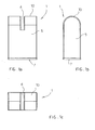
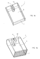
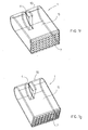
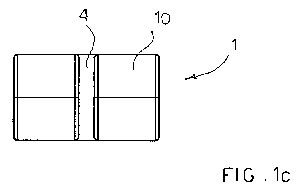
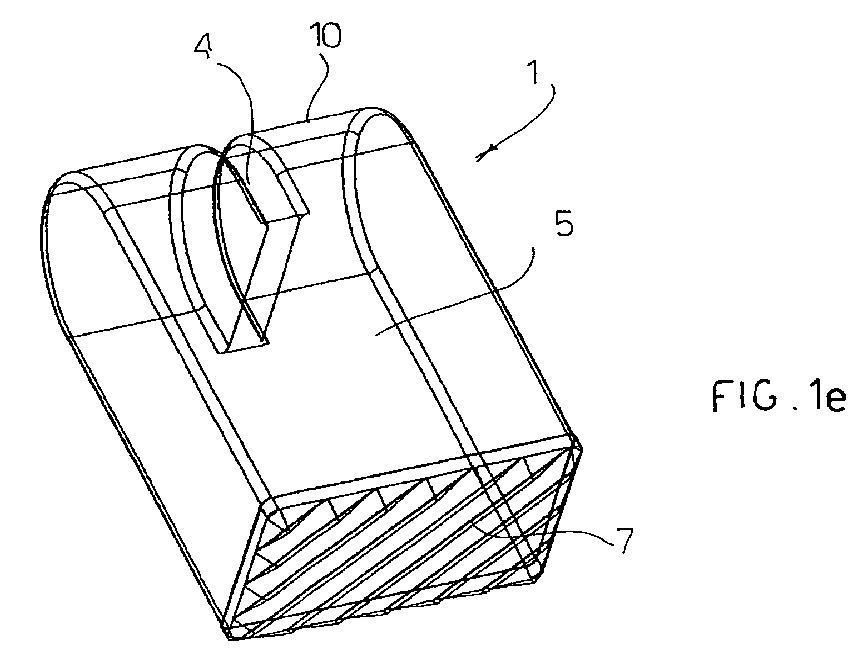
- Figure 1 shows diagrammatically a front view (Figure 1a), a side view ( Figure 1b), a top view (Figure 1c) and some bottom views, in perspective ( Figures 1d-1g), of a first block 1, realised according to the present invention, adapted to occupy a cavity 6 ( Figure 3) of a hollow tongue 3 of a spacer 2.
- the block 1 consists of a body 5, preferably made of plastic material, having a height equal to that of a cavity 6 and a shape matching that of said cavity; at least the surface 7 of the block 1 placed in contact with the inner pipe is preferably made of or coated with silicone rubber or another functionally equivalent synthetic plastic material.
- the surface 7 can be smooth (Figure 1d) or knurled; Figures 1e-1g show, by way of non-limiting example, some possible knurled surfaces 7.
- the whole block 1 can be made of silicone rubber or of another functionally equivalent synthetic plastic material.
- the block 1 can be made of a metal material (for example: steel) and coated, at least at the surface 7, with silicone rubber or with another functionally equivalent synthetic plastic material.
- the block 1 can be completely coated with silicone rubber or with another functionally equivalent synthetic plastic material.
- the hollow tongues 3 preferably have inside them walls 9 which divide them into a plurality of cavities 6: the body 5 of the block 1 has a shape matching that of said cavities 6.
- the body 5 of the block 1 can advantageously have, corresponding with the surface 10 thereof destined to come into contact with the bottom of the cavity 6, a seat 4 adapted to engage in a guide wall 8 ( Figure 3) present in the cavities 6 of a hollow tongue 3.
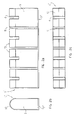
- Figure 2 shows diagrammatically a front view (Figure 2a), a side view ( Figure 2b), and a top view (Figure 2c) of a second block 1', realised according to the present invention, adapted to occupy all the cavities 6 ( Figure 4) of a hollow tongue 3 of a spacer 2.
- the block 1' differs from the block 1 in that it comprises a plurality of bodies 5, each of which has (or can have) a seat 4 (adapted to engage in a guide wall 8 present in a cavity 6 of the hollow tongue 3) connected to each other by a surface 7' (preferably made of or coated with silicone rubber) destined to come into contact with the inner pipe.
- the surface 7' can be smooth or knurled and can have, by way of non-limiting example, one of the knurled surfaces shown in Figures 1e-1g.
- two contiguous bodies 5 are preferably separated by a space I 1 adapted to accommodate one of the walls 9 which divide a hollow tongue 3 into a plurality of cavities 6.
- the seats 4 and/or the spaces 11 can be omitted if the hollow tongues 3 do not have the guide walls 8 and/or the dividing walls 9.
- Figure 3 shows diagrammatically a perspective view of the inner side of a spacer 2, in which two of the cavities 6 of the hollow tongues 3 are occupied by blocks 1.
- Figure 4 shows diagrammatically a perspective view of the inner side of a spacer 2, in which the hollow tongues 3 are occupied by a block 1'.
- a reinforcing block (1, 1') realised according to the invention presents numerous advantages among which is cited, by way of non limiting example, the fact that:
Landscapes
- Engineering & Computer Science (AREA)
- General Engineering & Computer Science (AREA)
- Mechanical Engineering (AREA)
- Prostheses (AREA)
- Manipulator (AREA)
Abstract




Description
- The present invention refers to a reinforcing block, preferably of plastic material, designed to be inserted into at least one of the hollow spacer tongues of a spacer for fluid conveying pipes.
- Reinforcing blocks are advantageously inserted only in the hollow spacer tongues belonging to the portion of the spacer on which the weight of the inner pipe bears, to stiffen said spacer tongues and to make them able to support the weight of said inner pipe.
- In the present description, the expression "hollow tongue" indicates a hollow body protruding from the body of the spacer, which can be a body with an elongated shape (Figures 3 and 4) or a series of hollow (preferably) cylindrical bodies.
- Fluid conveying pipes normally consist of an inner pipe (preferably) of steel or of a plastic material, inserted inside an outer pipe (preferably) of steel or of concrete: the inner pipe is kept centred with respect to the outer pipe by means of a plurality of spacers, which are applied to the outer surface of the inner pipe before it is inserted inside the outer pipe.
- Collar-type spacers having an inside diameter (substantially) coinciding with the outside diameter of the inner pipe and a plurality of radial spacer tongues are known to the art and available on the market.
- The spacers normally used consist of open collars, each of which is applied to the inner pipe in a pre-set position and is held in place by locking the facing ends of the collar to each other in a per se known manner.
- The spacer can consist of a plurality of elements coupled to each other to adapt the inside diameter of the collar to the outside diameter of the inner pipe.
- This type of spacer is described, for example, by the
European patent No. 1.262.700 in the Applicant's name. - Band-type spacers are also known to the art and available on the market, and comprise:
- a band-shaped body, sufficiently thin to bend so as to wrap around the inner pipe, from which protrudes (in a direction at right angles to the plane of said body) a plurality of spacer tongues;
- means, applied to at least one end of the band-shaped body, adapted to clamp the basic body around the inner pipe.
- Such band-type spacers are described, for example, by the
European patent No. 1.477.716 in the Applicant's name. - By realising a spacer having hollow spacer tongues, it is possible to reduce the amount of material used to make the spacer and, consequently, to reduce the production cost and the weight of the spacer.
- The above advantage is all the more appreciable the thinner the walls of the tongues are, but if the walls are (too) thin, the hollow tongues do not have (or may not have) the necessary mechanical strength to bear the weight of the inner pipe, keeping it centred with respect to the outer pipe.
- In order to overcome this drawback, it is necessary to give the walls of the tongues an adequate thickness (thus increasing the cost and the weight of the spacer) or - if the spacer is realised by joining together a plurality of elements - to make two types of elements, one with thick(er) walls for use in the area of the spacer on which the weight of the inner pipe bears, the other with thin(ner) walls for use in the remaining portions of the spacer.
- This solution brings obvious problems of procurement and of management of the two types of elements which form the spacer.
- Object of the present invention is to provide means adapted to strengthen, where and as much as necessary to bear the weight of the inner pipe on which it is mounted, a light, low-cost and compact spacer, which has a plurality of hollow spacer tongues with thin walls.
- This object is achieved by means of reinforcing blocks realised according to the present invention, which have the characterising elements illustrated in
claim 1; further advantageous characteristics of the invention form the subject matter of the dependent claims. - Further characteristics of the invention will be made clearer by the detailed description that follows, referring to a purely exemplifying and therefore non-limiting embodiment thereof, illustrated in the appended drawings, in which:
- Figure 1 shows diagrammatically a front view, a side view, a top view and some bottom views, in perspective, of a first block, realised according to the present invention, adapted to occupy a cavity of a hollow tongue of a spacer;
- Figure 2 shows diagrammatically a front view, a side view, and a top view of a second block, realised according to the present invention, adapted to occupy a hollow tongue of a spacer;
- Figure 3 shows diagrammatically a perspective view of a spacer, in which some cavities of the hollow tongues are occupied by blocks like those shown in Figure I;
- Figure 4 shows diagrammatically a perspective view of a spacer whose hollow tongues are occupied by a block like that shown in Figure 2.
- In the appended figures like elements will be designated by the same reference numerals.
- A block realised according to the invention to reinforce the hollow tongues of a spacer for fluid conveying pipes consists of at least one body (preferably of plastic material) having a height equal to the depth of the at least one cavity presented by a hollow tongue.
- If the hollow tongue consists of a series of hollow bodies, the body of the block has a height equal to the depth of the inner cavity of one of the hollow bodies.
- The body of a block realised according to the invention advantageously has a shape matching that of the at least one cavity presented by a hollow tongue, or that of the inner cavity of one of the hollow bodies, but without departing from the scope of the invention, the block can have a different shape from that of a cavity presented by a hollow tongue (or from that of the inner cavity of one of the hollow bodies) and/or comprise at least two parts side by side.
- Figure 1 shows diagrammatically a front view (Figure 1a), a side view (Figure 1b), a top view (Figure 1c) and some bottom views, in perspective (Figures 1d-1g), of a
first block 1, realised according to the present invention, adapted to occupy a cavity 6 (Figure 3) of a hollow tongue 3 of aspacer 2. - The
block 1 consists of abody 5, preferably made of plastic material, having a height equal to that of acavity 6 and a shape matching that of said cavity; at least thesurface 7 of theblock 1 placed in contact with the inner pipe is preferably made of or coated with silicone rubber or another functionally equivalent synthetic plastic material. - The
surface 7 can be smooth (Figure 1d) or knurled; Figures 1e-1g show, by way of non-limiting example, some possibleknurled surfaces 7. - Without departing from the scope of the invention, the
whole block 1 can be made of silicone rubber or of another functionally equivalent synthetic plastic material. - Again without departing from the scope of the invention, the
block 1 can be made of a metal material (for example: steel) and coated, at least at thesurface 7, with silicone rubber or with another functionally equivalent synthetic plastic material. - The
block 1 can be completely coated with silicone rubber or with another functionally equivalent synthetic plastic material. - As shown in Figures 3 and 4, the hollow tongues 3 preferably have inside them
walls 9 which divide them into a plurality of cavities 6: thebody 5 of theblock 1 has a shape matching that of saidcavities 6. - Furthermore, the
body 5 of theblock 1 can advantageously have, corresponding with thesurface 10 thereof destined to come into contact with the bottom of thecavity 6, aseat 4 adapted to engage in a guide wall 8 (Figure 3) present in thecavities 6 of a hollow tongue 3. - Figure 2 shows diagrammatically a front view (Figure 2a), a side view (Figure 2b), and a top view (Figure 2c) of a second block 1', realised according to the present invention, adapted to occupy all the cavities 6 (Figure 4) of a hollow tongue 3 of a
spacer 2. - The block 1' differs from the
block 1 in that it comprises a plurality ofbodies 5, each of which has (or can have) a seat 4 (adapted to engage in a guide wall 8 present in acavity 6 of the hollow tongue 3) connected to each other by a surface 7' (preferably made of or coated with silicone rubber) destined to come into contact with the inner pipe. - Like the
surface 7, the surface 7' can be smooth or knurled and can have, by way of non-limiting example, one of the knurled surfaces shown in Figures 1e-1g. - In the embodiment illustrated in Figure 2, two
contiguous bodies 5 are preferably separated by a space I 1 adapted to accommodate one of thewalls 9 which divide a hollow tongue 3 into a plurality ofcavities 6. - Without departing from the scope of the invention, the
seats 4 and/or thespaces 11 can be omitted if the hollow tongues 3 do not have the guide walls 8 and/or the dividingwalls 9. - For the sake of simplicity of the graphic representation, in Figure 2 only one of the
seats 4, of thebodies 5 and of thespaces 11 has been identified with the corresponding reference numeral. - Figure 3 shows diagrammatically a perspective view of the inner side of a
spacer 2, in which two of thecavities 6 of the hollow tongues 3 are occupied byblocks 1. - In Figure 3 the
bocks 1 having theseats 4, the hollow tongues 3, the cavities 6 (possibly) separated by thewalls 9 and the (possible) guide walls 8 for theseats 4 are visible; for the sake of simplicity of the graphic representation, in Figure 3 only one of theblocks 1, of the hollow tongues 3, of theseats 4, of thecavities 6, of the guide walls 8 and of the dividingwalls 9 has been identified with the corresponding reference numeral. - Four successive steps of the insertion of the
blocks 1 into thecavities 6 of the hollow tongues 3 of thespacer 2 are shown in Figure 3, looking at the figure from right to left (positions a-d). - In particular two
blocks 1, initially facing the cavities 6 (position a) are progressively inserted into the cavities 6 (positions b and c) until they are completely inserted therein (position d, bottom block 1). - Figure 4 shows diagrammatically a perspective view of the inner side of a
spacer 2, in which the hollow tongues 3 are occupied by a block 1'. - In Figure 4 the blocks 1' comprising a plurality of
bodies 2 having theseats 4 and divided by thespaces 11, the hollow tongues 3 and the cavities 6 (possibly) divided by thedivision walls 9 are visible; for the sake of simplicity of the graphic representation, in Figure 4 only one of the blocks 1', of thebodies 2, of the hollow tongues 3, of theseats 4, of thecavities 6, of thedividing walls 9 and of thespaces 11 has been identified with the corresponding reference numeral. - Four successive steps of the insertion of the blocks 1' into a
cavity 6 of a hollow tongue 3 of thespacer 2 are shown in Figure 4, looking at the figure from right to left (positions a-d). - In particular the block 1', initially facing the cavity 6 (position a) is progressively inserted therein (positions b and c) until it is completely inserted therein (position d).
- A reinforcing block (1, 1') realised according to the invention presents numerous advantages among which is cited, by way of non limiting example, the fact that:
- the
layer 7 of plastic material does not damage the inner pipe; - the weight of the inner pipe compresses the hollow tongues 3 and the blocks (1, 1'), thus making the
surface 7 of said blocks to adhere better to the inner pipe and increasing the frictional force between the spacer and the inner pipe; - by appropriately choosing the material used to realise the
body 5, it is possible to give the block (1, 1') the mechanical strength considered most advantageous on a case-by-case basis to meet specific needs. - Without departing from the scope of the invention, a person skilled in the art can make to the block previously described all the modifications and improvements suggested by normal experience and/or by the natural evolution of the art.
Claims (13)
- A reinforcing block (1, 1') for the hollow tongues (3) of a spacer (2) for fluid conveying pipes, the spacer (2) having at least one hollow tongue (3), characterised in that it comprises at least one body (5) having a height equal to the depth of at least one cavity (6) belonging to the at least one hollow tongue (3).
- A block (1,1') as in claim 1, characterised in that the body (5) has a shape matching that of at least one cavity (6) belonging to the at least one hollow tongue (3).
- A block (1, 1') as in claim 1, characterised in that the body (5) comprises at least two parts side by side with each other.
- A block (1,1') as in claim 1, characterised in that it is made of plastic material.
- A block (1,1') as in claim 4, characterised in that it is made of silicone rubber.
- A block (1,1') as in claim 1, characterised in that the surface (7, 7') thereof in contact with the inner pipe is made of plastic material.
- A block (1,1') as in claim 1, characterized in that the surface (7, 7') thereof in contact with the inner pipe is smooth.
- A block (1,1') as in claim 1, characterized in that the surface (7, 7') thereof in contact with the inner pipe is knurled.
- A block (1,1') as in claim 1, characterised in that the body (5) is made of metal material and is coated, at least on the surface (7, 7') thereof in contact with the inner tube, with a plastic material.
- A block (1,1') as in claim 1, characterized in that the body (5) of the block (1,1') has, corresponding with its surface (10) destined to come into contact with the bottom of the at least one cavity (6), at least one seat (4) able to engage in at least one guide wall (8) present in the at least one cavity (6) of the at least one hollow tongue (3).
- A block (1') as in at least one of the preceding claims, characterized in that it comprises a plurality of bodies (5), connected to each other by a surface (7') destined to come into contact with the inner pipe.
- A block (1') as in claim 11, characterized in that each of the bodies (5) has at least one seat (4) able to engage in at least one guide wall (8) present in one of the cavities (6) of the at least one hollow tongue (3).
- A block (1') as in claim 11, characterised in that two contiguous bodies (5) are separated by a space (11) able to accommodate one of the walls (9) which divide a hollow tongue (3) into a plurality of cavities (6).
Applications Claiming Priority (1)
| Application Number | Priority Date | Filing Date | Title |
|---|---|---|---|
| ITMI20061681 ITMI20061681A1 (en) | 2006-09-04 | 2006-09-04 | REINFORCEMENT BLOCK OF THE HONEY FLAPS OF A SPACER FOR TUBE TRANSPORT OF FLUIDS |
Publications (2)
| Publication Number | Publication Date |
|---|---|
| EP1895221A2 true EP1895221A2 (en) | 2008-03-05 |
| EP1895221A3 EP1895221A3 (en) | 2012-06-20 |
Family
ID=38521913
Family Applications (1)
| Application Number | Title | Priority Date | Filing Date |
|---|---|---|---|
| EP07014320A Withdrawn EP1895221A3 (en) | 2006-09-04 | 2007-07-20 | Reinforcing block for the hollow tongues of a spacer for fluid conveying pipes |
Country Status (2)
| Country | Link |
|---|---|
| EP (1) | EP1895221A3 (en) |
| IT (1) | ITMI20061681A1 (en) |
Family Cites Families (7)
| Publication number | Priority date | Publication date | Assignee | Title |
|---|---|---|---|---|
| DE7610105U1 (en) * | 1976-04-01 | 1976-07-29 | Dieter Spezial-Isolierungen Gmbh & Co, 7401 Nehren | SPACER FOR PIPES THROUGH PROTECTIVE TUBES |
| DE2906487C2 (en) * | 1979-02-20 | 1987-04-16 | Dieter Spezial-Isolierungen GmbH & Co., 7401 Nehren | Skid belt element for belting a product pipe that can be inserted into a protective pipe |
| DE8215746U1 (en) * | 1982-05-29 | 1984-08-16 | Rohmen, Peter, 5963 Wenden | ISOLATING DISTANCE PIPE FOR PIPES THROUGH PROTECTIVE PIPES |
| DE4134466A1 (en) * | 1991-10-18 | 1993-04-22 | Eberspaecher J | DOUBLE-WALLED AIR-INSULATED TUBE FOR EXHAUST SYSTEMS IN VEHICLES |
| DE20112795U1 (en) * | 2001-08-01 | 2001-10-11 | Göhner, Siegfried, 72116 Mössingen | Spacers for media pipes to be passed through jacket pipes |
| US6736166B2 (en) * | 2002-04-26 | 2004-05-18 | Advance Products And Systems, Inc. | Casing spacer |
| EP1598582B1 (en) * | 2004-05-19 | 2007-10-31 | Stampa Tecnica Articoli Materiali Plastici- S.T.A.M.P. S.P.A. | Adapter for spacer for pipes such as gas pipelines, oil pipelines and the like |
-
2006
- 2006-09-04 IT ITMI20061681 patent/ITMI20061681A1/en unknown
-
2007
- 2007-07-20 EP EP07014320A patent/EP1895221A3/en not_active Withdrawn
Also Published As
| Publication number | Publication date |
|---|---|
| EP1895221A3 (en) | 2012-06-20 |
| ITMI20061681A1 (en) | 2008-03-05 |
Similar Documents
| Publication | Publication Date | Title |
|---|---|---|
| JP2021525193A (en) | Chassis control arm for motorized vehicles | |
| US6513277B1 (en) | Pass-through fishing rod and method of manufacturing same | |
| EP2208596A2 (en) | Systems and methods of installing hook fastener elements in a mold assembly | |
| AU2010346932B2 (en) | Coil support member | |
| EP3595861B1 (en) | Method of making a fluid manifold | |
| WO2005106305A1 (en) | Apparatus and method for shaping hose | |
| EP0385730A1 (en) | Composite plastics tube | |
| CA2656459A1 (en) | Ribbed hose for milk extraction | |
| EP1895221A2 (en) | Reinforcing block for the hollow tongues of a spacer for fluid conveying pipes | |
| US8881572B2 (en) | Supporting core for producing hollow profiled elements | |
| US5624724A (en) | Self retainable shim | |
| CN109983270B (en) | Vibration isolation insert for pipe clamp | |
| CN106794613B (en) | Seismic isolation insert for pipe clamps and method of making such an insert | |
| EP0608068A1 (en) | Cage for reinforcing a concrete pile | |
| EP2350395B1 (en) | Formwork module and method of constructing a foundation | |
| AU2006215489A1 (en) | Tip for sampling pipette and pipette thus equipped | |
| CA2265350C (en) | Masonry hanger | |
| JP5769192B2 (en) | Raising frame for septic tank | |
| JP3901691B2 (en) | Tube fixing structure and tube fixing method | |
| EP1598582B1 (en) | Adapter for spacer for pipes such as gas pipelines, oil pipelines and the like | |
| EP1477716A1 (en) | Spacer for fluid conveying pipes | |
| JPS6014569Y2 (en) | Aids for bending flexible tubes | |
| JP3109944U (en) | Rebar spacer | |
| NL8700154A (en) | TUBE CONNECTION PARTICULARLY FOR DRAINAGE PIPES. | |
| KR200423652Y1 (en) | Release-plated steel wire used to reinforce masonry walls |
Legal Events
| Date | Code | Title | Description |
|---|---|---|---|
| PUAI | Public reference made under article 153(3) epc to a published international application that has entered the european phase |
Free format text: ORIGINAL CODE: 0009012 |
|
| AK | Designated contracting states |
Kind code of ref document: A2 Designated state(s): AT BE BG CH CY CZ DE DK EE ES FI FR GB GR HU IE IS IT LI LT LU LV MC MT NL PL PT RO SE SI SK TR |
|
| AX | Request for extension of the european patent |
Extension state: AL BA HR MK YU |
|
| PUAL | Search report despatched |
Free format text: ORIGINAL CODE: 0009013 |
|
| AK | Designated contracting states |
Kind code of ref document: A3 Designated state(s): AT BE BG CH CY CZ DE DK EE ES FI FR GB GR HU IE IS IT LI LT LU LV MC MT NL PL PT RO SE SI SK TR |
|
| AX | Request for extension of the european patent |
Extension state: AL BA HR MK RS |
|
| RIC1 | Information provided on ipc code assigned before grant |
Ipc: F16L 7/00 20060101AFI20120511BHEP |
|
| AKY | No designation fees paid | ||
| REG | Reference to a national code |
Ref country code: DE Ref legal event code: R108 |
|
| REG | Reference to a national code |
Ref country code: DE Ref legal event code: R108 Effective date: 20130227 |
|
| STAA | Information on the status of an ep patent application or granted ep patent |
Free format text: STATUS: THE APPLICATION IS DEEMED TO BE WITHDRAWN |
|
| 18D | Application deemed to be withdrawn |
Effective date: 20121221 |